

Page 1
RS-LiDAR-16 User Manual
1
Page 2

2
Revision History
Revision
Content
Date
Edited by
1.0
Initial release
2017-03-01
RD
3.0
Fill in the content according to RS-LiDAR-16 1.0
hardware.
2017-05-10
RD
3.1
Modify the relationship between laser channel and
vertical angle
2017-06-13
PD
3.2
Update the content according to RS-LiDAR-16 2.0
hardware
Add the timestamp calculation method for every point
2017-07-17
PD
3.3
Improve the range to 150m
Delete the description that MAC addressing is the
same as serial number
Add azimuth interpolation calculation method
Corrected the data structure of UCWP
Add the instruction for RSVIEW
Add the instruction for ROS driver
2017-08-10
PD
3.4
Add the frame description for ROS driver
Add the RS-LiDAR information in RSVIEW
2017-08-23
PD
3.5
Correct the description for horizontal resolution
Add the description for LiDAR mechanical origin
2017-09-16
PD
3.6
Update the RS-LiDAR information and data port
setting
Update the protocol description of DIFOP
2017-12-05
PD
3.7
Correct the depth dimension of the mount hole
Add Phase Lock
Add fault diagnosis
Add operation status
2018-02-05
PD
3.8
Add trouble shooting
2018-03-15
PD
4.0
Add LiDAR flag for MSOP
Update DIFOP protocol
Add top and bottom board flag description
Add GPS input status flag
Add laser mechanical position
Add bottom board firmware online update
Add fault diagnosis usage
Add LiDAR installation suggestion
2018-06-25
PD
RS-LiDAR-16 User Manual
Page 3

RS-LiDAR-16 User Manual
3
4.1
Add the sensor clean instruction
Add the RSVIEW compatible instruction
Add the LiDAR cable route instruction
2018-08-04
PD
4.2
Refine LiDAR power supply considerations
Add the instruction of space between the LiDAR and
mounting brackets
Modify the DIFOP data format
Add laser eye safety level instructions
Add aviation connector description and definition
Add Interface Box connection diagram
Update GPS synchronization protocol description
Add RS232 to TTL adapter wiring diagram and PIN
definition
Add return mode description
Add information to fault diagnosis
Modify the UCWP data format and add the FOV
setting description
Update Appendix C RSView content
Add the description of distance resolution 0.5cm
Add the description of intensity mode 3
2019-04-25
PD
V4.3
This version of the manual is applicable to radars of
V4.0 and later versions. For radars of previous
versions of V4.0, please refer to the manual of version
4.2.
Modify the definition and schematic diagram of the air
interface
Add the cleaning reminder in harsh environments
Adapted to the V4.0 version of the LiDAR, the number
of points per second is modified from 320000/s to
~300000/s
Adapted to the V4.0 version of the LiDAR, the
horizontal resolution of the point cloud is modified
from 0.09° -0.36° to 0.1° -0.4°
Change the working temperature to -30°C -60°C
Adapted to the V4.0 version of the LiDAR, at the
accurate point time calculation in Appendix A, the
transmission interval between the channels of the
device is changed from 3 μs to 2.8 μs, and the block
time is changed from 50 μs to 55.5 μs
Add description of replacing LiDAR configuration file
in Ubuntu system
2019-07-10
PD
Page 4

RS-LiDAR-16 User Manual
4
Add GPS interface PIN definition of the V4.0 version
LiDAR’s interface box
4.3.1
Update electrical interface diagram
Add "LiDAR" to the network wiring definition
4.3.2
Correct some description faults
Add LiDAR mechanical installation suggestion
Update download address of RSView
Add LiDAR dimension diagram
Add footnote for specification in chapter 3
2019-12-11
PD
4.3.3
Replace the dimension drawing in Appendix E
Modify some descriptions
2020-02-18
PD
Page 5

5
TABLE OF CONTENTS
RS-LiDAR-16 User Manual
1 Safety Notices
2 Introduction
3 Product Specifications
3.1 Product Format
3.2 Accuracy
4 Connections
4.1 Power
4.2 Electrical Configuration
4.3 Interface Box Description
4.4 Interface Box Connection
5 Communications Protocols
5.1 MSOP
........................................................................................................................................................
...........................................................................................................................................................
........................................................................................................................................
.........................................................................................................................................
....................................................................................................................................................
.........................................................................................................................................................
.........................................................................................................................................................
.........................................................................................................................................................
...........................................................................................................................
.......................................................................................................................
.......................................................................................................................
................................................................................................................................
9
10
11
11
12
13
13
13
14
16
17
18
5.1.1 Header
5.1.2 Data Field
5.1.3 Tail
5.1.4 Demonstration Data
5.2 DIFOP
5.3 UCWP
6 GPS Synchronization
6.1 GPS Synchronization Theory
6.2 GPS Usage
7 Key Features
7.1 Return Mode
........................................................................................................................................................
........................................................................................................................................................
........................................................................................................................................................
7.1.1 Return Mode Principle
............................................................................................................................................
.......................................................................................................................................
...................................................................................................................................................
..........................................................................................................................................
...............................................................................................................................................
.............................................................................................................................................
.....................................................................................................................
.................................................................................................................
.................................................................................................................
19
20
22
22
24
25
28
28
28
30
30
30
7.1.2 The Strongest Return
...................................................................................................................
30
Page 6

RS-LiDAR-16 User Manual
6
7.1.3 Strongest, Last and Dual Returns
7.1.4 Return Mode Flag
7.2 Phase Lock
8 Point Cloud
...........................................................................................................................................................
...............................................................................................................................................
8.1 Coordinate Mapping
8.2 Point Cloud Presentation
.........................................................................................................................
................................................................................................................................
........................................................................................................................
9 Laser Channels and Vertical Angles
10 Calibrated Reflectivity
11 Troubleshooting
Appendix A ▪ Point Time Calculate
Appendix B ▪ Information Registers
B.1 Motor(MOT_SPD)
.......................................................................................................................................
.................................................................................................................................................
......................................................................................................................
.....................................................................................................................
....................................................................................................................................
.............................................................................................
................................................................................................................
30
30
31
32
32
32
34
36
38
40
41
41
B.2 Ethernet(ETH)
B.3 FOV Setting (FOV SET)
B.4 Motor Phase Offset (MOT_PHASE)
B.5 Top Board Firmware (TOP_FRM)
B.6 Bottom Board Firmware (BOT_FRM)
..........................................................................................................................................
.........................................................................................................................
.....................................................................................................
.........................................................................................................
..................................................................................................
B.7 Corrected Vertical Angle (COR_VERT_ANG)
B.8 Serial Number(SN)
B.9 Software Version(SOFTWARE_VER)
B.10 UTC Time(UTC_TIME)
B.11 STATUS
...................................................................................................................................................
B.12 Fault Diagnosis
B.13 ASCII code in GPRMC Packet
..................................................................................................................................
..................................................................................................
.........................................................................................................................
......................................................................................................................................
............................................................................................................
....................................................................................
41
42
42
42
43
43
44
44
44
46
47
48
Appendix C ▪ RSView
C.1 Features
C.2 Install RSView
C.3 Set up Network
............................................................................................................................................
....................................................................................................................................................
..........................................................................................................................................
........................................................................................................................................
49
49
49
49
Page 7

RS-LiDAR-16 User Manual
7
C.4 Visualize Streaming Sensor Data
.........................................................................................................
C.5 Capture Streaming Sensor Data to PCAP File
C.6 Replay Captured Sensor Data from PCAP File
C.7 RS-LiDAR-16 Factory Firmware Parameters Setting
C.8 RSView Data Port
C.9 Firmware Online Update
C.10 Fault Diagnosis
Appendix D ▪ RS-LiDAR-16 ROS Package
D.1 Prerequisite
D.2 Install RS-LiDAR-16 ROS Package
D.3 Configure PC IP address
D.4 View the real time data
...................................................................................................................................
........................................................................................................................
......................................................................................................................................
........................................................................................................
..............................................................................................................................................
.....................................................................................................
.......................................................................................................................
...........................................................................................................................
..................................................................................
.................................................................................
.......................................................................
50
51
52
54
56
56
57
59
59
59
59
59
D.5 View the recorded pcap file offline
Appendix E ▪ Dimensions
......................................................................................................................................
Appendix F ▪ LiDAR Mechanical Installation Suggestion
.......................................................................................................
................................................................................
Appendix G ▪ How to Distinguish the Port Number of MSOP and DIFOP Packets
Appendix H ▪ Sensor clean
H.1 Attention
....................................................................................................................................................
H.2 Require Materials
H.3 Clean Method
...................................................................................................................................
....................................................................................................................................
...........................................................................................................................................
....................................
60
62
63
64
65
65
65
65
Page 8

8
Terminologies
MSOP
Main Data Stream Output Protocol
DIFOP
Device Info Output Protocol
UCWP
User Configuration Write Protocol
Azimuth
Horizontal angle of each laser firing
Timestamp
The marker that records the system time
Header
The starting part of the protocol packet
Tail
The ending part of the protocol packet
RS-LiDAR-16 User Manual
Page 9

RS-LiDAR-16 User Manual
9
Congratulations on your purchase of a RS-LiDAR-16 Real-Time 3D LiDAR Sensor. Please read
carefully before operating the product. Wish you a pleasurable product experience with RS-LiDAR-16.
1 Safety Notices
To reduce the risk of electric shock and to avoid violating the warranty, do not open sensor body.
Laser safety - The laser safety complies with IEC 60825-1:2014.
Read Instructions - All safety and operating instructions should be read before operating the
product.
Follow Instructions - All operating and use instructions should be followed.
Retain Instructions - The safety and operating instructions should be retained for future reference.
Heed Warnings - All warnings on the product and in the operating instructions should be adhered
to.
Servicing - The user should not attempt to service the product beyond what is described in the
operating instructions. All other servicing should be referred to RoboSense.
Page 10
RS-LiDAR-16 User Manual
10
2 Introduction
RS-LiDAR-16, launched by RoboSense, is the first of its kind in China, world leading 16-beam miniature
LiDAR product. Its main applications are in autonomous driving, robot-environment perception and UAV
mapping.
RS-LiDAR-16, as a solid-state hybrid LiDAR, integrates 16 laser/detector pairs mounted in a compact
housing.
Unique features include:
Measurement range of up to 150 meters
Within 2 centimeters measurement accuracy
Data rate of up to 300,000 points/second
Horizontal Field of View (FOV) of 360°
Vertical Field of View (FOV) of 30° (-15°~+15°)
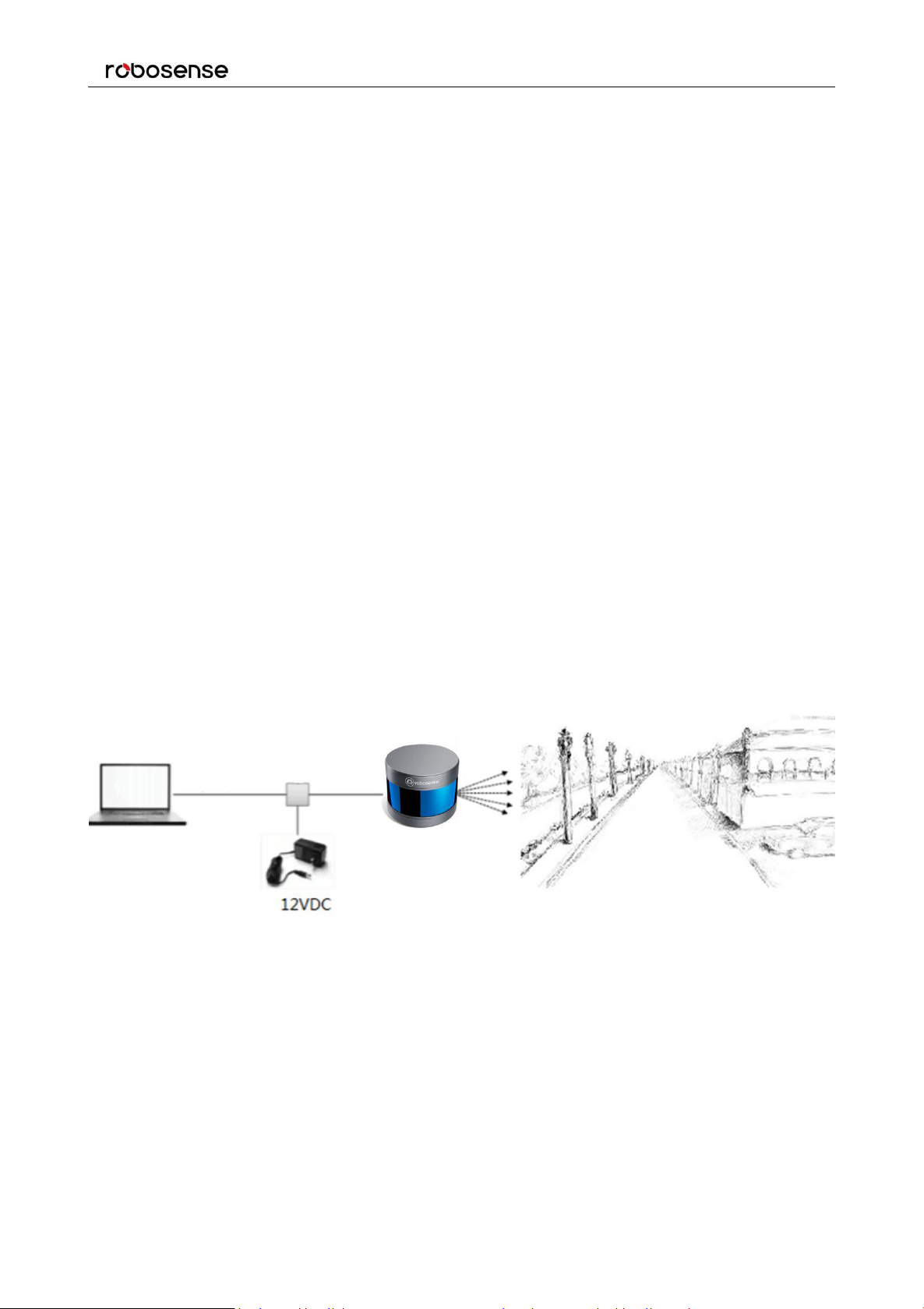
The compact housing of RS-LiDAR-16 mounted with 16 laser/detector pairs rapidly spins and sends out
high-frequency laser beams to continuously scan the surrounding environment. Advanced digital signal
processing and ranging algorithms calculate point cloud data and reflectivity of objects to enable the
machine to “see” the world and to provide reliable data for localization, navigation and obstacle
avoidance.
Figure 1: RS-LiDAR Imaging System.
Operation of device include:
Establish communication with RS-LiDAR-16;
Parse the data packets for azimuth, measured distance, and reported calibrated reflectivity;
Calculate X, Y, Z coordinates from reported azimuth, measured distance, and vertical angle;
Store the data as needed;
Read current device configuration data;
Set Ethernet, time and rotational speed as needed.
Page 11

RS-LiDAR-16 User Manual
11
Sensor
Time of Flight Distance Measurement
16 Channels
Measurement Range: 40cm to 150m (on 20% reflectivity target)
2
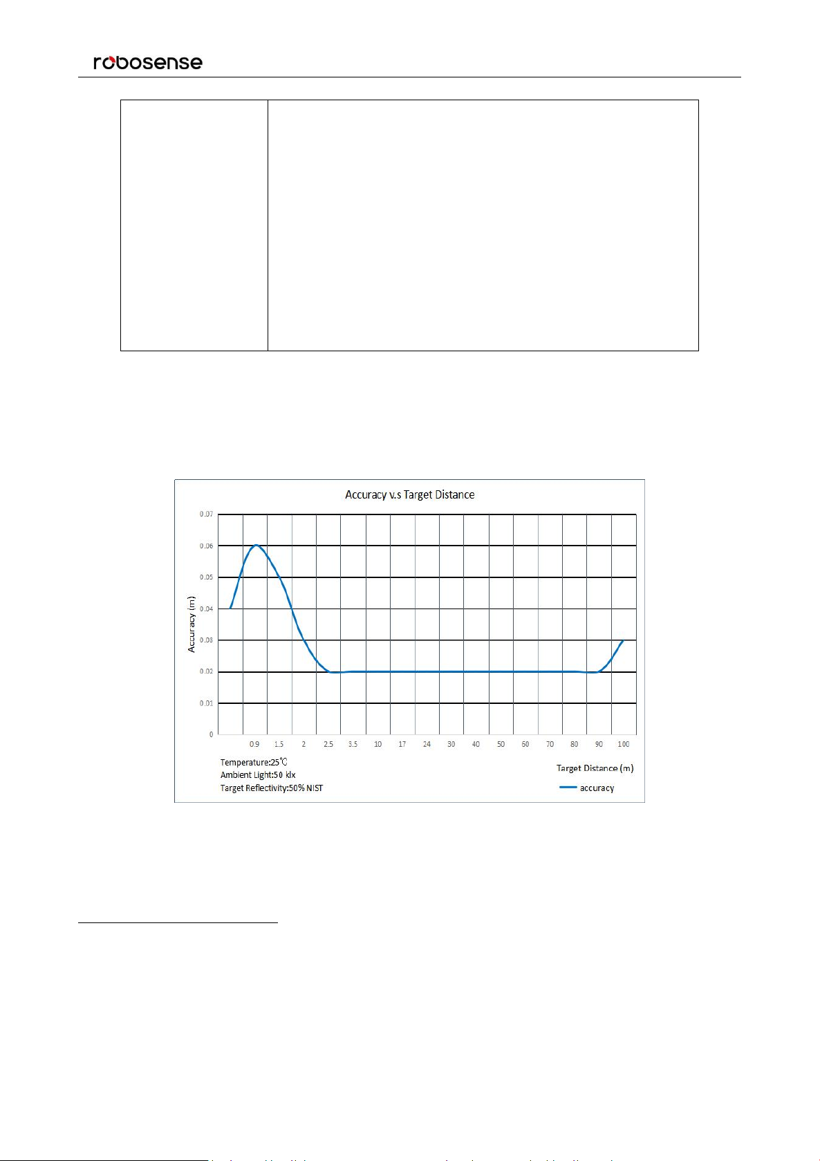
Accuracy: ±2cm (typical, refer to Figure 2)
3
Field of View (Vertical): ±15.0° (30° in total)
Angular Resolution (Vertical): 2°
Field of View (Horizontal): 360°
Angular Resolution (Horizontal/Azimuth): 0.1°(5Hz) to 0.4°(20Hz)
Rotation Rate: 300/600/1200 rpm(5/10/20 Hz)
Laser
Class 1
Wavelength: 905nm
Full Beam Divergence Horizontal: 7.4 mrad, Vertical: 1.4 mrad
Output
Data Rate: ~300,000 points/second
100Mbps Ethernet
UDP packet, include:
Distance
Rotation Angle/Azimuth
Calibrated Reflectivity
Synchronized Timestamp (Resolution: 1us)
3 Product Specifications
3.1 Product Format
1
Table 1: Product Parameters.
1
The following data is only for mass-produced products. Any samples, testing machines and other non-mass-produced versions
may not be referred to this specification. If you have any questions, please contact RoboSense sales.
2
The measurement target of rang is a 20% NIST Diffuse Reflectance Calibration Targets, the test performance is depending on
circumstance factors, not only temperature, range and reflectivity but also including other uncontrollable factors.
Page 12
12
3.2 Accuracy
Mechanical/
Electrical/
Operational
Power Consumption:12 W (typical)
4
Operating Voltage: 9-32 VDC (with Interface Box and Regulated
Power Supply)
Weight: 0.87 Kg (without cable)
Dimensions: 109 mm Diameter X 80.7 mm Height
Environmental Protection: IP67
Operation Temperature: -30 ℃ to +60 ℃
5
Storage Temperature: -40 ℃ to +85 ℃
RS-LiDAR-16 User Manual
Figure 2: The Relation between accuracy and distance of target object.
3
The measurement target of accuracy is a 50% NIST Diffuse Reflectance Calibration Targets, the test performance is depending on
circumstance factors, not only temperature, range and reflectivity but also including other uncontrollable factors.
4
The test performance of power consumption is depending on circumstance factors, not only temperature, range and reflectivity but
also including other uncontrollable factors.
5
Device operating temperature is depending on circumstance, including but not limited to ambient lighting, air flow and pressure
etc.
Page 13
RS-LiDAR-16 User Manual
13
4 Connections
4.1 Power
When equipped with an interface box, the device requires a voltage range of 9-32 VDC, and 12 VDC is
recommended.
If the interface box is not used for the LiDAR, a regulated 12 VDC must be used, while the V4.0 and
later versions of the LiDAR integrate the wide-voltage function internally, so you can continue to use
9-32 VDC.
The power consumption of the device is about 12 W (typical).
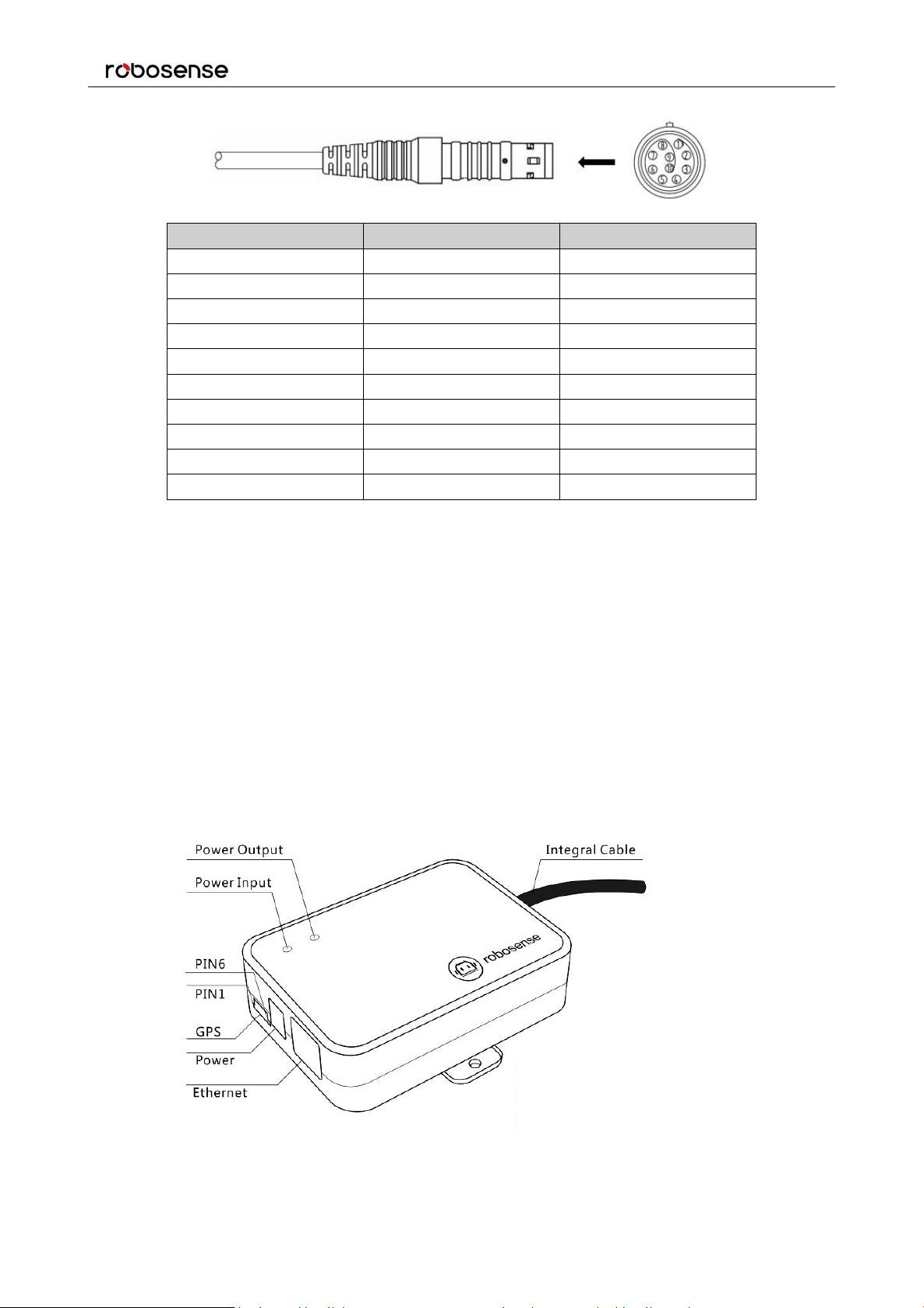
4.2 Electrical Configuration
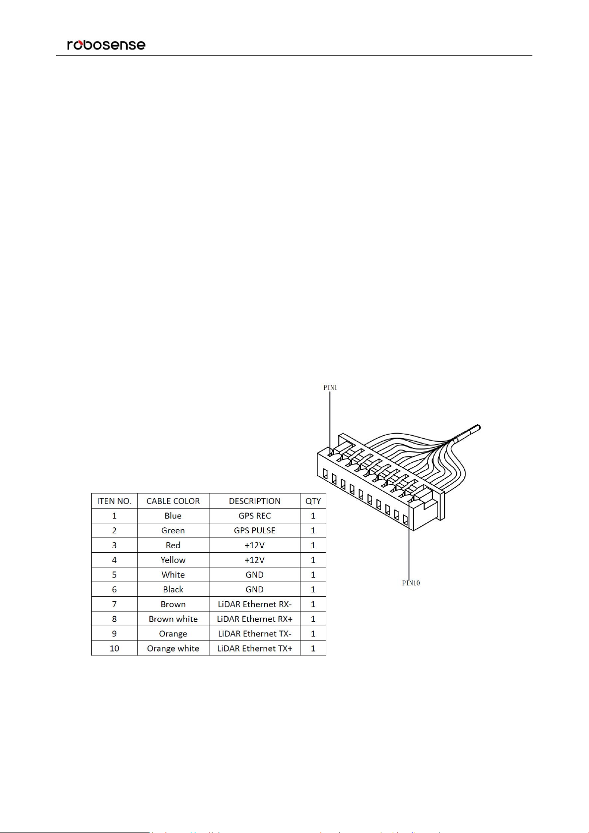
RS-LiDAR-16 comes with an integral cable(power/data) that is permanently attached to the sensor and
terminates at a standard SH1.25 wiring terminal. Figure 3 illustrates the serial PINs and their properties.
To operate RS-LiDAR-16, the user should insert the SH1.25 wiring terminal to the corresponding port on
the Interface BOX.
Figure 3: Wiring Terminal and Serialized PIN.
The RS-LiDAR-16 has a type that uses the aviation connector. The cable length between the LiDAR and
the aviation connector is 1 meter. The specific PINs of the aviation connector are defined as follows:
Page 14
RS-LiDAR-16 User Manual
14
PIN
Wire Color
Function
1
Red
+12V
2
Yellow
+12V
3
White
GROUND
4
Black
GROUND
5
Green
GPS PULSE
6
Blue
GPS REC
7
Brown
LiDAR Ethernet RX-
8
Brown white
LiDAR Ethernet RX+
9
Orange
LiDAR Ethernet TX-
10
Orange white
LiDAR Ethernet TX+
Figure 4: Aviation Plug PIN Number.
4.3 Interface Box Description
The Interface BOX is connected to the RS-LiDAR-16 by default.
The Interface BOX provides indicator LEDs for power, interfaces for power, 100Mbps Ethernet, and
GPS inputs. The DC 5.5-2.1 connector for power input, RJ45 Ethernet connector for RS-LiDAR-16 data
output and SH1.0-6P female connector for GPS input.
Note: The default cable of the interface box is 3 meters long, if you have other length requirements please
contact the RoboSense technical support. Because of the different LiDAR versions, there are two definitions
and different levels of the GPS port on the interface box.
The corresponding positions of the interface are as follows (As shown in Figure 5):
Page 15

RS-LiDAR-16 User Manual
15
PIN No.
V4.0 and later versions
Other versions
1
GPS PULSE
GPS REC
2
+5V
GPS PULSE
3
GND
GND
4
GPS REC
NC
5
GND
NC
6NC+5V
Figure 5: Interface definition on Interface Box.
Note: When RS-LiDAR-16 connects its grounding system with an external system, the external power
supply system should share the same grounding system with that of the GPS.
On the Interface BOX, the red light indicator means standard power input, and the green one means
standard power output. The Interface BOX access protection status when the red light indicator lights up
and green light indicator blacks out. If the red and green light indicators blink at the same time, please
check for errors of the power supply. If the power supply is checked without error, the high chance is that
the Interface BOX is damaged. Please return damaged Interface BOX to RoboSense for service.
GPS interface definition: GPS REC means GPS UART input, GPS PULSE means GPS PPS input.
Ethernet interface complies with EIA/TIA568 Standard.
Power interface adopts standard DC 5.5-2.1 connector.
Page 16
16
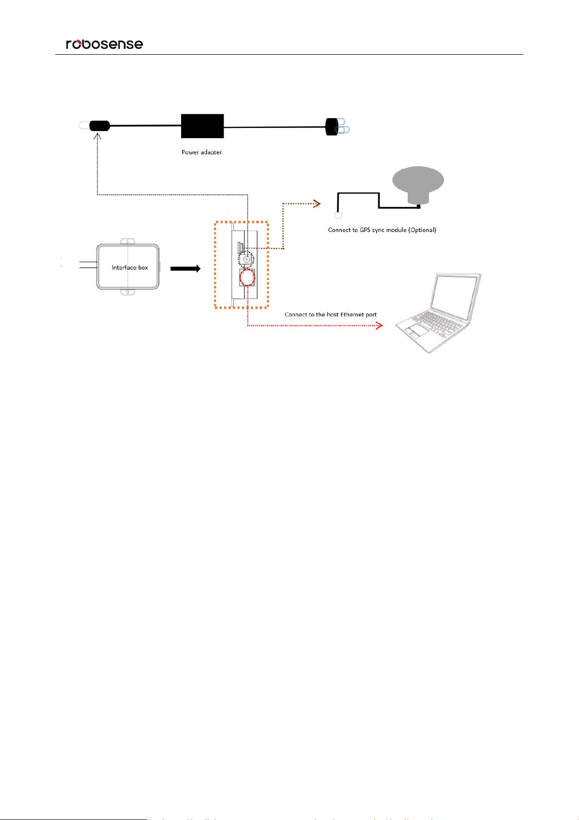
4.4 Interface Box Connection
RS-LiDAR-16 User Manual
Figure 6: Interface Box connection diagram.
Page 17

RS-LiDAR-16 User Manual
17
IP Address
MSOP Port No.
DIFOP Port No.
RS-LiDAR-16
192.168.1.200
6699
7788
Computer
192.168.1.102
Protocol
Abbreviation
Function
Type
Size
Interval
Main Data Stream Output Protocol
MSOP
Scan Data Output
UDP
1248byte
~1.33 ms
Device Information Output Protocol
DIFOP
Device Information Output
UDP
1248byte
~100 ms
User Configuration Write Protocol
UCWP
Sensor Parameters Setting
UDP
1248byte
INF
5 Communications Protocols
RS-LiDAR-16 adopts UDP protocol and communicates with computer through 100Mbps Ethernet.
There two different kinds of UDP output packets: MSOP packets and DIFOP packets. The UDP protocol
packet in this manual is of 1290 byte long, and consists of a 1248-bytes- payload and a 42-byte header.
The IP address and port number of RS-LiDAR-16 is set in the factory as shown in the Table 2, but can
be changed by the user as needed.
Table 2: The IP Address and Port Number Set at the Factory.
The default MAC Address of each RS-LiDAR-16 is set in the factory. The MAC Address can be changed
as needed.
To establish communication between a sensor and a computer, the IP address of the computer should
be set at the same network segment of that of the sensor. By default: 192.168.1.X (X can be taken by a
value from 1~254), subnet mask: 255.255.255.0. In case of uncertainty about the internet setting of the
sensor, please connect the sensor to the computer, and parse packet to get the IP and port through
Wireshark.
RS-LiDAR-16 adopts 3 kinds of communications protocols to establish communication with the
computer:
MSOP (Main Data Stream Output Protocol). Distance, azimuth and reflectivity data
collected by the sensor are packed and output to computer.
DIFOP (Device Information Output Protocol). Monitor the current configuration information
of the sensor.
UCWP (User Configuration Write Protocol). User can modify some parameters of the
sensor as needed.
Table 3: Protocols Adopted by RS-LiDAR-16.
Note:The following section describes and defines the valid payload (1248 byte) of the UDP protocol packet.
Page 18
RS-LiDAR-16 User Manual
18
channel data 16
channel data 16
channel data 16
channel data 32
channel data ...
channel data 17
channel data 17
channel data ...
channel data 32
channel data 17
channel data ...
channel data 32
42 bytes
data packet
12 * 100 bytes = 1200 bytes
MSOP Packet (1248 bytes)
6 bytes
42 bytes
(21st~30
th
byte is
time
stamp)
Header
Tail
4 bytes
resv. + 2
bytes
(0x00,
0xFF)
channel data 1
channel data 2
0xffee
Data block 1
Azimuth 1
channel data ...
channel data 16
channel data 1
channel data 2
0xffee
Data block 2
Azimuth 2
channel data ...
channel data 1
channel data 2
0xffee
Data block n
Azimuth n
channel data ...
channel data 1
channel data 2
0xffee
Data block 12
Azimuth 12
channel data ...
channel data 17
channel data ...
channel data 32
5.1 MSOP
I/O type: device output data, computer parse data.
Default port number is 6699.
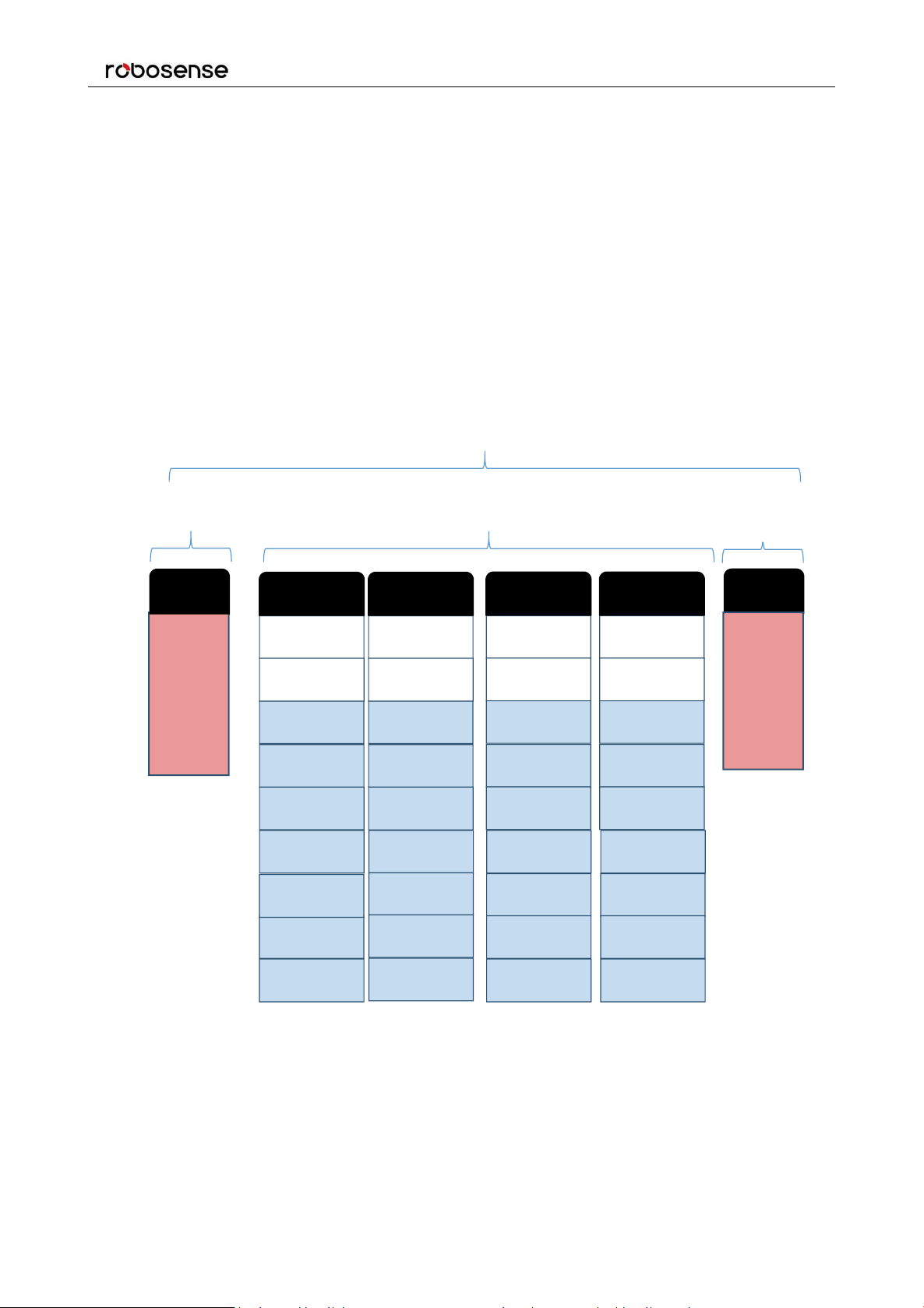
MSOP outputs data information of the 3D environment in packets. Each MSOP packet is 1248 bytes
long and consists of reported distance, calibrated reflectivity values, azimuth values and a time stamp.
Each RS-LiDAR-16 MSOP packet payload is 1248 byte long and consists of a 42-byte header and a
1200-byte data field containing twelve blocks of 100-byte data records and a 6-byte tail.
The basic data structure of a MSOP packet for single return is as shown in Figure 7.
Figure 7: Single Return MSOP Packet.
Page 19
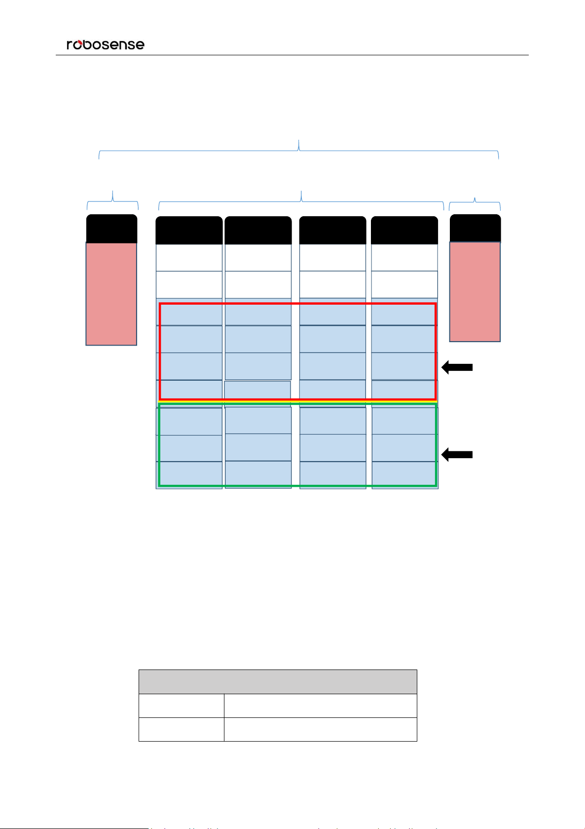
19
The basic data structure of a MSOP packet for dual return is as shown in Figure 8.
LiDAR Model (1 byte)
0x01
RS-LiDAR-16
0x02
RS-LiDAR-32
channel data 16
channel data 16
channel data 16
Second
Return
First
Return
channel data 32
channel data ...
channel data 17
channel data 17
channel data ...
channel data 32
channel data 17
channel data ...
channel data 32
42 bytes
data packet
12 * 100 bytes = 1200 bytes
MSOP Packet (1248 bytes)
6 bytes
42 bytes
(21st~30
th
byte is
time
stamp)
Header
Tail
4 bytes
resv. + 2
bytes
(0x00,
0xFF)
channel data 1
channel data 2
0xffee
Data block 1
Azimuth 1
channel data ...
channel data 16
channel data 1
channel data 2
0xffee
Data block 2
Azimuth 2
channel data ...
channel data 1
channel data 2
0xffee
Data block n
Azimuth n
channel data ...
channel data 1
channel data 2
0xffee
Data block 12
Azimuth 12
channel data ...
channel data 17
channel data ...
channel data 32
RS-LiDAR-16 User Manual
5.1.1 Header
The 42-byte header marks the beginning of data blocks. In the 42-byte data header, the first 8 bytes are
for header identification, the 21st. to 30th. byte records time stamp, the 31st byte represents the LiDAR
model, and the rest bytes are reserved for future updates.
The first 8 bytes of the header is defined as 0x55,0xAA,0x05,0x0A,0x5A,0xA5,0x50,0xA0.
Time stamp with a resolution of 1 μs records the system time. Please refer to the definition of time in
Appendix B.10 and Table 8 in part 3 of this section. The 31st byte LiDAR model is described as below:
Figure 8: Dual Return MSOP Packet Definition Diagram.
Table 4: LiDAR Model Flag.
Page 20

RS-LiDAR-16 User Manual
20
5.1.2 Data Field
Data field comprises data blocks that contain valid measurement data. Each data filed contains 12
blocks. Each block is 100-byte long and is a complete measurement data set. Each data block begins
with a 2-byte start identifier “0xffee”, then a two-byte azimuth value (rotational angle). Each azimuth
value records 32 sets of channel data reported by the 16 laser channels for two sequence. (Please see
chapter 9 for the relationship between channel sequence and vertical angel.)
5.1.2.1 Azimuth Value
The reported azimuth is associated with the first laser firing in each sequence of 16 laser firings. The
Azimuth Value is recorded by the encoder. The zero position on the encoder indicates the zero degree
of azimuth value on RS-LiDAR-16. In one data block, there are 32 sets of laser data indicating two
sequence of the 16 laser firings, however only every-other encoder angle is reported for alternate firing
sequences. So under single return mode user can choose to interpolate that unreported encoder stamp
(Refer to 5.1.2.2). The resolution of Azimuth is 0.01°.
For example, in Figure 10, the azimuth value is calculated through the following steps:
Get azimuth values: 0x00
Combine to a 16 bit, unsigned integer: 0x0044
Convert to decimal: 68
Divided by 100
Result: 0.68°
Hence the firing angle is 0.68°
Note: the position of 0° on sensor is the Y axis positive direction in Figure 14.
,
0x44
5.1.2.2 Azimuth Value Interpolation
Because the RS-LIDAR-16 reports the azimuth value for every-other firing sequence, it’s helpful to
interpolate the un-reported azimuth when the LiDAR works under single return. There are several ways
to interpolate the un-reported azimuth, but the one given below is simple and straight forward.
Consider a single data packet. The time between the first firing of the first sequence of sixteen firings
(Data Block 1) and the first firing of the third sequence of sixteen laser firings (Data Block 2) is
~100.0 µs. If you assume the rotation speed over that short interval is constant, you can assume the
azimuth of the (N+1) set of sixteen laser firings is halfway between the azimuth reported with the Nth set
of 16 laser firings and the azimuth reported with the (N+2) set of laser firings.
Below is pseudo-code that performs the interpolation. The code checks to see if the azimuth rolled over
from 359.99° to 0° between firing sequence N and N+2.
Page 21

21
In the example below, N=1.
Channel Data N (3 bytes)
2 bytes Distance
1 byte Reflectivity
Distance1 [15:8]
Distance2 [7:0]
Reflectivity
// First, adjust for a rollover from 359.99° to 0°
If (Azimuth[3] < Azimuth[1])
Then Azimuth[3]:= Azimuth[3]+360;
Endif;
// Perform the interpolation
Azimuth[2]:=Azimuth[1]+((Azimuth[3]-Azimuth[1])/2);
// Correct for any rollover over from 359.99° to 0°
If (Azimuth[2]>360)
Then Azimuth[2]:= Azimuth[2]-360;
Endif
RS-LiDAR-16 User Manual
5.1.2.3 Channel Data
Channel data contains 3 bytes, with the upper 2 bytes store distance information, and the lower 1 byte
contains reflectivity data. The structure of channel data is as shown in Table 5.
Table 5: Channel Data.
The 2-byte distance data is set in centimeter. The resolution is different between 1 cm and 0.5 cm due to
the different LiDAR firmware.
Reflectivity data records relative reflectivity (more definition on reflectivity, please refer to description on
calibrated reflectivity in Section 9 of this manual). Reflectivity data reveals the reflectivity performance of
the system in real measurement environments, it can be used in distinguishing different materials.
The following shows how to parse channel data.
In the case of Figure 10/11, the distance information is calculated by:
Get distance values: 0x06 ,0x42
Combine distance bytes to a 2-byte, unsigned integer: 0x0642
Convert to decimal: 1602
According to the distance resolution difference, it can be calculated:
1cm resolution result: 16.02 meters; 0.5cm resolution result: 8.01 meters;
Hence the distance measured is 16.02m.
Page 22

RS-LiDAR-16 User Manual
22
5.1.3 Tail
The tail is 6 bytes long, with 4 bytes unused and reserved for information, and the other 2 bytes as: 0x00,
0xFF.
5.1.4 Demonstration Data
Figure 9: MSOP Packet Display.
Page 23

RS-LiDAR-16 User Manual
23
Figure 10: 1 cm Resolution Data Block Display.
Figure 11: 0.5 cm Resolution Data Block Display.
Page 24

RS-LiDAR-16 User Manual
24
No.
Information
Offset
Length(byte)
Header
0
DIFOP header
0
8
Data
1
Motor rotation speed (MOT_SPD)
8
2
2
Ethernet (ETH)
10
22
3
FOV setting
32
4
4
Corrected static base (COR_STATIC_BASE)
36
2
5
Motor phase lock (MOT_PHASE)
38
2
6
Top board firmware version (TOP_FRM)
40
5
7
Bottom board firmware version (BOT_FRM)
45
5
8
Corrected intensity curves coefficient
50
240
9
Intensity scale
290
1
10
Intensity Mode
291
1
11
Serial number (SN)
292
6
12
Zero angle offset
298
2
13
Return mode
300
1
14
Upper computer compatibility
301
2
15
UTC time (UTC_TIME)
303
10
5.2 DIFOP
I/O type:device output, computer read.
Default port number is 7788.
DIFOP is a protocol that reports and outputs only device information including the device serial number,
firmware version, driver compatibility, internet setting, calibration data, electrical machine setting and
operation status, fault detection information to users. It is a viewer for users to get comprehensive
details about the device.
Each DIFOP packet is 1248 byte long, and comprises an 8-byte Header, a 1238-byte data field, and a
2-byte Tail.
The structure of DIFOP is as shown in Table 6.
Table 6: Data Format of DIFOP Packet.
Page 25

RS-LiDAR-16 User Manual
25
16
Operation status (STATUS)
313
18
17
Reserved
331
11
18
Fault diagnosis (FALT_DIGS)
342
40
19
GPRMC
382
86
20
Corrected static (COR_STATIC)
468
697
21
Corrected vertical angle (COR_VERT_ANG)
1165
48
22
Reserved
1213
33
Tail
23
Tail
1246
2
No.
Info
Offset
Length(byte)
Header0UCWP header
0
8
Data
1
Motor rotation speed
8
2
2
Ethernet
10
22
3
FOV setting
32
4
4
Time
36
10
5
Motor phase lock
46
2
Note: The Header (the DIFOP identifier) in the table above is 0xA5, 0xFF, 0x00, 0x5A, 0x11, 0x11, 0x55, 0x55, among
which the first 4 byte 0xA5,0xFF,0x00,0x5A is the sequence to identify the packet.
The tail is 0x0F,0xF0.
For definition of information registers as well as their usage, please check more details in Appendix B of
this manual.
5.3 UCWP
I/O type: computer writes into the device.
Function: user can reconfigure Ethernet connection, time and some parameters of the device.
Each UCWP Packet is 1248 byte long, and is comprised of an 8-byte Header and a 40-byte data field.
The UCWP packet structure is as shown below:
Table 7: Data Format of UCWP Packet.
Note: The Header (UCWP identifier) in the table above is 0xAA, 0x00, 0xFF, 0x11, 0x22, 0x22, 0xAA, 0xAA, among
Page 26

RS-LiDAR-16 User Manual
26
Information
Content
Setting
Length(byte)
Header
0xAA,0x00,0xFF,0x11,
0x22,0x22,0xAA,0xAA
8
Rotate Speed
1200rpm
0x04, 0xB0
2
LiDAR IP
(LIDAR_IP)
192.168.1.105
0xC0, 0xA8
0x01, 0x69
4
Destination PC IP
(DEST_PC_IP)
192.168.1.225
0xC0, 0xA8
0x01, 0xE1
4
Device MAC
Address(MAC_ADD
R)
001C23174ACC
0x00,0x1C,0x23,
0x17,0x4A,0xCC
6
MSOP Port(port1)
6688
0x1A20
2
MSOP Port(port2)
6688
0x1A20
2
which, the first 4 bytes 0xAA, 0x00, 0xFF, 0x11 forms the sequence to identify the packet.
Statement: RS-LiDAR-16 doesn’t RTC system to support operation while power is off. In the case of no
GPS or GPS signal, it is imperative to write time into the device through a computer, or it will use a
default system time for clock.
Refer to Appendix B of this manual for details on Ethernet, Time, Motor Rotation Speed and Motor
Phase Lock. Below is an example to configure the RS-LIDAR-16:
LiDAR IP: 192.168.1.105,
Destination PC IP: 192.168.1.225,
MAC_ADDR: 001C23174ACC
MSOP port: 6688
DIFOP port: 8899
FOV starting angle: 0°
FOV end angle: 120°
Time: 09:45:30:100:200, March 10, 2017
Rotation speed: 600rpm
Motor phase lock: 90 degree
User can reset the above information by following the example in Table 8.
Table 8: Setting of UCWP Packet.
Page 27

RS-LiDAR-16 User Manual
27
DIFOP Port(port3)
8899
0x22C3
2
DIFOP Port(port4)
8899
0x22C3
2
FOV starting angle
0
0x0000
2
FOV end angle
12000
0x2EE0
2
UTC_TIME
Year:2017
Month:3
Day:10
Hour:9
Minute:45
Second:30
Millisecond: 100
Microsecond: 200
0x11
0x03
0x0A
0x09
0x2D
0x1E
0x00,0x64
0x00,0xC8
10
Motor Phase Lock
90
0x005A
2
While setting the device and computer according to this protocol, it is imperative to set all the
information listed in the table above. Addressing or writing in with part of the information will lead to
invalid setting. The function refreshes the moment the correspondent parameter is changed, but the
network parameters only take effect when the next initialization of device is started.
RSVIEW provides the configuration UI, so we suggest to use RSVIEW to configure the RS-LiDAE-16.
When performing the parameter writing process, please keep the power connection for LiDAR and
make sure the parameter writing is done when we want to power off the LiDAR, otherwise there is a risk
of parameter configuring error.
Page 28

RS-LiDAR-16 User Manual
28
6 GPS Synchronization
RS-LiDAR-16 supports external GPS receiver connections. With GPS connections, we can synchronize
the RS-LiDAR-16 system time and pack the GPRMC message into DIFOP packets.
6.1 GPS Synchronization Theory
The GPS receiver keeps generating synchronization Pulse Per Second (PPS) signal and GPRMC
message and send them to the sensor. The pulse width of the PPS should between 20ms to 200ms,
and the GPRMC message should be received within 500ms after the PPS signal is generated.
6.2 GPS Usage
There are two different level protocols for GPS_REC PINs:
3.3V TTL level standard and RS232 level standard respectively.
It can be distinguished by checking the firmware version which is shown in Appendix C RS-View of this
user manual, Figure C-14. If version No. begins with 08, it is TTL protocol. If version No. begins with 09,
it is RS232 protocol. The GPS interface on the Interface BOX is SH1.0-6P female connector, the PIN
definition is as shown in Figure 4. There are two main differences between the two protocols, which are
shown as below:
TTL level PIN definition: PIN GPS REC receives the data that is 3.3 V TTL standard from GPS module
serial port.
PIN GPS PULSE receives the PPS from GPS module.
RS232 PIN definition:
PIN GPS REC receives the data that is R232 level standard from the GPS module serial port;
PIN GPS PULSE receives the PPS from GPS module, and the level requirement is 3.0V~15.0V;
If the GPS output you are using is RS232 serial protocol while the level of the LiDAR receiver is TTL,
then you need to purchase a module which converts RS232 level to TTL level. For one example, the
wiring diagram and definition are in Figure 12 as follows:
Figure 12: RS232 to TTL Level Conversion Module.
Page 29

RS-LiDAR-16 User Manual
29
PIN +5 V can supply the power for GPS module. (Please do not connect the GPS into the +5 V PIN if
the GPS is 3.3 V power supply. Also please do not input the power into the +5 V PIN because the PIN is
an output.)
PIN GND provide the ground connection for GPS module.
The GPS module should set to 9600 bps baud rate, 8-bit data bit, no parity and 1 stop bit. RS-LiDAR-16
only read the GPRMC message from GPS module., the GPSMRC message format is shown as below:
$GPRMC, <1>,<2>,<3>,<4>,<5>,<6>,<7>,<8>,<9>,<10>,<11>,<12>*hh
<1> UTC time
<2> validity - A-ok, V-invalid
<3> Latitude
<4> North/South
<5> Longitude
<6> East/West
<7> Ground Speed
<8> True course
<9> UTC date
<10> Variation
<11> East/West
<12> Mode (A/D/E/N=)
*hh checksum from $ to *
Different GPS module may send out different length GPRMC message, the RS-LiDAR-16 reserve
86byte space for GPRMC message, so it can be compatible with the majority GPS module in the
market.
Page 30

RS-LiDAR-16 User Manual
30
7 Key Features
7.1 Return Mode
7.1.1 Return Mode Principle
RS-LiDAR-16 supports multiple return modes: Strongest return, Last return and Dual return. When set
to dual return mode, the details of the target will be enhanced, and the number of points is twice than
that of a single return.
Due to the divergence of the beam, it is possible to generate multiple laser returns with one laser
emission. When the laser pulse is emitted, its light spot gradually becomes larger. Suppose a light spot
is large enough to shot multiple targets and produce multiple returns. Generally, the farther away the
target is, the weaker it will be at the receiver, while the retro reflective surface may be the opposite.
RS-LiDAR-16 analyzes the received multiple return values and outputs the strongest, last or
simultaneous output of these two return values depending on the setting. If set to the strongest return
mode, only the strongest return value is output. Similarly, if the setting is the last return mode, only the
last return value is output; if set to double return mode, the strongest and last return information is
output simultaneously.
Note: Only when the distance between two objects is greater than 1 meter, the LiDAR could distinguish these
two returns.
7.1.2 The Strongest Return
When the LiDAR beam hits only one object, there is only the strongest return at this time.
7.1.3 Strongest, Last and Dual Returns
When the laser pulse hits two objects at different distances, there will be two return wave, then it will
lead two situations:
(1) When the strongest return is not the last return, return the strongest and last return;
(2) When the strongest return is also the last return, return the strongest return and the second
strongest return;
7.1.4 Return Mode Flag
The factory default setting for RS-LiDAR-16 is the Strongest Return mode. If you need to change the
settings, please refer to Figure C-14 in Appendix C of this user manual. The 300th Byte in the DIFOP is
the flag of the return mode, which corresponds to the following:
Page 31

RS-LiDAR-16 User Manual
31
Flag Byte
Return Mode
00
Dual Returns
01
Strongest Return
02
Last Return
Table 9: Return Mode and Flag Byte Comparison Table.
7.2 Phase Lock
When using multiple RS-LiDAR-16 sensors in proximity to one another, users may observe interference
between them due to one sensor picking up a reflection intended for another. To minimize this
interference, RS-LiDAR-16 provides a phase-locking feature that enables the user to control where the
lase firings overlap.
The Phase Lock feature can be used to synchronize the relative rotational position of multiple sensors
based on the PPS signal and relative orientation. To operate correctly, the PPS signal must be present
and locked. Phase locking works by offsetting the rising edge of the PPS signal.
Figure 13: Phase Offset 0°/135°/270°.
The red arrows in Figure 13 above indicate the firing direction of the sensor’s laser the moment it
receives the rising edge of the PPS signal.
In the Tools > RS-LiDAR Information of RSVIEW, we can set the Phase Lock angle from 0 to 359.
The phase lock function requires the rotate speed to be set up at 600 or 1200 rpm.
Page 32

RS-LiDAR-16 User Manual
32
8 Point Cloud
8.1 Coordinate Mapping
RS-LiDAR-16 exports data packet that contains azimuth value and distance data. But to present a
3-dimensional point cloud effect, a transformation of the azimuth value and distance data into x, y, z
coordinates in accordance to Cartesian Coordinate System is necessary. The function of how to transfer
the information is as shown below:
Hereis the reported distance,is the vertical/elevation angle of the laser(which is fixed and is given
by the Laser ID), andis the horizontal angle/azimuth reported at the beginning of every other firing
sequence. x, y, z values are the projection of the polar coordinates on the XYZ Cartesian Coordinate
System.
Figure 14: Coordinate Mapping.
Note 1:In the RS-LiDAR-16 ROS package, we use a coordinate transformation by default to compatible with the ROS
right-handed coordinate system: ROS-X axis is the Y axis as Figure 14, while ROS-Y axis is -X axis as Figure 14, Z axis
keep the same.
Note 2: The origin of the LiDAR coordinate is defined at the center of the LiDAR structure, with 39 mm high to the bottom
of the LiDAR.
8.2 Point Cloud Presentation
In a circular arena, as the RS-LiDAR-16 rotates, the scanning path of the 16 laser beams plots 16
conical scanning surfaces with 8 face upward and 8 face downward, and the point cloud produced are
the section line between these conical surfaces and the floor which are circles. While in non-circular
environments, the point cloud produced are the section lines of the conical surfaces and the surface of
Page 33

RS-LiDAR-16 User Manual
33
1
))tan((
2
2
2
2
y
x
y
z
);sin(
);sin()cos(
);cos()cos(
rz
ry
rx
)(sin/)(cos
22222
zyx
1
))tan((
2
2
2
2
y
x
y
z
objects. Therefore, in a rectangular environment, the section lines of the conical surfaces and the
rectangular planes are hyperbolas as shown in Figure 15.
Figure 15:Contour lines plotted on X, Z coordinates.
Figure 16: RS-LiDAR-16 Scanning Illustration.
The hyperbolas contour lines phenomenon can also be explained by transforming polar coordinates into
orthogonal coordinates. As shown in Figure 17, we deduced the function of a hyperbolas
. When y and
coordinate. When y is a definite value, asgains in value, the asymptote slope and eccentricity will
decline thereof, which resulted a more curved hyperbola. On the contrary, asloses in value, a more
flat hyperbola is resulted. When
angle presents same slope, the value of y determines the width between scanning contours.
are definite values, it indicates a hyperbola with focus on z
is a definite value, as y gains in value, the asymptote of the same
Figure 17: Hyperbolic Function.
Page 34

34
9 Laser Channels and Vertical Angles
Laser Channel No.
Ideal Vertical Angle
1
-15
2
-13
3
-11
4
-9
5
-7
6
-5
7
-3
8
-1
9
+15
10
+13
11
+11
RS-LiDAR-16 User Manual
Figure 18:RS-LiDAR-16 Laser Channels and Vertical Angles.
RS-LiDAR-16 has a vertical field of view of -15°to +15°with an interval of 2°. The 16 laser heads also
called as 16 channels. The laser channels and their designated vertical angles are as shown in the
Table 10.
Table 10: Laser Channel Number and Their Designated Vertical Angle.
Page 35

35
Every sequence of 16 laser firings consumes 55.5 μs.
12
+9
13
+7
14
+5
15
+3
16
+1
RS-LiDAR-16 User Manual
Page 36

RS-LiDAR-16 User Manual
36
10 Calibrated Reflectivity
RS-LiDAR-16 produces calibrated reflectivity data of objects. Reflectivity of object is largely determined
by the property of objects. Reflectivity therefore is an important information for LiDAR to distinguish
objects.
RS-LiDAR-16 reports reflectivity values from 0 to 255 with 255 being the reported reflectivity for an ideal
reflector. Diffuse reflection reports values from 0 to 100, with the weakest reflectivity reported from black
objects and strongest reflectivity reported from white object. Retro- reflector reports values from 101 to
255.
Figure 19: Calibration of Reflectivity.
To calculate each point intensity, we need use the intensity value from MSOP packet and the values
from the calibrated reflectivity file. The calibrated reflectivity file can be found from the U disk (path:
Page 37

RS-LiDAR-16 User Manual
37
configuration_data/curves.csv). The calculate code is suggested to refer to the function
calibrateIntensity( ) in rawdata.cc from RS-LiDAR-16 ROS package.
Note 1: Because of the firmware upgrade, the calculation of the intensity in the calibrateIntensity() function
has been adjusted for several times, and the new code is backward compatible with the earlier firmware.
There are three modes to calculate the reflectivity. The first two need to convert the intensity byte output by
the LiDAR to obtain the final result. V4.0 used mode 3 method directly uses the intensity output by the LiDAR,
and the conversion and calculation are done inside the LiDAR.
Note 2: For LiDAR produced after the date of 20.11.2018, for mode 3, LiDAR output directly the intensity of
reflectivity, calculation is accomplished inside of LiDAR.
Page 38

38
11 Troubleshooting
Problem
Resolution
Interface BOX red LED
doesn’t light or blink
Verify the power connection and polarity
Verify the power supply satisfy the requirement (at least 2A @ 12V)
Interface BOX red LED
lights on but green LED
doesn’t light or blink
Verify the connection between Interface BOX and LiDAR is solid.
Rotor doesn’t spin
Verify the Interface BOX LEDs is okay
Verify the connection between Interface BOX and LiDAR is solid.
Reboot at the boot time
Verify the power connection and polarity
Verify the power supply satisfy the requirement (at least 2A @ 12V)
Check if the LiDAR mounting plane is level or if the LiDAR bottom
fixing screws are too tight.
Unit spin but no data
Verify network wiring is functional.
Verify receiving computer's network settings.
Verify packet output using another application (e.g. Wireshark)
Verify no security software is installed which may block Ethernet
broadcasts.
Verify input voltage and current draw are in proper ranges
Can see data in
Wireshark but not
RSVIEW
Check the no firewall is active on receiving computer.
Check the receiving computer’s IP address is the same as LiDAR
destination IP address.
Check the RSVIEW Data Port setting.
Check the RSVIEW installation path and LiDAR configuration files
path both do not contain any Chinese characters.
Check if the wireshark receive the MSOP packets.
Data dropouts
This is nearly always an issue with the network and/or user computer.
Check the following:
Is there excessive traffic and/or collisions on network?
This section provides detail on how to troubleshoot your sensor.
RS-LiDAR-16 User Manual
Page 39

RS-LiDAR-16 User Manual
39
Are excessive broadcast packets from another service being received
by the sensor? This can slow the sensor down
Is the computer fast enough to keep up with the packet flow coming
from the sensor?
Remove all network devices and test with a computer directly
connected to
the sensor.
GPS not synchronizing
Check baud rate is 9600 and serial port set to 8N1 (8 bits, no parity, 1
stop
bit).
Check the signal level is 3.3V TTL or RS232 level
Check electrical continuity of PPS and serial wiring
Check incorrect construction of NMEA sentence
Check the GPS and Interface BOX are connected to the same GND
Check the GPS receive the valid data
No data via router
Close the DHCP function in router or set the Sensor IP in router
configuration
Sensor point cloud data
distortion
Check the configuration files is right
A blank region rotate in
the cloud data when using
ROS driver
This is the normal phenomenon as the ROS driver use fixed packets
quantity to divide display frame. The blank region data will output in
the next frame.
Point cloud data to be a
radial
If the computer is windows 10 OS, then run the RSVIEW with windows
7 OS compatible mode.
Page 40

RS-LiDAR-16 User Manual
40
Appendix A ▪ Point Time Calculate
In a MSOP packet, there are 12 blocks, each block has two sequence for the whole 16 laser firings, so
in a MSOP packet, there are 24 groups for the whole 16 laser firings. All sixteen lasers are fired and
recharged every 55.5µs. The cycle time between firing is 2.8µs. There are 16 firings (16 x 2.8µs = 44.8
µs) followed by a short period of 10.7µs. Therefore, the timing cycle to fire and recharge all 16 lasers is
given by ((16 x 2.8µs) + (1 x 10.7µs)) = 55.5µs.
Set the channel number data_index is 1-16, firing sequences is 1-24. Because the time stamp is the
time of the first data point in the packet, you need to calculate a time offset for each data point and then
add this offset to the time stamp.
Time offset is:
Time_offset = 55.5 μs * (sequence_index -1) + 2.8 μs * (data_index-1)
To calculate the exact point time, add the TimeOffset to the timestamp:
Exact_point_time = Timestamp + Time_offset
Table A - 1: Time Offset for Each Channel in MSOP Packet.
Page 41

RS-LiDAR-16 User Manual
41
MOT_SPD (2 bytes in total)
Byte No.
byte1
byte2
Function
MOTOR
ETH (22 bytes in total)
Byte No.
byte1
byte2
byte3
byte4
byte5
byte6
byte7
byte8
Function
LIDAR_IP
DEST_PC_IP
Byte No.
byte9
byte10
byte11
byte12
byte13
byte14
byte15
byte16
Function
MAC_ADDR
port1
Byte No.
byte17
byte18
byte19
byte20
byte21
byte22
Function
port2
port3
port4
Appendix B ▪ Information Registers
Here are definitions and more details on information registers as mentioned in Section 5.
B.1 Motor(MOT_SPD)
Register description:
(1) This register is used to set the rotation direction and rotation speed.
(2) The data storage format adopts big endian format.
(3) Supported rotation speed:
(byte1==0x04) && (byte2==0xB0) speed 1200rpm, clockwise rotation;
(byte1==0x02) && (byte2==0x58) speed 600rpm, clockwise rotation;
(byte1==0x01) &&(byte2==0x2C) speed 300rpm, clockwise rotation;
If set with data other than the above described, the rotation speed of the motor is 0.
B.2 Ethernet(ETH)
Register description:
(1) LIDAR_IP is the LiDAR source IP address. It takes 4 bytes.
(2) DEST_PC_IP is the destination PC IP address. It takes 4 bytes.
Page 42

RS-LiDAR-16 User Manual
42
FOV SET(4bytes in total)
No.
byte1
byte2
byte3
byte4
Function
FOV_START
FOV_END
MOT_PHASE(2bytes in total)
No.
byte1
byte2
Function
MOT_PHASE
TOP_FRM(5bytes in total)
No.
byte1
byte2
Byte3
Byte4
Byte5
Function
TOP_FRM
(3) MAC_ADDR is the LiDAR MAC Address.
(4) port1~port4 signals the number of ports. Port1 is MSOP Port Number of LiDAR for outputting packet
and port2 is the destination PC Port Number for receiving MSOP packet. Port3 is DIFOP Port Number of
LiDAR for outputting packet and port4 is the destination PC Port Number for receiving DIFOP packet.
By default, Port1 and port2 are same, port3 and port4 are same.
B.3 FOV Setting (FOV SET)
Register Description: Set the horizontal angle range of the device for outputting valid data, FOV_START
and FOV_END adjustment range 0~36000, corresponding angle 0~360°, the data storage format
adopts big endian format. For example: the byte1 = 0x5d,byte2 = 0xc0,byte3 = 0x1f,byte4 = 0x40, so:
FOV_START = 93*256+192=24000
FOV_END = 31*256+64=8000
Indicates that the valid data output has a horizontal angle ranging from 240.00° to 80.00°.
Note: In all above calculation, bytes have been transformed to decimal.
B.4 Motor Phase Offset (MOT_PHASE)
Register description: It can be used to adjust the phase offset of the motor with the PPS together. The
value can be set from 0 to 360. The data storage format adopts big endian format. For example: the
byte1=1, byte2=14, so the motor phase should be 1*256+14 = 270.
Note: In all above calculation, bytes have been transformed to decimal.
B.5 Top Board Firmware (TOP_FRM)
Register description:
If our top board firmware revision is T6R23V6_T6_A, then TOP_FRM will output 06 23 06 06 A0. In the
output, the A represents release version Application, while the F represents factory version Factory.
Page 43

RS-LiDAR-16 User Manual
43
BOT_FRM(5bytes in total)
No.
byte1
byte2
Byte3
Byte4
Byte5
Function
BOT_FRM
COR_VERT_ANG(48 bytes in total)
Byte No.
byte1
byte2
byte3
byte4
byte5
byte6
byte7
byte8
Byte9
Function
Channel 1
Channel 2
Channel 3
Byte No.
byte10
Byte11
Byte12
Byte13
Byte14
Byte15
Byte16
Byte17
Byte18
Function
Channel 4
Channel 5
Channel 6
Byte No.
byte19
byte20
Byte21
Byte22
Byte23
Byte24
Byte25
Byte26
Byte27
Function
Channel 7
Channel 8
Channel 9
Byte No.
Byte28
byte29
byte30
Byte31
Byte32
Byte33
Byte34
Byte35
Byte36
Function
Channel 10
Channel 11
Channel 12
Byte No.
Byte37
Byte38
byte39
byte40
Byte41
Byte42
Byte43
Byte44
Byte45
Function
Channel 13
Channel 14
Channel 15
Byte No.
Byte46
Byte47
Byte48
Function
Channel 16
B.6 Bottom Board Firmware (BOT_FRM)
Register description:
If our top board firmware revision is B7R14V4_T1_F, then BOT_FRM will output 07 14 04 01 F0. In the
output, the A represents release version Application, while the F represents factory version Factory.
B.7 Corrected Vertical Angle (COR_VERT_ANG)
Register description:
(1) The storage format of corrected vertical angle data adopts big endian format.
(2) LSB = 0.0001°
(3) The value of the vertical angle is unsigned integer. Channel 1 to Channel 8 pitches downwards,
channel 9 to channel 16 pitches upwards.
For example, the calculation of vertical angle of channel 9:
byte1 = 0x00, byte2 = 0x27, byte3 = 0x10.
Page 44

RS-LiDAR-16 User Manual
44
SN(6 bytes in total)
Byte No.
1byte
2byte
3byte
4byte
5byte
6byte
Function
SN
SOFTWARE_VER(2 bytes in toatal)
Byte No.
byte1
byte2
Function
SOFTWARE_VER
UTC Time (10 bytes in total)
Byte No.
byte1
byte2
byte3
byte4
byte5
byte6
byte7
byte8
Function
year
month
day
hour
min
sec
ms
Byte No.
byte9
byte10
Function
μs
set_year
Byte No.
bit7
bit6
bit5
bit4
bit3
bit2
bit1
bit0
Function
set_year[7:0]:data 0~255 corresponds year 2000 to year 2255.
convert to decimal: byte1 = 0, byte2 = 39, byte3 = 16.
cor_pitch_9: (0*2562+ 39*256+16) *0.0001 = 1°.
B.8 Serial Number(SN)
The Serial Number of each device adopts the same format as the MAC_Address, namely, a 6-byte
hexadecimal number.
B.9 Software Version(SOFTWARE_VER)
It provides instruction for version compatibility of the upper-computer
B.10 UTC Time(UTC_TIME)
Register description:
(1) Year
Page 45

45
(2) Month
set_month
Byte No.
bit7
bit6
bit5
bit4
bit3
bit2
bit1
bit0
Function
reserve
reserve
reserve
reserve
set_month[3:0]:1~12 month
set_day
Byte No.
bit7
bit6
bit5
bit4
bit3
bit2
bit1
bit0
Function
reserve
reserve
reserve
set_day[4:0]:1~31 day
set_hour
Byte No.
bit7
bit6
bit5
bit4
bit3
bit2
bit1
bit0
Function
reserve
reserve
reserve
set_hour[4:0]:0~23 hour
set_min
Byte No.
bit7
bit6
bit5
bit4
bit3
bit2
bit1
bit0
Function
reserve
reserve
set_min[5:0]:0~59 min
set_sec
Byte No.
bit7
bit6
bit5
bit4
bit3
bit2
bit1
bit0
Function
reserve
reserve
set_sec[5:0]:0~59 sec
set_ms
Byte No.
bit15
bit14
bit13
bit12
bit11
bit10
bit9
bit8
Function
reserve
reserve
reserve
reserve
reserve
reserve
ms[9:8]
Byte No.
bit7
bit6
bit5
bit4
bit3
bit2
bit1
bit0
Function
set_ms[7:0]
(3) Day
(4) Hour
RS-LiDAR-16 User Manual
(5) Min
(6) Sec
(7) ms
Note:set_ms[9:0] value:0~999
Page 46

46
μs
set_μs
Byte No.
bit15
bit14
bit13
bit12
bit11
bit10
bit9
bit8
Function
reserve
reserve
reserve
reserve
reserve
reserve
us[9:8]
Byte No.
bit7
bit6
bit5
bit4
bit3
bit2
bit1
bit0
Function
set_μs[7:0]
Status (18bytes in total)
Byte No.
byte1
byte2
byte3
byte4
byte5
byte6
byte7
byte8
Function
Idat1_reg
Idat2_reg
Vdat_12V_reg
Byte No.
byte9
byte10
byte11
byte12
byte13
byte14
byte15
byte16
Function
Vdat_12V_M_reg
Vdat_5V_reg
Vdat_3V3_reg
Vdat_2V5_reg
Byte No.
17byte
18byte
Function
Vdat_1V2_reg
(8)
Note:set_μs[9:0] value:0~999
B.11 STATUS
RS-LiDAR-16 User Manual
Register description:
(1) Idat1 is sensor power supply current, Idat2 is top board power supply current. We use Idat to
represent Idat1 or Idat2. Idat_reg contains 3 bytes to be Idat_reg[23:0]. Idat_reg[23] is symbol flag,
while Idat_reg[22:0] is current value. The LSB for Idat is 1uA, the formula is as below:
For example, if byte1 = 0x8C, byte2 =0xD5 and byte3 = 0x00, then the current value is:
Idat = -Idat_reg[22:0] = -0x0CD500 uA = -840960uA≈-841 mA
(2) We have six different voltage, each voltage register has 2 bytes to be Vdat_reg[15:0].
Vdat_reg[15:12] is invalid, while Vdat[11:0] represent the voltage value. The six different voltage formula
is as below:
Page 47

47
The unit above is volt (V).
Fault Diagnosis (40bytes in total)
Byte No.
byte1
byte2
byte3
byte4
byte5
byte6
byte7
byte8
Function
reserve
Byte No.
byte9
byte10
byte11
byte12
byte13
byte14
byte15
byte16
Function
reserve
cksum_st
manc_err1
manc_err2
gps_st
Byte No.
byte17
byte18
byte19
byte20
byte21
byte22
byte23
byte24
Function
temperature1_reg
temperature2_reg
temperature3_reg
temperature4_reg
Byte No.
byte25
byte26
byte27
byte28
byte29
byte30
byte31
byte32
Function
temperature5_reg
Internal Debug
r_rpm1
Byte No.
byte33
byte34
byte35
byte36
byte37
byte38
byte39
byte40
Function
r_rpm2
reserve
B.12 Fault Diagnosis
RS-LiDAR-16 User Manual
Register description:
(1) chksum_st represents the temperature compensation status. If chksum_st=0, the temperature
compensation is working. If chksum_st=0, the temperature compensation is, the temperature
compensation is abnormal.
(2) manc_err1 and manc_err2 are used to calculate the bit error rate of the data communication.
manc_err1 represents 1bit error, while manc_err2 represents 2bit error. The error rate formula is as
below:
When one of the manc_err1_per and manc_err1_per is zero, the system data communication is normal.
(3) Temperature1 and temperature2 represent the bottom board temperature, while temperature3 and
Page 48

RS-LiDAR-16 User Manual
48
GPS input status register: gps_st
BIT
Function
Value
Status
bit0
PPS Flag:
PPS_LOCK
0
PPS is invalid
1
PPS is valid
bit1
GPRMC Flag:
GPRMC_LOCK
0
GPRMC is invalid
1
GPRMC is valid
bit2
UTC Lock Flag:
UTC_LOCK
0
LiDAR internal time stamp is not synchronizing the UTC.
1
LiDAR internal time stamp is synchronizing the UTC.
bit3~bit7
Reserved
x
N/A
temperature4 represent the top board temperature. Each temperature register contains 2 bytes to be
temperature_reg[15:0]. temperature_reg[2:0] is invalid. temperature_reg[15:3] is temperature value,
while temperature_reg[15] is symbol flag. The temperature formula is as below:
Temperature5 represents bottom board temperature. The temperature register contains 2 bytes to be
temperature_reg[15:0]. temperature_reg[15:12] is invalid. temperature_reg[11:0] is temperature value,
while temperature_reg[15] is symbol flag
(4) Byte16 represents the GPS input status register gps_st, this register uses 3 bit to describe the
validation for PPS, GPRMC, and time stamp. The details are shown below:
(5) The real-time rotation speed of the motor is composed of two bytes, byte32 and byte33. The
calculation formula is as follows:
Motor real-time rotation speed = (256 * r_rpm1 r_rpm2)÷6
(6) The reset is used for debug, they are not opened.
B.13 ASCII code in GPRMC Packet
GPRMC register reserve 86byte, it can store the whole GPRMC message from GPS module in to the
register in ASCII code.
Page 49

RS-LiDAR-16 User Manual
49
Appendix C ▪ RSView
This appendix gets you started with RSView. It shows you how to use the application to acquire,
visualize, save, and replay sensor data. You can examine sensor data with other free tools, such as
Wireshark or tcp-dump. But to visualize the 3D data, use RSView. It’s free and relatively easy to use.
The version used this time is RSView3.1.5.
C.1 Features
RSView provides real-time visualization of 3D LiDAR data from RoboSense LiDAR sensors. RSView
can also playback pre-recorded data stored in “pcap” (Packet Capture) files, but RSView still does not
support pcapng files. RSView displays distance measurements from a RoboSense LiDAR sensor as
point data. It supports custom-colored display of variables such as intensity-of-return, time, distance,
azimuth, and laser ID. The data can be exported as XYZ data in CSV format. The previous versions of
RSView do not support generating point cloud files in LAS, XYZ, or PLY formats, while the RSView 3.1.5
supports generating LAS format.
Functionality and features include:
Visualize live streaming sensor data over Ethernet
Record live sensor data in pcap files
Visualize sensor data from a recording (pcap file)
Interprets point data such as distance timestamp, azimuth, laser ID, etc.
Tabular point data inspector
Export to CSV format
Ruler tool
Display multiple frames of data simultaneously (Trailing Frames)
Display or hide subsets of lasers
Crop views
C.2 Install RSView
Installer for RSView is provided for Windows 64-bit system and it has no need for other dependencies.
You can find the executable installer RSView_X.X.X_Setup.exe from the U disk in the RS-LiDAR-16
box. Also you can download the latest version from RoboSense website
(http://www.robosense.ai/resource). Launch the installer and follow the on-screen instructions to finish
the installation.
C.3 Set up Network
As mentioned in the RS-LiDAR-16 User’s Manual, the default IP address of the computer should be set
Page 50

RS-LiDAR-16 User Manual
50
as 192.168.1.102, sub-net mask should be 255.255.255.0. You should make sure that RSView not be
shielded by firewall in the computer.
C.4 Visualize Streaming Sensor Data
1. Connect the sensor to your computer and power it up.
2. Right Click to start the RSView application with Run as administrator.
3. Click on File > Open and select Sensor Stream (Figure C-1).
Figure C - 1: RSView Open Sensor Stream.
4. The Sensor Configuration dialog will appear. In “Type of Lidar”, Chose RSlidar16. In “Intensity”,
chose Mode3. Then click “OK”, shown as following Figure C-2:
Figure C - 2: RSView Select Sensor Correction File.
5. RSView begins displaying the sensor data stream (Figure C-3). The stream can be paused by
pressing the Play button. Press it again to resume streaming.
Page 51

51
Figure C - 3: Sensor Stream Data Display in RSView .
RS-LiDAR-16 User Manual
C.5 Capture Streaming Sensor Data to PCAP File
1. Click the Record button when streaming (Figure C-4).
Figure C - 4: RSView Record Button.
2. A Choose Output File dialog will pop up. Navigate to where you want the file to be saved and click
the Save button (Figure C-5). RSView begins writing packets to your pcap file. (
sensors generate a lot of data. The pcap file can become quite large if the recording duration is lengthy. Also,
it is best to record to a fast, local HDD or SSD, not to a slow subsystem such as a USB storage device or
network drive.
)
Note: RS-LiDAR-16
Figure C - 5: RSView Record Saving Dialog.
Page 52

RS-LiDAR-16 User Manual
52
3. Recording will continue until the Record button is clicked again, which stops the recording and
closes the pcap file.
C.6 Replay Captured Sensor Data from PCAP File
To replay (or examine) a pcap file, open it with RSView. You can press Play to let it run, or scrub through
the data frames with the Scrub slider. Select a set of 3D rendered data points with your mouse and
examine the numbers with a Spreadsheet sidebar.
1. Click on File > Open and select Capture File (Figure C-6).
Figure C - 6: RSView Open Capture File.
2. An Open File dialog will pop up. Navigate to a pcap file, select it, and click the Open button.
Figure C - 7: Select the PCAP File.
3. The Sensor Configuration dialog will pop-up. Select your sensor configuration folder and click OK.
4. Press Play to replay/pause the data stream. Use the Scrub slider tool (it looks like an old-fashioned
volume slider) to move back and forth through the data frames. Both controls are in the same toolbar as
the Record button (Figure C-8).
Page 53

RS-LiDAR-16 User Manual
53
Figure C - 8: RSView Play Button.
5. To take a closer look at some data, scrub to an interesting frame and click the Spreadsheet button
(Figure C-9). A sidebar of tabular data is displayed to the right of the rendered frame, containing all data
points in the frame.
Figure C - 9: RSView Spreadsheet Tool.
6. Adjust the columns to get a better view of the numbers. If you’ve adjusted columns in Excel, some of
this will be familiar. You can change column widths by dragging the column header divider left or right,
and by double-clicking them. Drag column headers left or right to reorder them. Sort the table by clicking
column headers. And you can make the table itself wider by dragging the table’s sides left or right. Make
Points_m_XYZ wider to expose the XYZ points themselves.
Figure C - 10: RSView Data Point Table.
7. Click Show only selected elements in the Spreadsheet (Figure C-11). Since no points are selected
yet, the table will be empty.
Figure C - 11: RSView Show Only Selected Elements.
Page 54

RS-LiDAR-16 User Manual
54
8. Click the Select All Points tool. This turns your mouse into a point selection tool (Figure C-12).
Figure C - 12: RSView Select All Points.
9. In the 3D rendered data pane use your mouse to draw a rectangle around a small number of points.
They will immediately populate the data table (Figure C-13).
Figure C - 13: RSView List Selected Points.
10. At any selected point you can save a subset of data frames by doing Spreadsheet>Show only
selected elements>Output CSV data.
C.7 RS-LiDAR-16 Factory Firmware Parameters Setting
RSView provide a tool which integrates UCWP function. We can use this tool to modify Rotation Speed,
Network, Time, Optional output angle and Return mode in the RS-LiDAR-16 factory firmware.
1. We need connect RS-LiDAR-16 to the PC and confirm we can view the real time data. Then click
Tools > RS-LiDAR Information.
2. A RS-LiDAR Information dialog will appear. Click Get button, it will display the current RS-LiDAR-16
parameters setting.
Page 55

55
Figure C - 14: RS-LiDAR Information.
RS-LiDAR-16 User Manual
3. We can modify the parameters to the ones we want to have, then click Set LiDAR. We need
re-power and connect the RS-LiDAR-16 to make the modified parameters valid. After the device
connecting again, we can use RSView to see the RS-LiDAR Information again to check if the
modification take effect.
Figure C - 15: Set LiDAR information.
Page 56

RS-LiDAR-16 User Manual
56
Attention 1:Please do not power off the sensor when we are setting LiDAR information, it may cause
the sensor internal parameters broken.
Attention 2: if we modify the MSOP Port or DIFOP parameters above, we need setting the RSView
MSOP Port and DIFOP Port according to C.8 section to make RS-LiDAR-16 can be connected correctly.
C.8 RSView Data Port
In the RS-LiDAR-16 factory firmware, the default MSOP port is 6699, the default DIFOP port is 7788, if
we change the RS-LiDAR-16 ports number by modify the 2 parameters in C.7 section, we need
configure the RSView Data Port first or we will see nothing in the RSView. If we do not know the
RS-LiDAR-16 ports configuration, we can use Wireshark to capture the packets to check the Dst Port.
Click Tools > Data Port, enter the real MSOP port and DIFOP port of RS-LiDAR-16, then click Set Data
Port. After that we can see the cloud point data again in the RSView.
Figure C - 16: Data Port Setting.
C.9 Firmware Online Update
Before begin firmware online update, we need make sure the RS-LiDAR-16 is working normally, that
means we can view the Pointcloud and get LiDAR information in RSVIEW.
Click Tools > Online Update, we can select the top board firmware update and bottom board firmware
update as shown in Figure C-17.
Figure C - 17: Online Update.
For example, when we choose “Bottom Board Update”, we need direct to choose the “.rpd” firmware file
Page 57

RS-LiDAR-16 User Manual
57
for update, and then click Open to begin the online update process. The online update process would
take some time, if the firmware update successfully, it will show “Online Update Successful”.
Note: The Config Update option is not available.
Figure C - 18: Select the Firmware for Update.
Figure C - 19: Online Update successful.
C.10 Fault Diagnosis
Before begin firmware online update, we need make sure the RS-LiDAR-16 is working normally, that
means we can view the point cloud and get LiDAR information in RSVIEW.
Click Tools > Fault Diagnosis,the Fault Diagnosis window will pop up. Then we can click Start button
to monitor the LiDAR status in real time, including current, voltage, temperature, error rate of the data
communication, etc.
Page 58

RS-LiDAR-16 User Manual
58
Figure C - 20: Fault Diagnosis.
Page 59

RS-LiDAR-16 User Manual
59
Appendix D ▪ RS-LiDAR-16 ROS Package
This appendix describes how to use ROS to view the RS-LiDAZR-16 data.
D.1 Prerequisite
1. Download and install Ubuntu 16.04.
2. Please refer the link (http://wiki.ros.org/kinetic/Installation) to install the ROS kinetic version.
3. Download and install libpcap-dev.
D.2 Install RS-LiDAR-16 ROS Package
1. Create the work space for ros:
cd ~
mkdir -p catkin_ws/src
2. Copy the ros_rslidar_package into the work space ~/catkin_ws/src. You can find the ros_rslidar
package in the U disk in the RS-LiDAR-16 box. You can also ask RoboSense to get these files. The
latest version of the ros_rslidar driver can be downloaded from
https://github.com/RoboSense-LiDAR/ros_rslidar.
3. Build
cd ~/catkin_ws
catkin_make
4. Place the configuration file corresponding to the LiDAR:
The configuration file is in the USB disk shipped with the LiDAR. You need to copy the .csv file in the
configuration_data folder from the USB disk to the folder specified in the launch file. This path can be
customized. For example: rslidar_pointcloud/data/rs_lidar_16.
Note: If there are not configuration files in USB stick or a USB stick, use the configuration by default.
D.3 Configure PC IP address
For the default RS-LiDAR-16 firmware, it is configured the “192.168.1.200” as its own IP address, and
the “192.168.1.102” as its destination PC IP address. So we need set the PC static IP as
“192.168.1.102” and the net mask as “255.255.255.0”, while the gateway address is not necessary.
After configuration, we can use “ifconfig” command to check if the IP is work.
D.4 View the real time data
1. Connect the RS-LiDAR-16 to your PC via RJ45 cable, and power on it.
Page 60

RS-LiDAR-16 User Manual
60
2. We have provided an example launch file under rslidar_pointcloud/launch to start the node, we can
run the launch file to view the real time point cloud data. Open a terminal:
cd ~/catkin_ws
source devel/setup.bash
roslaunch rslidar_pointcloud rs_lidar_16.launch
3. Open a new terminal:
rviz
Set the Fixed Frame to "rslidar". Add a Pointcloud2 type and set the topic to "rslidar_points":
Figure D - 1:
Rviz displays point cloud data of RS-LiDAR-16.
D.5 View the recorded pcap file offline
We can also use the ros_rslidar ROS package to view the recorded .pcap data.
1. Modify the “rs_lidar_16.launch” file to something like below (please pay attention to the red line):
<launch>
<arg name="model" default="RS16" />
<arg name="device_ip" default="192.168.1.200" />
<arg name="msop_port" default="6699" />
<arg name="difop_port" default="7788" />
<arg name="lidar_param_path" default="$(find rslidar_pointcloud)/data/rs_lidar_16/"/>
<node name="rslidar_node" pkg="rslidar_driver" type="rslidar_node" output="screen" >
Page 61

RS-LiDAR-16 User Manual
61
<param name="model" value="$(arg model)"/>
<param name="device_ip" value="$(arg device_ip)" />
<param name="msop_port" value="$(arg msop_port)" />
<param name="difop_port" value="$(arg difop_port)"/>
<param name="pcap" value="the absolute path to your .pcap file"/>
</node>
<node name="cloud_node" pkg="rslidar_pointcloud" type="cloud_node" output="screen" >
<param name="model" value="$(arg model)"/>
<param name="curves_path" value="$(arg lidar_param_path)/curves.csv" />
<param name="angle_path" value="$(arg lidar_param_path)/angle.csv" />
<param name="channel_path" value="$(arg lidar_param_path)/ChannelNum.csv" />
</node>
<node name="rviz" pkg="rviz" type="rviz" args="-d $(find rslidar_pointcloud)/rviz_cfg/rslidar.rviz" />
</launch>
2. Open a terminal, run node program:
cd ~/atkin_ws
source devel/setup.bash
roslaunch rslidar_pointcloud rs_lidar_16.launch
3. Open a new terminal and run:
rviz
Page 62

62
Appendix E ▪ Dimensions
RS-LiDAR-16 User Manual
Figure E - 1: Dimension Image of LiDAR.
Page 63

RS-LiDAR-16 User Manual
63
Appendix F ▪ LiDAR Mechanical Installation Suggestion
Please make sure the platform surface used for mount LiDAR is smooth as possible.
Please make sure the locating pin on the mount surface do exceed 4mm high.
The material of the mount platform is suggested to be aluminum alloy in order to thermolysis.
When the LiDAR is installed, if there is a contact mounting surface on the upper and bottom sides of the
LiDAR, make sure that the spacing between the mounting surfaces is greater than the height of the
LiDAR to avoid squeezing the LiDAR.
We do not suggest to mount the LiDAR in a tilt position that the tilt angle exceed 90 degrees, this will
reduce the sensor life time.
When we route the LiDAR cable in the mount device, we need keep the cable a little slack.
Figure F - 1: LiDAR Mounting Image.
Page 64

RS-LiDAR-16 User Manual
64
Appendix G ▪ How to Distinguish the Port Number of MSOP and DIFOP Packets
According to the Chapter 5, RS-LiDAR-16 outputs MSOP packets and DIFOP packets. We can use the
Wireshark software to filter the MSOP packets or DIFOP packets so that we can know which port
number the packets send to. After that we can set the Data Port in the RSVIEW.
We first need connect the RS-LiDAR-16 to the PC and power on the RS-LiDAR-16. The we can start the
Wireshark and select the right network to begin capturing the packets.
In the Display Filter, we can enter data.data[0:1]==55 expression to filter the MSOP packets, then we
can see the port number in the Info column, as shown in Figure G-1.
In the Display Filter, we can enter data.data[0:1]==a5 expression to filter the DIFOP packets, then we
can see the port number in the Info column, as shown in Figure G-2.
Figure G - 1: Wireshark filter the MSOP Packets.
Figure G - 2: Wireshark filter the DIFOP Packets.
Page 65

RS-LiDAR-16 User Manual
65
Appendix H ▪ Sensor clean
H.1 Attention
Please read through this entire Appendix H content before clean the RS-LiDAR. Improper handling can
permanently damage it.
When the sensor is used in a harsh environment, it is necessary to clean the it in time to keep its
performance.
H.2 Require Materials
1. Clean microfiber cloths
2. Mild, liquid dish-washing soap
3. Spray bottle with warm, clean water
4. Spray bottle with warm, mildly soapy water
5. Isopropyl alcohol
H.3 Clean Method
If the sensor is just covered by dust, use a clean microfiber cloth with a little isopropyl alcohol to clean
the sensor directly, then dry with another clean microfiber cloth.
If the sensor is caked with mud or bugs, use a spray bottle with clean, warm water to loosen any debris
from it. Do not wipe dirt directly off the sensor. Doing so may abrade the surface. Then use warm,
mildly-soapy water and gently wipe the sensor with a clean microfiber cloth. Wipe the ring lens gently
along the curve of the sensor, not top-to-bottom. To finish, spray the sensor with clean water to rinse off
any remaining soap (if necessary, use isopropyl alcohol and a clean microfiber cloth to clean any
remaining dirt from the sensor), then dry with another clean microfiber cloth.
Page 66

RS-LiDAR-16 User Manual
 Loading...