

Page 1
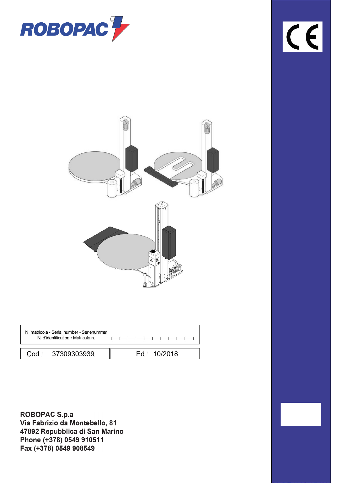
ROTOPLAT 108-308-508-708
ROTOPLAT LP 308FR-508PDS-708PVS
ROTOPLAT TP 108-308-508-708
USE AND MAINTENANCE MANUAL
ENG
Page 2

ENG
2
Page left blank intentionally
Page 3

3
Index
ENG
Index
1. GENERAL INFORMATION ................................................................................................................................. 6
1.1. PURPOSE OF THE MANUAL ............................................................................................................................. 6
1.2. MANUFACTURER AND MACHINE IDENTIFICATION ....................................................................................... 7
1.3. TERMS AND DEFINITIONS ................................................................................................................................ 8
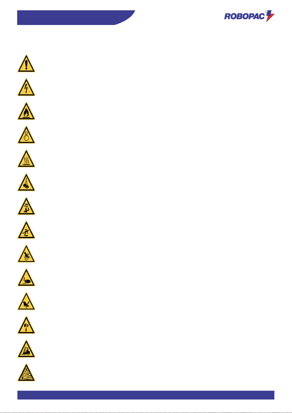
1.3.1. PICTOGRAMS INDICATING DANGER ....................................................................................................... 9
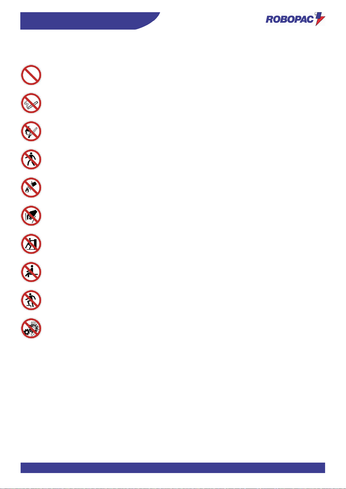
1.3.2. PICTOGRAMS INDICATING PROHIBITION ............................................................................................. 10
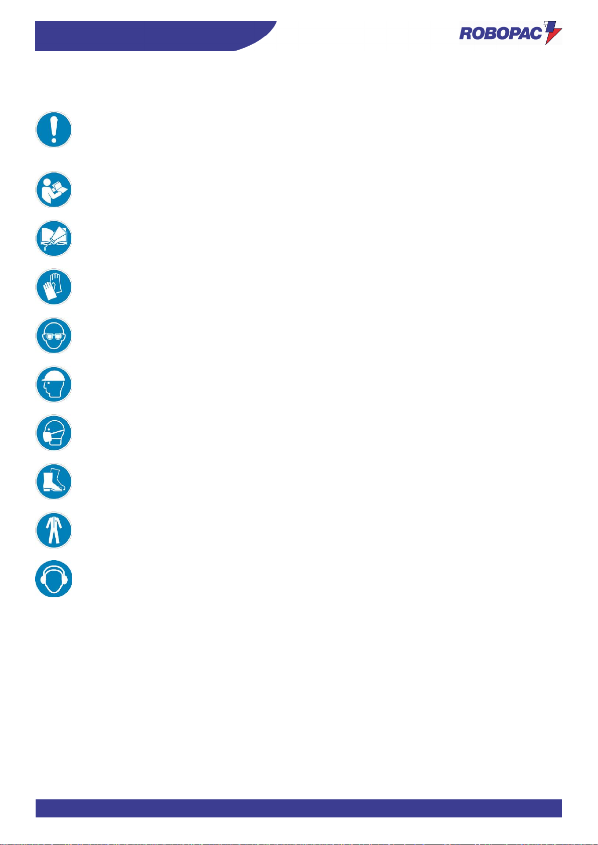
1.3.3. PICTOGRAMS INDICATING OBLIGATION ............................................................................................... 11
1.4. HOW TO REQUEST ASSISTANCE .................................................................................................................. 12
1.5. ATTACHED DOCUMENTATION ....................................................................................................................... 12
1.6. HOW TO READ THE INSTRUCTIONS FOR USE ............................................................................................ 12
2. SAFETY INFORMATION................................................................................................................................... 13
2.1. GENERAL SAFETY WARNINGS ...................................................................................................................... 13
2.2. SAFETY WARNINGS FOR HANDLING AND INSTALLATION ......................................................................... 14
2.3. SAFETY WARNINGS FOR USE AND OPERATION ........................................................................................ 15
2.4. SAFETY WARNINGS RELATED TO MISUSE .................................................................................................. 16
2.4.1. REASONABLY FORESEEABLE MISUSE ................................................................................................. 16
2.4.2. EMPLOYER OBLIGATIONS ...................................................................................................................... 16
2.5. SAFETY WARNINGS ON RESIDUAL RISKS ................................................................................................... 17
2.6. SAFETY WARNINGS FOR ADJUSTMENTS AND MAINTENANCE ................................................................ 20
2.7. SAFETY WARNING FOR THE ELECTRICAL EQUIPMENT ............................................................................ 20
2.8. INFORMATION AND SAFETY SIGNS .............................................................................................................. 21
2.9. PERIMETER AREAS ......................................................................................................................................... 23
3. TECHNICAL INFORMATION ............................................................................................................................ 24
3.1. MACHINE GENERAL DESCRIPTION ............................................................................................................... 24
3.1.1. MACHINE MODELS DESCRIPTION ......................................................................................................... 26
3.2. DESCRIPTION OF THE OPERATION CYCLE ................................................................................................. 27
3.3. SAFETY DEVICE DESCRIPTION ..................................................................................................................... 28
3.4. DESCRIPTION OF ELECTRICAL DEVICES .................................................................................................... 31
3.4.1. REMOTE CONTROL SOFTWARE ............................................................................................................ 33
3.5. DESCRIPTION OF PNEUMATIC DEVICES ..................................................................................................... 34
3.6. DESCRIPTION OF ACCESSORIES ON REQUEST ......................................................................................... 35
3.7. "ROTOPLAT 308-508-708" TECHNICAL DATA ................................................................................................ 39
3.7.1. MACHINE AND PALLET DIMENSIONS .................................................................................................... 39
3.7.2. MACHINE TECHNICAL FEATURES .......................................................................................................... 40
3.7.3. PRESSER TECHNICAL FEATURES ......................................................................................................... 40
3.7.4. PNEUMATIC CREASING HEAD TECHNICAL FEATURES ...................................................................... 40
3.7.5. SPOOL FEATURES ................................................................................................................................... 41
3.8. "ROTOPLAT LP 308 - 508 - 708" TECHNICAL DATA ...................................................................................... 42
3.8.1. MACHINE AND PALLET DIMENSIONS .................................................................................................... 42
3.8.2. MACHINE TECHNICAL FEATURES .......................................................................................................... 43
3.8.3. PRESSER TECHNICAL FEATURES ......................................................................................................... 43
3.8.4. PNEUMATIC CREASING HEAD TECHNICAL FEATURES ...................................................................... 43
3.8.5. SPOOL FEATURES ................................................................................................................................... 44
3.9. “ROTOPLAT TP3 308-508-708" TECHNICAL DATA ........................................................................................ 45
3.9.1. MACHINE AND PALLET DIMENSIONS .................................................................................................... 45
3.9.2. MACHINE TECHNICAL FEATURES .......................................................................................................... 46
3.9.3. PRESSER TECHNICAL FEATURES ......................................................................................................... 46
3.9.4. PNEUMATIC CREASING HEAD TECHNICAL FEATURES ...................................................................... 46
3.9.5. SPOOL FEATURES ................................................................................................................................... 47
3.10. NOISE LEVEL ................................................................................................................................................ 48
3.11. INSTALLATION ENVIRONMENT CHARACTERISTICS .............................................................................. 48
4. INFORMATION ON HANDLING AND INSTALLATION ...................................................................................... 49
4.1. RECOMMENDATIONS FOR HANDLING AND LOADING................................................................................ 49
4.2. PACKING AND UNPACKING ............................................................................................................................ 49
4.3. TRANSPORT AND HANDLING ......................................................................................................................... 51
4.4. HANDLING AND LIFTING ................................................................................................................................. 52
4.5. INSTALLATION OF THE MACHINE .................................................................................................................. 53
Page 4

ENG
Index
4
4.5.1. ELECTRIC BOX ASSEMBLY ..................................................................................................................... 54
4.5.2. SLIDE SHAFT ASSEMBLY ........................................................................................................................ 55
4.5.3. SLIDE SHAFT ASSEMBLY ........................................................................................................................ 56
4.5.4. LOADING/UNLOADING RAMP ASSEMBLY ............................................................................................. 57
4.5.4.1. LOADING DIRECTION MODIFICATION .......................................................................................... 58
4.5.5. PNEUMATIC PRESSER ASSEMBLY (OPTIONAL) .................................................................................. 62
4.5.6. “BUBBLE WRAP” KIT ASSEMBLY (OPTIONAL) ....................................................................................... 63
4.5.7. MECHANICAL PRESSER ASSEMBLY (OPTIONAL) ................................................................................ 64
4.6. MACHINE FIXING .............................................................................................................................................. 65
4.7. MACHINE UNDERGROUND INSTALLATION .................................................................................................. 66
4.8. RECOMMENDATIONS FOR CONNECTIONS ................................................................................................. 66
4.9. PNEUMATIC CONNECTION ............................................................................................................................. 66
4.10. ELECTRICAL CONNECTION ........................................................................................................................ 67
5. INFORMATION ON ADJUSTMENTS ................................................................................................................ 68
5.1. RECOMMENDATIONS FOR ADJUSTMENTS ................................................................................................. 68
5.2. ADJUSTING THE “CARRIAGES” ...................................................................................................................... 69
5.2.1. SPOOL CARRIAGES OF "PDS" TYPE (PRE-STRETCH GEAR REPLACEMENT) ................................. 69
5.2.2. SPOOL CARRIAGES OF "FR for mesh" TYPE ......................................................................................... 71
5.3. SPOOL CARRIAGE LIFTING CHAIN ADJUSTMENT ....................................................................................... 72
5.4. ROTARY TABLE CHAIN ADJUSTMENT .......................................................................................................... 72
5.5. “TP3” TABLE ROTATION CHAIN ADJUSTMENT ............................................................................................. 73
5.6. ADJUSTING ROTARY TABLE GEAR WHEELS ............................................................................................... 74
5.7. ADJUSTING THE TABLE GUIDE WHEELS ..................................................................................................... 75
5.8. “BUBBLE WRAP” SPOOL BRAKING ADJUSTMENT ....................................................................................... 75
6. INFORMATION ABOUT THE USE .................................................................................................................... 76
6.1. RECOMMENDATIONS FOR OPERATION AND USE ...................................................................................... 76
6.2. DESCRIPTION OF THE CONTROLS ............................................................................................................... 77
6.3. DESCRIPTION OF USER INTERFACE ............................................................................................................ 78
6.3.1. NUMERICAL AND ALPHANUMERICAL KEYBOARD ............................................................................... 81
6.3.2. PROGRAMMING WINDOW ....................................................................................................................... 82
6.4. “HOME” PAGE ................................................................................................................................................... 83
6.5. “MANUAL HANDLING” PAGE ........................................................................................................................... 85
6.5.1. MANUAL REINFORCEMENT FUNCTION ................................................................................................. 86
6.6. “RECIPES” PAGE .............................................................................................................................................. 87
6.7. “WRAPPING CYCLE” PAGE ............................................................................................................................. 88
6.8. “GENERAL PARAMETERS” PAGE ................................................................................................................... 89
6.9. “PRODUCTION COUNTERS (PALLETS)” PAGE ............................................................................................. 90
6.10. “HMI SETTINGS” PAGE ................................................................................................................................ 91
6.11. “PASSWORD CHANGE” SCREEN ............................................................................................................... 92
6.12. “ENTER PASSWORD” SCREEN (USER LOGIN)” ....................................................................................... 93
6.13. "SERVICE” SCREEN ..................................................................................................................................... 94
6.14. NEW RECIPE PROGRAMMING ................................................................................................................... 95
6.15. PHASE ANGLE ADJUSTMENT .................................................................................................................... 96
6.16. MACHINE SWITCHING ON AND OFF ......................................................................................................... 96
6.17. CYCLE PARAMETERS SETTING ................................................................................................................ 97
6.18. DESCRIPTION OF THE WRAPPING CYCLES ............................................................................................ 97
6.18.1. SINGLE WRAPPING CYCLE ................................................................................................................ 97
6.18.2. DOUBLE WRAPPING CYCLE .............................................................................................................. 97
6.18.3. WRAPPING CYCLE WITH FEEDER .................................................................................................... 98
6.19. CYCLE START AND STOP ........................................................................................................................... 99
6.20. PRESSER HEIGHT CHANGE ....................................................................................................................... 99
6.21. PNEUMATIC CYLINDER WITH ROD ......................................................................................................... 100
6.21.1. MECHANICAL PRESSER ................................................................................................................... 100
6.22. SPOOL LOADING ....................................................................................................................................... 101
6.23. “BUBBLE WRAP” SPOOL LOADING .......................................................................................................... 102
7. MAINTENANCE INFORMATION ..................................................................................................................... 103
7.1. RECOMMENDATIONS FOR MAINTENANCE ................................................................................................ 103
7.2. PERIODICAL MAINTENANCE INTERVALS ................................................................................................... 104
Page 5

5
Index
ENG
7.3. LUBRICATION POINT DIAGRAM ................................................................................................................... 106
7.4. LUBRICANT TABLE......................................................................................................................................... 108
7.5. CONDENSATE DRAINAGE ............................................................................................................................ 109
7.6. AIR FILTER CLEANING .................................................................................................................................. 109
7.7. MACHINE CLEANING ..................................................................................................................................... 110
8. FAULT INFORMATION ................................................................................................................................... 111
8.1. ALARM MESSAGES ........................................................................................................................................ 111
9. REPLACEMENT INFORMATION .................................................................................................................... 112
9.1. RECOMMENDATIONS FOR REPLACING MACHINE PARTS ...................................................................... 112
9.2. REPLACING THE ROTARY TABLE WHEELS ............................................................................................... 113
9.3. REPLACING THE ROTARY TABLE ROLLERS .............................................................................................. 114
9.4. REPLACING THE GUIDING ROLLERS .......................................................................................................... 115
9.5. REPLACING THE ROTARY TABLE GEAR WHEELS .................................................................................... 116
9.6. RECOMMENDED SPARE PARTS LIST ......................................................................................................... 117
9.7. MACHINE DECOMMISSIONING AND SCRAPPING ...................................................................................... 117
9.7.1. MACHINE DECOMMISSIONING ............................................................................................................. 117
9.7.2. MACHINE SCRAPPING ........................................................................................................................... 117
10. ANNEXES ....................................................................................................................................................... 118
10.1. WARRANTY CONDITIONS ......................................................................................................................... 118
10.2. PRESSER PNEUMATIC DIAGRAM ............................................................................................................ 119
10.3. CREASING HEAD PNEUMATIC DIAGRAM ............................................................................................... 120
Page 6
ENG
GENERAL INFORMATION
6
1. GENERAL INFORMATION
1.1. PURPOSE OF THE MANUAL
- The manual is an integral part of the machine and is aimed at providing the operator with the “Instructions for
use” in order to prevent and minimise the risks that arise from human-machine interaction.
The information has been written by the Manufacturer in Italian (the original language) in full compliance with
the professional writing principles and the regulations in force.
The communication principles were chosen according to the target readers in order to ease the reading and
understanding of the information.
The information may be translated into other languages to satisfy the legal and/or market requirements.
The manuals must be translated directly from the original instructions, without modifications.
Each translation (including that provided by the purchasing agent or by the company that introduces the
machine into the country in question) must specify the message “Translation of the original instructions”.
-
Refer to the table of contents in order to easily identify the subjects of interest.
-
Some information may not correspond completely to the actual configuration of the machine delivered.
-
Any additional information does not affect the readability of the text and the safety level.
-
The Manufacturer reserves the right to modify the contents of the manual without prior notice provided that the
safety level is not altered.
-
Every notification by the recipients can be an important contribution to the improvement of after-sales services
that the manufacturer intends to offer to its customers.
-
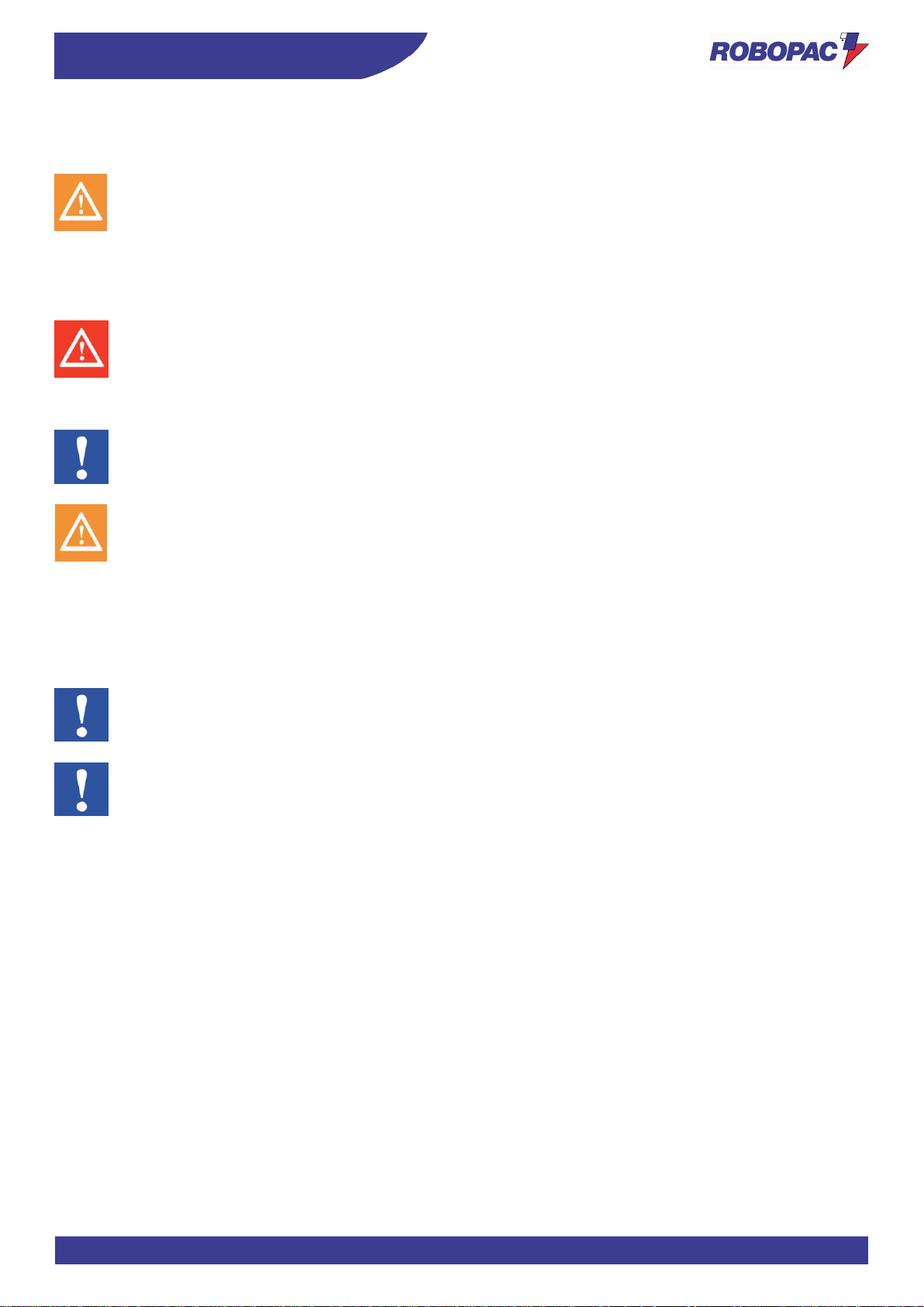
The symbols described below are used to highlight important information or specifications.
Danger - warning
The symbol indicates critically dangerous situations that if neglected can result in serious personal safety
and health hazards.
Caution - warning
The symbol indicates that suitable actions must be taken in order to avoid personal safety and health
hazards and economic damages.
Important
The symbol indicates particularly important technical and operating information that should not be
neglected.
Page 7
7
GENERAL INFORMATION
ENG
1.2. MANUFACTURER AND MACHINE IDENTIFICATION
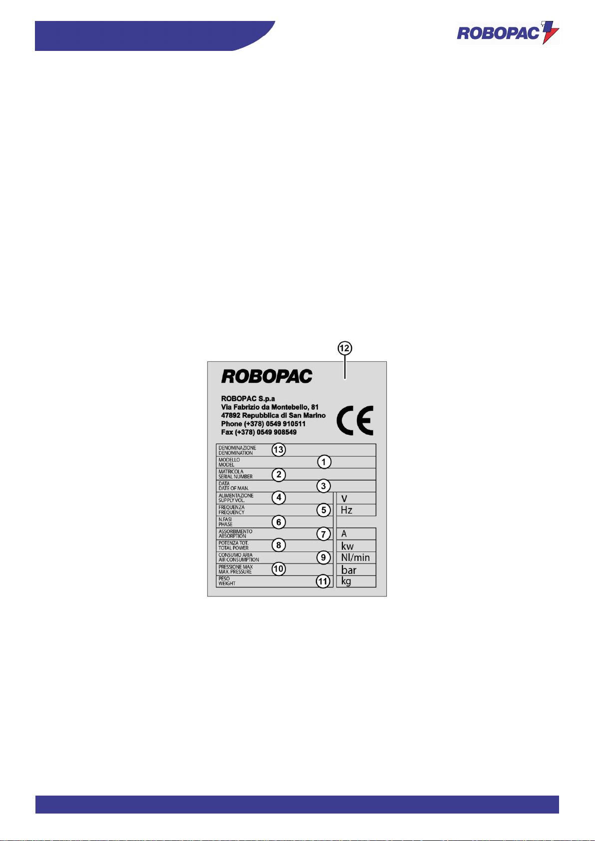
The illustrated identification plate is applied directly to the machine. It contains references and indispensable operating
safety indications.
1) Machine model.
2) Machine serial number.
3) Year of manufacture.
4) Power supply voltage.
5) Power supply frequency.
6) Power supply phases.
7) Absorbed electric current.
8) Installed power.
9) Air consumption.
10) Air supply max. pressure.
11) Machine weight.
12) Manufacturer’s identification.
13) Name.
Page 8
ENG
GENERAL INFORMATION
8
1.3. TERMS AND DEFINITIONS
Some recurring terms found within the manual are described in order to complete their meaning.
Maintenance:
The set of operations required to maintain the machine efficient and in good working order.
Normally some operations are scheduled by the manufacturer, who defines the necessary skills and
methods of intervention.
Some unscheduled operations must be performed after consulting the manufacturer.
Operator:
A person chosen and authorised among those who have the requirements, skills and information
necessary for installation, use and ordinary maintenance of the machine.
Maintenance technician:
Technician chosen and authorised among those who have the requirements to perform routine and
extraordinary maintenance on the machine. Therefore, the technician must have accurate information
and competences with particular skills in the field of intervention.
Format changeover:
Set of operations to carry out on the machine before starting to work with characteristics other than
the previous ones.
Training:
Training process aimed at transferring to the new operator the knowledge, skills and behaviours
required to operate the machine autonomously, properly and safely.
Installer:
Technician chosen and authorised by the manufacturer or by its representative, among those with the
requirements to install and test the machine or the relevant system.
Assistant:
Employee assigned to assist the production processes of the machine or system in question.
Production manager:
Qualified technician, with experience and competence in the field of machinery for the reference
sector.
Depending on the production requirements, the production manager can operate the machine directly,
or
select the operator to be assigned to the task.
Page 9
9
GENERAL INFORMATION
ENG
1.3.1. PICTOGRAMS INDICATING DANGER
The following table summarises the safety-related pictograms which indicate DANGER.
ATTENTION - GENERIC DANGER
This draws the attention of the personnel concerned to the risk of physical injuries caused by the operation
described if it is not carried out in compliance with safety regulations.
ATTENTION - DANGER DUE TO CONTACT WITH LIVE PARTS
This indicates to the personnel concerned that the described operation poses, if not carried out in
compliance with safety regulations, a risk of electric shock.
ATTENTION - DANGER DUE TO FLAMMABLE MATERIAL
ATTENTION - DANGER DUE TO MOVING PARTS
ATTENTION- DANGER DUE TO HIGH TEMPERATURES
ATTENTION - DANGER DUE TO SUSPENDED LOADS
ATTENTION - DANGER DUE TO CONTACT WITH OVERHEAD OBSTACLES
ATTENTION - TRIPPING OR FALLING DANGER
ATTENTION - TANGLING DANGER
It signals to the concerned personnel that the device bearing this pictogram features parts where there is
the risk getting tangled when accessed.
ATTENTION - HAND CRUSHING DANGER
ATTENTION - SHEARING DANGER
ATTENTION - CUTTING DANGER
It signals to the concerned personnel that the device on which the pictogram is located has sharp parts that
may injure their hands.
ATTENTION - DANGER DUE TO CARRIAGE MOVEMENT
ATTENTION - EXPLOSION DANGER
Page 10
ENG
GENERAL INFORMATION
10
1.3.2. PICTOGRAMS INDICATING PROHIBITION
The following table summarises the safety-related pictograms indicating PROHIBITION.
GENERIC PROHIBITION
NO SMOKING
Smoking is not allowed in the area where this sign is located.
NO NAKED FLAMES
This symbol prohibits the use of naked flames near the machine or parts of it to prevent a fire hazard.
NO PEDESTRIANS
Pedestrians are not allowed to pass through the area where this signal is located.
DO NOT EXTINGUISH WITH WATER
Any fire that may occur near the machine or parts of it must NOT be extinguished with jets of water.
DO NOT INSERT YOUR HANDS
DO NOT PUSH
DO NOT SEAT DOWN
DO NOT CLIMB ONTO THE SURFACE
DO NOT REMOVE THE OPERATOR GUARDS
Page 11
11
GENERAL INFORMATION
ENG
1.3.3. PICTOGRAMS INDICATING OBLIGATION
The following table summarises the safety-related pictograms indicating OBLIGATION.
GENERIC OBLIGATION
The presence of the symbol next to the description indicates the obligation to carry out the
operation/manoeuvre as described and in compliance with current safety regulations, in order to avoid
risks and/or injuries.
OBLIGATION TO REFER TO THE OPERATOR’S MANUAL
Obligation, before carrying out any operation on the machine, to read the Instruction Manual supplied with
the machine.
OBLIGATION TO USE LUBRICANTS RECOMMENDED BY IMA
Obligation, before changing the oil or the lubricants, to read the Instruction Manual supplied with the
machine.
OBLIGATION TO WEAR PROTECTIVE GLOVES
The presence of the symbol next to the description requires the use of protective gloves by the operator,
since the risk of injury is implicit.
OBLIGATION TO WEAR PROTECTIVE GOGGLES
The presence of the symbol next to the description requires the use of safety goggles by the operator,
since the risk of injury is implicit.
OBLIGATION TO WEAR A PROTECTIVE HELMET
The presence of the symbol next to the description requires the use of a protective helmet by the operator
since the risk of injury is implicit.
OBLIGATION TO WEAR A PROTECTIVE MASK
The presence of the symbol next to the description requires the use of a respiratory protective mask by the
operator, since the risk of injury is implicit.
OBLIGATION TO WEAR SAFETY SHOES
The presence of the symbol next to the description requires the use of protective shoes by the operator,
since the risk of injury is implicit.
OBLIGATION TO WEAR PROTECTIVE CLOTHING
The presence of the symbol next to the description requires the use of a protective overall by the operator,
since the risk of injury is implicit.
OBLIGATION TO WEAR EARMUFFS FOR PROTECTION AGAINST NOISE
The presence of the symbol next to the description requires the use of earmuffs by the operator as the risk
of injury is implicit.
Page 12

ENG
GENERAL INFORMATION
12
1.4. HOW TO REQUEST ASSISTANCE
Robopac distribution network is at your disposal for any problem regarding technical assistance, spare parts and any
new requirement you might need for your business.
For every technical service request regarding the machine, please indicate the data found on the identification plate,
the approximate hours of use and the type of fault detected.
Please refer to one of the authorised service centres or directly to the address indicated for any need.
ROBOPAC S.p.A
VIA FABRIZIO DA MONTEBELLO, 81
47892 GUALDICCIOLO REPUBLIC OF S. MARINO (RSM)
Tel. 0549 (international ++378) 910511
Fax 0549/908549 - 905946
htpp://www.aetnagroup.com
1.5. ATTACHED DOCUMENTATION
The machine is provided with the documentation listed below, unless otherwise agreed.
-
EC DECLARATION OF CONFORMITY.
- Warranty conditions.
- Pneumatic diagram.
-
Wiring diagram and list of components.
-
Manuals of installed commercial devices (if necessary for machine use).
-
Unpacking and installation instructions.
- Quick guide for quick start.
-
USB pendrive containing the information listed below.
•
Use and maintenance manual translated into various languages.
•
Spare parts catalogue.
• Machine programming software.
•
Wiring Diagrams.
1.6. HOW TO READ THE INSTRUCTIONS FOR USE
The manual is divided into chapters, each of which describes a specific category of information.
Important
Every operator who interacts with the machine, in addition to reading all the documentation, must read
and learn the information that falls within his/her operational competence.
Refer to the abbreviation that precedes the title of the chapters in the index, to search for topics to consult.
These instructions are the result of an automatic system that assembles text and illustrations, so it is possible that
when changing pages, there might be interruptions in the flow of text and tables.
Important
Keep this manual for the entire duration of the machine useful life in a well known and easy to access
place, available for reference any time the need should arise.
Page 13
13
SAFETY INFORMATION
ENG
2. SAFETY INFORMATION
2.1. GENERAL SAFETY WARNINGS
Caution - warning
Carefully read the “Instructions for use” specified in the manual and those applied directly to the machine.
It is important to dedicate a little time to read the “Instructions for use” in order to minimise the risks and
avoid unpleasant accidents.
Before performing any operation, the operator must make sure that he/she has understood the
“instructions for use”.
Danger - warning
Pay attention to the safety warnings, do not misuse the machine and assess the possible residual risks.
Caution is essential.
Safety is also in the hands of those who interface with the machine throughout its life span.
Important
Sometimes, accidents can be caused by a “careless” use of the machine by the operator.
Usually it is too late to remember what should have been done when the accident has already happened.
Caution - warning
Preserve the readability of the information signs and observe the indications given.
The information signs may have different shapes and colours, indicating hazards, obligations, prohibitions
and indications.
Tampering with the safety devices and the removal of the same may create risks (even severe) for the
operators.
The personnel authorised to carry out any operation with the machine must have acknowledged
experiences in the specific field.
Important
The manufacturer is not responsible for any damage to the packaged product occurred during wrapping,
stabilisation and following operations.
Important
Non-compliance with the instructions given may cause risks to the safety and health of people, as well as
economic damages.
Page 14

ENG
SAFETY INFORMATION
14
2.2. SAFETY WARNINGS FOR HANDLING AND INSTALLATION
Danger - warning
The personnel authorised to handle the machine (load and unload) must possess the necessary technical
and professional knowledge and skills.
Handle (load and unload) the machine according to the instructions affixed directly to the machine, to the
package and in the user manual.
During handling use one or more assistants, if required. This may pose unexpected risks.
In order to minimise the risks related to assistants’ involvement, you must inform them in advance on the
type of work to be carried out and the behaviour to adopt.
Handling must be carried out with the aid of specific means (crane, forklift truck etc.) by qualified
personnel capable of observing the safety requirements.
When using the lifting means, insert and/or fasten the devices (hooks, forks etc.) only into the points
provided on the package and/or on the machine.
Transport the machine with suitable means of adequate capacity.
The minimum and maximum temperature (during transport and/or storage) must fall within the range
allowed in order to prevent damaging the electrical components.
Install the machine only in spaces with no explosion and/or fire risks.
Avoid spaces exposed to atmospheric and corrosive agents.
Assess, prior to installation, if it is necessary to implement a “safety plan” in order to protect the safety of
the personnel involved.
Provide proper safety conditions when operating in high areas that are dangerous or hard to access.
Install the machine according to the minimum perimeter spaces indicated by the Manufacturer and the
surrounding working activities.
Prepare a machine installation project if the machine is to interact (directly or indirectly) with another
machine or with a production line.
The project must take into account all operating conditions, in order to comply with all laws in force on
matter of safety in the workplace.
Check that the installation space is properly ventilated in order to avoid unhealthy air concentration for the
operators.
Implement the most suitable solutions to minimise noise emission levels and acoustic pollution.
Carry out the electrical connections in accordance with the best practice and in full compliance with the
instructions provided by the Manufacturer and the specific regulations in force.
Important
The electrical connections must be carried out exclusively by operators with acquired and acknowledged
skills in the field of intervention.
The installer must test the machine and check, through a general test, that the machine can be
commissioned without any risk for the operator.
Dispose of all the packaging components in compliance with the standards in force in the Country of
installation.
Non-compliance with the instructions given may cause risks to the safety and health of people, as well as
economic damages.
Page 15
15
SAFETY INFORMATION
ENG
2.3. SAFETY WARNINGS FOR USE AND OPERATION
Danger - warning
The operator must be trained and possess the adequate skills required to carry out the specific tasks and
must be fit to use the machine safely.
When using the machine for the first time, the operator must read the manual and identify the control
functions and simulate some operations, especially machine start and stop.
The machine has been designed and manufactured to meet all the operating conditions indicated by the
Manufacturer.
Caution - warning
Use the machine only with the original safety devices installed by the Manufacturer.
Do not tamper with, disable, remove or bypass the safety devices installed on the machine.
Danger - warning
Do not modify the constructive and functional characteristics of the machine in any way.
Do not use the machine with the safety devices not properly installed and efficient.
Always wear the Personal Protective Equipment indicated in the “Instructions for use”, in particular safety
shoes, and that provided for by the laws in force on matter of safety in the workplace.
Always keep the perimeter areas in suitable conditions and free from obstacles in order to minimise the
risks for the operator, especially near the control station.
The machine must be used by one operator only, that must be appointed and authorised by the employer.
The involvement of one or more assistants when performing some operations or maintenance (ordinary)
interventions may pose unpredictable risks.
In order to minimise the risks related to assistants’ involvement, you must inform them in advance on the
type of work to be carried out and the behaviour to adopt.
Make sure that no unauthorised persons are within the machine operating area during its production
activity and during maintenance.
It is forbidden to climb onto the rotary table with forklift trucks. In addition to being dangerous, it can also
damage the machine.
Important
Non-compliance with the instructions given may cause risks to the safety and health of people, as well as
economic damages.
Page 16

ENG
SAFETY INFORMATION
16
2.4. SAFETY WARNINGS RELATED TO MISUSE
2.4.1. REASONABLY FORESEEABLE MISUSE
-
The reasonably foreseeable misuse is: “the use of the machine in a way other than that indicated in the
manual, that may stem from the easily predictable human behaviour”.
The machine must be used only for wrapping and stabilising products with regular shape or with a shape that
ensures a stable wrapping.
Packages containing liquids or insubstantial materials must have characteristics suitable to the product and be
perfectly closed and sealed to prevent the contents from flowing out.
Do not palletize or wrap products housed in irregularly shaped packages (boxes, liquid containers, etc.) or
packages that do not guarantee their stability.
-
The machine should only be used for the uses intended by the Manufacturer.
-
Do not allow the machine to be used by operators that are not properly trained, informed and authorised.
-
Packages containing liquid or insubstantial products must ensure that they do not leak out.
-
Do not wrap bulk products of irregular shape and improperly collected to avoid an unsuitable palletization.
-
Do not use the machine to wrap and stabilise living beings (animals and persons).
-
Do not use the machine with wrapping material other than that provided by the Manufacturer.
-
Do not use the machine as a lifting device or as a work surface (e.g. workbench).
-
Do not stretch or pre-stretch the film excessively and do not wrap the product with too many wrappings in
order to prevent damaging the packages and the products contained in them.
-
Do not use or let the machine be used for purposes or in ways other than those intended by the Manufacturer.
-
Do not use or let the machine be used with defective, deactivated and/or incorrectly installed safety devices.
-
Do not continue to use the machine if malfunctions have been detected.
-
Stop the machine immediately and restart it only after the normal conditions of use have been restored.
-
Never carry out an intervention with the machine in operation, but only after stopping it properly, under safety
conditions.
-
Never use the machine without wearing the Personal Protective Equipment indicated by the Manufacturer and
provided for by the laws in force on workplaces.
-
Never use the machine if the scheduled maintenance interventions have not been carried out.
-
Do not clean or wash the machine with aggressive products to avoid damaging the components.
-
Do not replace the components with non-original spare parts or part with different design and construction
features.
-
Do not leave the machine unattended at the end of the production activity without shutting it down first in
safety conditions.
2.4.2. EMPLOYER OBLIGATIONS
-
The operator must be trained to acquire the required skills in the field of packaging machines or equivalent.
Upon completing the training, ensure that the operator has understood the entire content of the operating
manual, in particular the safety information.
-
The operator must have the required skills and must be fit for the activities to be carried out in safety
conditions.
-
The employer must inform the operator on the reasonably foreseeable misuses and on the persistent residual
risks.
-
The operator must be capable of reading and understanding the user manual and must easily identify the
safety signs.
-
Allow the machine to be used only by operators that are properly trained, informed and authorised.
Important
The employer must document the training carried out for the operators.
Page 17
17
SAFETY INFORMATION
ENG
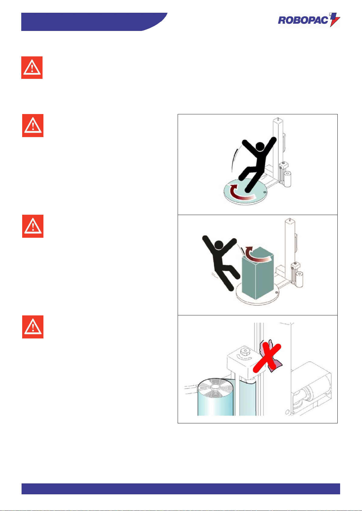
2.5. SAFETY WARNINGS ON RESIDUAL RISKS
Danger - warning
During design and manufacturing, the Manufacturer has paid particular attention to the residual risks that
may affect the safety and health of the operators.
The residual risks are: “all the risks that persists although all safety solutions have been applied and
integrated during machine design”.
The list specifies the residual risks specific for this type of machine.
Risk of slipping:
Do not climb on machine parts during its
operation.
Risk of impact:
Do not approach machine parts during its
operation.
Risk of shearing upper limbs:
Do not insert your hands inside moving parts.
Page 18
ENG
SAFETY INFORMATION
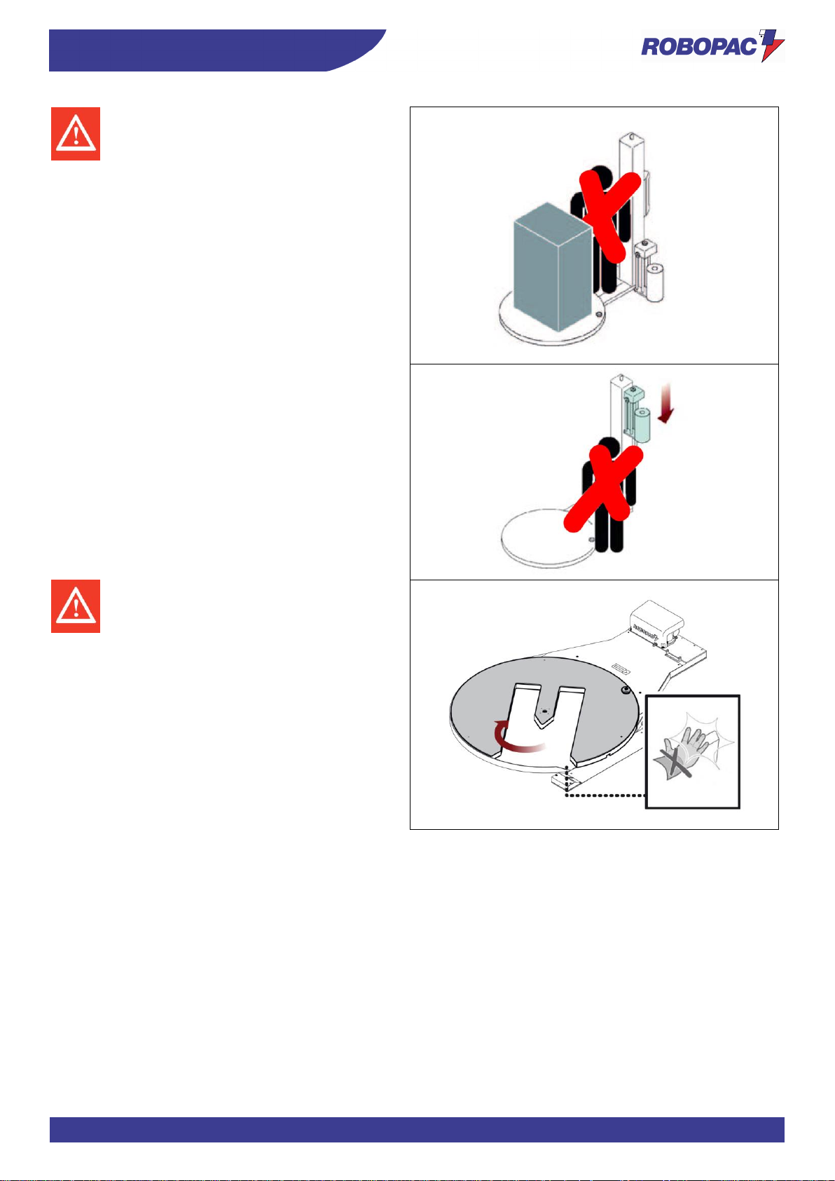
18
Risk of body crushing:
Do not stand in the machine operating area.
Risk of crushing upper limbs:
Do not insert your hands inside moving parts.
Page 19
19
SAFETY INFORMATION
ENG
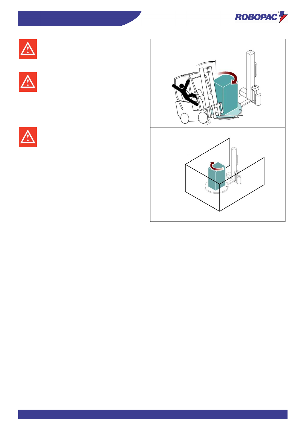
Risk of impact and slipping:
Do not approach or climb on machine parts
(e.g.: rotary table) with the lifting device
during machine operation.
Risk of falling or ejected objects:
Do not use the machine at a speed which is
not suitable for the type of product to be
wrapped.
If the packages to be wrapped contain
unstable and dangerous elements, it is
necessary to implement appropriate safety
measures (e.g.: perimeter protections) to
avoid risks of injuries to persons.
Page 20

ENG
SAFETY INFORMATION
20
2.6. SAFETY WARNINGS FOR ADJUSTMENTS AND MAINTENANCE
- Keep the machine in maximum efficiency conditions and perform all the scheduled maintenance operations
provided for by the Manufacturer.
Proper maintenance will provide the best performance, a longer life span and constant compliance with safety
requirements.
- Enable all machine safety devices before performing any maintenance and adjustment operations.
- Demarcate the surrounding areas and put in place adequate safety measures, as provided for by the
standards on workplace safety, in order to prevent and minimise the risks.
- Maintenance interventions in areas that are not easily accessible or dangerous must be carried out after
having ensured the necessary conditions are met.
- The personnel authorised to carry out the ordinary maintenance (adjustments, replacements etc.) must
possess the necessary technical and professional knowledge and skills.
- Do not carry out interventions other than those indicated in the user manual without the express authorisation
of the Manufacturer.
- Do not use products that contain corrosive and flammable substances or that are harmful to people's health.
- Wear Personal Protective Equipment as required by labour laws and as indicated in the "Instructions for Use"
and/or on the machine.
- The use of similar but non-original spare parts may result in improper repairs, altered performance and
economic damage.
- Use lubricants (oils or grease) recommended by the Manufacturer or with similar chemical-physical features.
- Do not dispose of polluting liquids, worn parts and maintenance waste into the environment.
- Select the components according to the chemical and physical features of the material and dispose of them
separately in accordance with the applicable laws.
- All the extraordinary maintenance interventions shall be carried out only by authorised personnel with
experience and expertise in the field of intervention.
Important
Non-compliance with the instructions given may cause risks to the safety and health of people, as
well as economic damages.
2.7. SAFETY WARNING FOR THE ELECTRICAL EQUIPMENT
The electrical equipment has been designed and manufactured in accordance with the relevant standards.
These standards consider operating conditions based on the surrounding environment.
The list contains the conditions necessary for the correct operation of the electrical equipment.
- Ambient temperature must be within 5°C and 40°C.
- The relative humidity should be between 50% (measured at 40°C) and 90% (measured at 20°C).
- The installation environment must be immune to and must not be a source of electromagnetic interference or
radiation (x-rays, lasers, etc․).
- The environment must not have areas with concentrations of gas and dust that are potentially explosive and/or
with a fire risk.
- The products and materials used during production and maintenance must not contain contaminants or
corrosive agents (acids, chemicals, salts, etc․) and must not be able to penetrate and/or come into contact
with electrical components.
- During transport and storage, the ambient temperature must be between -25°C and 55°C.
- The electrical equipment may still be exposed to a temperature of up to 70°Cprovided that the exposure time
does not exceed 24 hours.
- The electrical equipment operates correctly up to 1000 m above sea level.
Important
If it is not possible to comply with one or more of the conditions listed, which are essential for the correct
operation of the electrical equipment, it is necessary to agree at the contractual stage which additional
solutions to adopt in order to create the most suitable conditions (e.g. specific electrical components, air
conditioning equipment, etc․).
Page 21

21
SAFETY INFORMATION
ENG
2.8. INFORMATION AND SAFETY SIGNS
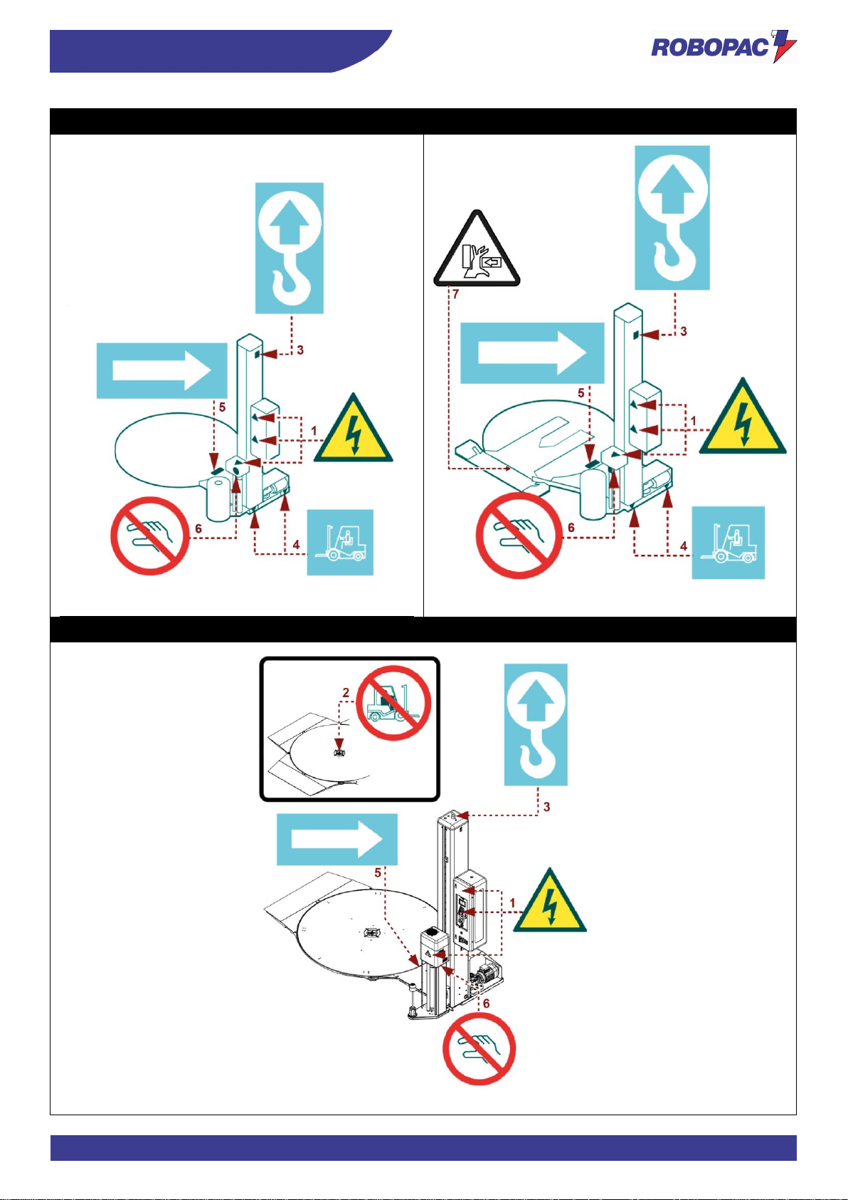
The figure indicates the position of the safety and information signs affixed to the machine.
For each sign the relative description is specified.
1. Electrical hazard sign
Do not access the area to avoid risks of electric shock or electrocution.
2. Prohibition sign
Do not climb on the ramp with the forklift truck.
3. Information sign
It indicates the lifting points with hook device.
4. Information sign
It indicates the lifting points with fork device.
5. Information sign
It indicates the rotary table rotation direction.
6. Prohibition sign
Do not act on the component with your hands.
7. Danger sign
Hand crushing danger.
Important
Make sure that the nameplates are clearly legible.
If not, replace and reposition them at the original position.
Page 22
ENG
SAFETY INFORMATION
22
Rotoplat 308-508-708
Rotoplat TP3 308-508-708
Rotoplat LP 308-508-708
Page 23
23
SAFETY INFORMATION
ENG
2.9. PERIMETER AREAS
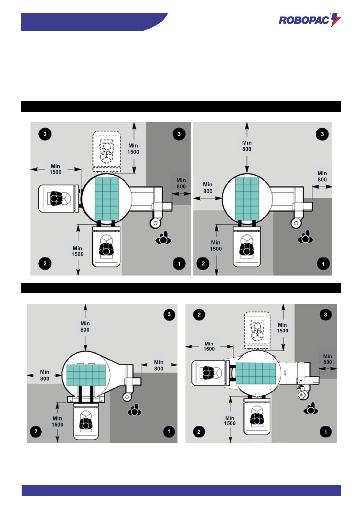
The illustration shows the perimeter working areas of the machine.
1. Operator standing area.
2. Pallet loading/unloading area.
3. Perimeter area.
Rotoplat 308-508-708
Rotoplat TP3 308-508-708
#Rotoplat LP 308-508-708
Page 24

ENG
TECHNICAL INFORMATION
24
3. TECHNICAL INFORMATION
3.1. MACHINE GENERAL DESCRIPTION
- The machine is a semi-automatic machine for palletised load wrapping and stabilising with stretch film.
- The machine must be used only for wrapping and stabilising products contained in packages (in boxes, liquid
containers, etc.) with regular shape or with a shape that ensures a stable palletisation.
- Packages containing liquids or insubstantial materials must have characteristics suitable to the product and be
perfectly closed and sealed to prevent the contents from flowing out.
- The machine consists of a rotary table, which makes the pallet turn, and a spool carriage which unwinds and
stretches the film.
- The machine is equipped with a series of safety devices designed to avoid any injuries to the operator or other
persons using the machine. It comes in different models to satisfy different market needs.
- Stretch film spools commonly available on the market are used for load wrapping.
- This machine is normally installed in workshops or industrial environments protected from the atmospheric
agents.
Danger - warning
Using this machine in explosive environments or when exposed to atmospheric agents is strictly forbidden.
- The pallet loading and unloading are performed by the user, who can also insert and cut the film.
- Only one operator is required for its use.
Page 25
25
TECHNICAL INFORMATION
ENG
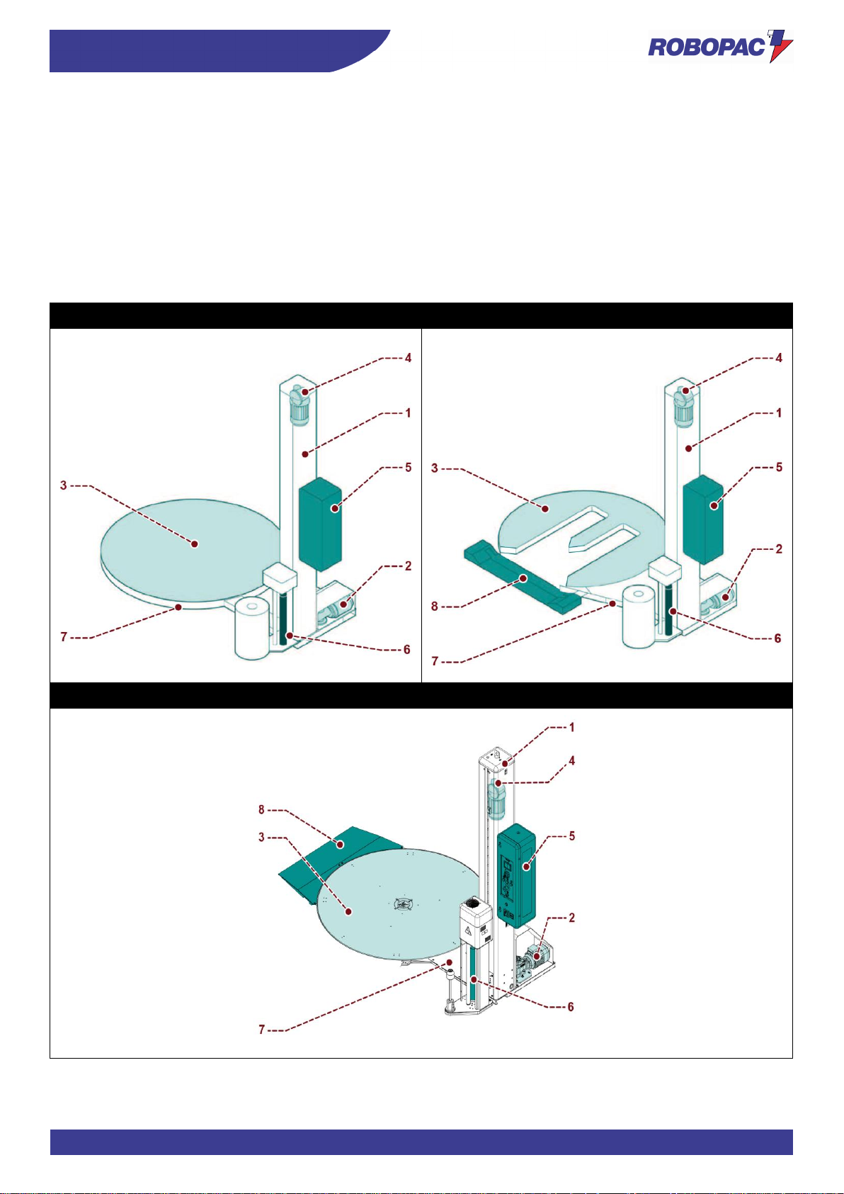
The illustration shows, for information purposes only, the machine models, and the legend lists the parts.
Legend:
1. Slide shaft
2. Table motor
3. Rotary table
4. Carriage motor
5. Control panel
6. Spool carriage
7. Base
8. Loading/unloading ramp
Rotoplat 308-508-708
Rotoplat TP3 308-508-708
Rotoplat LP 308-508-708
Page 26
ENG
TECHNICAL INFORMATION
26
3.1.1. MACHINE MODELS DESCRIPTION
Machine models
General features
Rotoplat 308
Rotoplat LP 308
Rotoplat TP3 308
Rotoplat with spool carriage of “FR” type.
Rotoplat 508
Rotoplat LP 508
Rotoplat TP3 508
Rotoplat with spool carriage of “PDS” type.
Rotoplat 708
Rotoplat LP 708
Rotoplat TP3 708
Rotoplat with spool carriage of “PVS” type.
Table: Spool carriage features
Spool carriage type
General features
FR
Spool carriage of “FR” type with friction roller, electromagnetic brake and film stretch
adjustment from control panel.
PDS
Spool carriage of “PDS” type with motorised pre-stretching rollers and electronically
controlled film tensioning.
Pre-stretch can be adjusted from the control panel (0÷25).
PVS
Spool carriage of “PVS” type with dual-motor pre-stretching rollers and electronically
controlled film tensioning.
Pre-stretch can be adjusted from the control panel (150%÷400%).
Page 27
27
TECHNICAL INFORMATION
ENG
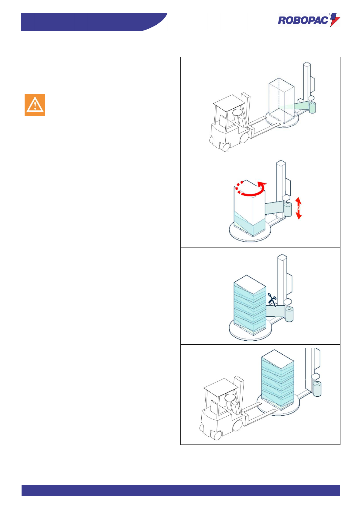
3.2. DESCRIPTION OF THE OPERATION CYCLE
Phase 1
The pallet is loaded on the rotary table against the
bracket on the plate and the operator ties the film ends
in the striker bracket slot.
Caution - warning
Risk of crushing upper limbs.
Do not insert the film in the gripper by hand.
Phase 2
Once the cycle has started, the rotary table starts to
turn, while the spool carriage unwinds the film for the
entire height, according to pre-set parameters.
Phase 3
Once the wrapping phase has ended, the machine
stops and film hot cutting and welding are automatically
performed (CW version).
Phase 4
The operator unloads the pallet.
The cycle is complete and the machine is ready to start
a new cycle.
Page 28

ENG
TECHNICAL INFORMATION
28
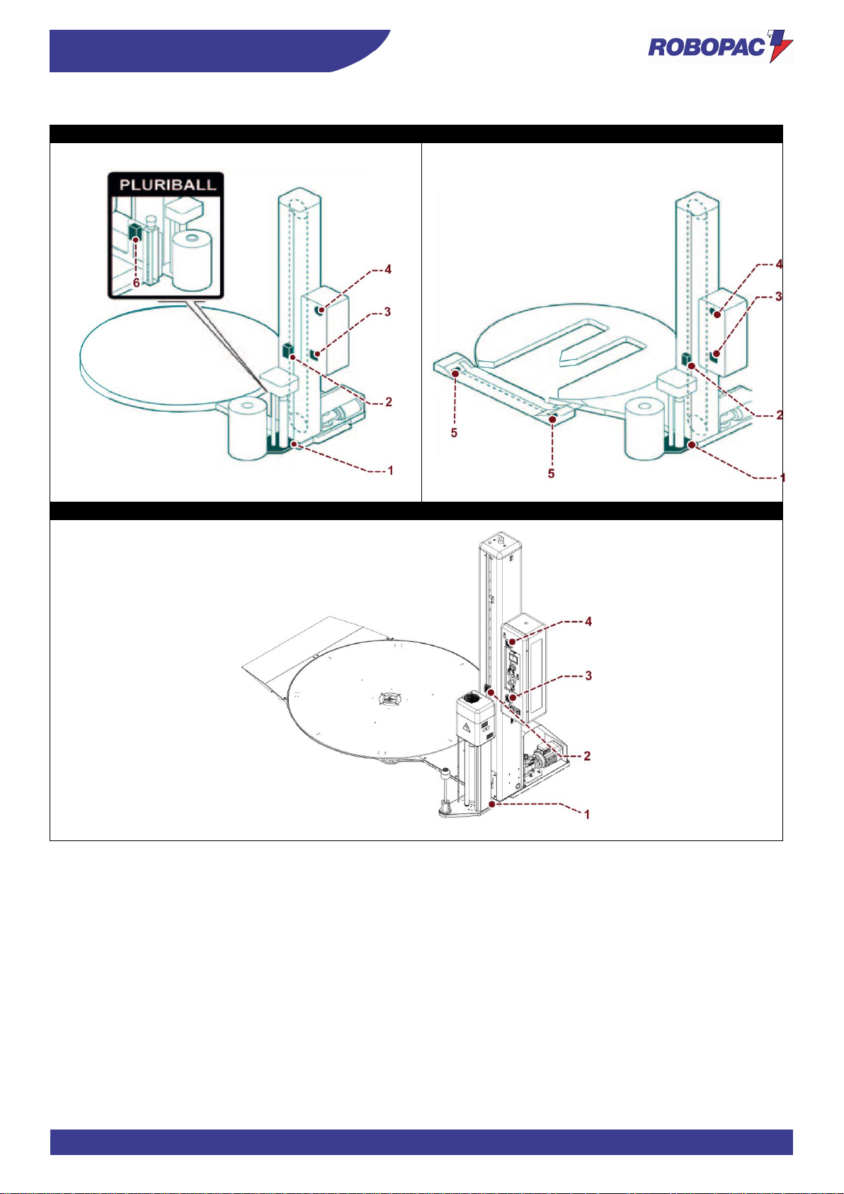
3.3. SAFETY DEVICE DESCRIPTION
The figure shows the position of the devices on the machine.
1. Spool carriage base microswitch:
it stops the downstroke if there are obstacles under the carriage.
2. Spool carriage mechanical locking device:
it immediately stops the fall of the spool carriage in case of accidental breakage of the lifting chain.
3. Main switch:
it enables and disables the power supply. It can be locked to prevent unauthorised persons from enabling it
during machine adjustment and maintenance phases.
4. Acoustic signal: it signals the wrapping cycle start.
5. Fork infeed safety photocell: it detects the presence of forks on the pallet loading/unloading ramp, stopping the
table rotation.
6. “Bubble wrap” carriage microswitch:
it stops the downstroke if there are obstacles under the spool carriage.
Page 29
29
TECHNICAL INFORMATION
ENG
Rotoplat 308-508-708
Rotoplat TP3 308-508-708
Rotoplat LP 308-508-708
Page 30
ENG
TECHNICAL INFORMATION
30
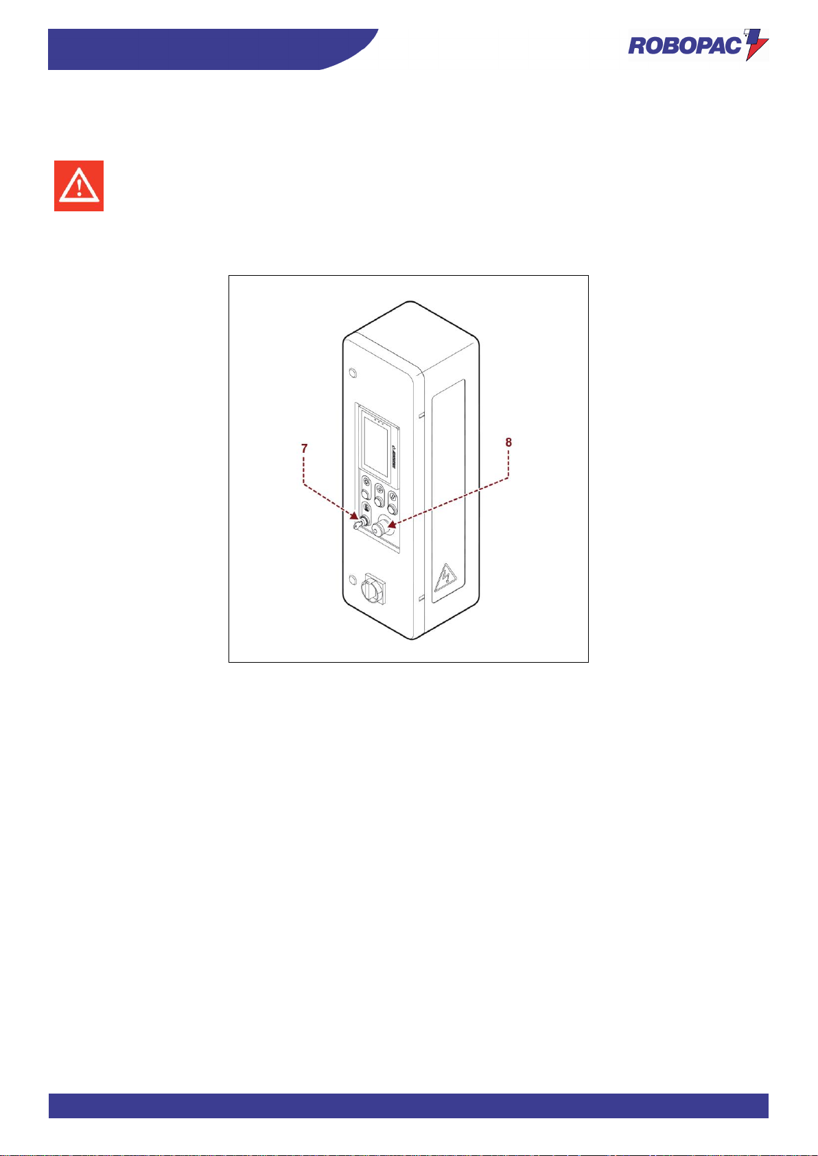
7. Emergency button:
when pressed, it immediately stops the machine in emergency conditions.
To reset, rotate the button in the direction indicated by the arrow.
Danger - warning
When the emergency button is pressed, the terminals of the motors may still be powered.
8. Key-operated switch:
it overrides the emergency condition of the spool carriage.
If it is kept turned, it allows to activate the carriage upstroke with the user interface manual controls.
Page 31

31
TECHNICAL INFORMATION
ENG
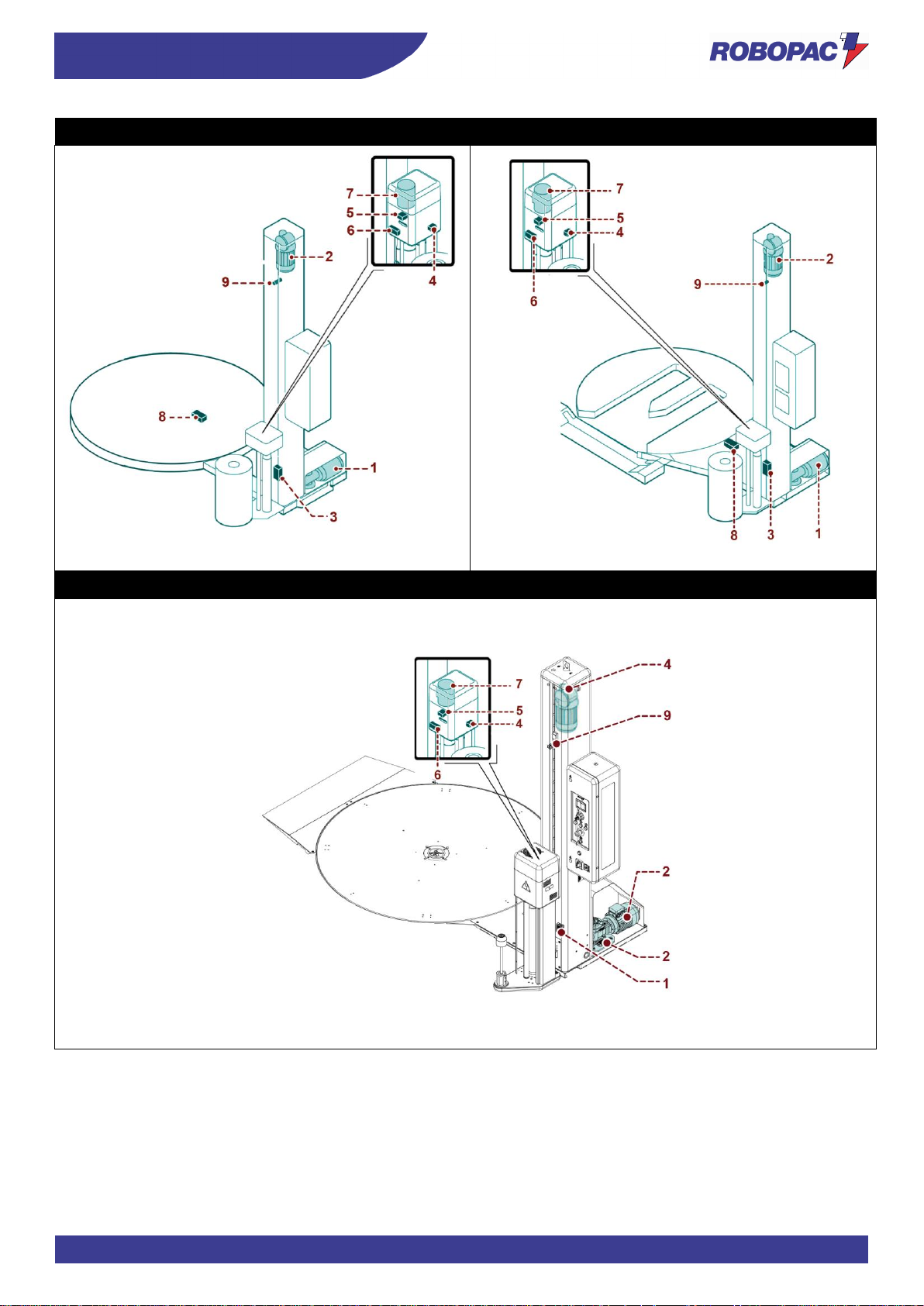
3.4. DESCRIPTION OF ELECTRICAL DEVICES
The figure shows the position of the devices on the machine.
1. Gearmotor:
it activates the table rotation.
2. Gearmotor:
it activates the spool carriage movement.
3. Carriage limit microswitch:
it is activated when the spool carriage reaches the minimum and maximum wrapping height.
4. Microswitch:
it stops the downstroke if there are obstacles under the spool carriage.
5. Photocell:
it detects the height and the presence of the load to be wrapped.
6. “Load cell” sensor:
it detects the film tensioning and enables the variation of the pre-stretching roller speed.
7. Electric motor:
it powers pre-stretching rollers.
8. Sensor:
it enables the synchronised stop of the rotary table.
9. Carriage lifting sensor:
it determines the position in which the carriage must be stopped to start the processing.
Important
For further details see the wiring diagram.
Page 32
ENG
TECHNICAL INFORMATION
32
Rotoplat 308-508-708
Rotoplat TP3 308-508-708
Rotoplat LP 308-508-708
Page 33
33
TECHNICAL INFORMATION
ENG
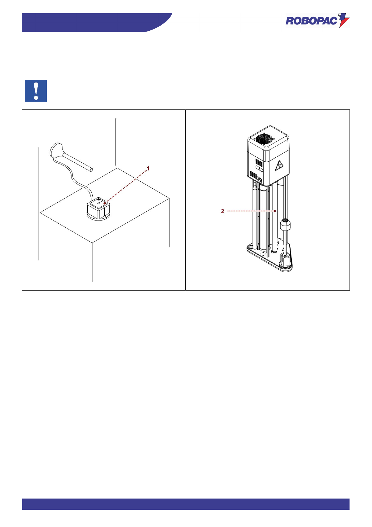
3.4.1. REMOTE CONTROL SOFTWARE
The Machine features a remote control Software (1).
Through a sensor on the roller (2), the system controls film use, end of the spool and general info.
Important
For further details see the wiring diagram.
Page 34
ENG
TECHNICAL INFORMATION
34
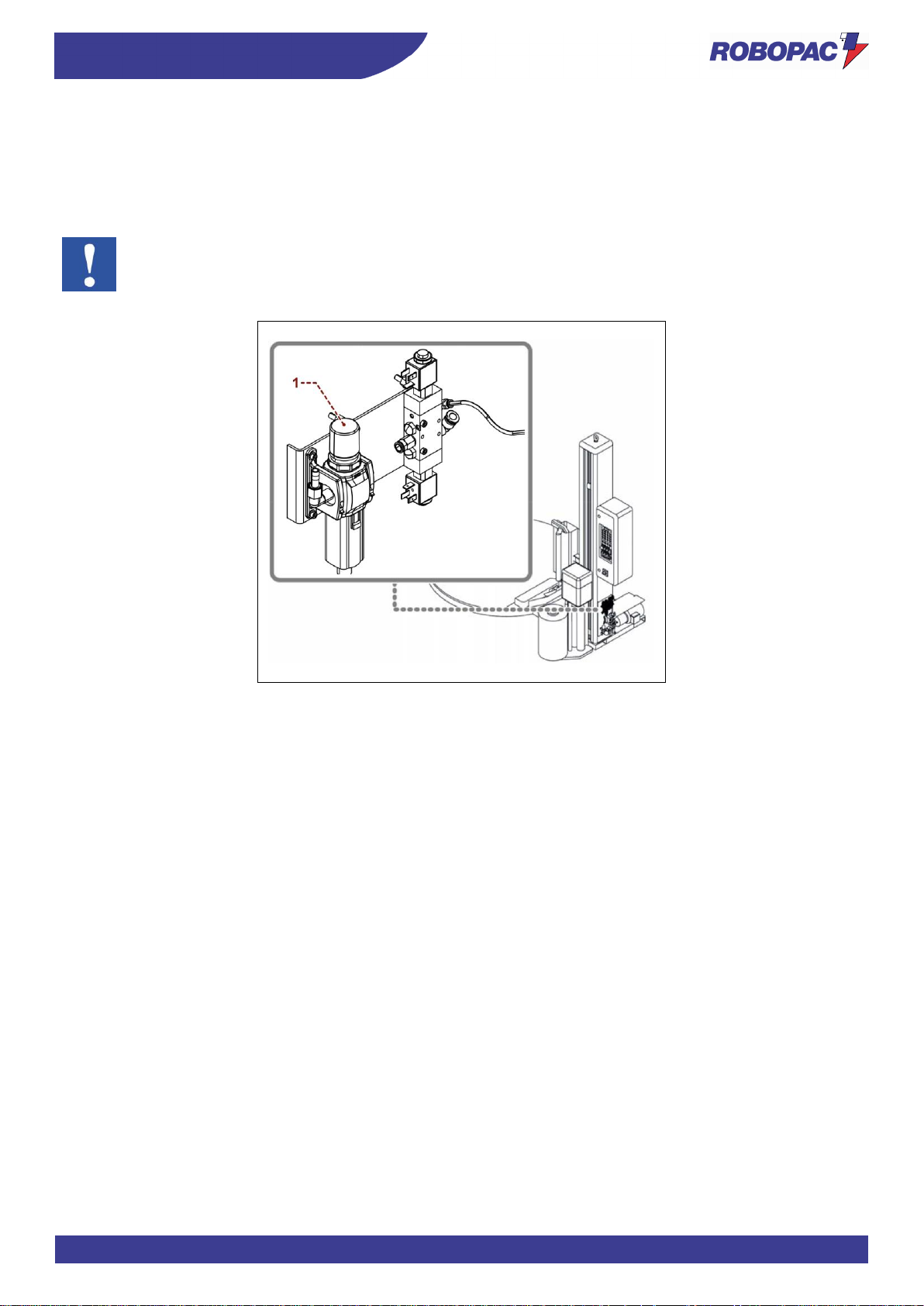
3.5. DESCRIPTION OF PNEUMATIC DEVICES
The figure shows the position of the devices on the machine.
1. Pressure regulator with filter and pressure gauge
To adjust the general pressure of the pneumatic system.
Turn the knob to change the pressure values indicated on the pressure gauge.
Important
For further details see the pneumatic diagram.
Page 35
35
TECHNICAL INFORMATION
ENG
3.6. DESCRIPTION OF ACCESSORIES ON REQUEST
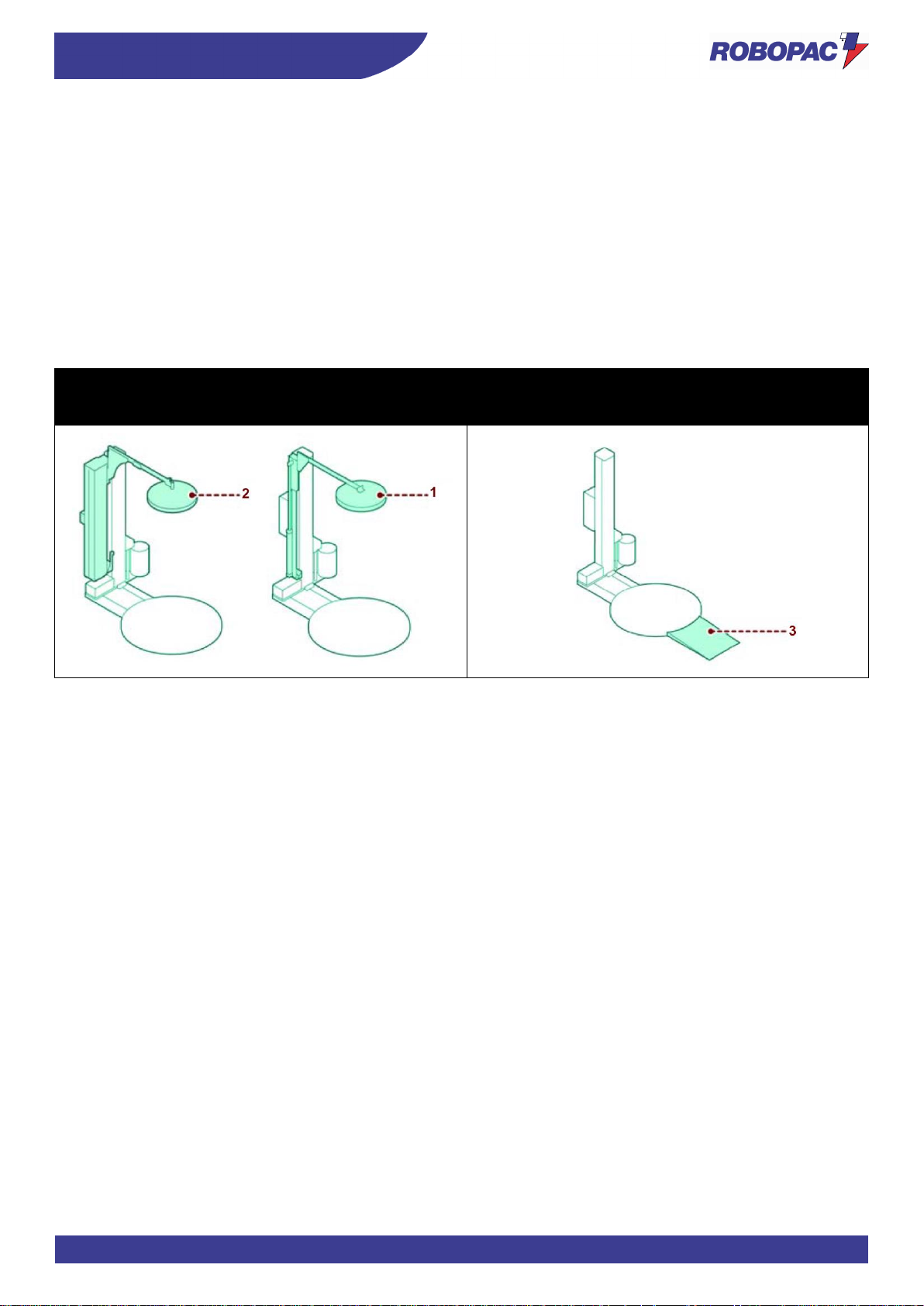
To increase the machine performance and versatility, the Manufacturer makes available the following accessories.
1. Pneumatic presser:
pneumatically controlled device for load stabilisation. It is supplied with pneumatic cylinder with rod (Max.
stroke 800 mm).
The height must be adjusted according to the size of the product to be wrapped.
An air supply system is required for its operation.
2. Mechanical presser:
electrically controlled device for load stabilisation, it is not necessary to adjust the height according to the size
of the product to be wrapped.
3. Pallet loading/unloading ramp:
it facilitates these operations through fork lifting devices (hand pallet trucks).
Rotoplat 308-508-708
Rotoplat TP3 308-508-708
Rotoplat LP 308-508-708
Rotoplat 308-508-708
Page 36
ENG
TECHNICAL INFORMATION
36
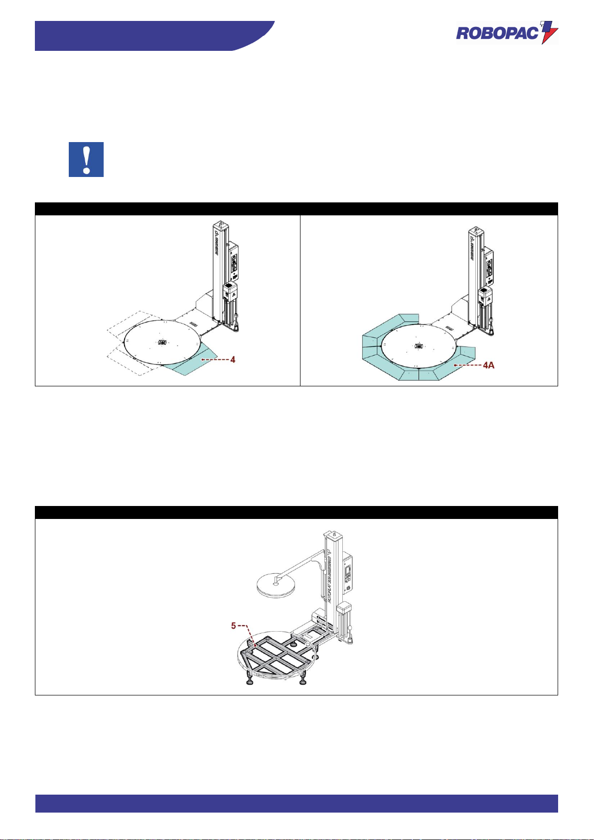
4. Pallet loading/unloading ramps:
one ramp (4) is supplied as a standard and can be placed in 5 positions (every 45°).
It is possible to purchase a second and a third optional ramp or a 270° ramp (4A) (3 pieces) which covers all
the positions.
Important
During pallet loading/unloading operations it is recommended not to get on the ramps with the
forklift truck.
Rotoplat LP 308-508-708
Rotoplat LP with 270° ramp
5. Lifting frame:
Structure which allows lifting the machine from the ground when the floor must be washed or for loading with
electric hand pallet trucks.
- Underground installation template:
profiled structure for base underground installation.
- Slide shaft (2400 - 2800 - 3100 mm):
it is used to wrap pallets which are higher than the standard ones.
Rotoplat 308-508-708
Page 37
37
TECHNICAL INFORMATION
ENG
6. “Bubble wrap” spool carrying unit:
suitable for wrapping edges or sides, using bubble wrap spools or similar ones. It features film “quick loading”
and a safety device to stop the carriage.
- Template:
Profiled structure for base underground installation.
- Rotary table (ø 1800, ø 2200, ø 2400, ø 1800 “longer”):
it is used to wrap pallets with a size greater than the standard one.
- Brake shaft for mesh (only for “FRD” spool carriages):
it is used to obtain a correct tensioning of the mesh.
- Slide shaft (2400 - 2800 - 3100 mm):
it is used to wrap pallets which are higher than the standard ones.
- Automatic cutting device:
it automatically cuts the film at the end of the cycle.
(Only for machines “Rotoplat - Rotoplat TP3 508-708”).
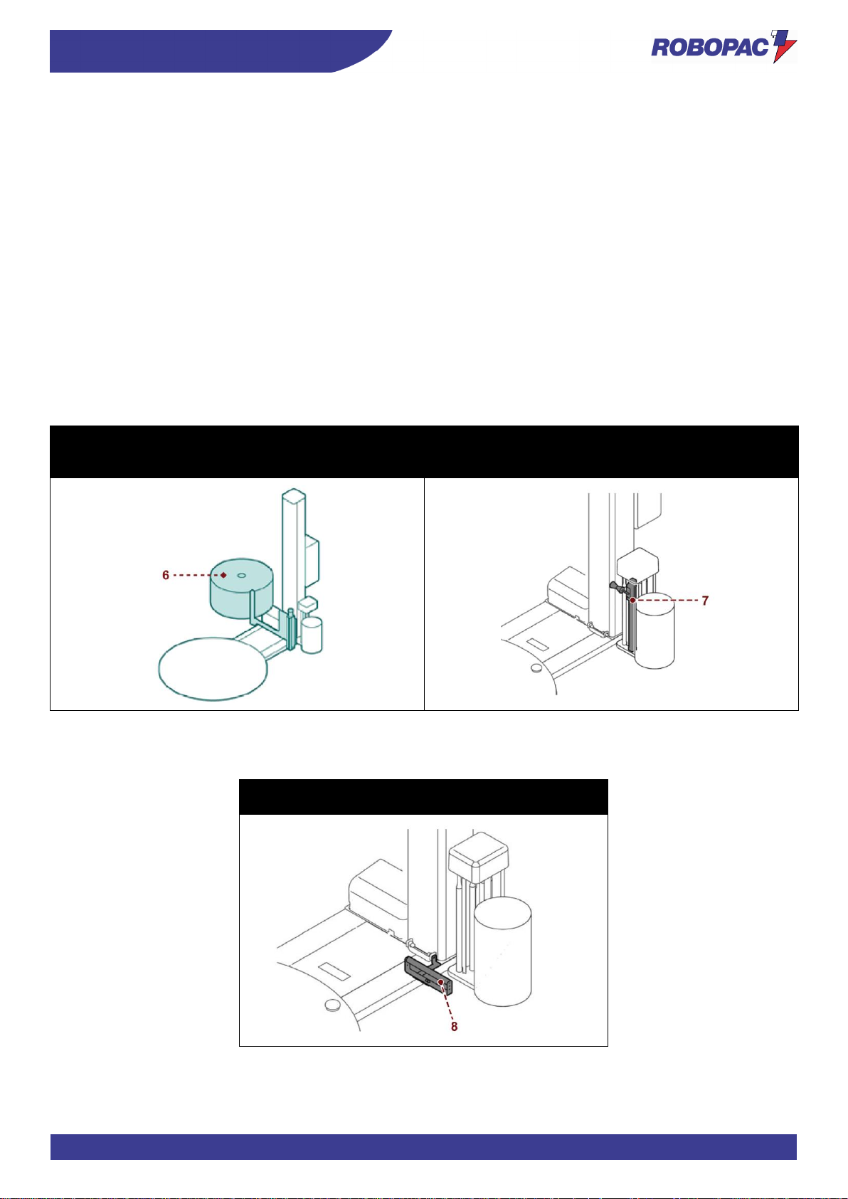
7. Creasing device:
it is used during wrapping to gather the film in one point, providing the package with a reinforcement point.
Rotoplat 308-508-708
Rotoplat 308-508-708
Rotoplat LP 308FR-508PDS-708PVS
Rotoplat TP3 308-508-708
8. Film reinforcement tool:
it is used to create a film reinforcement on the base of the product or on the pallet.
Rotoplat 308-508-708
Rotoplat TP3 308-508-708
Page 38
ENG
TECHNICAL INFORMATION
38
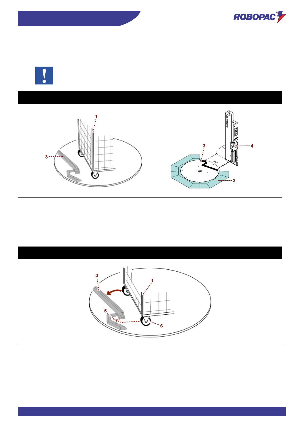
9. Roll-container stop device:
this system is suitable for Roll-container (1) wrapping.
In this case, infeed ramp (2) position is bound to stop device position (3), in fact the recommended ramp type
is the one indicated in the figure (270°).
Important
If the Roll-container stop device (3) is used, set the film stretch (4) to low intensity to avoid load
overturning.
Rotoplat TP3 308-508-708
Rotoplat LP 308-508-708
Roll-container insertion
Insert Roll-container (1) as follows:
A. Insert a fixed wheel (6) inside area (5), as indicated.
B. Rotate Roll-container (1) until bracket stops (3), as indicated.
Rotoplat TP3 308-508-708
Rotoplat LP 308-508-708
Page 39
39
TECHNICAL INFORMATION
ENG
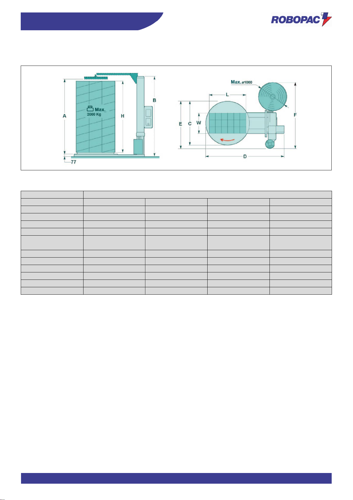
3.7. "ROTOPLAT 308-508-708" TECHNICAL DATA
The illustration and the table include the machine dimensional specifications and technical data.
3.7.1. MACHINE AND PALLET DIMENSIONS
Description
Rotoplat
Standard
Optional
Optional
Optional
Shaft height
A 2350
2550
2950
3250
H
2200
2400
2800
3100
B
2560
2760
3160
3460
Load overall
dimensions
1650
1800
- C 1650
1800
2200
2400
D
2755
2835
3535
3635
E
2313
2313
2446
2546
L
1000
1200
1400
1400
W
1200
1200
1600
1600
Weight (kg)
2000
2000
2000
200
Page 40
ENG
TECHNICAL INFORMATION
40
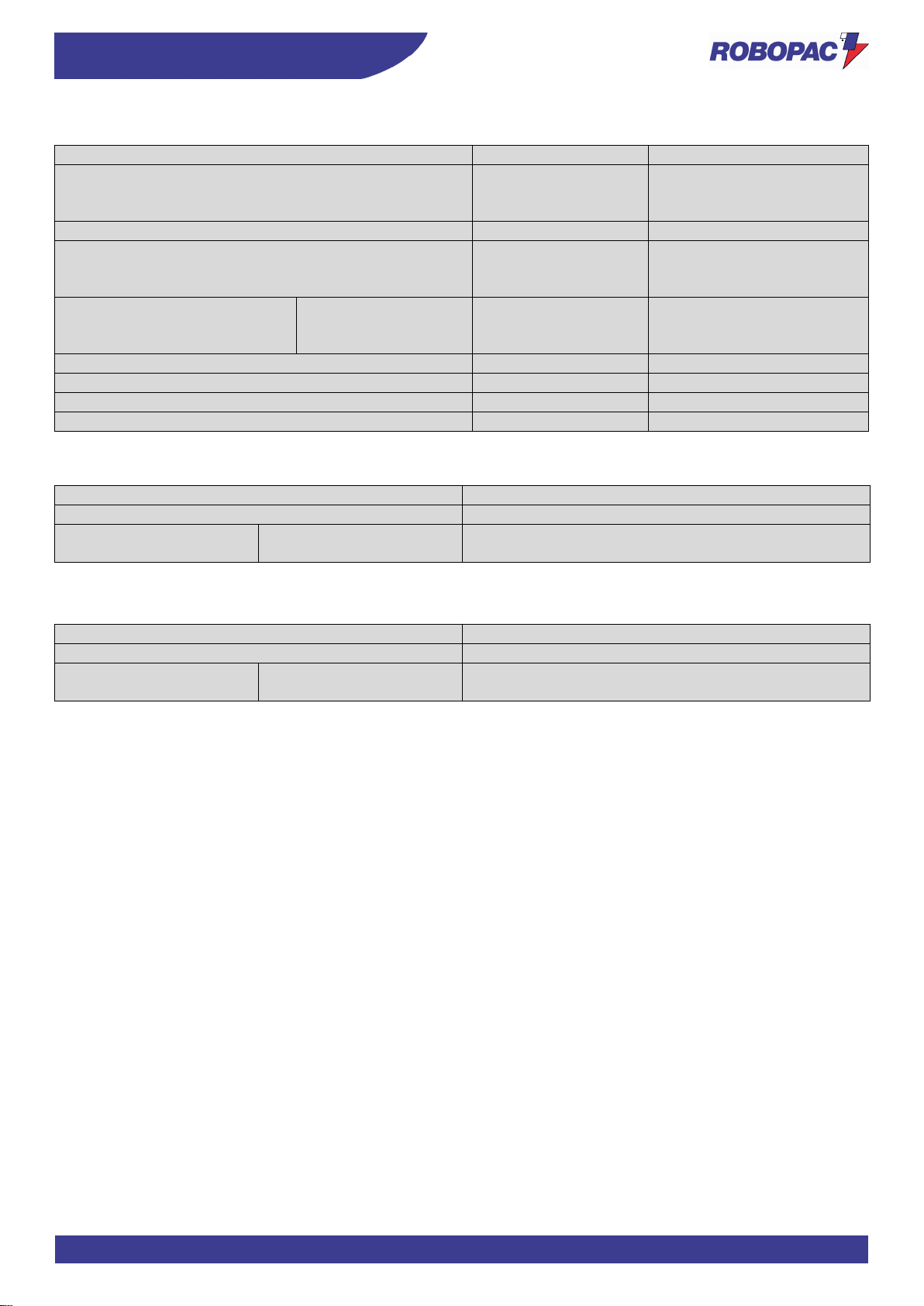
3.7.2. MACHINE TECHNICAL FEATURES
Description
Unit of measurement
EU
Supply voltage
V
220÷240 1Ph
220÷240 3Ph
380÷415 3Ph+N
Power supply frequency
Hz
50/60
Power
installed
kW
1.5 (Rotoplat 108 - 308)
1.9 (Rotoplat 508)
2.4 (Rotoplat 708)
Table
rotation speed
C=1650
C=1800
C=2200-2400
rpm
5-12
5-11
5-8
Carriage upstroke / downstroke speed
m/min.
1.5-5.5
Maximum capacity
kg
2000
Overall weight
kg
395÷455
Ambient operating temperature
°C
0÷40
3.7.3. PRESSER TECHNICAL FEATURES
Description
Value
Working pressure
6 (±1) bar (0.6±0.1 MPa)
Pneumatic cylinder with
rod
H=2200/2400
2800/3100
Air consumption
11 Nl/min
3.7.4. PNEUMATIC CREASING HEAD TECHNICAL FEATURES
Description
Value
Working pressure
6 (±1) bar
Pneumatic cylinder
without rod
H=450
Air consumption
2 Nl/min
Page 41
41
TECHNICAL INFORMATION
ENG
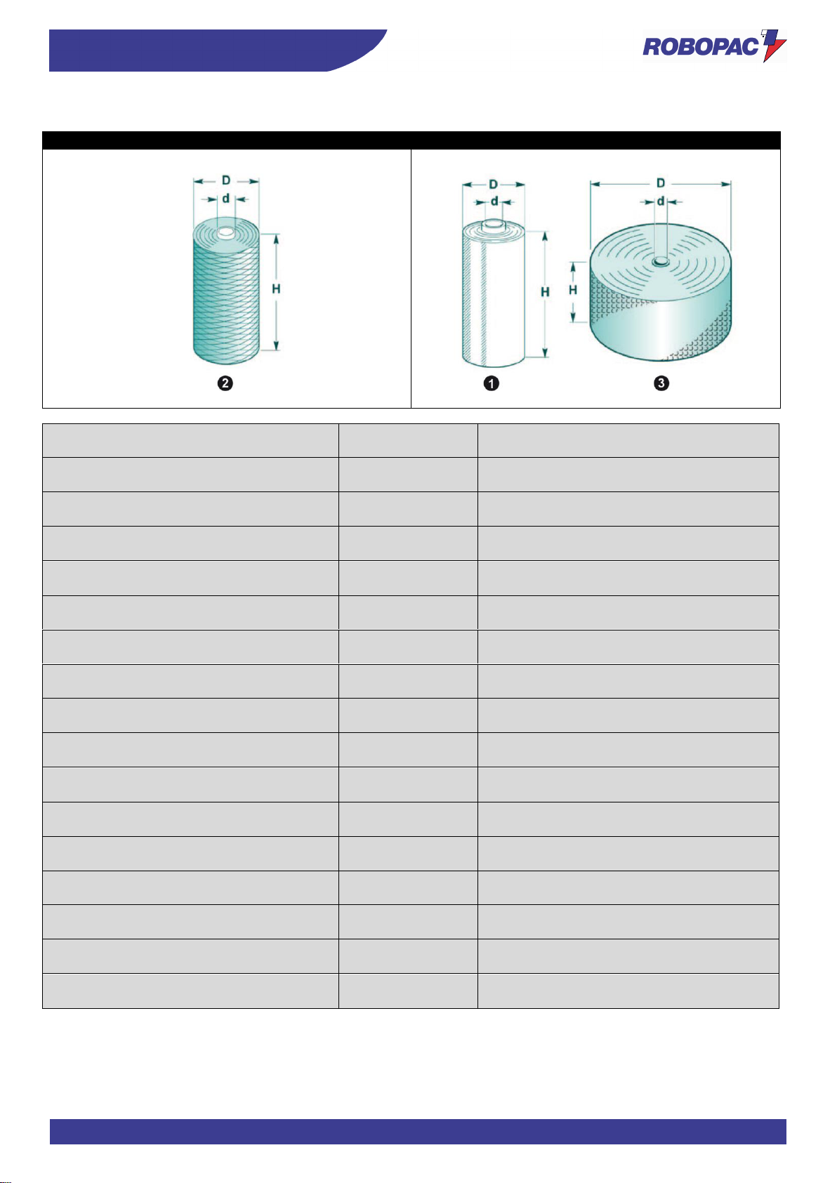
3.7.5. SPOOL FEATURES
Rotoplat 308
Rotoplat 308-508-708
Description
Unit of
measurement
Value
Film spool dimensions (1)
Maximum outer diameter (D)
mm 300 Spool height (H)
mm 500 Film thickness
μm 17÷35
Internal diameter (d)
mm 76
Max. weight
kg 20
Mesh spool dimensions (2)
Maximum outer diameter (D)
mm 300 Spool height (H)
mm 500 Internal diameter (d)
mm 76 Max. weight
kg 20 “Bubble wrap” spool dimensions (3)
Maximum outer diameter (D)
mm 1000
Spool height (H)
mm 500 Internal diameter (d)
mm 76 Max. weight
kg 12
Page 42
ENG
TECHNICAL INFORMATION
42
3.8. "ROTOPLAT LP 308 - 508 - 708" TECHNICAL DATA
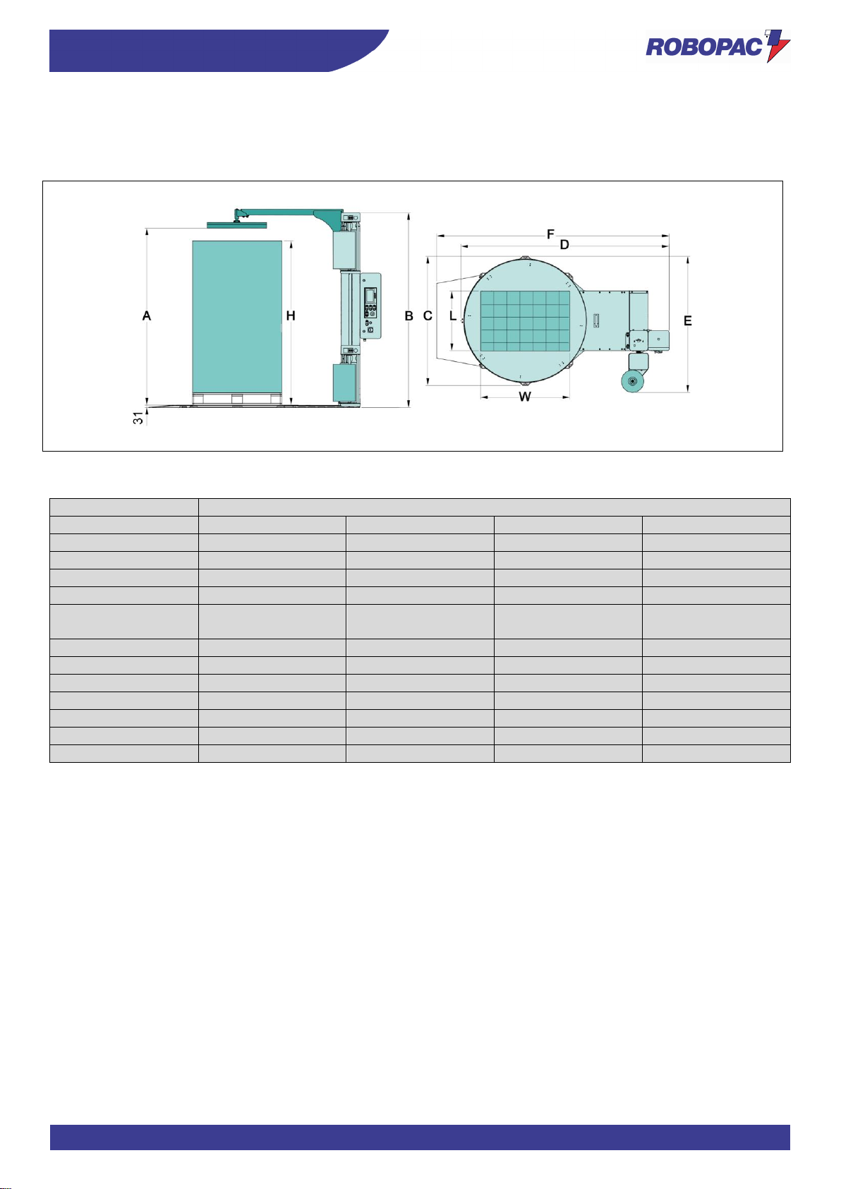
The illustration and the table include the machine dimensional specifications and technical data.
308 – 508 –708
3.8.1. MACHINE AND PALLET DIMENSIONS
Description
Rotoplat LP
Standard
Optional
Optional
Optional
Shaft height
A 2350
2550
2950
3250
H
2200
2400
2800
3100
B
2532
2732
3132
3432
Load overall
dimensions
1650
- - C 1732
- - - D 2802
- - - E 1826
- - - L 1000
- - - W 1200
- - - F
3126
Weight (kg)
1200
- - -
Page 43
43
TECHNICAL INFORMATION
ENG
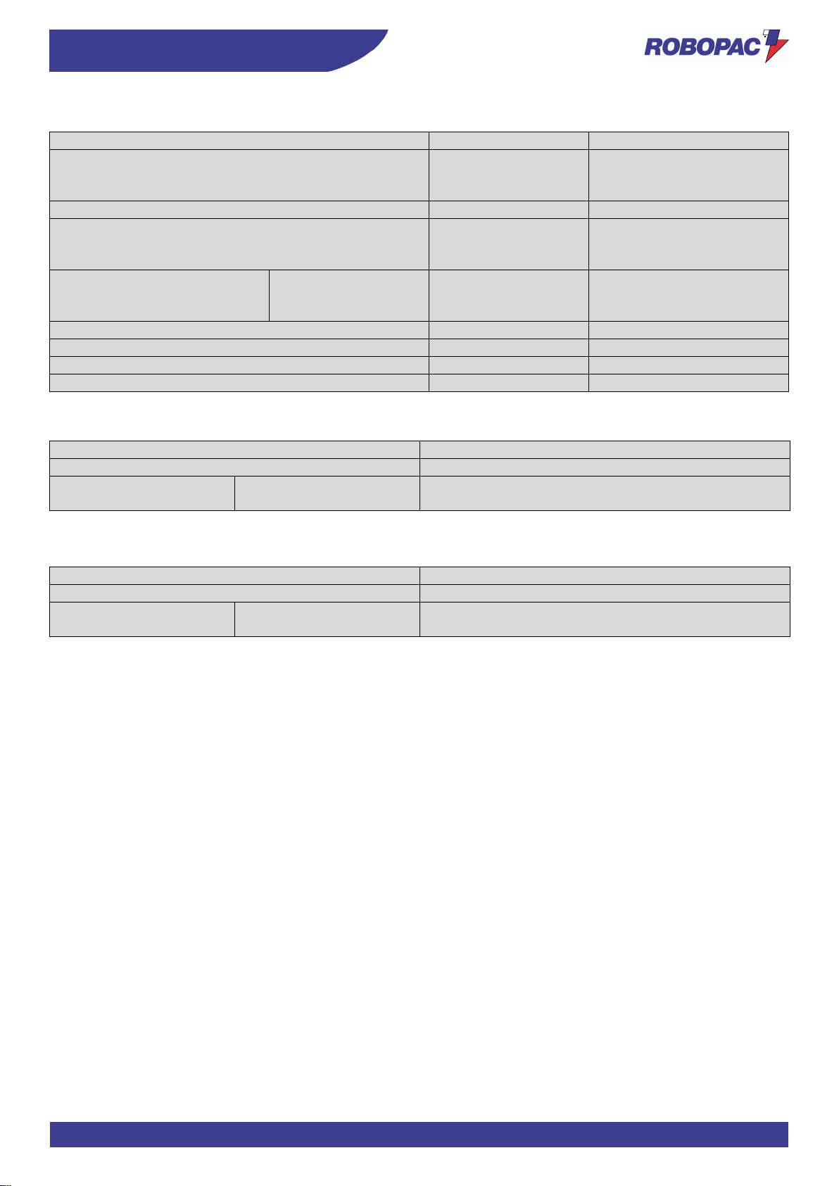
3.8.2. MACHINE TECHNICAL FEATURES
Description
Unit of measurement
EU
Supply voltage
V
220÷240 1Ph
220÷240 3Ph
380÷415 3Ph+N
Power supply frequency
Hz
50/60
Power
installed
kW
1.5 (Rotoplat 308)
1.9 (Rotoplat 508)
2.4 (Rotoplat 708)
Table
rotation speed
C=1650
C=1800
C=2200-2400
rpm
5-12
5-11
5-8
Carriage upstroke / downstroke speed
m/min.
1.5-5.5
Maximum capacity
kg
1200
Overall weight
kg
470÷580
Ambient operating temperature
°C
0÷40
3.8.3. PRESSER TECHNICAL FEATURES
Description
Value
Working pressure
6 (±1) bar (0.6±0.1 MPa)
Pneumatic cylinder with
rod
H=2200/2400
2800/3100
Air consumption
11 Nl/min
3.8.4. PNEUMATIC CREASING HEAD TECHNICAL FEATURES
Description
Value
Working pressure
6 (±1) bar
Pneumatic cylinder
without rod
H=450
Air consumption
2 Nl/min
Page 44
ENG
TECHNICAL INFORMATION
44
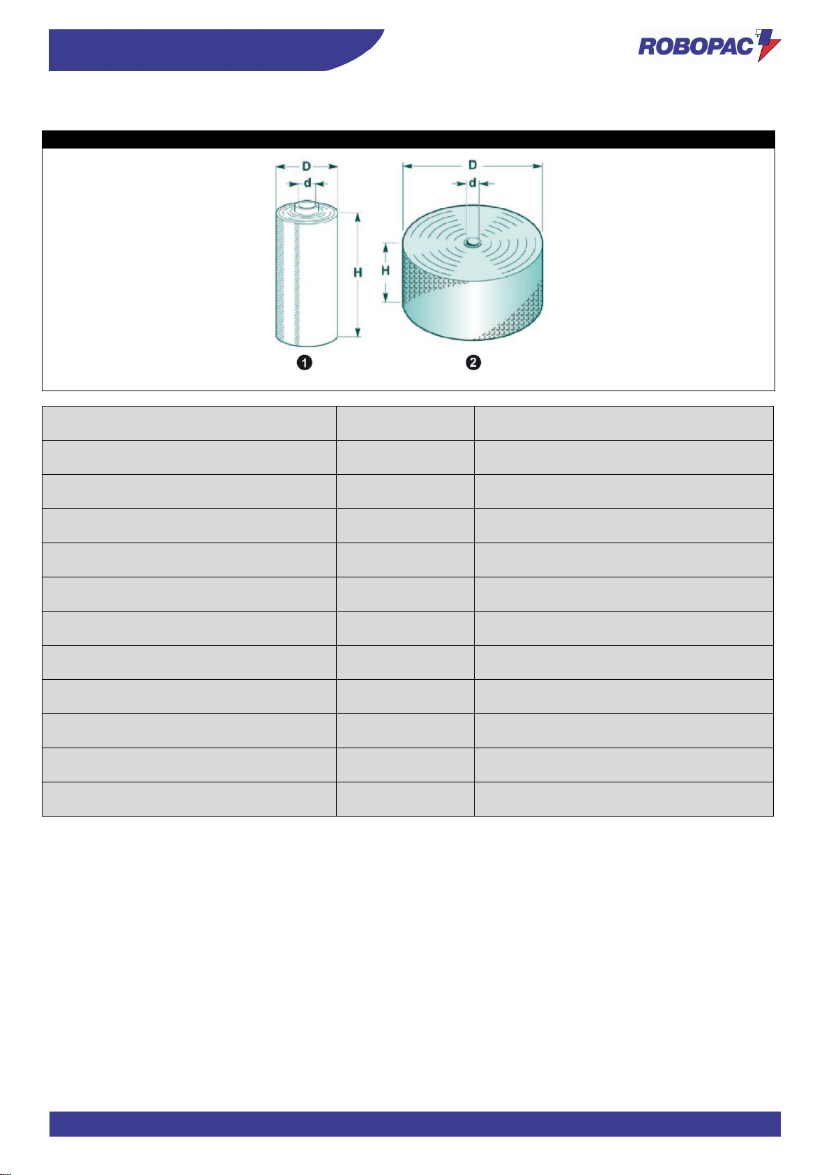
3.8.5. SPOOL FEATURES
Rotoplat LP 308-508-708
Description
Unit of
measurement
Value
Film spool dimensions (1)
Maximum outer diameter (D)
mm 300 Spool height (H)
mm 500 Film thickness
μm 17÷35
Internal diameter (d)
mm 76 Max. weight
kg 20 “Bubble wrap” spool dimensions (2)
Maximum outer diameter (D)
mm 1000
Spool height (H)
mm 500 Internal diameter (d)
mm 76 Max. weight
kg 12
Page 45
45
TECHNICAL INFORMATION
ENG
3.9. “ROTOPLAT TP3 308-508-708" TECHNICAL DATA
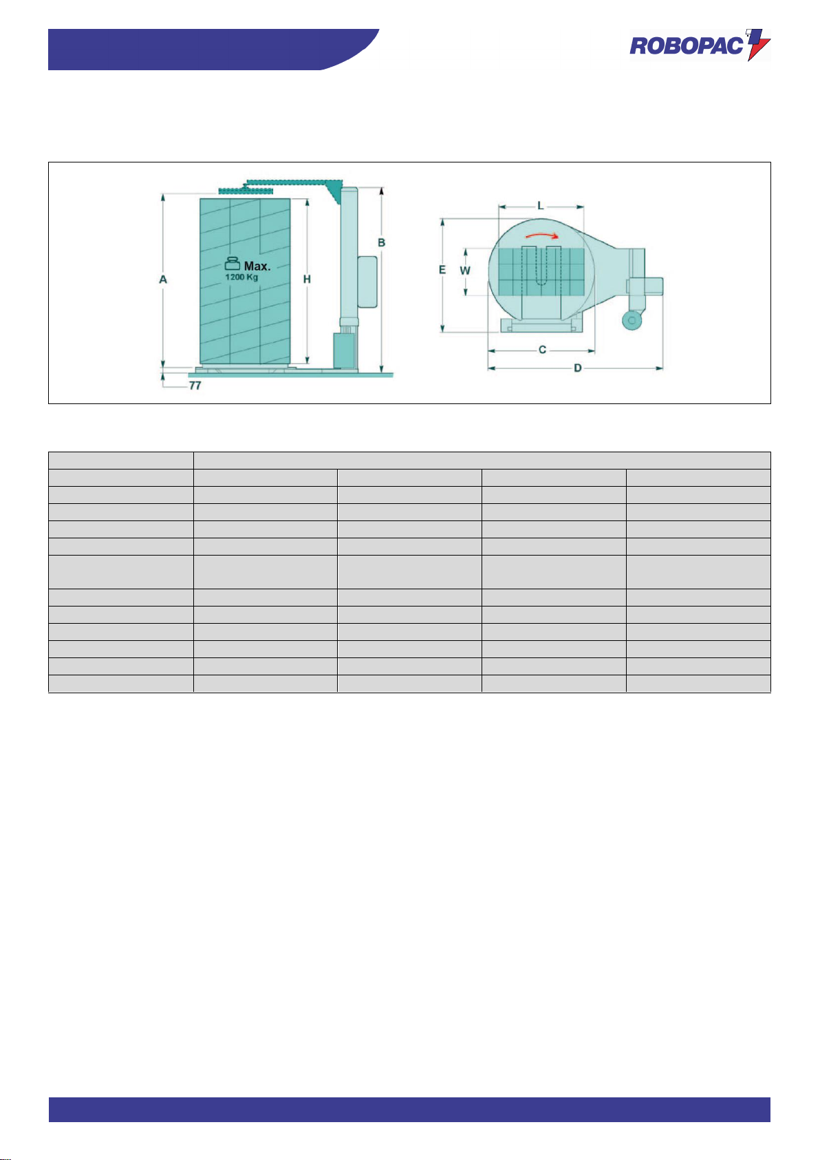
The illustration and the table include the machine dimensional specifications and technical data.
3.9.1. MACHINE AND PALLET DIMENSIONS
Description
Rotoplat TP3
Standard
Optional
Optional
Optional
Shaft height
A 2350
2550
2950
3250
H
2200
2400
2800
3100
B
2560
2760
3160
3460
Load overall
dimensions
1650
1800
- C 1650
1800
2200
2400
D
2755
2835
3535
3635
E
2313
2313
2446
2546
L
1000
1200
1400
1400
W
1200
1200
1600
1600
Weight (kg)
2000
2000
2000
200
Page 46
ENG
TECHNICAL INFORMATION
46
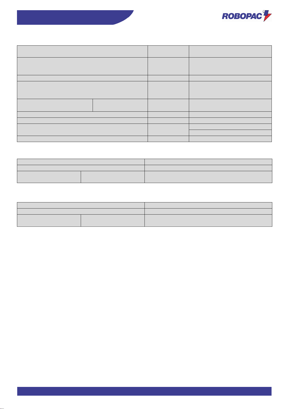
3.9.2. MACHINE TECHNICAL FEATURES
Description
Unit of
measurement
EU
Supply voltage
V
220-240 1Ph
220-240 3Ph
380-415 3Ph+N
Electrical current frequency
Hz
50/60
Power
installed
kW
1.5 (Rotoplat 108 - 308)
1.9 (Rotoplat 508)
2.4 (Rotoplat 708)
Table rotation
speed
C=1650
C=1800
rpm
5-12
5-11
Carriage upstroke / downstroke speed
m/min.
1.5-5.5
Maximum capacity
kg
1500
Overall weight
kg
525÷530 (Rotoplat TP3 108-308)
550÷560 (Rotoplat TP3 508-708)
Ambient operating temperature
°C
0÷40
3.9.3. PRESSER TECHNICAL FEATURES
Description
Value
Working pressure
6 (±1) bar (0.6±0.1 MPa)
Pneumatic cylinder with
rod
H=2200/2400
2800/3100
Air consumption
11 Nl/min
3.9.4. PNEUMATIC CREASING HEAD TECHNICAL FEATURES
Description
Value
Working pressure
6 (±1) bar
Pneumatic cylinder
without rod
H=450
Air consumption
2 Nl/min
Page 47
47
TECHNICAL INFORMATION
ENG
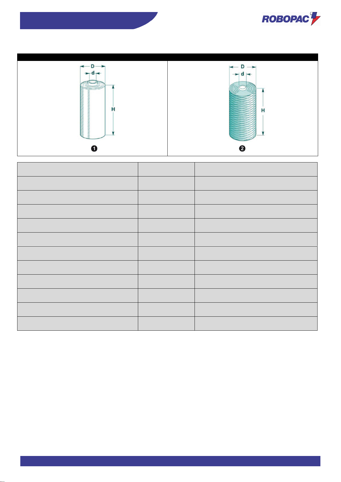
3.9.5. SPOOL FEATURES
Rotoplat TP3 308-508-708
Rotoplat TP3 308
Description
Unit of
measurement
Value
Film spool dimensions (1)
Maximum outer diameter (D)
mm 300 Spool height (H)
mm 500 Film thickness
μm 17÷35
Internal diameter (d)
mm 76 Max. weight
kg 20 Mesh spool dimensions (2)
Maximum outer diameter (D)
mm 300 Spool height (H)
mm 500 Internal diameter (d)
mm 76 Max. weight
kg 20
Page 48
ENG
TECHNICAL INFORMATION
48
3.10. NOISE LEVEL
The values relating to airborne noise have been detected in compliance with standards:
-
ISO 4871
-
ISO 11201
Description
A-weighted emission sound pressure measured level at
the operator’s position (LpA)
Operation in working conditions.
69.3 dB (A)
Caution - warning
Prolonged exposure above 80 dB (A) can be harmful.
The use of appropriate protection systems is recommended (earmuffs, ear plugs, etc.).
3.11. INSTALLATION ENVIRONMENT CHARACTERISTICS
The place where the machine is to be installed must be carefully selected taking into account the environment
conditions in order to have correct and risk-free operating conditions.
Therefore we suggest to take into account the following prerequisites:
- An appropriate ambient temperature (see “Technical data”).
- A perimeter area that must be left around the immediate working area, also for safety reasons (see “Perimeter
areas”).
- A flat surface, steady and without vibrations with adequate load bearing capacity, considering also the weight of
palletised loads.
- The area must feature suitable sockets for compressed air and power distribution.
Danger - warning
Using this machine in explosive environments or when exposed to atmospheric agents is strictly
forbidden.
Page 49
49
INFORMATION ON HANDLING AND INSTALLATION
ENG
4. INFORMATION ON HANDLING AND INSTALLATION
4.1. RECOMMENDATIONS FOR HANDLING AND LOADING
- Before performing any operation, the authorised operator must make sure to have understood the
“Instructions for use”.
- Carefully read the “Instructions for use” specified in the manual and those applied directly to the machine
and/or the package.
- Provide suitable safety conditions in compliance with the regulations on workplace safety to prevent and
minimise the risks.
- Pay attention to the safety warnings, do not misuse the machine and assess the possible residual risks.
4.2. PACKING AND UNPACKING
The packing is realised, keeping the overall dimensions limited, also in consideration of the transport chosen.
To facilitate transport, shipping can be performed with some components disassembled and appropriately protected
and packaged.
Some parts, especially electrical equipment, are protected with anti-moisture nylon covers.
The packages bear all necessary information for loading and unloading.
When unpacking, check the integrity and exact quantity of the components.
Packaging material should be appropriately disposed of according to the laws in force.
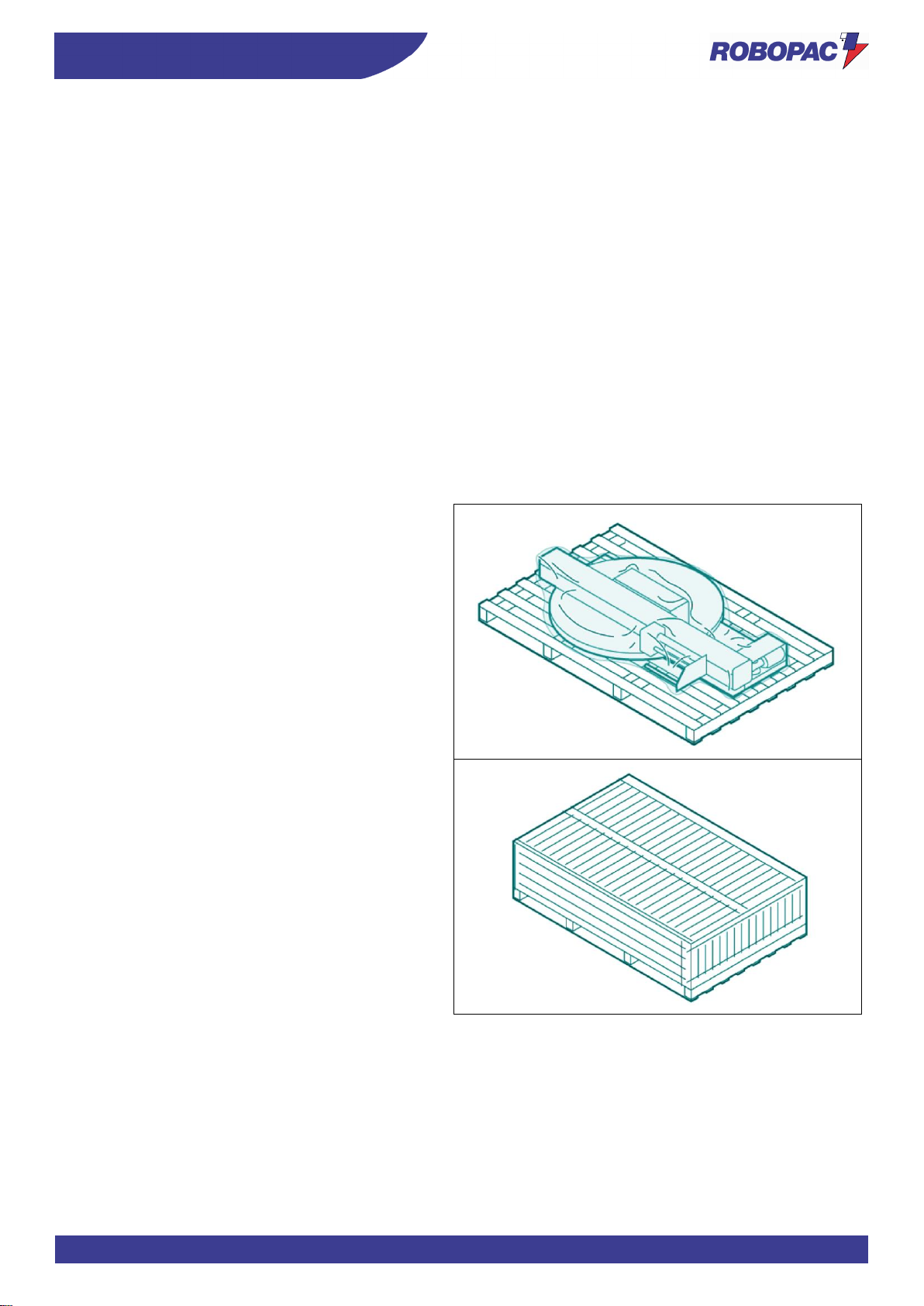
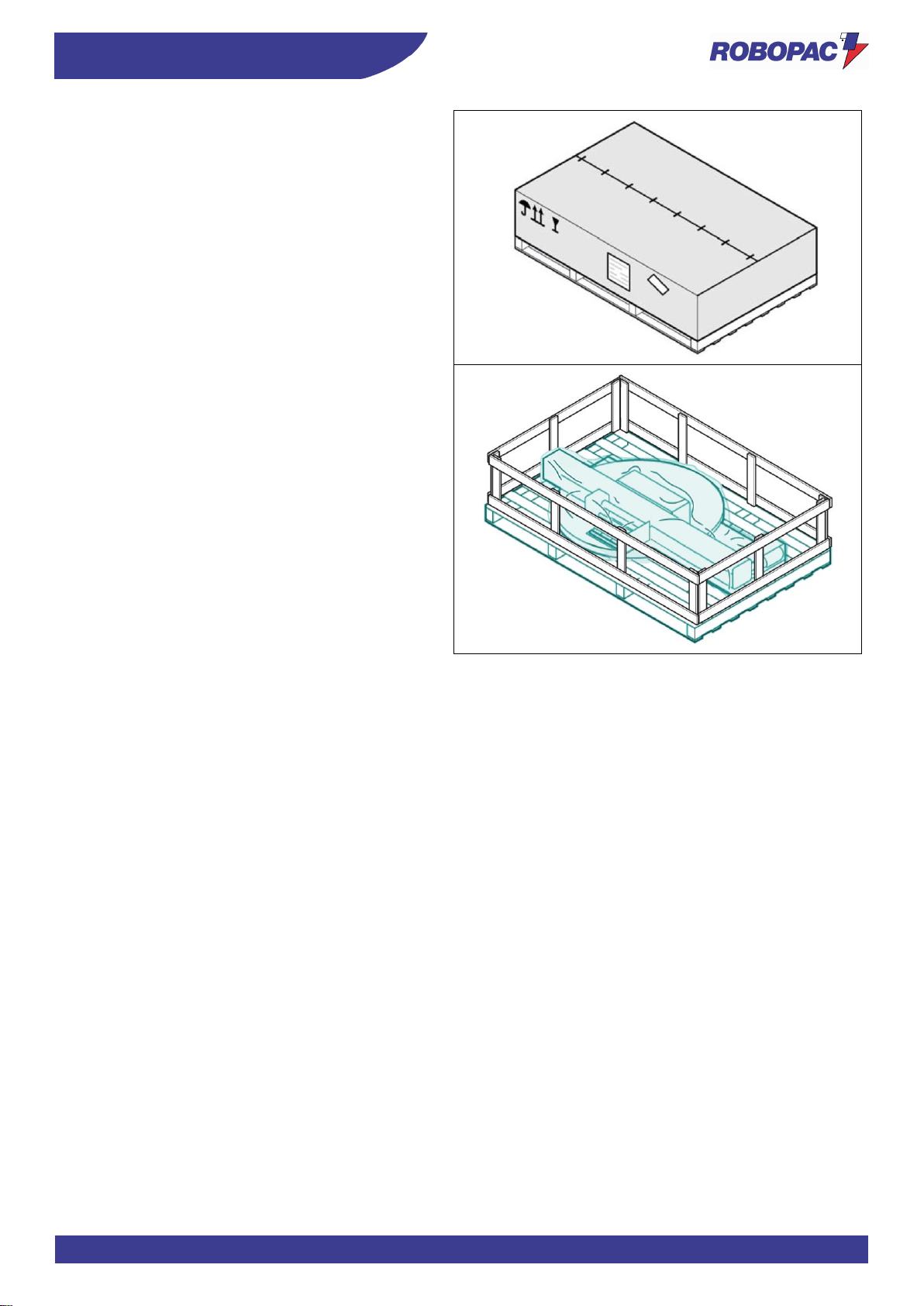
The illustrations show the common types of packaging used.
Package on pallet with nylon protection
Package in crate
Page 50
ENG
INFORMATION ON HANDLING AND INSTALLATION
50
Package with cardboard box
Package in cage
Page 51
51
INFORMATION ON HANDLING AND INSTALLATION
ENG
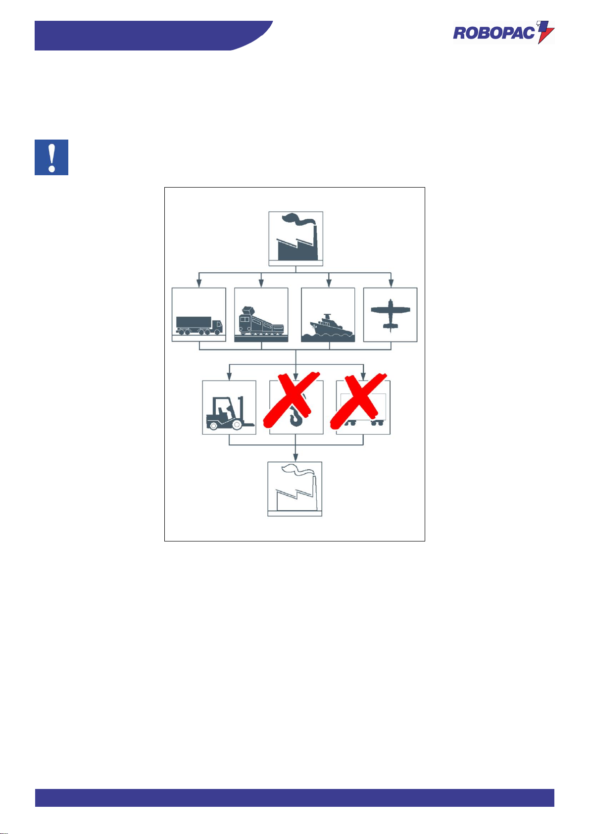
4.3. TRANSPORT AND HANDLING
Transport, also according to the destination, can be performed with different vehicles.
The diagram represents the most used solutions.
During transport, in order to avoid sudden movements, adequately anchor the machine to the vehicle.
Important
For further transportations, recreate the initial packaging conditions for transport and handling.
Page 52
ENG
INFORMATION ON HANDLING AND INSTALLATION
52
4.4. HANDLING AND LIFTING
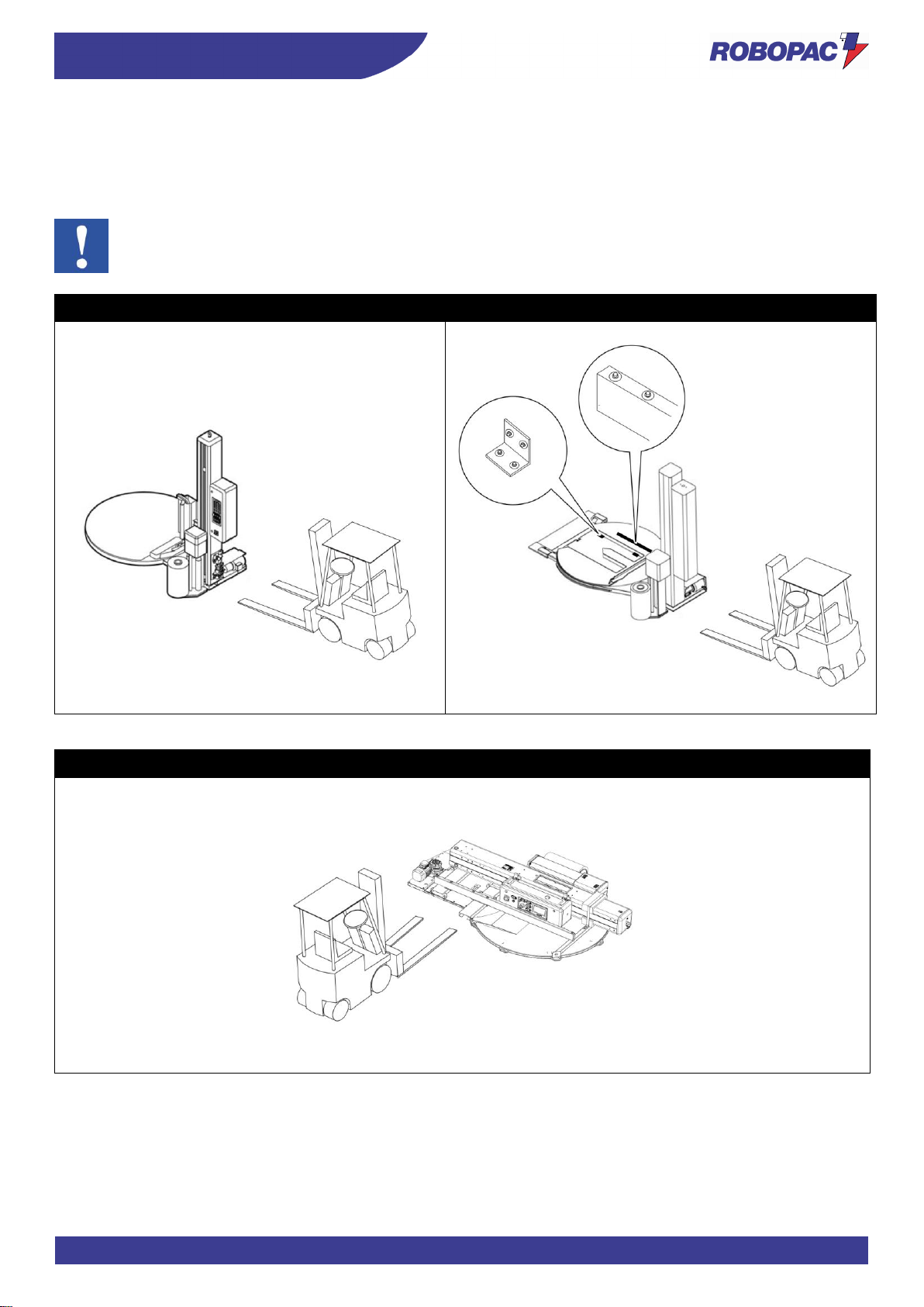
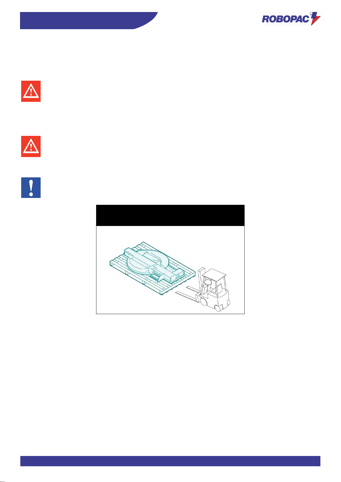
The machine can be moved with a forklift truck with suitable load capacity by inserting the forks in the points indicated
directly on the machine.
Transport and lifting means must be operated by personnel authorised and qualified for the use of such means.
Important
To handle the TP3 version machine, the brackets must be installed as indicated in the figure.
Rotoplat 308-508-708
Rotoplat TP3 308-508-708
Rotoplat LP 308-508-708
Page 53
53
INFORMATION ON HANDLING AND INSTALLATION
ENG
4.5. INSTALLATION OF THE MACHINE
The machine must be installed in an area which fulfils the requirements indicated in paragraph “Installation
environment characteristics”.
If necessary, identify the exact position by plotting the coordinates for correct positioning.
Danger - warning
Authorised technical service personnel must perform installation and assembly operations.
Proceed as follows:
1. Insert the forklift truck forks in the specially designed spaces provided in the base.
2. Lift the machine from the pallet (if any).
Danger - warning
To perform the operation in safety conditions, insert some wooden blocks under the forks of the forklift
truck and place everything on the floor.
3. Place the machine in the area assigned for assembly.
Important
The resting surface must be smooth and well levelled.
Rotoplat 308-508-708
Rotoplat LP 308-508-708
Rotoplat TP3 308-508-708
Page 54
ENG
INFORMATION ON HANDLING AND INSTALLATION
54
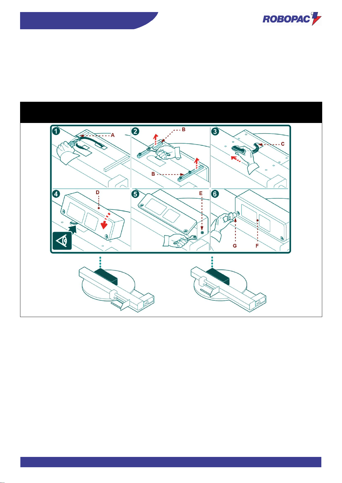
4.5.1. ELECTRIC BOX ASSEMBLY
1. Cut the tie (A) which gathers the electric cables.
2. Remove the mounting brackets (B).
3. Route the electric cables (C) inside the slide shaft.
4. Lift the electric box (D).
5. Fasten the electric box to the slide shaft with the screws (E).
6. Close the cover (F) of the electric box (D) with the suitable key (G).
Rotoplat 308-508-708
Rotoplat LP 308-508-708
Rotoplat TP3 308-508-708
Page 55
55
INFORMATION ON HANDLING AND INSTALLATION
ENG
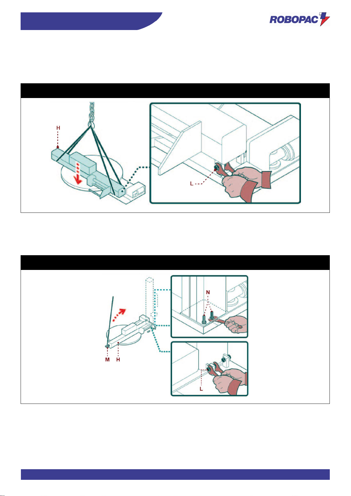
4.5.2. SLIDE SHAFT ASSEMBLY
1. In certain configurations it is necessary to lift and position the slide shaft (H) above the rotary table, in
correspondence with the hinge.
2. Insert the screws (L) into the hinge without tightening them.
Rotoplat 308-508-708
Rotoplat TP3 308-508-708
3. Connect the lifting device hook in the bracket (M) of the slide shaft and tension.
4. Lift the slide shaft (H).
5. Fasten the slide shaft to the machine body with the screws (N).
6. Tighten the screws of the hinge (L).
Rotoplat 308-508-708
Rotoplat TP3 308-508-708
Page 56
ENG
INFORMATION ON HANDLING AND INSTALLATION
56
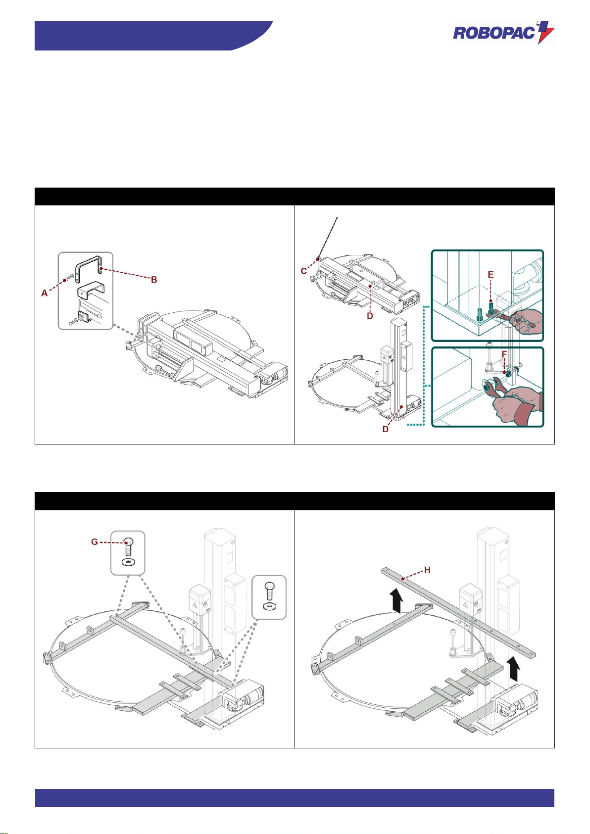
4.5.3. SLIDE SHAFT ASSEMBLY
1. Loosen the screws (A).
2. Lift the latch of the slide shaft (B).
3. Connect the hook of the lifting device to the bracket (C) of the slide shaft and tension (Only for slide shaft with
a height of 2200-2400 mm).
4. Lift the slide shaft (D).
5. Fasten the slide shaft to the machine body with the screws (E).
6. Tighten the screws of the hinge (F).
Rotoplat LP 308-508-708
7. Loosen the screws (G).
8. Remove the bracket (H).
Rotoplat LP 308-508-708
Page 57
57
INFORMATION ON HANDLING AND INSTALLATION
ENG
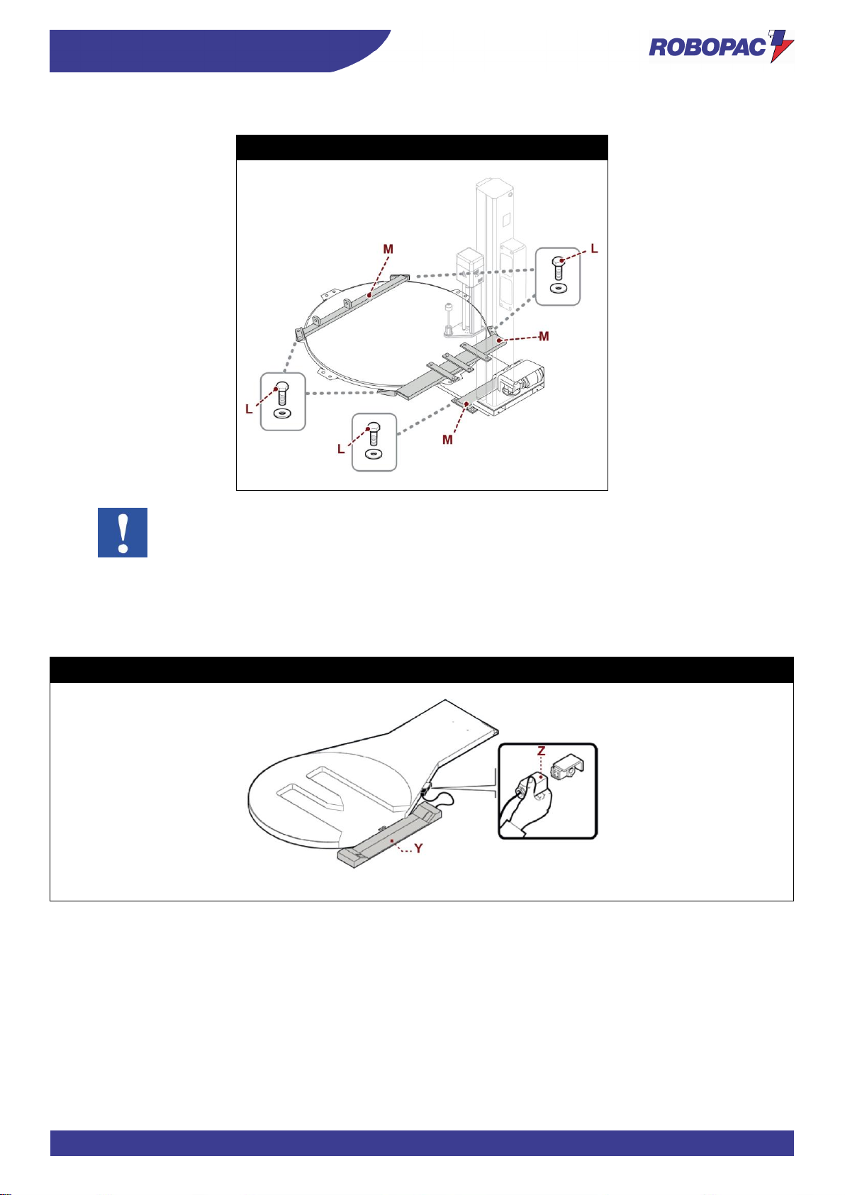
9. Loosen the screws (L) and remove the brackets (M).
Rotoplat LP 308-508-708
Important
Store the components for lifting / handling.
4.5.4. LOADING/UNLOADING RAMP ASSEMBLY
Assemble the pallet loading/unloading ramp (Y) and connect the power connector (Z).
Rotoplat TP3 308-508-708
Page 58
ENG
INFORMATION ON HANDLING AND INSTALLATION
58
4.5.4.1. LOADING DIRECTION MODIFICATION
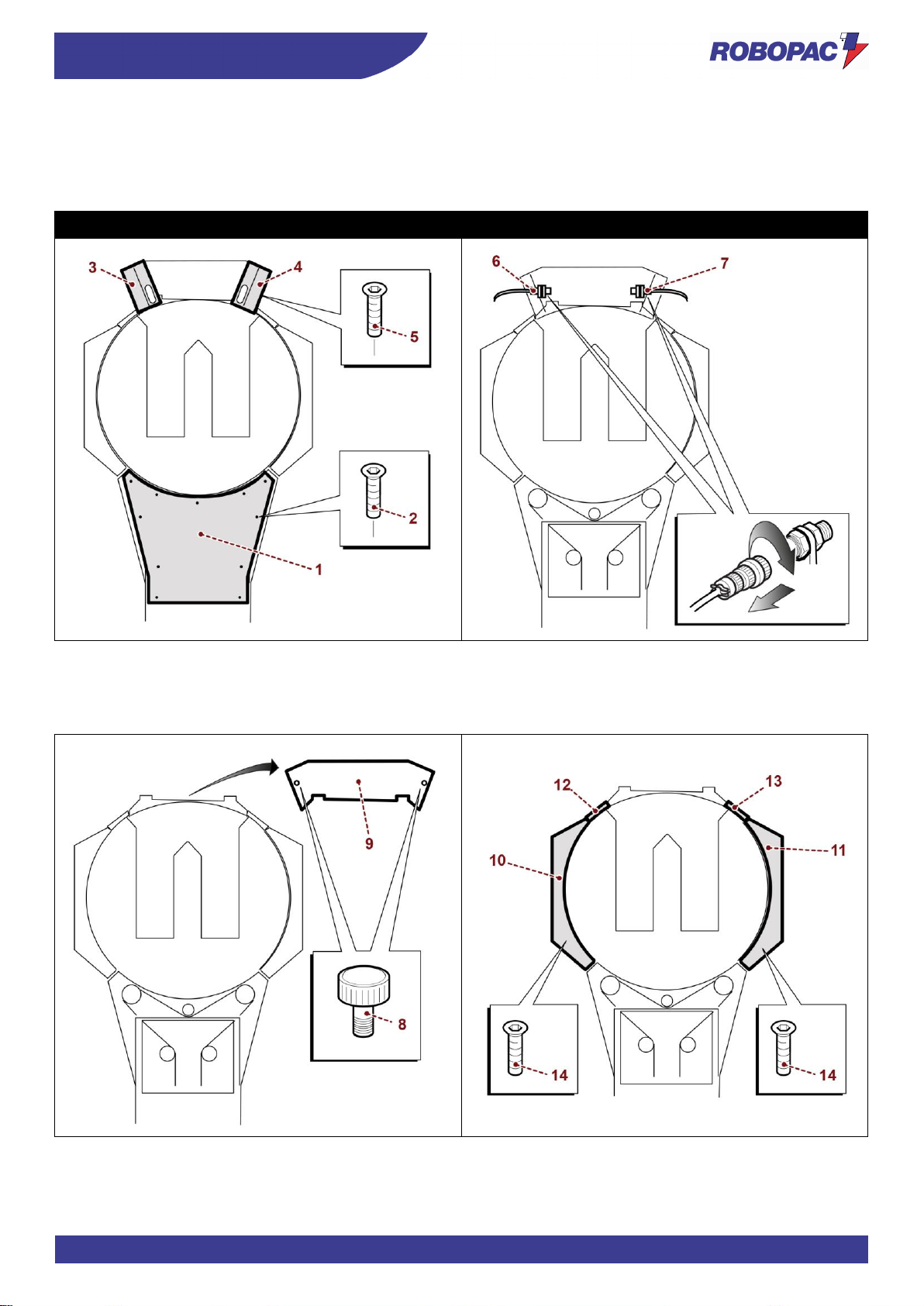
A. Remove the chain cover base (1) by loosening the fastening screws (2).
Remove the guards (3) and (4) that cover the loading ramp photocell, by loosening the fastening screws (5).
B. Disconnect the cable of photocell (6) and (7), for the emitter and the receiver.
Rotoplat TP3 308-508-708
C. Insert the supporting knobs (8) and move the upstroke ramp (9).
D. Remove one of the two upper LH (10) or RH (11) guards and one of the two upper connection guards (12) or
(13), by loosening the fastening screws (14).
Page 59
59
INFORMATION ON HANDLING AND INSTALLATION
ENG
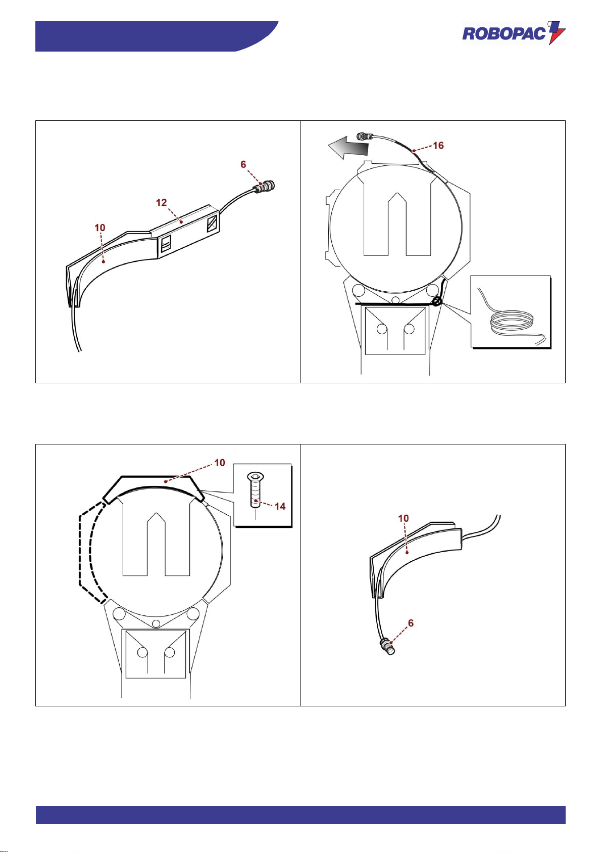
E. Remove the connector cable (6) from the chosen side (in this case, LH 10) and from the connection guards
(12).
F. Slide the photocell receiver connector cable (16) out from the opposite side of the ramp position.
G. Remove the guard (10) from the initial position and reposition it on the front side, fastening it with the screws
(14).
H. Reposition the photocell receiver connector cable (16) in the guard (10) and in the connection guard (12).
Page 60
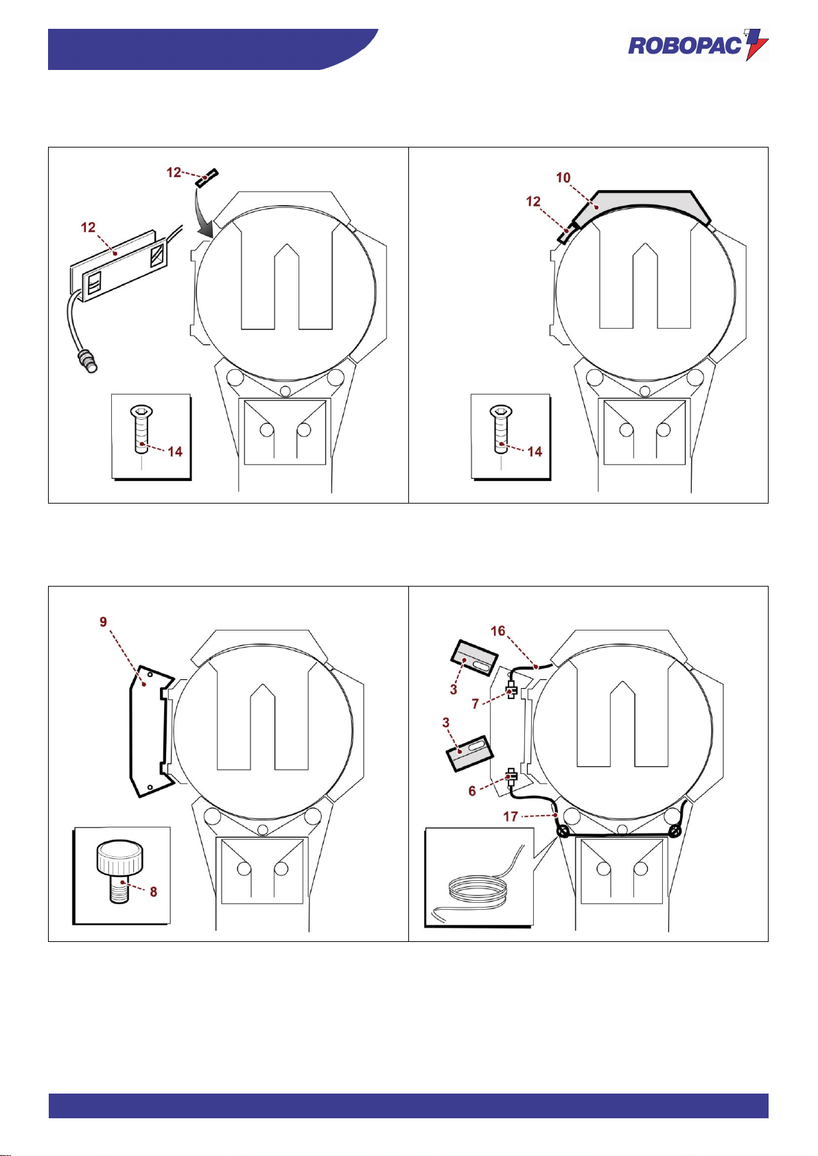
ENG
INFORMATION ON HANDLING AND INSTALLATION
60
I. Fasten the connection guard (12) with the screws (14) and insert the cable inside it.
J. Refit the upper guard (10) and the upper connection guard (12) with the fastening screws (14).
K. Position the upstroke ramp (9) on the side and screw the supporting knobs (8).
L. Recover the cable in excess (16-17) using a tie, connect the connector (6-7) to the photocell receiver and
position the photocell guard (3).
Page 61
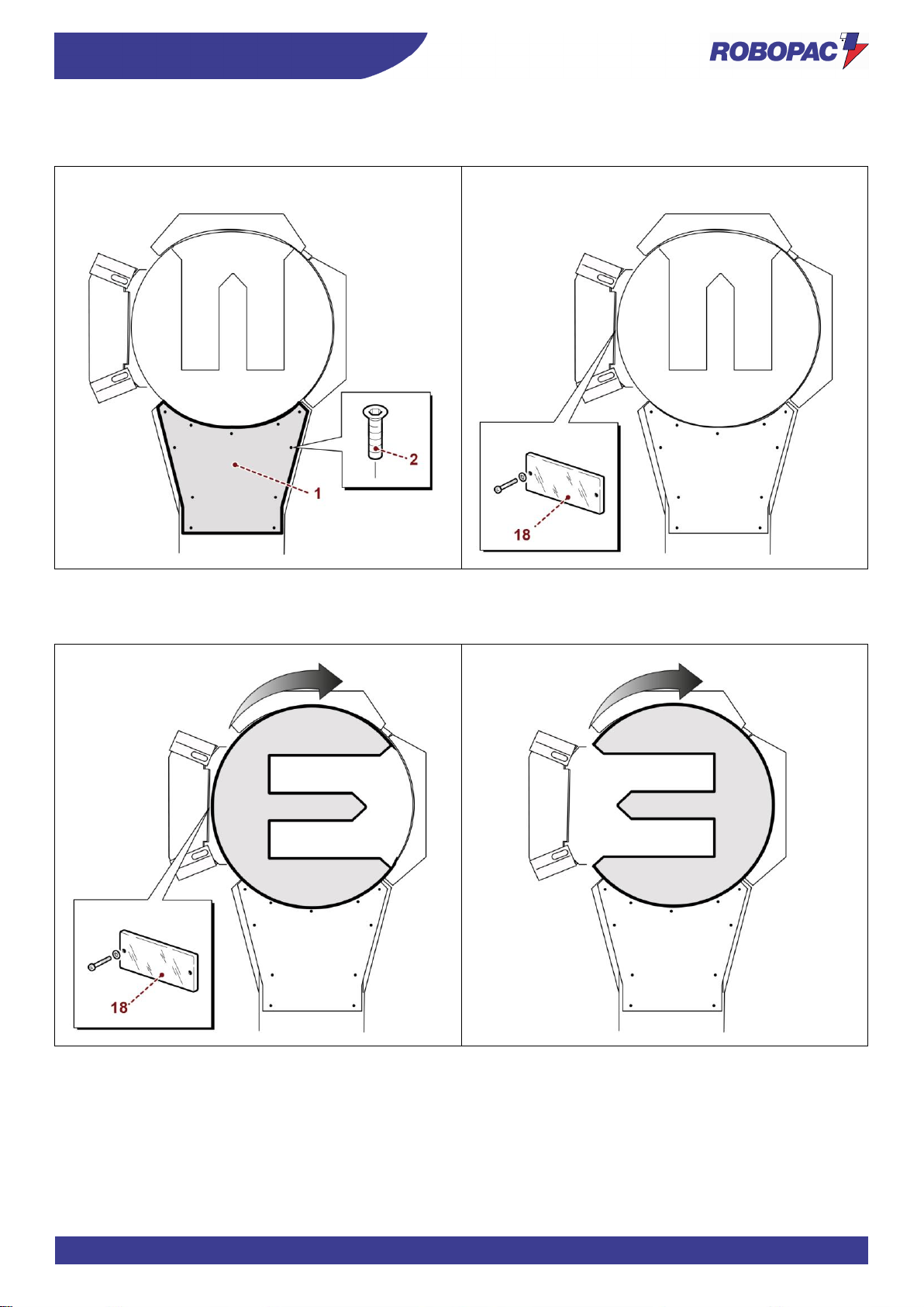
61
INFORMATION ON HANDLING AND INSTALLATION
ENG
M. Refit the guard (1) that covers the base.
N. Unscrew the reflector (18).
O. Turn the plate clockwise until the reflector (18) is positioned on the opposite side of the loading area.
P. Press the “Home position” button to turn the plate clockwise and position it in the loading point.
Page 62
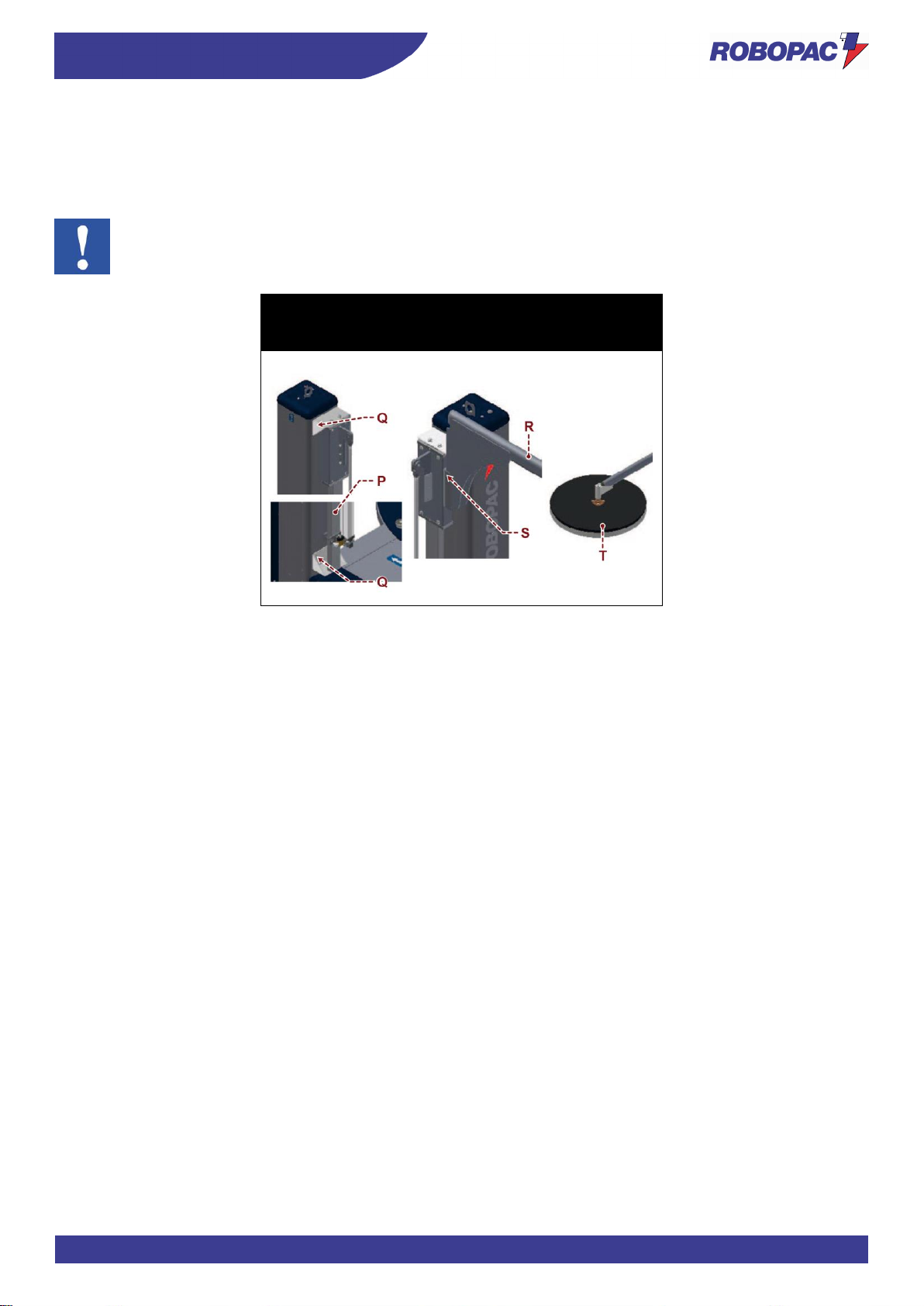
ENG
INFORMATION ON HANDLING AND INSTALLATION
62
4.5.5. PNEUMATIC PRESSER ASSEMBLY (OPTIONAL)
1. Fasten the guide (P) to the slide shaft with the suitable screws (Q).
2. Fit the arm (R) on the guide and fasten it with the screws (S).
3. Fit the presser plate (T) on the arm.
Important
The pneumatic connections have already been performed by the Manufacturer if the presser is delivered
with the machine.
Rotoplat 308-508-708
Rotoplat LP 308-508-708
Rotoplat TP3 108-308-508-708
Page 63
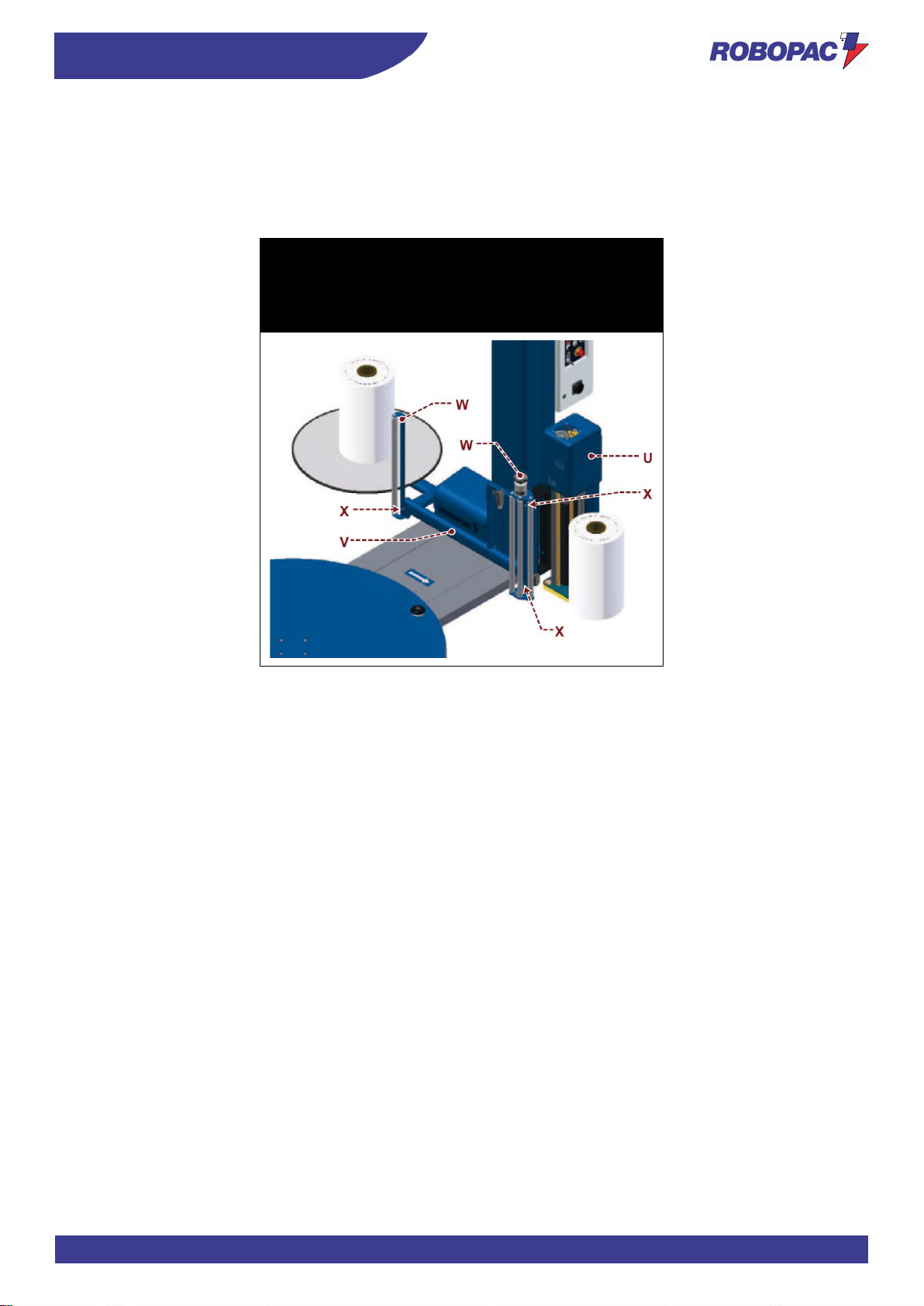
63
INFORMATION ON HANDLING AND INSTALLATION
ENG
4.5.6. “BUBBLE WRAP” KIT ASSEMBLY (OPTIONAL)
1. Remove the spool carriage (U).
2. Fit the frame (V) on the slide shaft.
3. Fit the rollers (W) on the frame (V) with the suitable screws (X).
4. Fit the spool carriage on the frame (V).
Rotoplat 308-508-708 “PLURIBALL”
Rotoplat LP 308FR-508PDS-708PVS “PLURIBALL”
Rotoplat TP3 308-508-708 “PLURIBALL”
Page 64
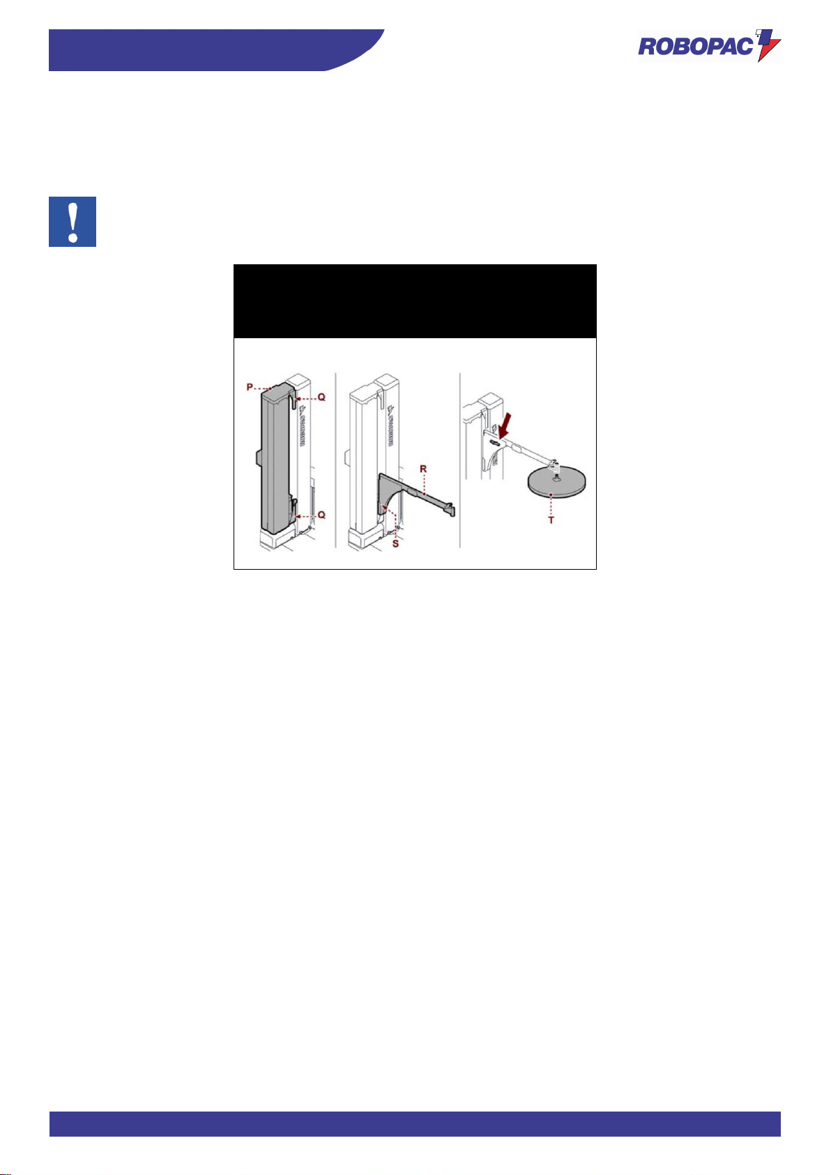
ENG
INFORMATION ON HANDLING AND INSTALLATION
64
4.5.7. MECHANICAL PRESSER ASSEMBLY (OPTIONAL)
1. Fasten the guide (P) to the slide shaft with the suitable screws (Q).
2. Fit the arm (R) on the guide and fasten it with the screws (S).
3. Fit the presser plate (T) on the arm.
Important
The connections have already been performed by the Manufacturer if the presser is delivered with the
machine.
Rotoplat 308-508-708
Rotoplat LP 308-508-708
Rotoplat TP3 308-508-708
Page 65
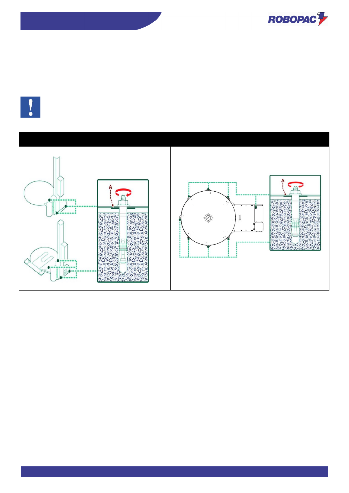
65
INFORMATION ON HANDLING AND INSTALLATION
ENG
4.6. MACHINE FIXING
Once the units have been assembled and levels, squaring, parallelism and orthogonality have been checked, it is
necessary to fix the machine body to the floor.
Depending on the floor type, it may be necessary, before laying the machine, to lay foundations in correspondence of
the various supporting legs.
Laying the foundations and fixing the machine is essential to ensuring the machine stability and functionality.
Important
Should it be necessary, insert metal pates (A) between the screws and the floor.
Rotoplat 308-508-708
Rotoplat LP 308-508-708
Rotoplat TP3 308-508-708
Page 66
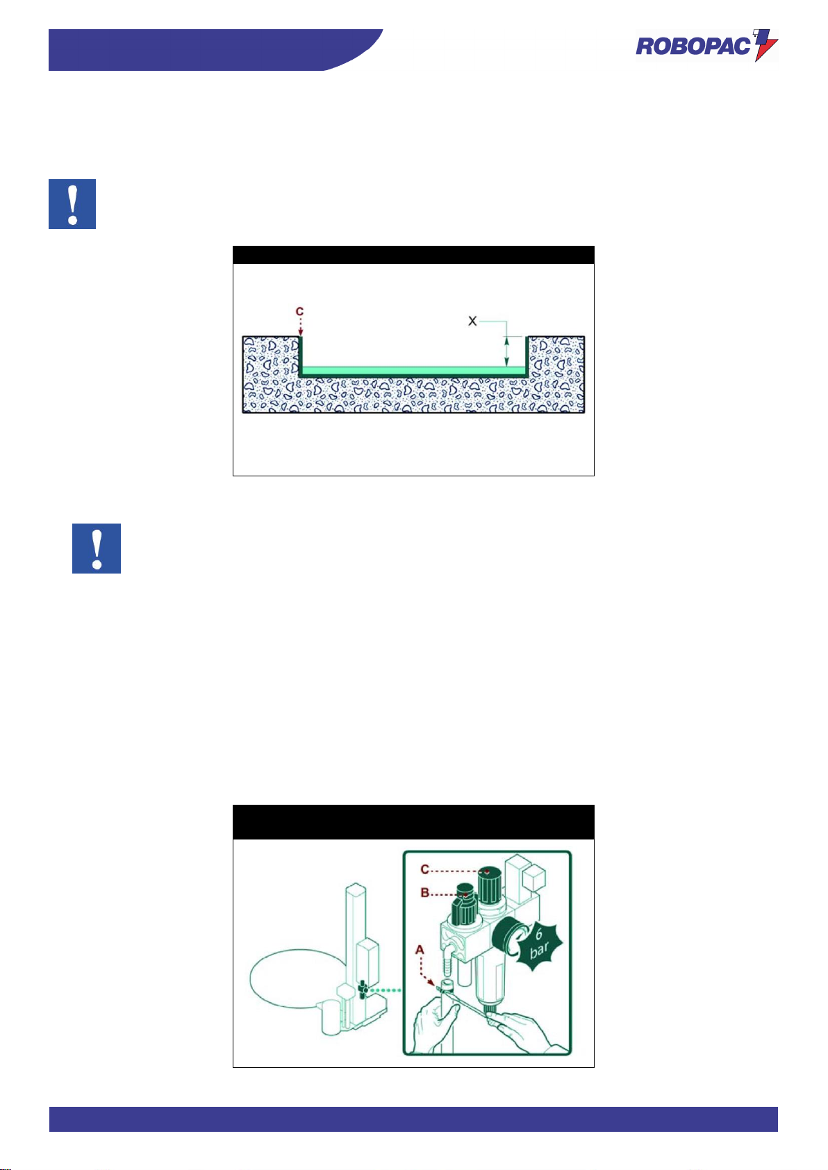
ENG
INFORMATION ON HANDLING AND INSTALLATION
66
4.7. MACHINE UNDERGROUND INSTALLATION
Dig a pitch in the floor to insert the template (C) and fix it with a concrete casting.
The template (C) is supplied on request (Optional).
Important
The depth (X) must be equal to the machine base height.
Rotoplat 308-508-708
4.8. RECOMMENDATIONS FOR CONNECTIONS
Important
The connections must be made in accordance with the specifications supplied by the Manufacturer in
the enclosed diagrams. The person authorised to carry out said operation must have the skills and
experience acquired and acknowledged in the specific sector, must perform the connection in
accordance with the best practice and take into account all the regulatory and legislative requirements.
Once the connection has been completed, before commissioning the machinery, it is necessary to
perform an overall check to verify if said requirements have been complied with.
4.9. PNEUMATIC CONNECTION
1. Insert a flexible hose in the end of the hose barb fitting and fasten it with a metallic screw clamp (A).
2. Check that the valve (B) is in the “OPEN” position.
3. Activate the supply line pressure.
4. Check that the pressure gauge indicates at least 6 bar and use the knob (C) to compensate any pressure
difference.
Repeat this operation when the machine is running.
Rotoplat LP 308-508-708
Rotoplat TP3 308-508-708
Page 67
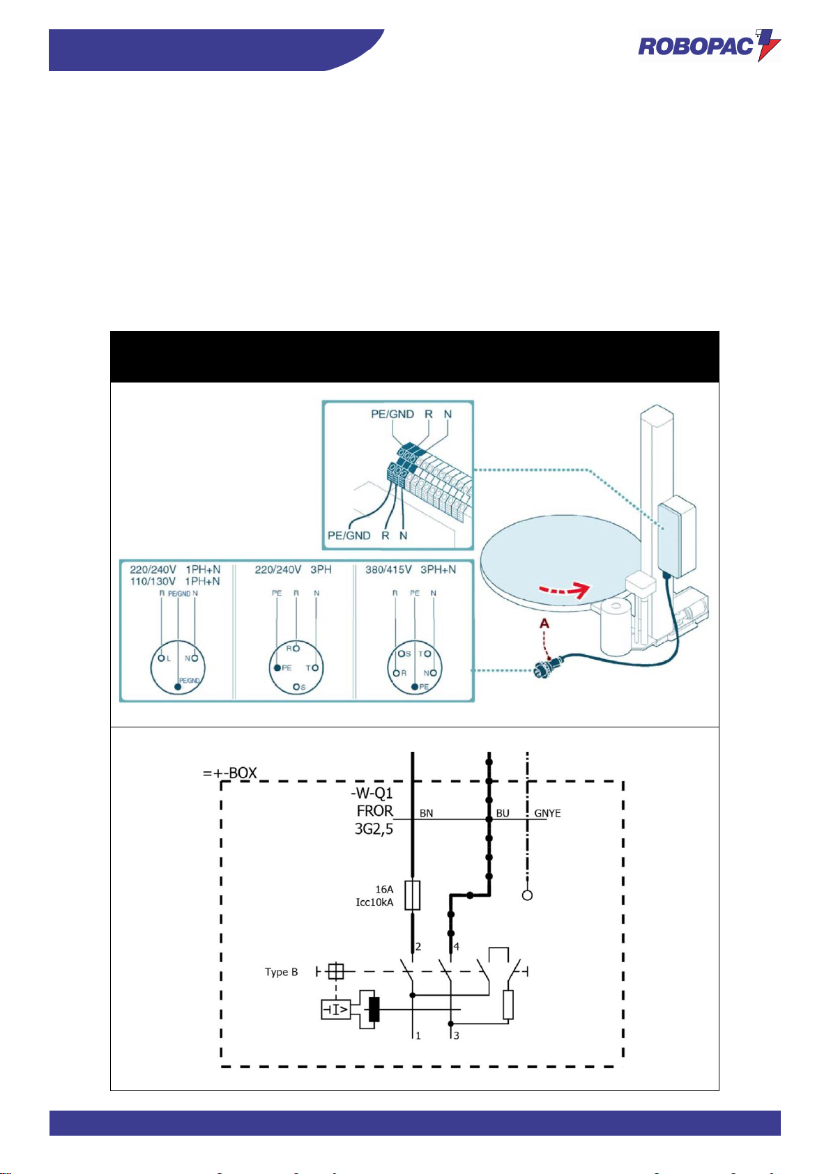
67
INFORMATION ON HANDLING AND INSTALLATION
ENG
4.10. ELECTRICAL CONNECTION
Proceed as follows for the electrical connection.
1. Check that the line voltage (V) and frequency (Hz) correspond to those of the machine (See identification plate
and wiring diagram).
2. Turn main switch to pos. 0 (OFF).
3. Connect the power cable (if supplied) to the socket (A), as shown in the figure, in accordance with the mains
supply.
4. The earth wire (yellow–green) must be connected to its earth terminal PE.
5. Power the machine using the main switch.
6. Press the “Reset” button.
7. When the “Start” button is pressed, the plate should turn anticlockwise.
8. Provided by the customer.
Rotoplat 308-508-708
Rotoplat LP 308-508-708
Rotoplat TP3 308-508-708
Page 68

ENG
INFORMATION ON ADJUSTMENTS
68
5. INFORMATION ON ADJUSTMENTS
5.1. RECOMMENDATIONS FOR ADJUSTMENTS
- Before performing any operation, the authorised operator must make sure to have understood the
“Instructions for use”.
- Activate all the safety devices provided, stop the machine and assess whether there is any residual energy
before carrying out the operations.
- Provide suitable safety conditions in compliance with the regulations on workplace safety to prevent and
minimise the risks.
- Pay attention to the safety warnings, do not misuse the machine and assess the possible residual risks.
Page 69
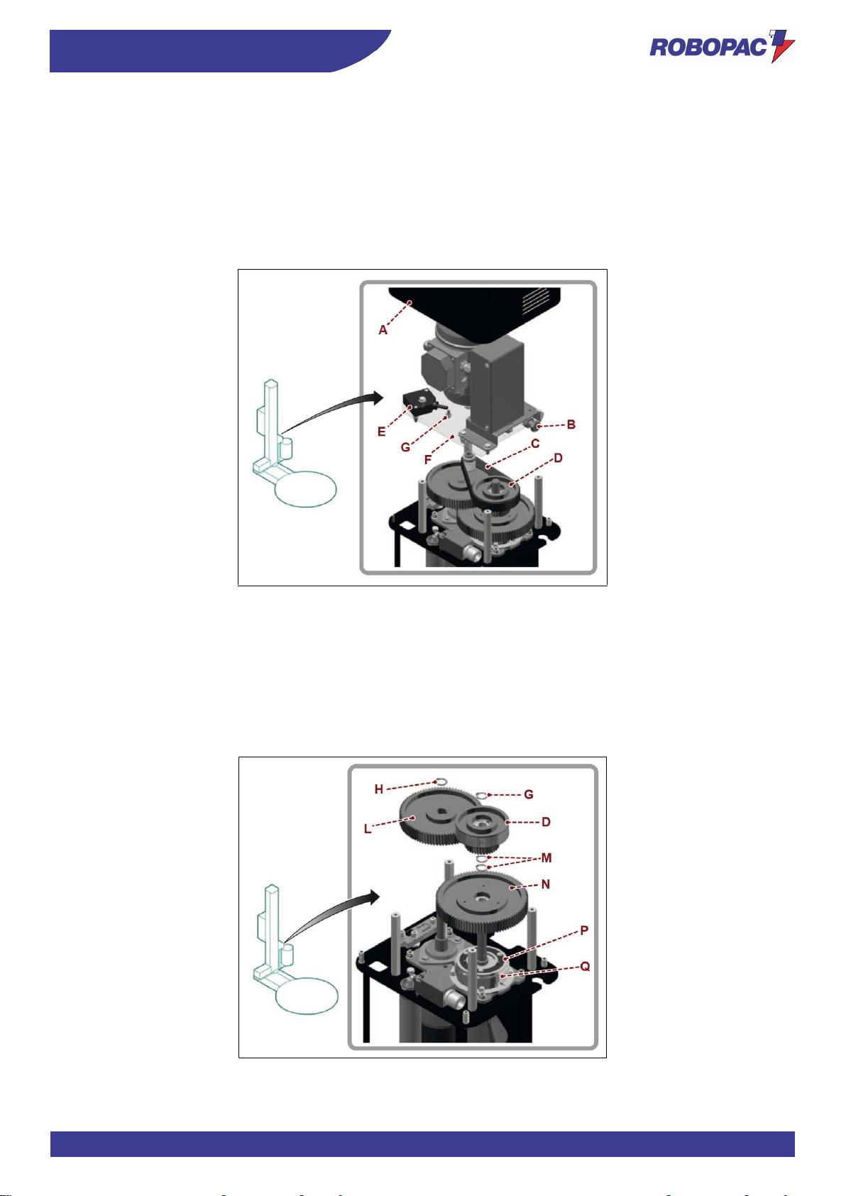
69
INFORMATION ON ADJUSTMENTS
ENG
5.2. ADJUSTING THE “CARRIAGES”
5.2.1. SPOOL CARRIAGES OF "PDS" TYPE (PRE-STRETCH GEAR REPLACEMENT)
1. Stop the machine in safety conditions.
2. Remove the guard (A).
3. Slacken the belt (C) using the tensioner (B).
4. Slide the belt out of the pulley (D).
5. Loosen the screws (E).
6. Remove the plate (F) with motor and bearings.
7. Remove the retaining ring (G).
8. Remove the pulley (D).
9. Remove the retaining ring (H).
10. Remove the gear (L).
11. Remove the retaining ring (M).
12. Remove the gear (N).
13. Loosen the screws and remove the disc (P) from the gear (N).
14. Select the set of gears (L-N) relating to the concerned pre-stretch rate (see table).
Page 70
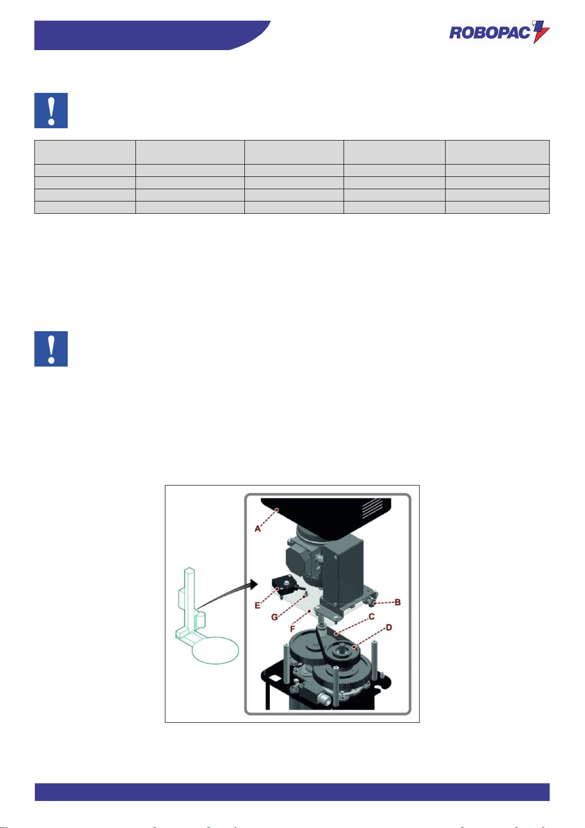
ENG
INFORMATION ON ADJUSTMENTS
70
The table indicates the pre-stretch values which can be obtained with the relevant transmission gear set.
Important
Set the pre-stretch according to the film resistance and quality in order to obtain a low consumption.
Pre-stretch
percentage
Gear code (L)
No. of gear teeth (L)
Gear code (N)
No. of gear teeth (N)
150%
2540300068
34
2540300070
85
200%
2540300003
29
2540300002
90
250%
2540300165
25
2540300164
94
300%
2540300027
24
2540300028
95
15. Fit the disc (P) and correctly fasten it to the gear (Q) of the new transmission ratio.
16. Fit the gear (N) of the new transmission gear set.
17. Position the gear with the disc side (P) coupled with the clutch (Q).
18. Fit the retaining ring (M).
19. Fit the gear (L) of the new transmission gear set.
20. Fit the retaining ring (H).
21. Fit the pulley (D).
22. Fit the retaining ring (G).
Important
During reassembly phases, make sure that coupling tabs are correctly
inserted.
23. Rest the plate (F) on the stud bolts, paying attention to fit the belt (C) on the pulley (D).
24. Tighten the screws (E).
25. Tension the belt (C) using the tensioner (B).
26. Manually turn the pre-stretching rollers in both directions to correctly seat the coupling between belt and
pulleys.
27. Check the belt tensioning again and properly adjust it if necessary.
28. Refit the guard (A) when finished.
Page 71
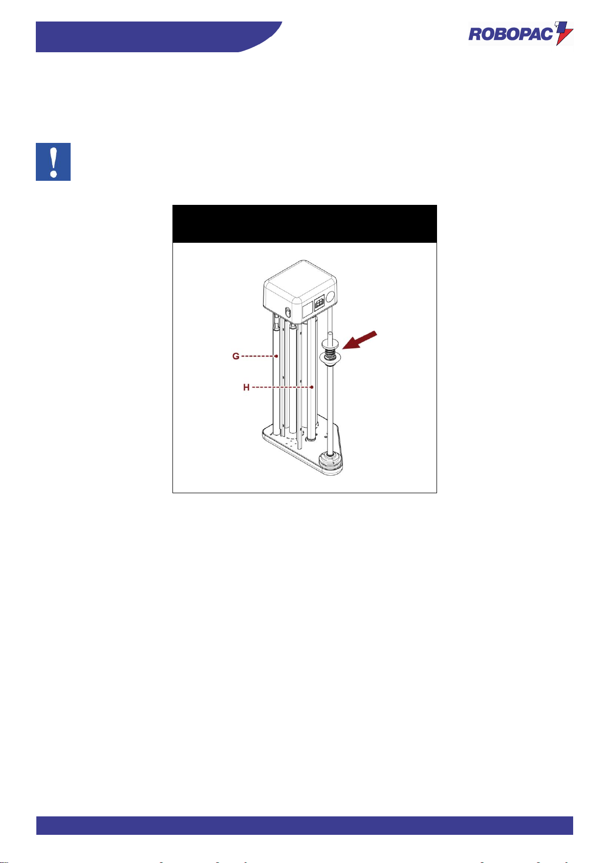
71
INFORMATION ON ADJUSTMENTS
ENG
5.2.2. SPOOL CARRIAGES OF "FR for mesh" TYPE
1. Press the stretching button (See “6.4”) until reaching the value required.
The brake shaft for mesh is an accessory that can be mounted on the carriage later on.
This option allows the system to use a mesh spool with an “FR” std carriage.
Important
For a correct tensioning of the mesh, adjust the braking effect so that the outfeed roller (G) is more braked
than the infeed roller (H); moreover, it is necessary to avoid braking the stretching rollers too much to
prevent the mesh from slipping.
Rotoplat 308
Rotoplat TP3 308
Rotoplat LP 308
Page 72
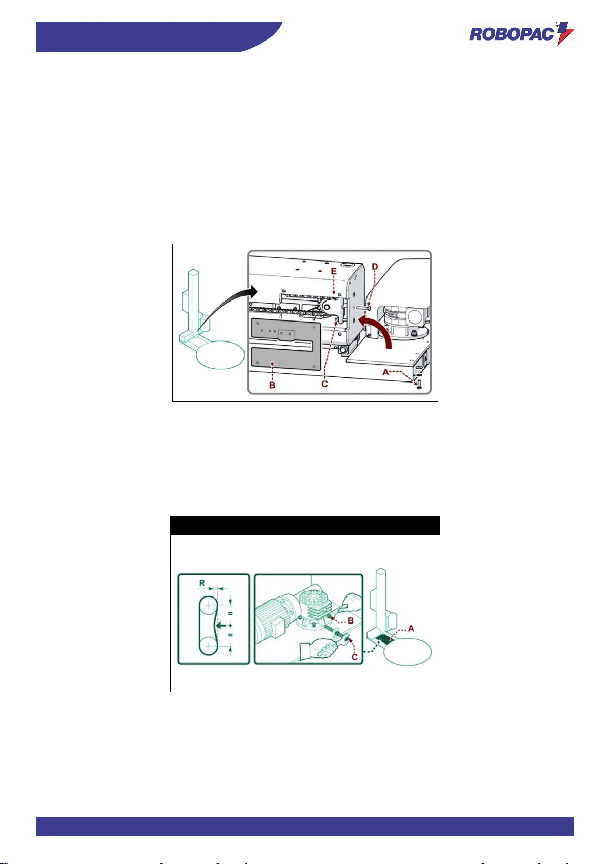
ENG
INFORMATION ON ADJUSTMENTS
72
5.3. SPOOL CARRIAGE LIFTING CHAIN ADJUSTMENT
1. Lift the spool carriage (with the machine operating in “manual mode”) until it reaches the “upper” limit switch.
2. Switch the machine off.
3. Loosen the screws (A) and tilt the pole resting it on the plate.
4. Remove the guard (B).
5. Loosen the nuts (C).
6. Tighten the screw (D) "M8x50 UNI 5739" (not supplied) with a torque wrench (not supplied) to the torque of 3
Nm.
7. Screw the nuts (C) again until reaching the chain tensioner (E) level.
8. Loosen the screw (D).
9. Refit the guard (B).
10. Place the pole back in its vertical position and tighten the screws (A).
5.4. ROTARY TABLE CHAIN ADJUSTMENT
1. Remove the cover (A).
2. Loosen the fastening screws (B) of the reduction unit.
3. Tighten the screw (C) with a torque wrench (not supplied) to 5 Nm.
4. Tighten the reduction unit fastening screws (B) when adjustment is completed.
5. Refit the guard (A).
Rotoplat 308-508-708
Page 73
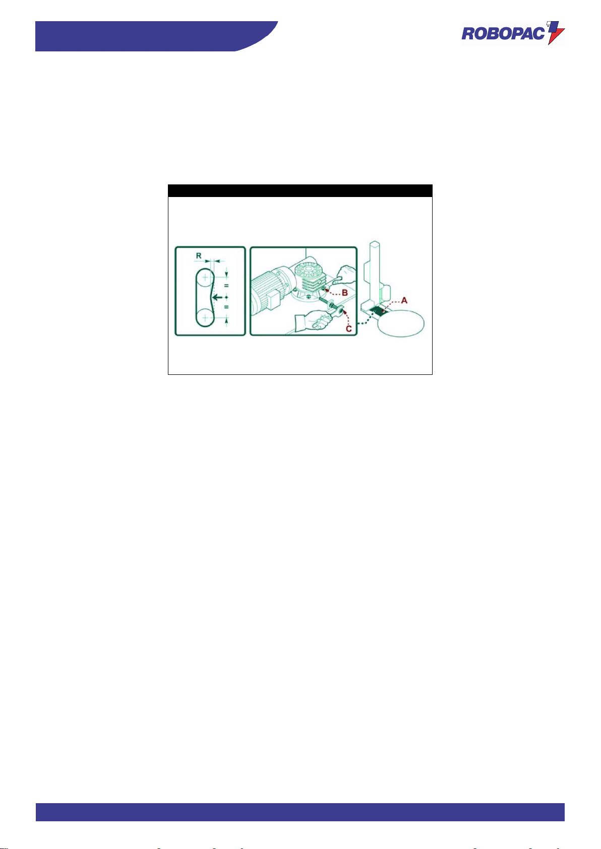
73
INFORMATION ON ADJUSTMENTS
ENG
5.5. “TP3” TABLE ROTATION CHAIN ADJUSTMENT
1. Loosen the screw (C) completely.
2. Remove the cover (A).
3. Loosen the fastening screws (B) of the reduction unit.
4. Tighten the screw (C) with a torque wrench (not supplied) to the rated torque of 3Nm.
5. Tighten the reduction unit screws (B) when adjustment is completed.
6. Loosen the screw (C) completely and refit the guard (A).
Rotoplat TP3 308-508-708
Page 74
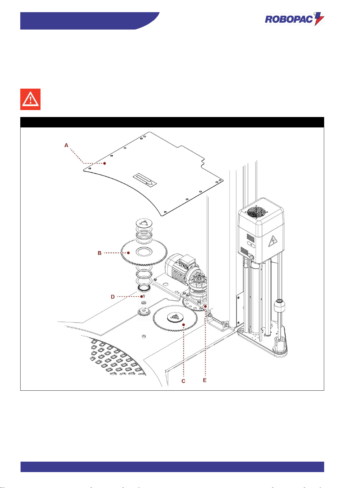
ENG
INFORMATION ON ADJUSTMENTS
74
5.6. ADJUSTING ROTARY TABLE GEAR WHEELS
1. Remove the cover (A).
2. Loosen the fastening screws (E) and correctly position the gearmotor / gear wheel.
3. Loosen the fastening screws (D) of the gear wheels (B) and (C)
4. This adjustment must be performed at the operator’s discretion by using the proper tools.
Danger - warning
Any maintenance operation in this area must be carried out with machine stopped, with electric switch set
to OFF and with no other operator near the machine.
Rotoplat LP 308-508-708
Page 75
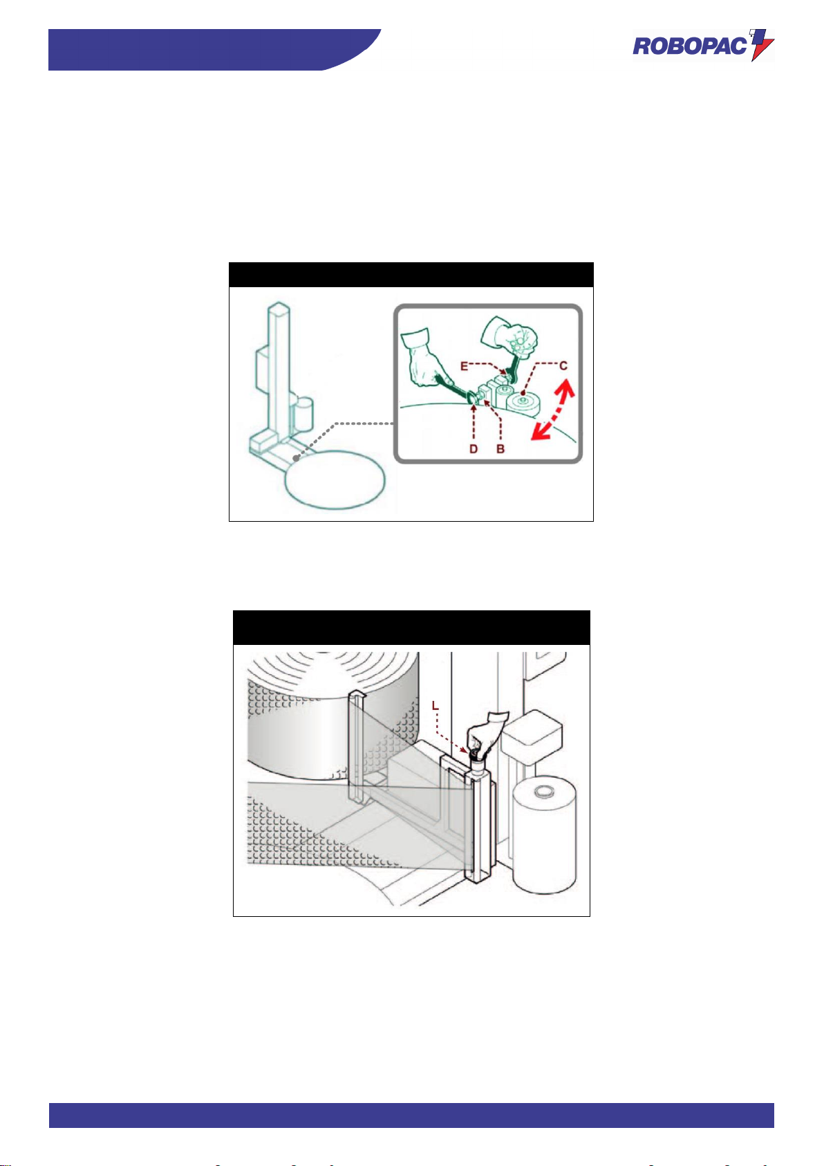
75
INFORMATION ON ADJUSTMENTS
ENG
5.7. ADJUSTING THE TABLE GUIDE WHEELS
1. Remove the cover (A).
2. Loosen the fastening nuts (B).
3. Loosen the screw (E).
4. Tighten the screw (D) so that the wheel (C) is pressed against the rotary plate by approximately 4 mm.
5. Tighten the screw (E).
6. Tighten the nuts (B).
7. Refit the guard (A).
Rotoplat TP3 308-508-708
5.8. “BUBBLE WRAP” SPOOL BRAKING ADJUSTMENT
1. To tension the film correctly, work on the handwheel (L) which adjusts the spool braking.
Rotoplat 108-308-508-708
“BUBBLE WRAP”
Page 76

ENG
INFORMATION ABOUT THE USE
76
6. INFORMATION ABOUT THE USE
6.1. RECOMMENDATIONS FOR OPERATION AND USE
- When using the machine for the first time, the operator must read the manual and identify the control functions
and simulate some operations, especially machine start and stop.
- Make sure that all safety devices are properly installed and efficient.
- Only carry out the operations foreseen by the Manufacturer and do not tamper with any device to obtain
different performance levels.
- Daily, before each use of the machine, check that it stops by pressing the emergency button to trigger the
bumper.
Caution - warning
Bumper can be triggered by placing an obstacle in front of the machine at a distance of approximately
20 cm.
Important
The frequency of the accidents derived from machine use depends on many factors that cannot always
be foreseen and controlled.
Some accidents may be caused by unpredictable environmental factors, others are mainly due to
users’ behaviours.
On first use, and if required, in addition to being authorised and appropriately informed, the personnel
must simulate some manoeuvres to identify the main controls and functions.
Only carry out the operations foreseen by the Manufacturer and do not tamper with any device to
obtain different performance levels.
Make sure the safety devices are properly installed and efficient before use.
Users, besides complying with these requirements, must apply all the safety regulations and carefully
read the descriptions of the controls and commissioning.
Page 77
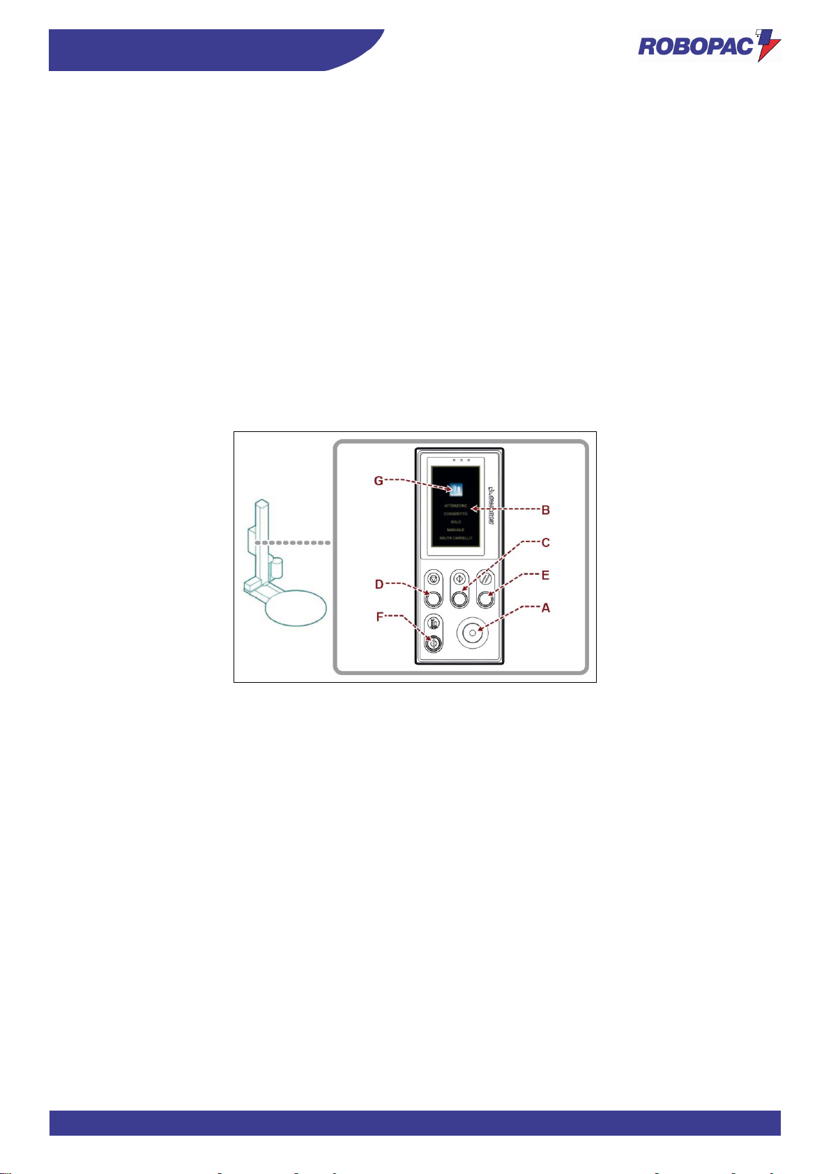
77
INFORMATION ABOUT THE USE
ENG
6.2. DESCRIPTION OF THE CONTROLS
1) Emergency stop button:
it is used in case of imminent risk to stop, with a voluntary action, the machine parts which may pose a risk.
For more details, see the paragraph “Description of safety devices”.
2) User interface:
it is used to set or modify the machine operating parameters.
For more details, see the paragraph “Description of user interface”.
3) “Cycle start” button:
it is used to start the wrapping automatic cycle.
4) “Cycle stop” button:
it is used to stop the wrapping automatic cycle.
5) “Reset” button:
it is used to reset the machine before restarting it after an emergency stop or after a shut-down due to the
disconnection of the power supply.
6) Emergency override key-operated switch:
it is used to temporarily bypass the carriage emergency.
When the key is turned to position I (hold to run), the user interface screen will display the page “safety device
override” and this allows, by pressing the button (7), to lift only the carriage.
Page 78
ENG
INFORMATION ABOUT THE USE
78
6.3. DESCRIPTION OF USER INTERFACE
The user interface is equipped with an active matrix “touch screen” colour display.
To view the different functions, just “touch with a finger” the display areas.
The figure shows the functional logic diagram of the “navigation” modes.
There are two controls for automatic packaging cycle: STANDARD and MULTILEVEL CONTROL (from the “layer
home” page).
MULTILEVEL CONTROL allows breaking down the product height in 5 different levels with adjustable thickness and,
for each one of them, it is possible to adjust film stretch, pre-stretch (only on motorised carriages), reinforcement
wrapping turns, machine rotation speed and carriage speed.
Each one of the 5 levels can be set with values depending on the carriage movement direction, namely also with
different values for upstroke and downstroke.
No.
Name
Description of the function
1
“Home” page
The page is displayed upon the activation of the
reset control.
The page displays the wrapping values currently
in use and gives
access to the other pages.
1.1
“Layer home” page
The page is displayed upon the activation of the
control on the right
of the various recipes from the “recipes” page.
The page displays the wrapping values currently
in use and gives access to the other pages
2
“Manual handling” page
The page displays the controls to activate the
handling of functions in “manual mode”.
3 – 3.1
“RECIPES” page
The page displays the controls to activate the
concerned recipe.
4
“Wrapping cycle” page
The page displays the controls to activate the
wrapping cycle
5
“General parameters” page
The page displays the controls to program the
machine set-up parameters
6
“Production counters (pallets)” page
The page displays the controls to check the
quantity (partial and total) of the pallets made
7
“(H.M.I.) enabling” page
The page displays the controls to customise the
user interface operating mode
8
“Change password” page
The page displays the controls to change the
password to access protected functions
9
“Enter password (user login)” page
The page displays the controls to enter the
password (relating to the selected user) to
access the protected functions.
10
"Service” page
The page is reserved to the Manufacturer’s
Service support only, to perform diagnostics and
basic programming.
For details on the listed pages, see the description in the specific paragraph.
Page 79
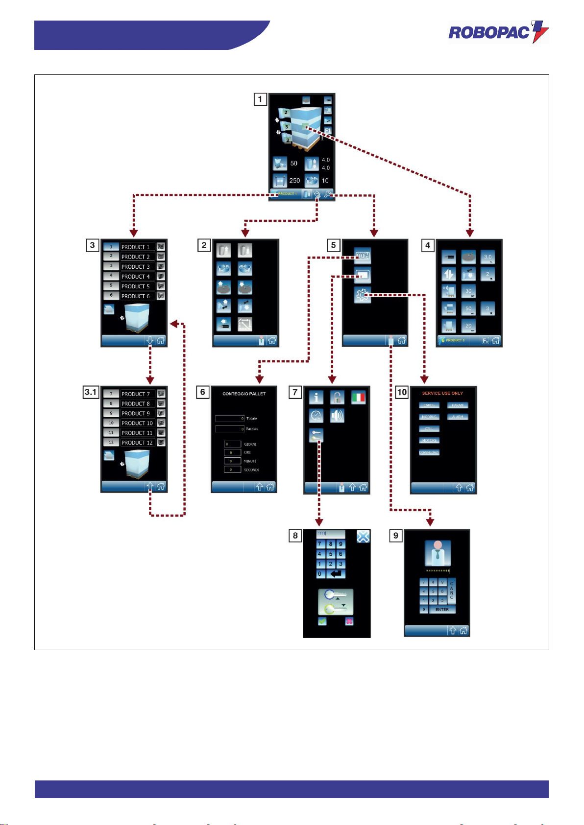
79
INFORMATION ABOUT THE USE
ENG
Page 80
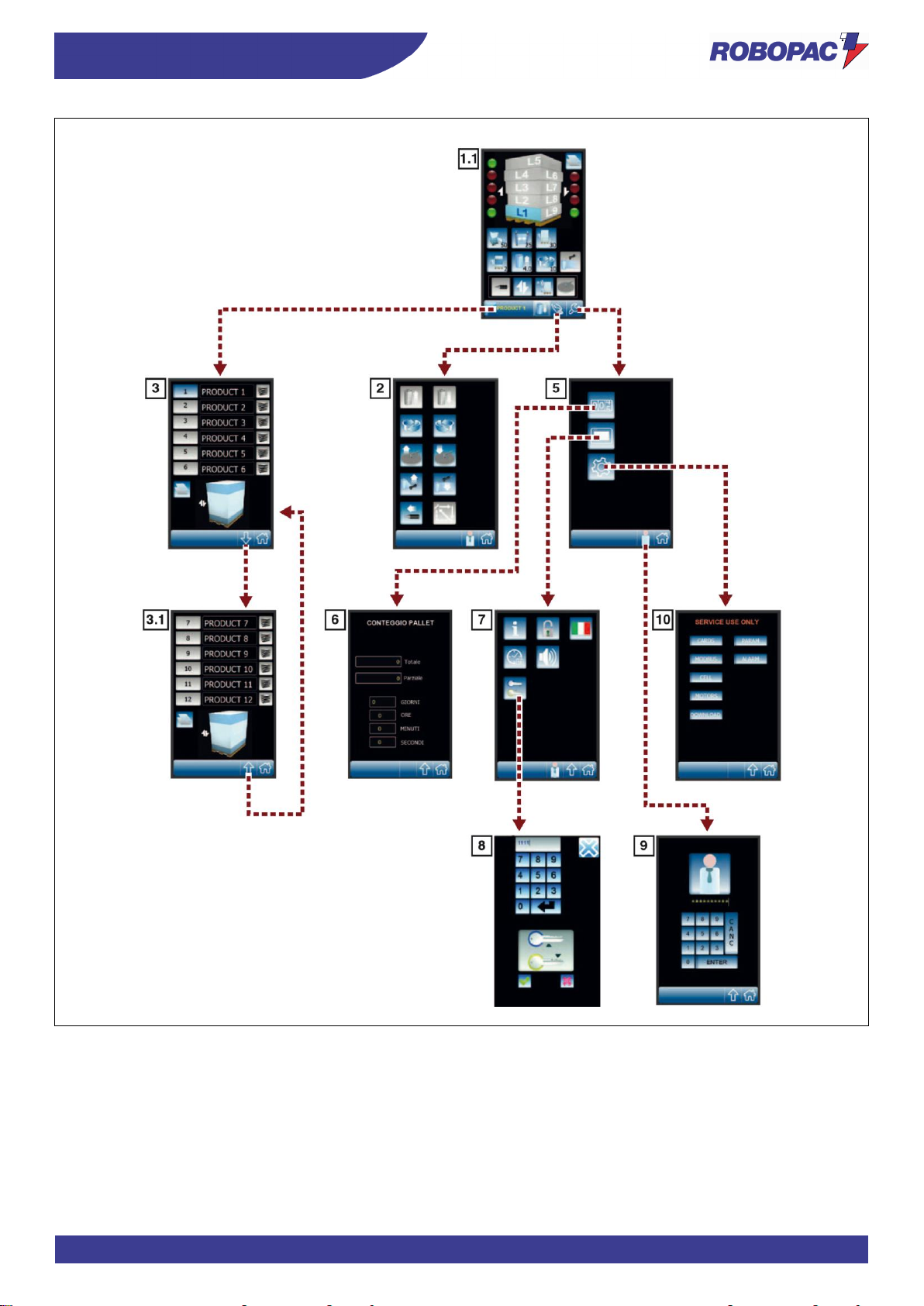
ENG
INFORMATION ABOUT THE USE
80
Page 81
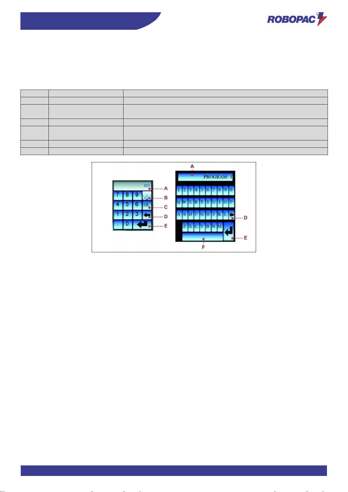
81
INFORMATION ABOUT THE USE
ENG
6.3.1. NUMERICAL AND ALPHANUMERICAL KEYBOARD
Some values, displayed in the areas of each single page, can be properly programmed.
The keyboard is displayed each time that an editable or programmable area is pressed.
After entering the characters (numerical or alphabetical), press the button to confirm.
The new value will appear in the selected area.
No.
Name
Description of the function
A
Display area
The area displays the numerical and alphabetical characters entered
B
Button
Activating the control will close the page and the values entered will not be
saved.
C
Button
Activating the control will delete the selected character
D
Button
Activating the control will delete one character at a time (starting from the
last one on the right).
E
Button
Activating the control will save the value or the text entered
F
Button
Activating the control will perform the functions of the “space bar”
Page 82
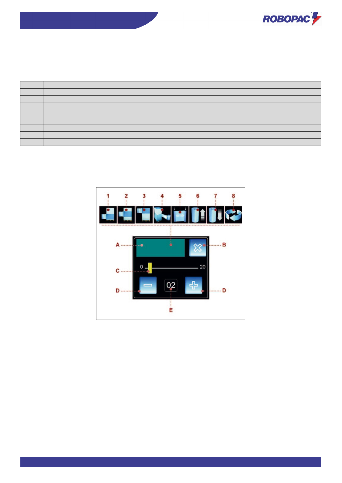
ENG
INFORMATION ABOUT THE USE
82
6.3.2. PROGRAMMING WINDOW
The window is displayed each time that an editable or programmable area is pressed.
A) Area: it displays the icon corresponding to the concerned parameter to be programmed.
The figure shows a typical example of window and the table includes the description of the icons.
Icon
Description of the function
1
Lower wrapping
2
Reinforcing wrapping
3
Upper wrapping
4
Film stretch
5
Film pre-stretch
6
Carriage upstroke speed
7
Carriage downstroke speed
8
Table rotation speed
B) Button: it is used to close the programming window.
C) Bar: it is used to (quickly) increase or decrease the value displayed in the area (E).
D) Buttons: they are used to increase or decrease (one unit at a time) the value displayed in the area (E).
E) Area: it displays the programmed parameter value.
Page 83
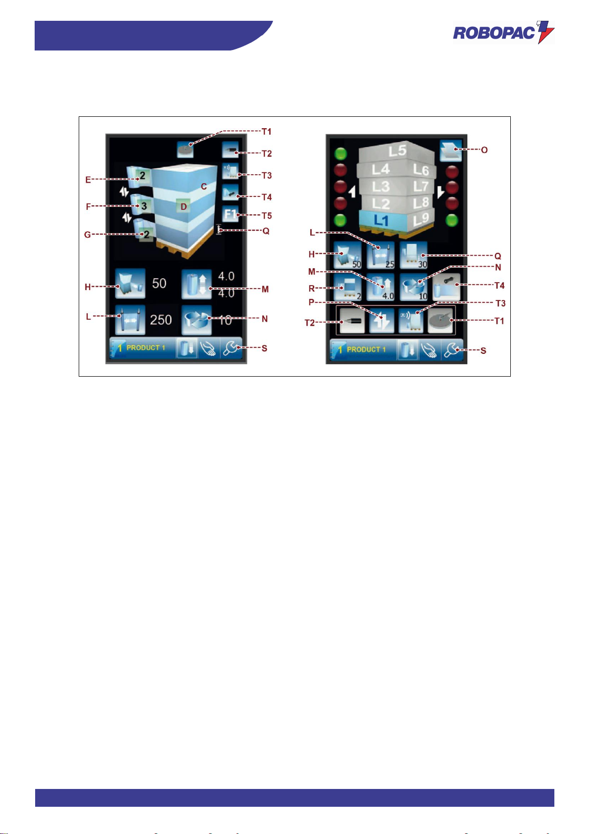
83
INFORMATION ABOUT THE USE
ENG
6.4. “HOME” PAGE
The page displays the wrapping values currently in use and gives access the other pages.
C) Area:
it displays the preview of the selected pallet wrapping cycle.
D) Button:
it is used to display the “wrapping cycle” page.
E) Button:
it is used to program the number of wrappings in the upper end of the pallet.
The displayed number indicates the programmed value.
F) Button:
it is used to program the number of reinforcing wrappings in the intermediate area of the pallet.
The displayed number indicates the programmed value.
G) Button:
it is used to program the number of wrappings at the base of the pallet.
The displayed number indicates the programmed value.
H) Button:
it is used to program the film stretch value.
The displayed number indicates the programmed value.
L) Button:
it is used to program the film pre-stretch value (only for “PDS” - “PVS” carriages).
The displayed number indicates the programmed value.
M) Button:
it is used to program the speed of the carriage vertical movement.
The displayed number indicates the programmed value.
N) Button:
it is used to program the machine wrapping speed.
The displayed number indicates the programmed value.
O) Button:
it is used to copy the data from one layer to another.
P) Wrapping cycle.
Q) Distance from the ground at wrapping start.
R) Reinforcing wrapping programming.
Page 84
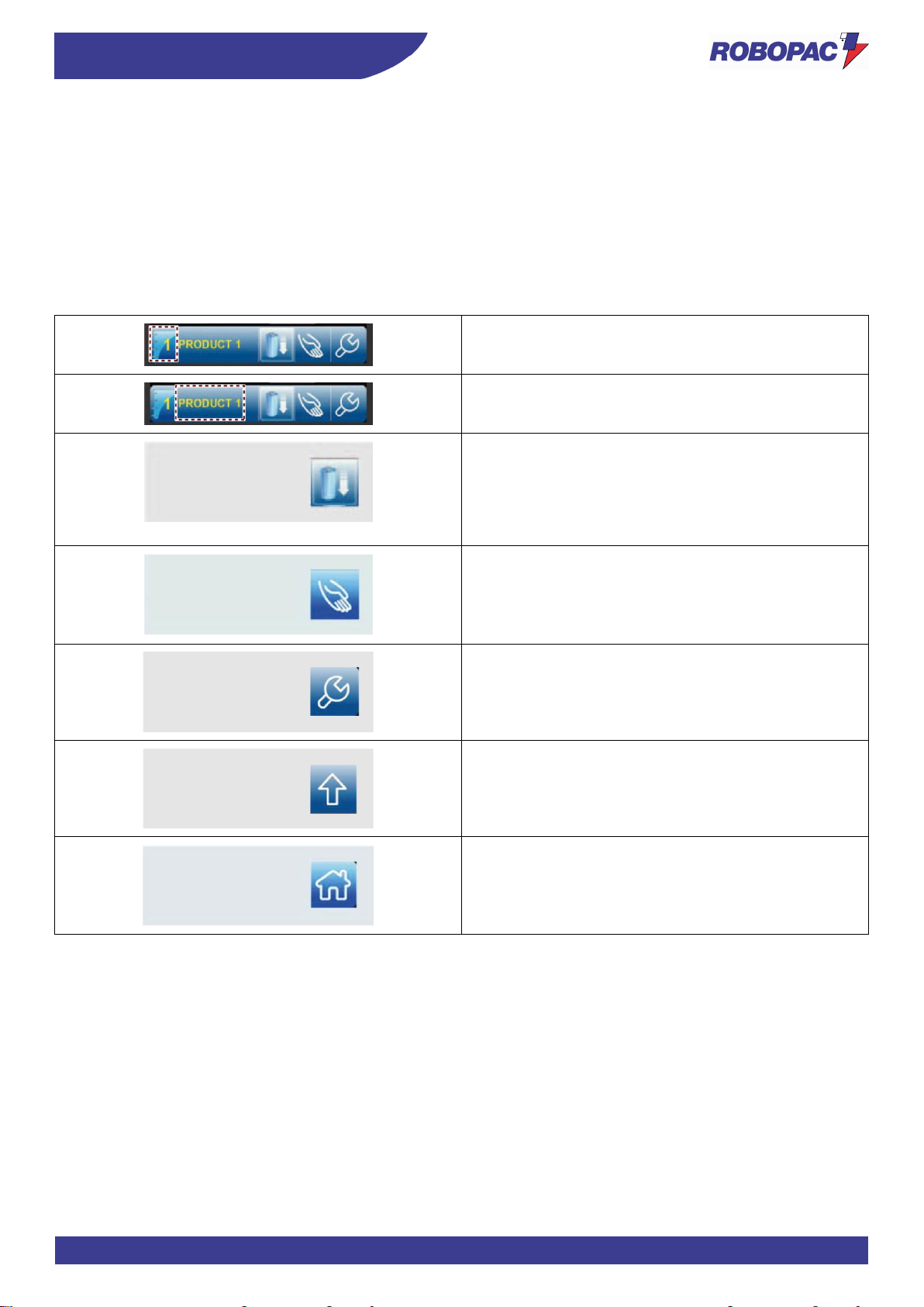
ENG
INFORMATION ABOUT THE USE
84
Some buttons T, described below, may be disabled/hidden depending on the configurations.
T1) Presser.
T2) Cut.
T3) Altimeter.
T4) Creasing head.
T5) F1 Special cycle.
S) Toolbar:
The toolbar is displayed in every page and features only the buttons which can be activated.
The list includes the description of the elements (buttons, icons, etc.) displayed in the area.
Button:
it is used to display the “recipes” page.
The displayed number indicates the active recipe.
Area:
it displays the name of the active recipe.
Button (jog):
it is used to move the carriage back to the lower limit
switch.
When the carriage is at the lower limit switch, the button
is not displayed.
Press the “cycle stop” button to stop the movement.
Button:
it is used to display the “manual handling” page.
Button:
it is used to display the “general parameters” page.
Button:
it is used to display the upper level page.
Button:
it is used to display the “home” page.
Page 85
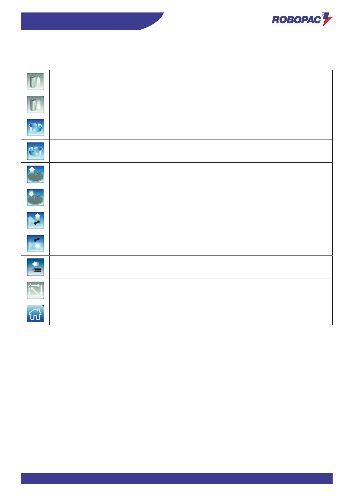
85
INFORMATION ABOUT THE USE
ENG
6.5. “MANUAL HANDLING” PAGE
The page displays the controls to activate the spool carriage vertical movement in “manual mode”.
Button (hold to run): it is used to activate the carriage upstroke.
Button (hold to run): it is used to activate the carriage downstroke.
Button (hold to run): it is used to activate the table clockwise rotation.
Button (hold to run): it is used to activate the table counter-clockwise rotation.
Button (hold to run): it is used to activate the presser arm upstroke.
Button (hold to run): it is used to activate the presser arm downstroke.
Button (hold to run): it is used to activate the creasing head upstroke.
Button (hold to run): it is used to activate the creasing head downstroke.
Button (hold to run): it is used to activate the punch forward movement.
Button (hold to run) it is used to activate the carriage return and the table synchronisation.
Button: it is used to display the “home” page.
Page 86
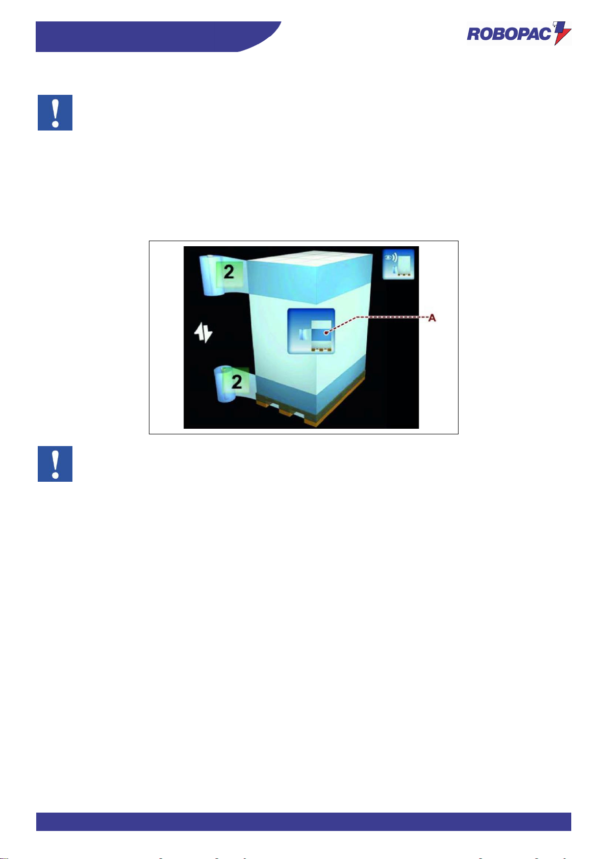
ENG
INFORMATION ABOUT THE USE
86
6.5.1. MANUAL REINFORCEMENT FUNCTION
Important
This function cannot be performed with layered recipes.
When performing a standard recipe, during the carriage upstroke or downstroke, after having performed the wrapping
at the base of the pallet or at its upper end, it is possible to manually perform intermediate wrapping by pressing the
button (A) with two different modes:
- Keep the button (A) pressed to stop the carriage performing reinforcement wrapping until the button is
released.
- Repeatedly press the button (A) to make the carriage perform as many reinforcement wrapping turns as the
times the button has been pressed (1÷9 turns).
Important
The button is visible only during the machine automatic operation.
Page 87
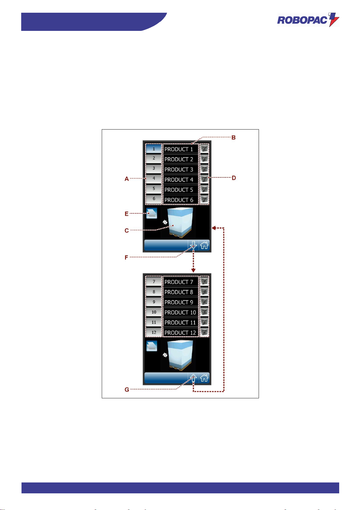
87
INFORMATION ABOUT THE USE
ENG
6.6. “RECIPES” PAGE
The page displays the controls to activate the concerned recipe.
A) Buttons: they are used to activate the concerned recipe.
Red background: function enabled.
B) Buttons: they are used to program the recipe name.
C) Area: it displays the preview of the selected pallet wrapping cycle.
D) Buttons on the RH: they are used to activate the layered cycle.
E) Button: it is used to copy the data from one recipe to another.
F) Button: it is used to display the next recipe page.
G) Button: it is used to display the previous recipe page.
Page 88
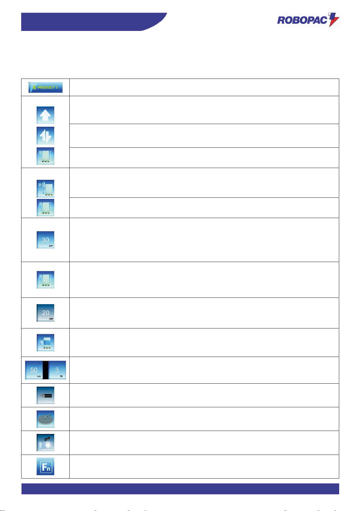
ENG
INFORMATION ABOUT THE USE
88
6.7. “WRAPPING CYCLE” PAGE
The page displays the controls to program the wrapping cycle.
At every activation, the button displays the enabled function with the reference icon.
A) Area: it displays the recipe name and number.
C) Button: it is used to select the type of pallet wrapping cycle.
Icon (C1): it is used to select the “single wrapping” cycle.
Icon (C2): it is used to select the “double wrapping” cycle.
Icon (C3): it is used to select the “double wrapping cycle with feeder”.
D) Button: it is used to select the stop modes (automatic or programmed) of spool carriage during
upstroke.
Icon (D1): it is used to select the automatic stop of the spool carriage (upstroke phase)
depending on the height of the pallet being wrapped.
Icon (D2): it is used to select the programmed stop of the spool carriage (upstroke phase)
depending on the height of the pallet.
Enabling this button, (altimeter) will display another button next to button (E) to set the pallet
height.
To obtain a wrapping delay when this function is active, it is necessary to set a height greater
than that of the product to be wrapped.
E) Button: it is used to program the delay of the stopping point of the spool carriage during the
upstroke phase (only with automatic stop).
F) Button: it is used to enable and disable the programming of the distance from the ground
(offset) at the beginning of wrapping.
- Blue background: Function enabled.
- Grey background: Function disabled.
G) Buttons: they are used to program the positioning value and the number of reinforcing
wrappings.
The buttons are visible only if the function has been enabled with the button (F).
H) Button: it is used to enable and disable the reinforcing wrapping programming mode.
- Blue background: Function enabled.
- Grey background: Function disabled.
L) Buttons: they are used to program the positioning value and the number of reinforcing
wrappings.
The buttons are visible only if the function has been enabled with the button (H).
M) Button: it is used to enable and disable the cutting cycle programming mode (Optional).
N) Button: it is used to enable and disable the presser cycle programming mode (Optional).
O) Button: it is used to enable and disable the creasing head cycle programming mode
(Optional).
P) Button: it is used to access the page of special cycles (F1, F2,...).
Page 89
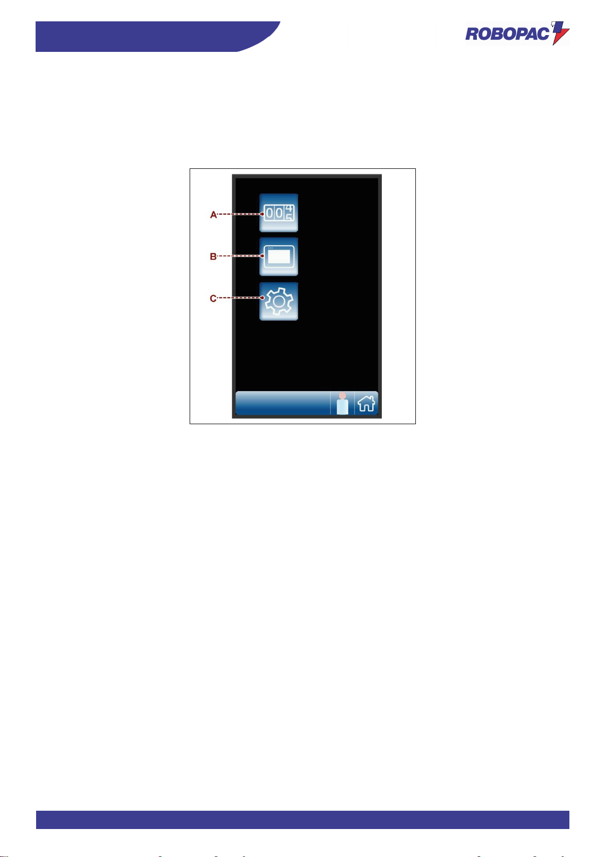
89
INFORMATION ABOUT THE USE
ENG
6.8. “GENERAL PARAMETERS” PAGE
The page is used to program the machine operating parameters.
A) Button: it is used to display the “production counters (pallets)” page.
B) Button: it is used to display the “H.M.I. settings” page.
C) Button: it is used to display the “service” page.
Page 90
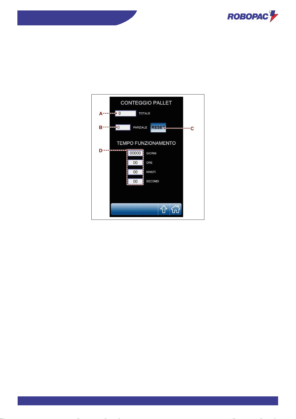
ENG
INFORMATION ABOUT THE USE
90
6.9. “PRODUCTION COUNTERS (PALLETS)” PAGE
The page displays the controls to check the quantity (partial and total) of the pallets made.
A) Area: it displays the counter (total) of the wrapping cycles performed by the machine.
B) Area: it displays the counter (partial) of the wrapping cycles performed by the machine.
C) Button: it is used to reset counter (B).
The function is active only if the system is accessed by a “machine operator” user (see the “enter password
page (user login)”.
D) Area: it displays the machine operating time in days, hours, minutes and seconds.
Page 91
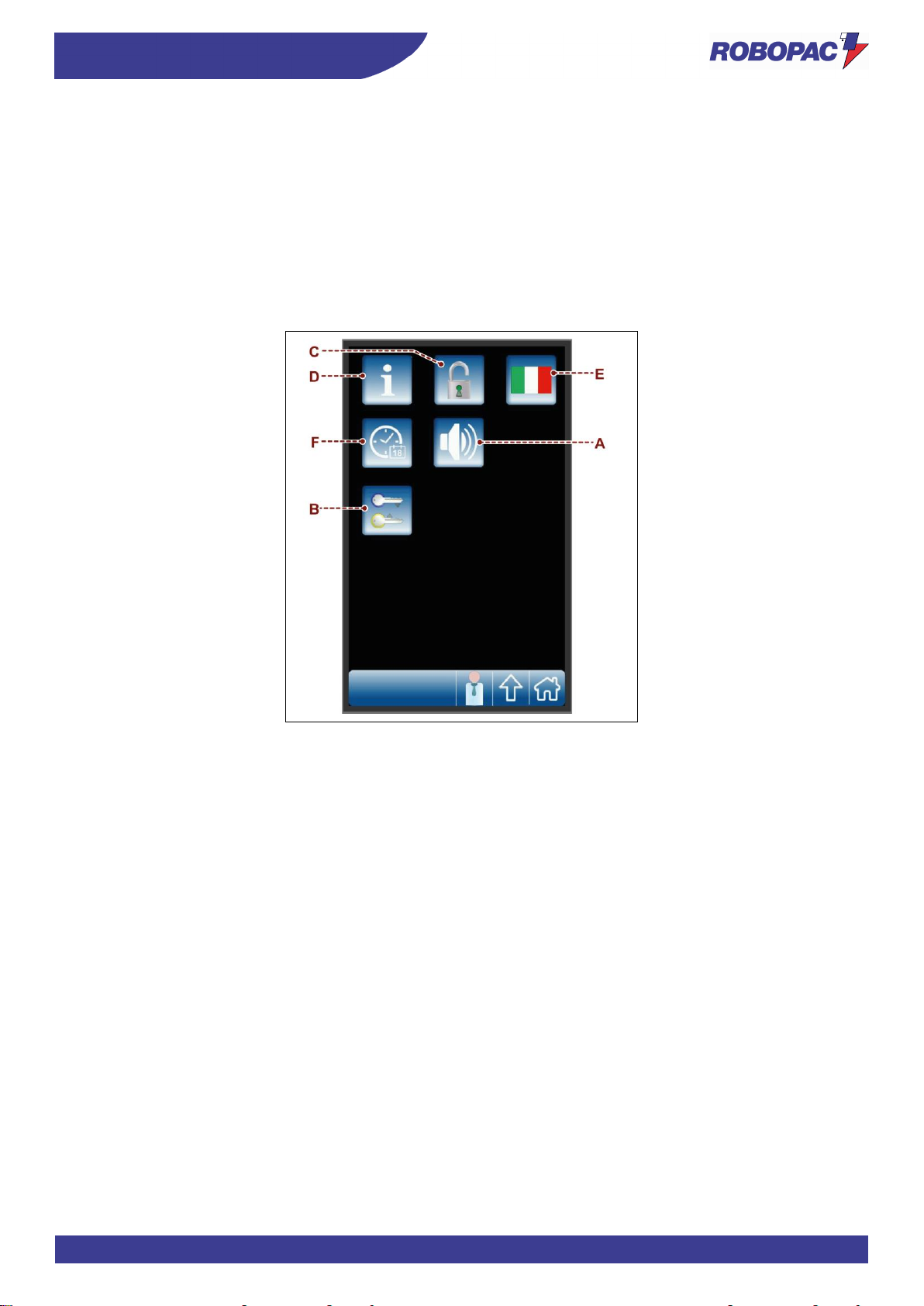
91
INFORMATION ABOUT THE USE
ENG
6.10. “HMI SETTINGS” PAGE
The page displays the controls to customise the user interface operating mode.
A) Button: it is used to enable and disable the display acoustic signal.
B) Button: it is used to display the “change password” page .
C) Button: it is used to enable and disable the recipe programming mode.
The function is active only if the system is accessed by a “machine operator” user (see the “enter password
page (user login)”.
D) Button: it is used to display the page with the software version.
E) Button: it is used to select the language.
F) Button: it is used to display the page for setting date and time.
Page 92
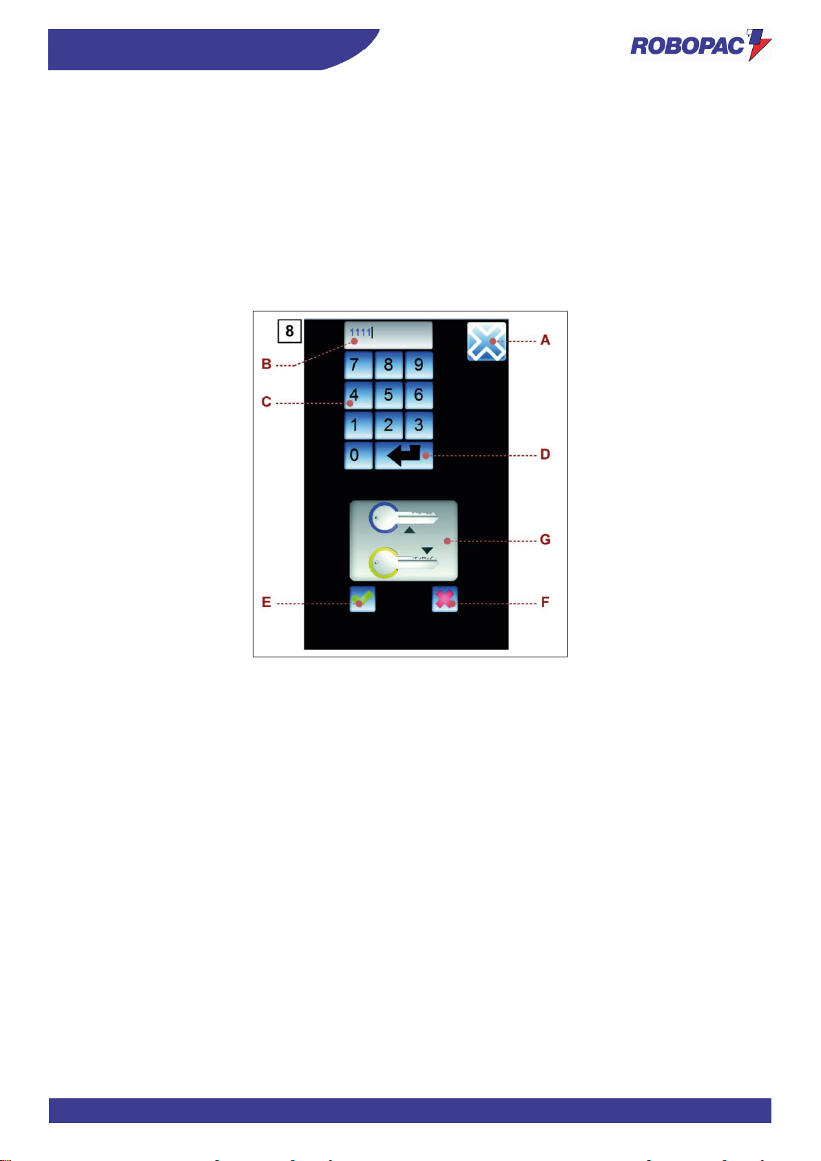
ENG
INFORMATION ABOUT THE USE
92
6.11. “PASSWORD CHANGE” SCREEN
The page displays the controls to change the password to access protected functions.
A) Button: it is used to display the upper level page .
B) Area: it displays the entered characters.
C) Numerical keyboard.
D) Button: it is used to confirm the entered values.
The activation of the control is signalled by the animation of icon (G).
E) Button: it is used to save the password.
The control is enabled only if the animation of icon (G) is active.
F) Button: it is used to reset the entered values.
The activation of the control disables the animation of icon (G).
Page 93
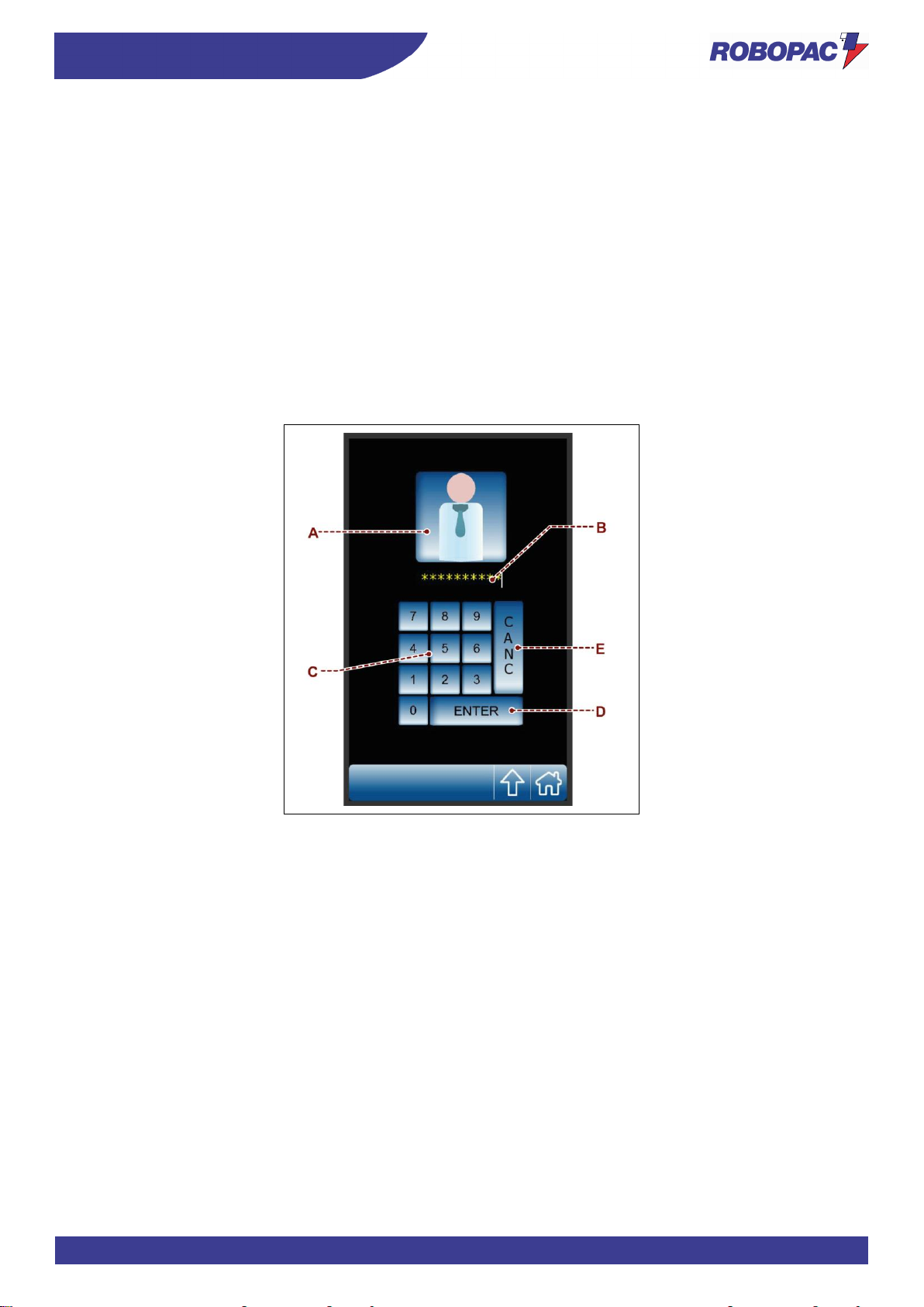
93
INFORMATION ABOUT THE USE
ENG
6.12. “ENTER PASSWORD” SCREEN (USER LOGIN)”
The page displays the controls to enter the password (relating to the selected user) to access the protected functions.
A) Button: it is used to select the type of user concerned.
At every activation, the button displays the enabled function with the reference icon.
- Icon (A1): it is used to select the “machine operator” user.
- Icon (A2): it is used to select the “service support” user.
- Icon (A3): it is used to select the “software administrator” user.
B) Area: it displays the entered characters.
C) Numerical keyboard.
D) Button: it is used to confirm the entered password (login).
To prevent another type of user from accessing the protected functions, use one of the following procedure to
perform the “user logout” at the end of the operations.
- Touch the icon (A1) located in the toolbar.
- Switch the machine off and then on again.
E) Button: it is used to delete incorrect entered values.
Page 94
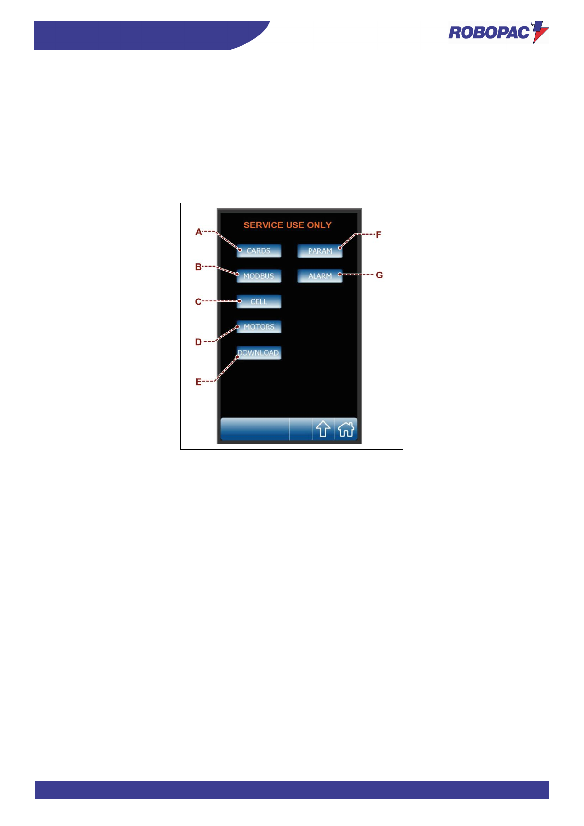
ENG
INFORMATION ABOUT THE USE
94
6.13. "SERVICE” SCREEN
The page is reserved to the Manufacturer’s Service support only, to perform diagnostics and basic programming.
A) Button: it is used to display the status of the various electronic components of the electric control panel.
B) Button: it is used to display the MODBUS status.
C) Button: it is used to display the load cell offset.
D) Button: it is used to display the status of motors.
E) Button: it is used to update the software.
F) Button: it is used to display the machine set-up general parameters.
G) Button: it is used to display the alarm log.
Page 95
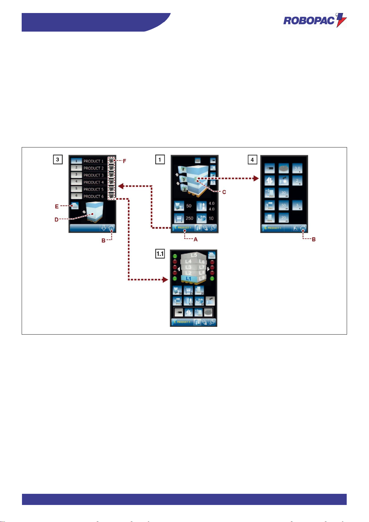
95
INFORMATION ABOUT THE USE
ENG
6.14. NEW RECIPE PROGRAMMING
1. Display the “home” page 1.
2. Press the button (A) to display the “recipes” page 3.
3. Press the button (F), corresponding to the required recipe, to access the “home 1.1.” page.
4. If necessary, press the button (E) to copy the data from one recipe to another.
5. Select the concerned recipe.
6. Set the recipe name.
7. Press the button (B) to display the “home” page 1.
8. Press the button (C) to display the “wrapping cycle” page 4.
9. Set the recipe parameters.
The area (D) displays the preview of the selected pallet wrapping cycle.
10. Press the button (B) to display the “home” page 1.
Page 96
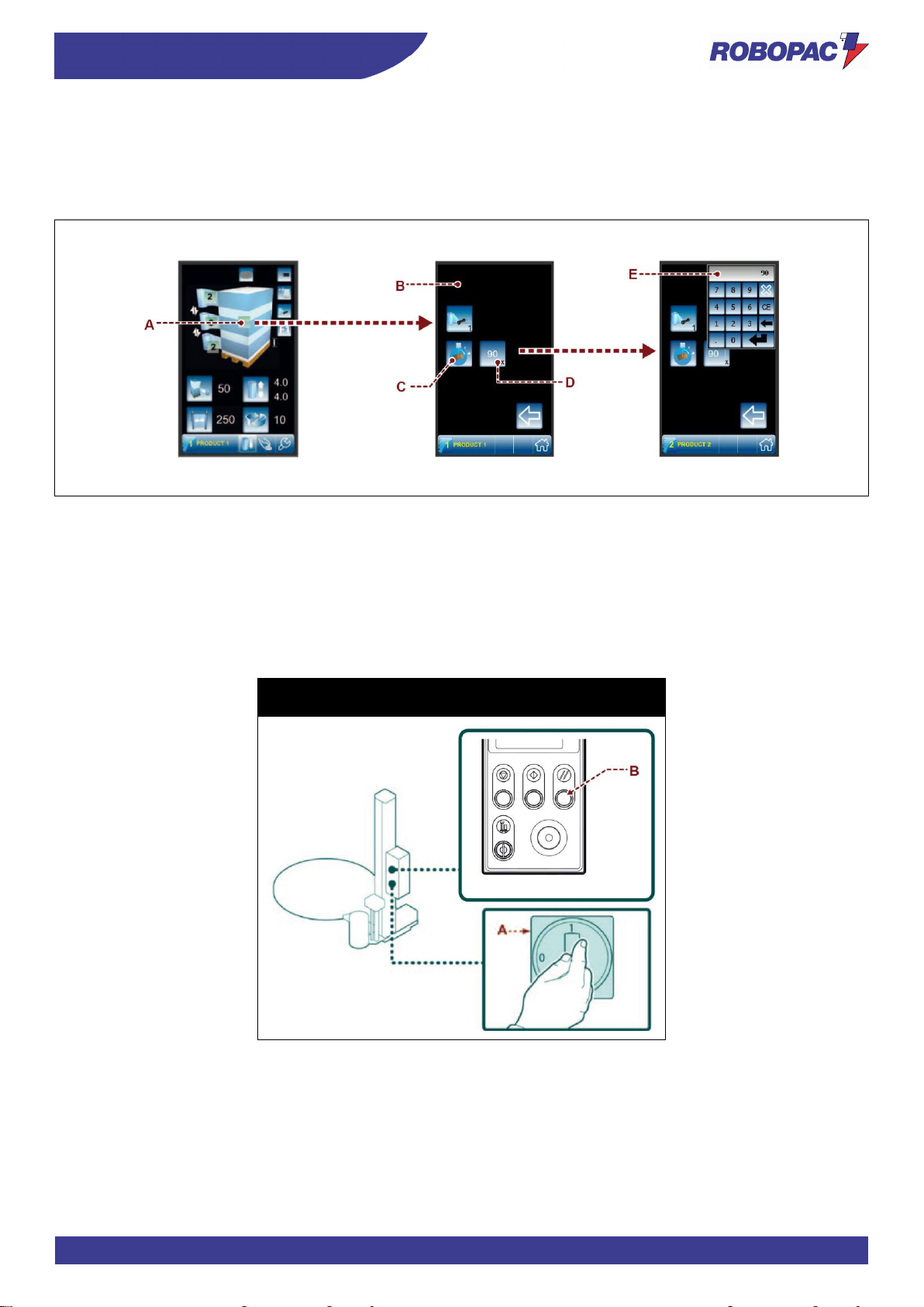
ENG
INFORMATION ABOUT THE USE
96
6.15. PHASE ANGLE ADJUSTMENT
1. Press button (A) to view page (B) where the “Phase angle adjustment” button C is shown.
2. Press button C to display the key to set value D (if the set recipe allows it).
3. Press button D to display the drop-down window E where the new value can be set.
6.16. MACHINE SWITCHING ON AND OFF
1. Turn the main switch (A) to I (ON) to activate the power supply. The display shows “RES”.
2. Press the "Reset” button (B). The display goes into “standby” mode.
3. Set the cycle parameters (See “Cycle parameters setting”).
4. Perform the cycle starting operations (see “Cycle start and stop”).
5. Turn the main switch (A) to 0 (OFF) to switch the machine off.
Rotoplat LP 308-508-708
Rotoplat TP3 308-508-708
Page 97
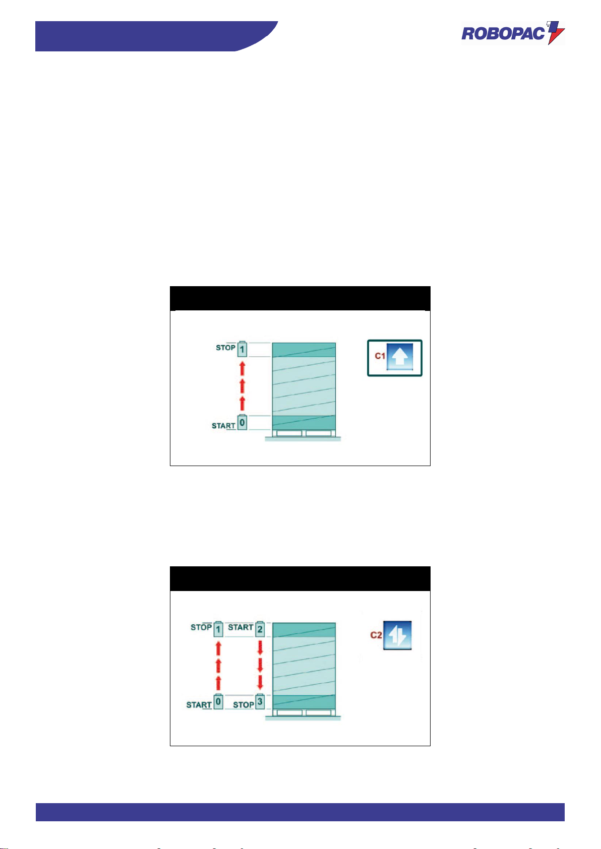
97
INFORMATION ABOUT THE USE
ENG
6.17. CYCLE PARAMETERS SETTING
1. Switch on the machine (See “Machine switching on and off”).
2. Choose the recipe number.
3. Press the button of the parameter to be edited to display the current value.
4. Press the buttons + / -, or scroll with the cursor, to increase or decrease the value until the required one is
obtained (See “programming window”).
This value will be stored in the relevant program.
6.18. DESCRIPTION OF THE WRAPPING CYCLES
6.18.1. SINGLE WRAPPING CYCLE
To select the “single cycle”, press the button (C1) and check that the relevant LED turns on.
The spool carriage starts moving from the pallet base and stops when it reaches the upper end, after having
performed the required number of wrapping turns at the base and at the upper end of the pallet.
Press the “START” button again to perform a second single wrapping cycle which starts from the top and goes down
until reaching the pallet base.
(See Paragraph “Wrapping cycle page”).
Rotoplat LP 308-508-708
Rotoplat TP3 308-508-708
6.18.2. DOUBLE WRAPPING CYCLE
To select the “double cycle”, press the button (C2) and check that the relevant LED turns on.
The spool carriage starts moving from the pallet base, rises until reaching the upper end and moves down until
reaching the base, performing a double load wrapping.
(See Paragraph “Wrapping cycle page”).
Rotoplat LP 308-508-708
Rotoplat TP3 308-508-708
Page 98
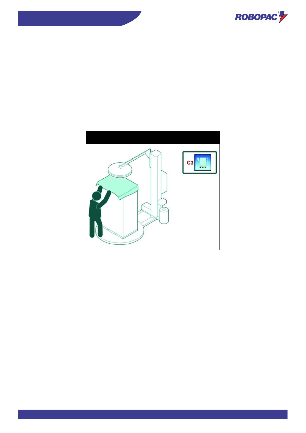
ENG
INFORMATION ABOUT THE USE
98
6.18.3. WRAPPING CYCLE WITH FEEDER
To select the cycle press the button (C3).
The machine performs a cycle aimed at making it easier for the operator to completely cover the pallet and ensuring
the higher possible level of protection.
The spool carriage rises until reaching the carriage upper end, moves down again by approximately 300 mm and
stops in this position.
If the machine features a presser, it rises from the load.
At this point, the operator, after placing the covering sheet onto the top of the pallet, activates the cycle again by
pressing the “START” button: the presser moves down again.
The carriage rises until reaching the pallet upper end, performs the programmed upper wrapping turns and moves
down to complete the cycle.
In this way, the position of the covering sheet, tightly bound to upward and downward film turns, is the most suitable
for ensuring an optimum protection of the load against external agents (water, dust, etc.).
Rotoplat LP 308-508-708
Rotoplat TP3 308-508-708
Page 99
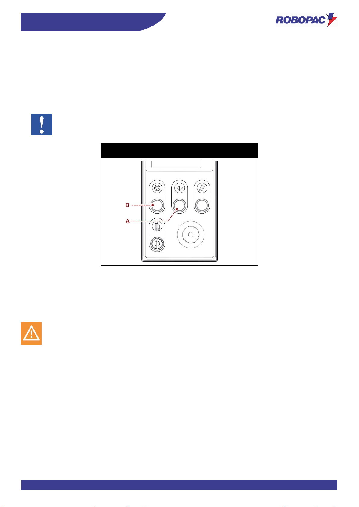
99
INFORMATION ABOUT THE USE
ENG
6.19. CYCLE START AND STOP
Proceed as follows.
1. Place the pallet on the rotary table and move the loading device away.
2. Fasten the film to the striker bracket (never to the gripper).
3. Press the "Cycle Start" button (A).
The machine completes the cycle and stops automatically.
4. Cut the film (If necessary).
5. Remove the pallet and position a new pallet to start a new cycle.
Important
To temporarily suspend the cycle, press the “Cycle stop” button (B).
Press the "Cycle Start" button (A) to restart it.
Rotoplat LP 308-508-708
Rotoplat TP3 308-508-708
6.20. PRESSER HEIGHT CHANGE
- Presser unit can be supplied with pneumatic (stroke 800) or mechanical cylinder version.
- The illustrations show the machine with the presser unit in the available versions.
- See tables to find the minimum height of the pallet to be wrapped in accordance with the version of the
presser installed on the machine.
Caution - warning
For “LP” versions, remove the load after the wrapping cycle
Page 100
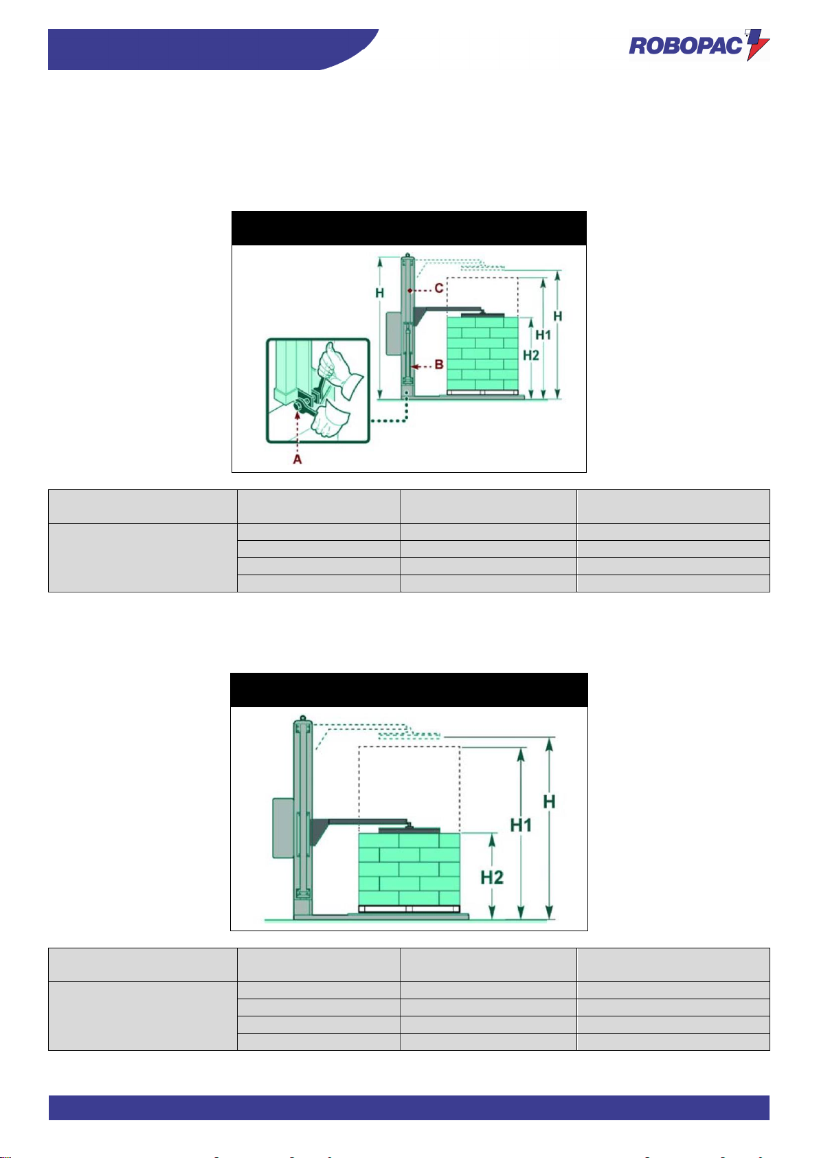
ENG
INFORMATION ABOUT THE USE
100
6.21. PNEUMATIC CYLINDER WITH ROD
1. Loosen the screw (A).
2. Adjust the height of the pneumatic cylinder (B) on the guide (C) according to the size of the product to be
wrapped.
3. Tighten the screw (A).
Rotoplat LP 308-508-708
Rotoplat TP3 308-508-708
Presser unit version
Slide shaft H (mm)
Arm in normal position
H1 (mm)
Arm in normal position H2
(mm)
Pneumatic cylinder with rod
2350
2200
1400
2550
2400
1400
2950
2800
1400
3250
3100
1400
6.21.1. MECHANICAL PRESSER
This presser does not need any adjustment for wrapping heights above 750 mm.
Rotoplat LP 308-508-708
Rotoplat TP3 308-508-708
Presser unit version
Slide shaft H (mm)
Arm in normal position
H1 (mm)
Arm in normal position H2
(mm)
Mechanical presser
2350
2200
750
2550
2400
750
2950
2800
750
3250
3100
750
 Loading...