

Page 1

Page 2
Original Operang Instrucons (EN)
Roboc Mower
RC304 / RC308 / RC312
MC400/MC800/MC1200
Operating Manual
Page 3

Table of Contents
Chapter 1 – Introduction And Safety ...................................................................................................... 3
1.1 Introduction .............................................................................................................................. 3
1.2 Warning Decal Denitions ........................................................................................................ 4
1.3 Safety Warnings & Precautions ............................................................................................... 4
1.4 Robomow Safety Features
Chapter 2 – Know Your Robomow® ........................................................................................................ 7
2.1 What’s in the Box ...................................................................................................................... 7
2.2 How Robomow Works For You ................................................................................................. 8
2.3 Robomow Features .................................................................................................................. 9
Chapter 3 – Planning Ahead ..................................................................................................................... 10
3.1 Lawn Types: What does your lawn look like ............................................................................. 10
3.2 Select Base Station Location ................................................................................................... 12
3.3 Select Power Box Location ....................................................................................................... 14
3.4 Planning the Perimeter Wire’s Layout ...................................................................................... 14
Chapter 4 – Initial Setup ........................................................................................................................... 16
4.1 Preparations ............................................................................................................................ 16
4.2 Perimeter Wire Setup .............................................................................................................. 16
4.3 Perimeter Wire within the Working Area .................................................................................. 19
4.4 Fastening Perimeter Wire to the Ground ................................................................................. 22
4.5 Back at the Base Station – Completing the Perimeter Wire Setup .......................................... 23
4.6 Placement and connection of the Base Station ....................................................................... 24
4.7 Connecting the Power Box .......................................................................................................
4.8 Setup in None-Base Zone ........................................................................................................ 26
Chapter 5 – Preparing Robomow ............................................................................................................ 29
5.1 Adjust the Cutting Height ......................................................................................................... 29
5.2 One-time Setup (Step By Step ................................................................................................. 29
Chapter 6 – Operation ............................................................................................................................... 32
6.1 Automatic Operation ................................................................................................................ 32
6.2 Operating Panel ....................................................................................................................... 32
6.3 Manual Operation ..................................................................................................................... 33
6.4 Menu Options .......................................................................................................................... 34
6.5 Operation in a Non-Base Zone ................................................................................................. 39
Chapter 7 – Using the Power Box ...........................................................................................................
7.1 Power Box Alerts ......................................................................................................................
7.2 Turn the Buzzer On/Off ............................................................................................................
7.3 Enable/Disable the Automatic Operation ..................................................................................
Chapter 8 – Charging ...............................................................................................................................
8.1 Charging During the Season ....................................................................................................
8.2 Charging Out of Season ...........................................................................................................
Chapter 9 – Troubleshooting and User Messages ................................................................................
9.1 General Error Codes .................................................................................................................
9.2 Detailed Error Codes ................................................................................................................
9.3 User Messages .........................................................................................................................
9.4 Basic Troubleshooting ..............................................................................................................
Chapter 10 – Product Specication ........................................................................................................
Chapter 11 – Maintenance and Storage ..................................................................................................
11.1 General Instructions ...............................................................................................................
11.2 Battery Maintenance and Disposal ........................................................................................
11.3 Winter Storage and Service ...................................................................................................
11.4 Maintenance of the Mowing Deck ..........................................................................................
11.5 Maintenance of the Blade ...................................................................................................... 52
11.6 Splicing the Perimeter Wire ................................................................................................... 53
11.7 Maintenance of the Base Station Area ................................................................................... 53
11.8 Lightning storm ...................................................................................................................... 53
Chapter 12 – Accessories ........................................................................................................................ 54
Chapter 13 – Tips for maintaining your lawn ......................................................................................... 55
Warranty Card ........................................................................................................................................... 56
............................................................................................................
6
24
40
40
40
40
41
41
41
42
42
44
46
47
50
51
51
51
51
51
Page 4
EN
Chapter 1 –
Introduction And Safety
EC Declaration of Conformity
Manufacturer: F. Robotics Acquisitions Ltd.
Hatzabar St., Industrial Zone
P.O.Box 1412 Pardesiya,
42815 Israel
F. Robotics Acquisitions Ltd. declares under sole responsibility that the products identied above conform to the Directives
below:
- Machinery Directive 2006/42/EC
Standards referenced: EN ISO 12100:2010.
- EMC Directive 2004/108/EC
Standards referenced: EN 55014-1:2011. EN 55014-2:2008. EN 61000-3-2:2006. EN 61000-3-3:2008.
- Noise Directive 2000/14/EC
Standards referenced: BS EN ISO 3744:2010. ISO 11094:1991.
- RoHS Directive 2011/65/EU.
Technical le representative:
Mr. Gerome De Schutter Friendly Robotics BV.
Address: Expeditieweg 4-6, Andelst 6673 DV, Netherlands.
I hereby declare that the above product conforms to the requirements as specied above
The products covered by this Declaration
26 Volt Battery operated Robotic Lawn Mower model:
Robomow RC304/308/312 MC400/800/1200
Shai Abramson – Senior VP R&D
F. Robotics Acquisitions Ltd.
Israel
26 December 2015
1.1 Introducon
The products are manufactured by F. Robotics Acquisitions (Friendly Robotics).
© Friendly Robotics, 2015-A. All rights reserved. No part of this document may be photocopied, reproduced, electronically
transmitted or translated without the prior written consent of Friendly Robotics.
Product, product specications and this document are subject to change without notice. All other trademarks are
property of their respective owners.
Welcome to the world of home robotics with the Friendly Robotics Robomow!
Thank you for purchasing our product. We know that you will enjoy the extra free time you will have while using Robomow
to mow your lawn. When set up and used properly, Robomow will operate safely on your lawn and provide you with a
quality of cut matched by a few mowers of any kind. You will be impressed with your lawn’s appearance and best of all,
Robomow did it for you.
IMPORTANT!
The following pages contain important safety and operating instructions. Please read and follow all instructions
in this manual. Carefully read and review all safety instructions, warnings and cautions contained in this manual.
Failure to read and follow these instructions, warnings and cautionary statements may result in severe injury or
death to persons and pets or damage to personal property.
3
Page 5
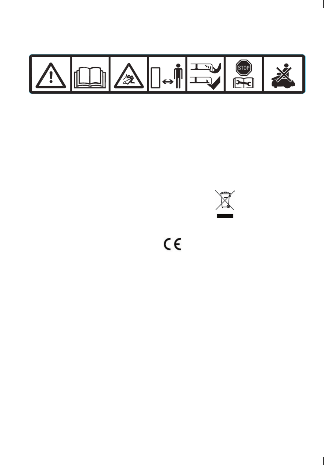
1.2 Warning Decal Denions
These are the symbols on Robomow®; Read about them carefully before operating Robomow®.
1 765432
1.
This is a dangerous power tool. Use care when operating and follow all safety instructions and warnings.
2.
Read the Operating & Safety Manual carefully before operating your Robomow®.
3.
Hazard of thrown objects during operation.
4.
Keep safe distance from Robomow® while operated. Keep people, especially children, pets and bystanders
away from the area where Robomow® is being operated.
5.
Risk of injury from Robomow cutting blades. Keep hands and feet away and do not lift Robomow® from the
ground.
6.
Activate the disabling device before working on or lifting Robomow® (see section 1.4)
7.
Do not ride on Robomow®.
Do not dispose Robomow
separately.
This product conforms to the applicable EU Directives
®
or any other part of it as unsorted municipal waste – It should be collected
1.3 Safety Warnings & Precauons
Training -
1.
Read this Operating and Safety Manual carefully before operating Robomow®. Be familiar with the controls and
the proper use of Robomow®.
2.
Never allow people who are unfamiliar with these instructions or children to use Robomow®.
3.
The user is responsible for accidents to other people or their property.
Preparation -
1.
Ensure the correct installation of the Perimeter Wire as instructed.
2.
Inspect Periodically the area where Robomow® is used and remove all stones, sticks, wires, , and other foreign
objects.
3.
Periodically visually inspect to see that the blade is not worn or damaged. Replace worn or damaged blade.
Operation -
1.
Do not operate Robomow® if any safety feature or any part is damaged, worn or inoperable.
2.
Keep hands and feet away from the cutting blade and other moving parts.
3.
Never pick up or carry Robomow® while the motors are running.
4.
Do not leave Robomow® to operate unattended if you know that there are pets, children or people in the vicinity.
5.
Never mow while people, especially children or pets are nearby.
6.
Always switch off the Safety Switch before lifting the mower or plan to operate any adjustments.
7.
Do not touch the blade before it is completely stopped rotating.
8.
Do not use Robomow® for any purpose other than cutting lawn.
9.
Keep all guards, shields, safety devices, and sensors in place. Repair or replace damaged parts, including decals.
4
Page 6

EN
Transportation –
To safely move from or within the working area:
1.
Press the STOP button to stop Robomow®.
2.
Use the Remote Control (available as an accessory) to drive it from one place to another.
3.
In case of different ground height level, switch off the Safety Switch, and carry the mower
by its carrying handle.
IMPORTANT! It is recommended to keep the original packaging for shipping purposes..
4.
When transporting Robomow® over long distances switch off the Safety Switch.
IMPORTANT! After turning on the Safety Switch, always re-set the current day and
time, otherwise unexpected operation of the Robomow may occur.
Using Remote Control (Manual Mowing)
1.
Mow only in daylight or in a good articial light and avoid operating on wet grass.
2.
Do not operate Robomow® when barefoot or wearing open sandals. Always wear substantial footwear and
long trousers; always make sure of your footing on slopes.
3.
Use extreme caution when reversing direction the mower towards you.
4.
Always switch on the motor according to instructions while standing away from the blade.
5.
Do not mow manually in slope greater than 15 degrees or where a rm footing is not possible.
Maintenance and Special Instructions–
1.
Always switch off the Safety Switch of Robomow® before clearing blockage/ checking/ cleaning/ working on
Robomow® or replacing the blade. Never attempt to service or adjust the mower while it is in operation.
2.
In case of abnormal vibrations, stop the mower, switch off the Safety Switch and check for any damage of the
blade. Replace worn or damaged blade to preserve balance. If vibration continues, call for service.
3.
Use heavy gloves when inspecting or servicing the blade.
4.
Do not perform maintenance when barefoot or wearing open sandals. Always wear suitable work shoes and long
trousers;
5.
Replace worn or damaged parts for your safety.
6.
Use only original equipment and accessories. It is not permitted to modify the original design of Robomow®. All
modications are made at your own risk.
7.
Maintenance/ Servicing / Cleaning of Robomow® should be according to manufacturer’s instructions.
8.
Keep all nuts, bolts and screws tight to be sure the machine is in safe working condition.
9.
Warning! When there is a risk of a lightning storm, disconnect the Perimeter Wire from the Base Station / Perimeter
Switch, and the Power Box 230V/120V plug from the power outlet.
Batteries –
1.
Do not open or damage the battery pack.
2.
The battery pack should be replaced only by a service dealer.
3.
The Battery Pack contains electrolytes. In case of an electrolyte leakage from the battery pack, the following
actions should be taken:
- Skin contact: Wash the contact areas off immediately with water and soap.
- Eye contact: Flush the eyes with plenty of clean water for at least 15 minutes immediately, without rubbing.
- Get medical treatment.
4.
Ensure that the battery pack is charged using the correct charger recommended by the manufacturer. Incorrect
use may result in electric shock, overheating or leakage of corrosive liquid from the battery.
Product End of Use -
1.
Robomow and its accessories should be collected separately at the end of their life to prevent waste electrical and
electronic equipment from ending up in landll sites, to promote the reuse, treatment and recovery of electrical and
electronic equipment with the purpose to preserve, protect and improve the quality of the environment, protect human
health and utilize natural resources prudently and rationally.
2.
Do not dispose of Robomow or any other part of it (including the Power Box, Base Station and Perimeter Switch) as
unsorted municipal waste – it should be collected separately.
3.
Ask your local distributor/dealer about return and collection systems availablity.
4.
Do not dispose the battery pack in a re, and do not place used batteries in your household trash.
5.
The battery must be collected, recycled, or disposed of in an environmentally sound manner.
5
Page 7

1.4 Robomow Safety Features
1.
Child Lock
The Child Lock prevents unintended operation of Robomow® by an accidental press of one of the buttons. Only
pressing two buttons in the right order will initiate the operation.
2.
Anti-Theft / Disabling Device
The Anti-Theft / Disabling Device system function will prevent anyone from using or driving the Robomow® unless they
have the valid code to enter. You will be prompted to enter a four digit code of your choice to use as your personal
security code.
3.
Lift Sensor
In case the mower is raised from the ground during blade operation, the blade will stop rotating immediately.
4.
Tilt Sensor
In case the mower is tilted up towards a vertical position, the blade will stop immediately.
5.
Obstruction Sensor
Robomow detects interfering obstacles in its way during operation. When the mower collides with an obstacle, the
mower will stop the rotation of the blade immediately, will stop movement in that direction and reverse itself away from
the obstacle.
6.
Emergency Stop Button
Pressing the STOP button at any time during operation will stop the mower and the blade immediately.
7.
Safety Switch
Switching off the Safety Switch will prevent any operation of Robomow®. It is required to switch it off before lifting
Robomow® and before any maintenance is done.
8.
Sealed Batteries
The batteries that operate Robomow® are completely sealed and will not leak any type of uids, regardless of its
position.
9.
Base Station / Perimeter Switch and Perimeter Wire
Robomow® cannot operate without a Perimeter Wire installed and activated through the Base Station / Perimeter
Switch. In the event the Perimeter Switch is turned off or otherwise fails to function, Robomow® will stop operating.
6
Page 8
EN
Chapter 2 –
Operating & Safety Manual
Know Your Robomow®
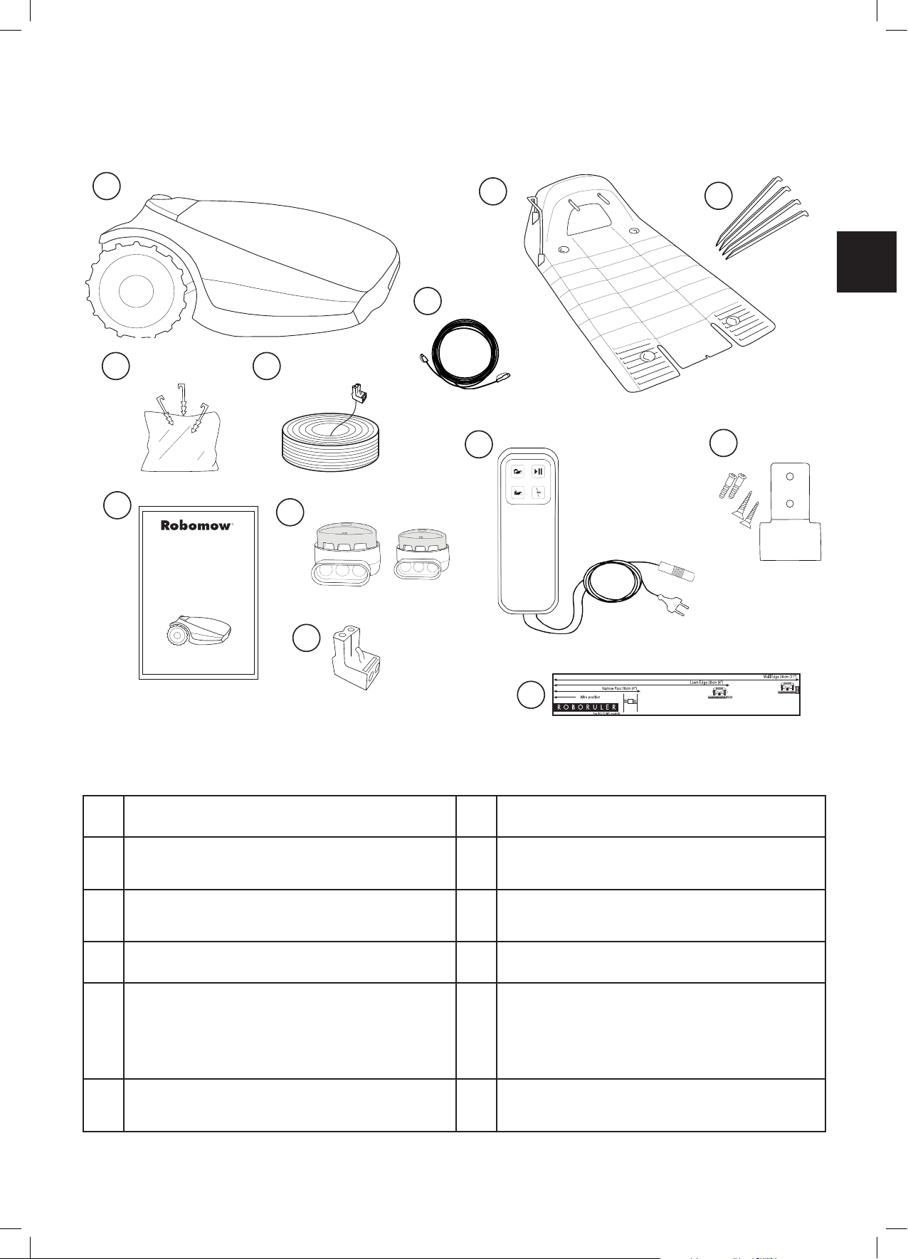
2.1 What’s in the Box
1
8
9
10
2
4
3
11
12
5
6
1 Robomow® 7
Wire Pegs Used for securing the wire to the
2
ground.
Perimeter Wire Used to create a virtual wall for
3
your Robomow.
4 Operating & Safety Manual 10
Wire Connectors Used for splicing wires (as
5
needed)
Plot Connectors Used for connecting the
6
Perimeter Wire to the Base Station.
11
12
7
RoboRuler Used for measuring the distance of
the Perimeter Wire from the lawn edge.
Base Station Used by Robomow to dock and
8
charge when it is not mowing.
Base Station Stakes Used for securing the Base
9
Station to the ground
Extension Cable 15 meters (50 ft.), (Low voltage
cable)
Power Box
The primary purpose of the Power Box is power
supply for charging Robomow.
Used to deactivate (halt) the automatic
operation mode and reactivate it as needed.
Power Box Mount Used for xing the Power Box
to a wall (including Screws and dowels).
7
Page 9
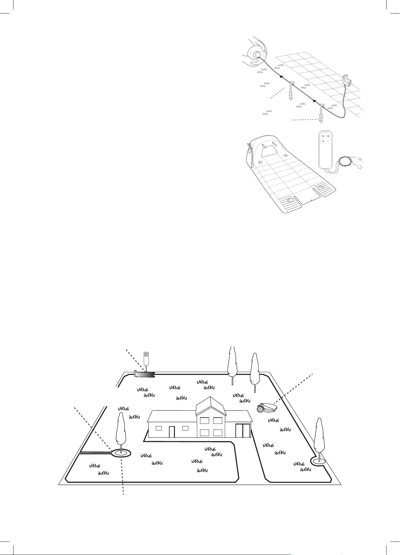
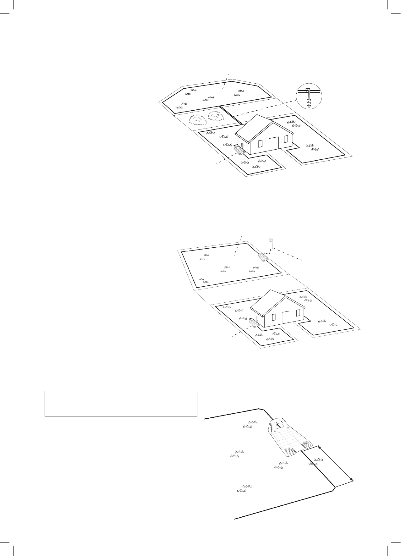
2.2 How Robomow Works for You
• First, you need to install a perimeter wire around the entire lawn
and around protected areas within the lawn area.
• The Perimeter Wire sets the boundaries for Robomow. The
Perimeter Wire is laid on the edges of the lawn and around
trees, plants, ponds and objects that you want to prevent
Robomow to run into.
• If the supplied wire is not sufcient, more wire can be purchased
and spliced to the existing wire with a supplied connector.
• Small pegs are used to fasten the Perimeter Wire into the
ground, below grass level.
• The Perimeter Wire will gradually disappear under the growth
of new grass until it will be invisible.
• The Base Station is placed along the Perimeter Wire. It performs
two basic functions:
- Generate a signal along the Perimeter Wire.
- Charge Robomow’s batteries.
• The Power Box is connected between the Base Station and a
230V / 120V wall socket, using a 15m (50 ft.) long low voltage
cable.
Perimiter Wire
Peg
• After completed the installation of the Perimeter Wire, Base Station, and the Power Box, and performing the
One-Time Setup (needs to be performed before operating Robomow for the rst time – detailed instructions
are in the following chapters), Robomow will do all the mowing for you for during the entire season!
• Robomow is a robotic lawn mower powered by a rechargable battery. It leaves its Base Station at scheduled
mowing times. Robomow mows the lawn and then drives back to the Base Station to be charged and ready for
its next scheduled mowing.
• As soon as Robomow departs for mowing, the Base Station automatically triggers a special signal by the
Perimeter Wire. This signal creates a virtual wall, visible only to Robomow. This signal keeps Robomow within
the lawn boundaries, and prevents it from entering areas it was intended to skip or protect.
• In order to prevent lawn’s damage at the Base Station area and in order to improve lawn’s coverage, Robomow
will drive from the Base Station at a random distance (between 90cm to 120cm) and will randomly select an
angle of departure between 40 to 90 degrees.
Base Station and Power Box:
- Generates signal along the wire.
- Charges Robomow’s battery.
Perimiter wire as a virtual
wall, visible only to Ro-
bomow
Large trees: Robomow is allowed to bump into
them. at this size the objects do not require a
Perimiter Wire around them
Robomow detects the
signal and changes
direction as it reaches
the wire
Tree surrounded by a groove, ditch or ower beds requires
a qire around it.
8
Page 10
EN
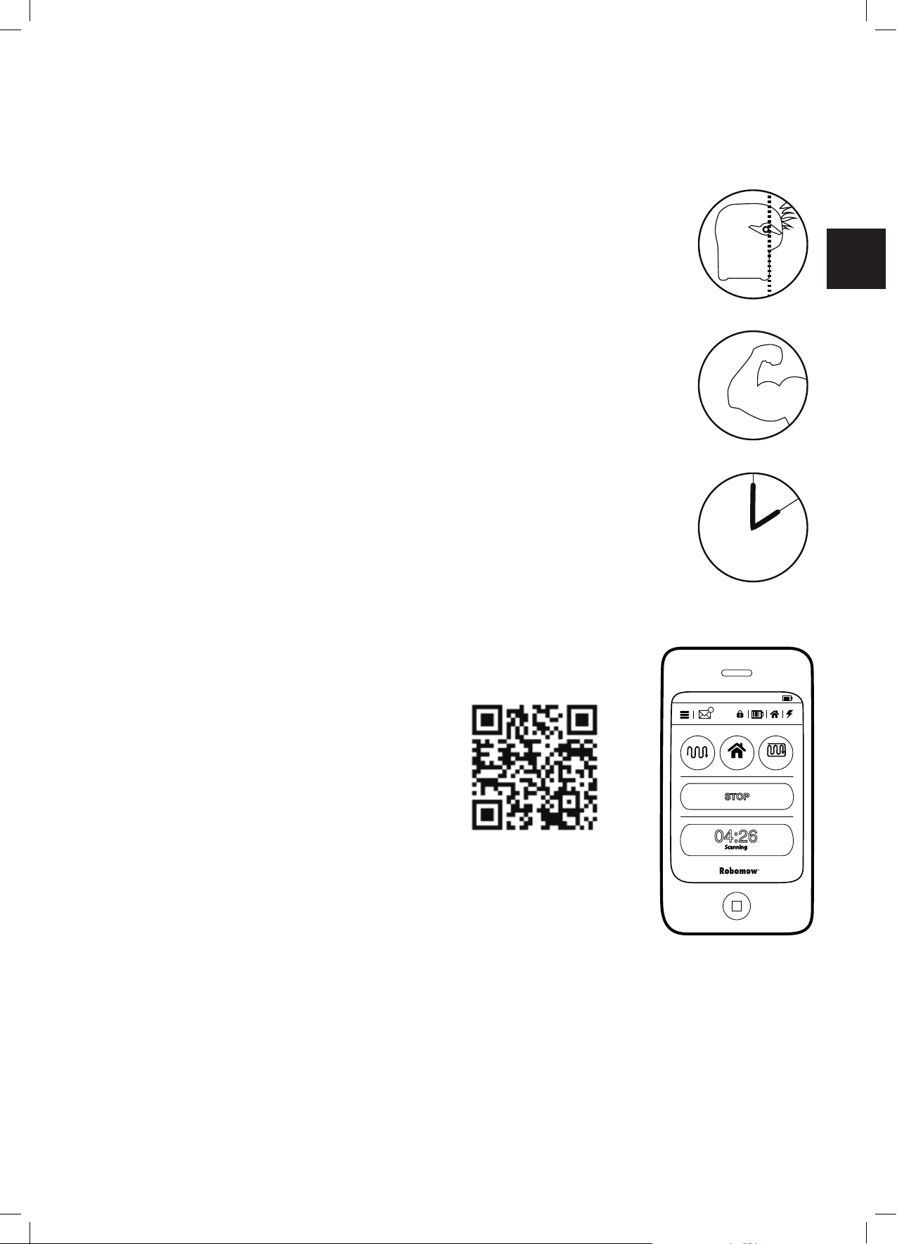
2.3 Robomow Features
SCAN HOME
EDGE &
SCAN
STOP
04:26
Scanning
3G 9:41 AM
100%
12
• Simple One-Time Setup – Robomow requires a simple one time setup, which can easily be done by the
consumer. Robomow recognizes the wire using special sensors, and makes sure it always stays inside the
designated area. Essential accessories are supplied with the product.
• Edge Cutting – Unlike other robotic lawn mowers, Robomow is the only robotic mower
that has a special Edge mode, in which it follows the perimeter wire for complete
coverage of the lawn edges. Robomow is the only robotic mower to cut outside the
wheels.
• Strong Cutting System – Robomow’s extra sharp blade enables to perform the rst
cut of the season, when the grass is relatively high.
• TurboMow Mode – TurboMow feature allows faster and stronger mowing of a high
grass during the rst cut of the season (see P026 in Section 6.4.2 for more information).
• SmartMow Mode – SmartMow feature allows more efcient mowing operation through
smooth and continuous turns at lawn’s edge (see P024 in Section 6.4.2 for more
information).
• Availability – The mowing width of Robomow (28cm / 11”) and the powerful cutting
system help Robomow to nish the job very fast and leave your lawn free for the family
to enjoy.
• A Remote Control is available as an accessory and is used for driving Robomow to
a separated zone, if necessary. It is also used for mowing small patches of lawn that
cannot be reached in automatic operation.
• Grasscycling – Robomow cuts the grass into very small clippings that are buried in
the roots of the lawn, where they decompose and act like a natural fertilizer. Grass
clippings contain 80-85% water and release valuable nutrients that return back into the
soil. It is the natural recycling of grass.
• Robomow App – A mobile application (available for Android and iOS), which enables
user friendly and intuitive operation of your Robomow, and opens additional menu
options and features.
For compatibility information of Robomow App please visit Robomow webpage.
To download the Robomow App, use
your mobile device to scan the QR code
on the left, or simply search for it in the
App Store or Google Play Store.
MORE TIME
TO ENJOY
9
Page 11
Chapter 3 –
At least 3 meters
Getting your lawn ready for Robomow is rather simple. As every lawn is unique, we recommend
reading this chapter before starting to install the perimeter wire. Planning the wire route and
drawing a sketch of the lawn, including all obstacles and Base Station location, will make it easier
and will prevent mistakes during the setup.
Please complete reading this “Planning Ahead” chapter before you start the setup. It will guide you in
nding the best locations for the Base Station, Power Box, and for the Perimeter Wire.
The Perimeter Wire functions is an “invisible wall” for Robomow. It sets the boundaries of lawn zones by
surrounding specic areas, as borders for the Robomow mowing. The Perimeter Wire is held to the ground by
small pegs, supplied with Robomow.
After set, the wire will becomes invisible under the growth of new grass. As soon as Robomow starts operating
a signal that runs along the Perimeter Wire keeps Robomow within its working zones and away from preset
demarcated areas.
Planning Ahead
Scan and watch Robomow setup & operation video.
Also available on Robomow website.
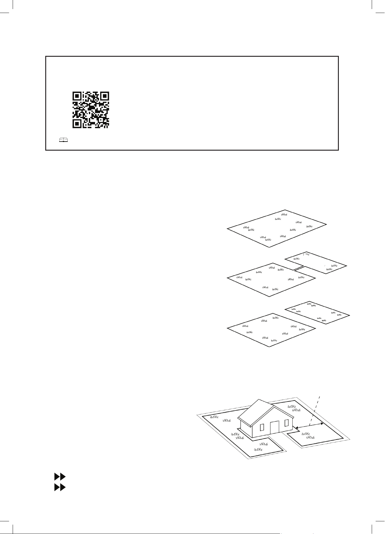
3.1 Lawn Types: What does your lawn look like?
There are 3 basic types of lawns: Some lawns are combinations of
more than one type.
Your rst task is to determine which type is yours.
o Main Zone Only
Robomow will simply mow this lawn within its set boundaries.
o Main Zone + Sub-Zone(s)
Robomow will mow the Main Zone and will move automatically
to the Sub-Zone(s).
o Separated Zone
Robomow will mow each zone separately. Its movement
between zones is restricted. Thus, you will have to bring the
mower from the Main Zone to the Separated Zone every time
you want to mow it.
3.1.1 “Main Zone Only” Type Lawn
The “Main Zone Only” lawn consists of one whole area.
It has no Sub-Zones and no Separated Zones.
If you answer “yes” to all of the following questions,
your lawn is a “Main Zone Only” type lawn:
o Is your grass area one continuous zone?
o Are all areas of your lawn wide enough for
Robomow to navigate through effectively? (Min.
3 meters (10 ft.) wide at its narrowest point).
Main Zone
Sub Zone
Main Zone
Separated-Zone
Main Zone
(10 ft.) wide
Main Zone Only
10
If your lawn does not match this description, read the next Sections to nd the style of your lawn.
If your lawn is “Main Zone Only”, you can skip to Section 3.3 of this chapter to determine the Base Station
location.
Page 12
EN
3.1.2 “Main Zone + Sub-Zone(s)“ Type Lawn
This type of lawn consists of more than
one zone, where zones are connected by
a narrow pass.
Sub-Zone
In this type of lawn, Robomow will be able
to drive from one zone to the other in order
to mow the whole area.
If you answer “yes” to all of the following
questions, your lawn is a “Main Zone + Sub-
Main Zone
Main Zone
Zone” type lawn:
Main + Sub-Zone with a Narrow Pass
o Is your grass area one continuous area?
o Are parts of your lawn separated from the Main Zone?
o Is there a Narrow Pass of at least 1m (3.3 ft.) for Robomow to drive between these zones?
o Is this Narrow Pass rm, in one level and smooth (not stony, sandy or elevated)?
For example: grass area, sidewalk, rm path, solid ground.
Such additional areas are called Sub-Zones.
If your lawn contains a Sub-Zone as dened in this section, refer to Section 6.4.2 (Add Sub-Zone – number
p022 in the table).
Dening Sub-Zone(s) will enable Robomow to drive through the Narrow Pass in order to get to a Sub-Zone and
to mow both the Main Zone and its Sub-Zone(s) one zone at a time.
If your lawn does not match this description, skip to the next Section 3.1.3 of this chapter: “Separate Zones”.
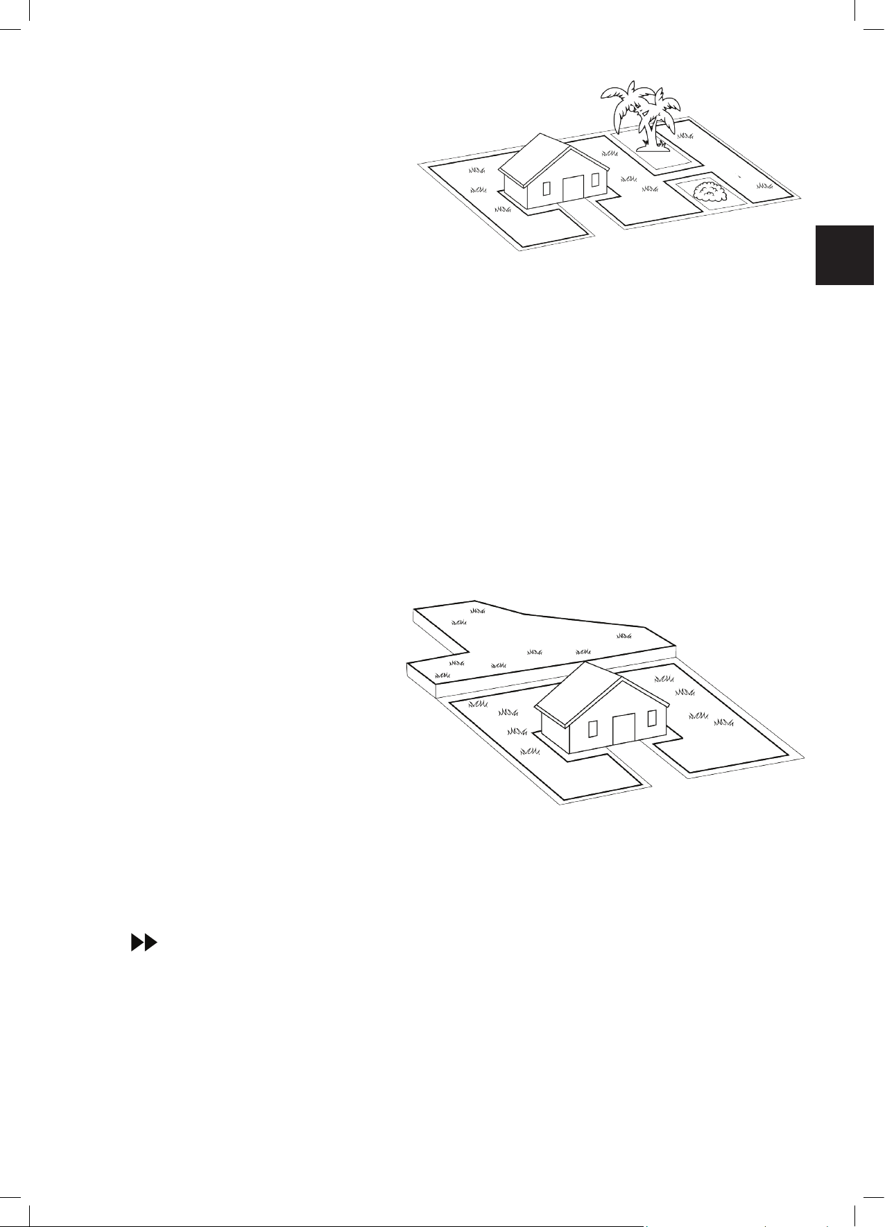
3.1.3 “Separated Zones” Type Lawn
“Separated Zones” type lawn consists of two or more zones that are not connected. Robomow cannot drive
between these zones.
If you answer “yes” to at least one of the following questions, your lawn is of the “Separated Zones” type.
o Are parts of your lawn separated by
fences, sidewalks, or other objects
that Robomow cannot pass?
Or
o Are parts of your lawn separated by
a gravel path or similar material that
may damage the mower blade?
Or
o Are the zones of your lawns joined
by a pass that is too narrow for
Robomow to drive through: less
than 1m (3.3 ft.) in width?
Or
o Are the zones of your lawn situated at lower or higher level?
If your lawn contains a Separated Zone as dened in this section, refer to Section 6.4.2 (Add Separated
Zone - number p014 in the table).
Separated Zone
Separated Zone
Main Zone
Main Zone
Main Zone
Main Zone
Separated Zone
Separated Zone
If your lawn does not t any of these descriptions, it is probably either a “Main Zone Only” or
“Main Zone +Sub- Zone” type. Skip to Section 3.3 – Select Base Station and Power Box Location
A lawn may consist of up to 2 Separated Zones
.
The mower must be carried or driven to this area manually.
Any of the 3 types can be a combination of more than one type of lawn.
.
11
Page 13
3.1.4 Types of Separated Zone
Min. 3m (10ft) from any
setups:
A Separated Zone smaller than 100 m² (1100 ft²)
o Separated area that is smaller
than 100m² (1100 ft²) can be
covered in a single operation,
thus, if possible, the separated
area may be connected to the
main area’s Perimeter Wire
(have the signal come from the
Main Base Station).
Or
o It may need its own separate
Perimeter Wire.
In that case, it will have to
be connected to a Perimeter
Switch (optional accessory –
see Chapter 12 – Accessories).
Or:
Base Station
A Separated Zone larger than 100 m² (1100 ft²)
o If a separated area is larger than
100m² (1100 ft²), then it requires
more than a single operation to
cover the area;
o In such case, an additional Base
Station (optional accessory)
should be installed in the
Separated Zone; otherwise
you will have to manually bring
the mower several times to the
Separated Zone, in order to
complete the mowing of the area..
Separated Zone Smaller than 100m² (1100ft²)
2 Wires under
same peg
Separated Zone larger than 100m² (1100ft²)
Optional Power Box &
Base Station
3.2 Select Base Staon Locaon
3.2.1 Base Station Location Guidelines
Do not place the Base Station within 3 meters (10
ft.) after a corner (relevant for Internal Setup only
– section 3.2.2)
The Base Station should be within 15m (50 ft.)
distance from a power outlet (230V / 120V).
If the lawn has more than one zone, place the Base
Station within the largest zone.
Make the Base Station invisible to the street to
avoid theft.
Select a shady spot. This will extend battery lifetime.
Place the Base Station on a relatively level ground.
Do not place it on a slope.
Place the Base Station away from sprinkler heads.
Main zone Power Box &
Base Station
corner
12
Page 14
EN
There are two options to set the Base Station:
3.2.2 Internal Setup (on the lawn perimeter)
• Choose a place along the Perimeter Wire where
you want to place the Base Station, based on the
onditions detailed in paragraph 3.2.1.
• Place the Base Station in the direction shown in the
gure to the right.
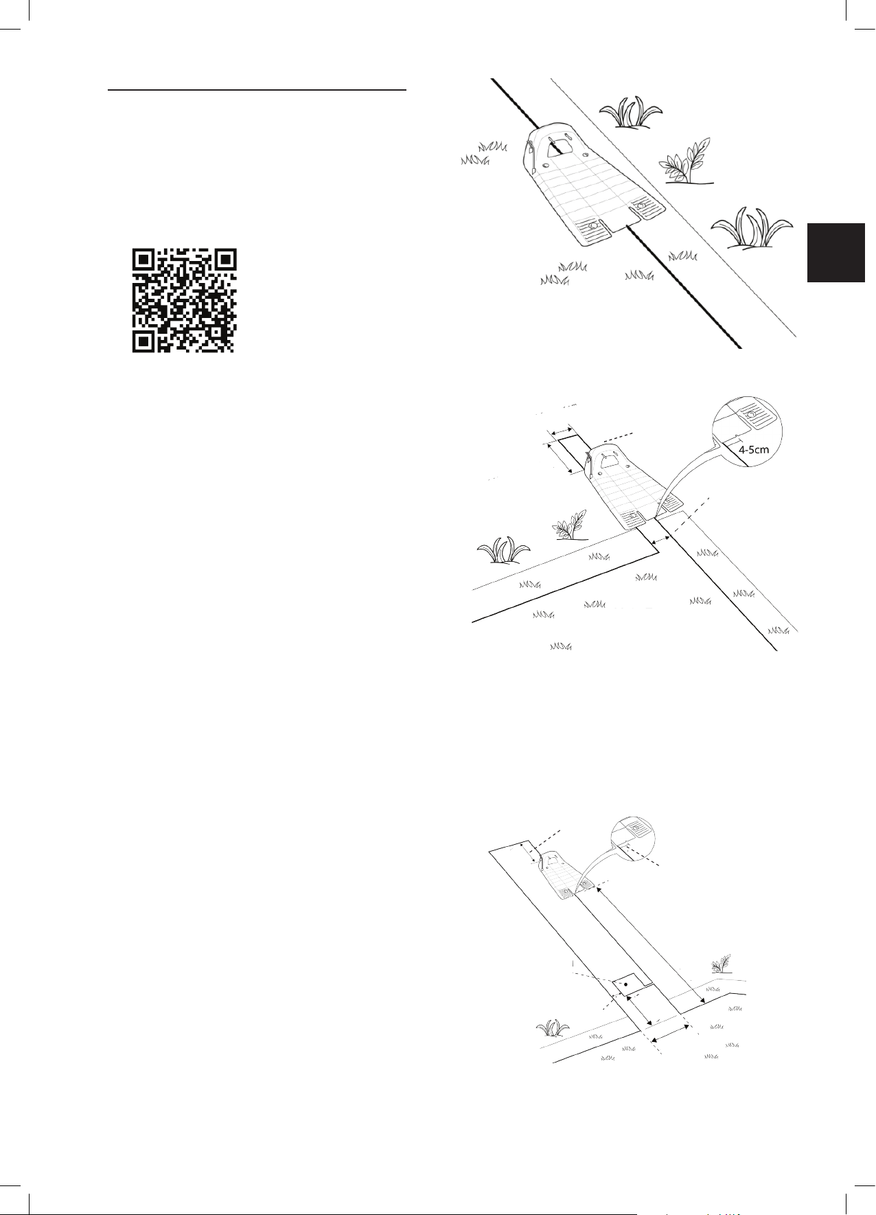
3.2.3 External Setup (off the lawn perimeter):
Scan the code to watch the
video on how to install an
external base.
There are two types of External Setup:
A.
At a corner
In this type of setup, the Base Station is located at one of
10cm (4”)
the corners of the lawn, as shown in the gure at the right.
• Choose a corner where you want to place the Base
Station outside of the lawn area.
• Place the Base Station, where its front side is touching
Min. 10cm (4”)
10cm (4”)
the lawn edge or placed somewhere on the lawn.
• Continue to lay the perimeter wire as shown in the gure
on the right, where it continues at least 10cm (4”) beyond
the Base Station and turns back towards the lawn at a
distance of 10cm (4”) from the other wire.
• The Base Station may be placed in a small shift to the
right, in order to allow smooth entry of the mower to the
Main Zone
Base Station.
• Later you will have the opportunity to adjust the Base
Station position to conrm smooth entry.
B.
Outside the lawn
(Can be set only through the Robomow App for specic models)
• Choose a place outside the lawn where you want Robomow to dock and charge.
• Conrm the path between the lawn and the outside area is smooth with no height difference, so Robomow will
not get stuck and will follow the wire smoothly.
• The surface between the lawn and the Base Station should be hard (such as a sidewalk or rigid ground) and
not sandy or stony, so Robomow will not slip or get
stuck on it.
Min. 10cm (4”)
• The area between the lawn and the Base Station
should be clear of obstacles and objects.
5-4cm
• Lay the wire as shown in the gure to the right:
- Narrow path of 50cm (20”) width.
Min 1.8m (6ft)
Max 4m (13ft)
- Square Perimeter Island of 30cm (12”) edges.
- Island starts 50cm from the Perimeter Wire.
- Keep a distance of 10cm (4”) between Perimeter Wire
and the Island from both sides.
- The front of the Base Station should be placed a
minimum distance of 1.8m (6 ft.) from the Perimeter
Wire and NOT more than 4m (13 ft.).
Perimeter
Island 30cm
10cm (4”)
(20”)
50cm
50cm
(20”)
13
Page 15
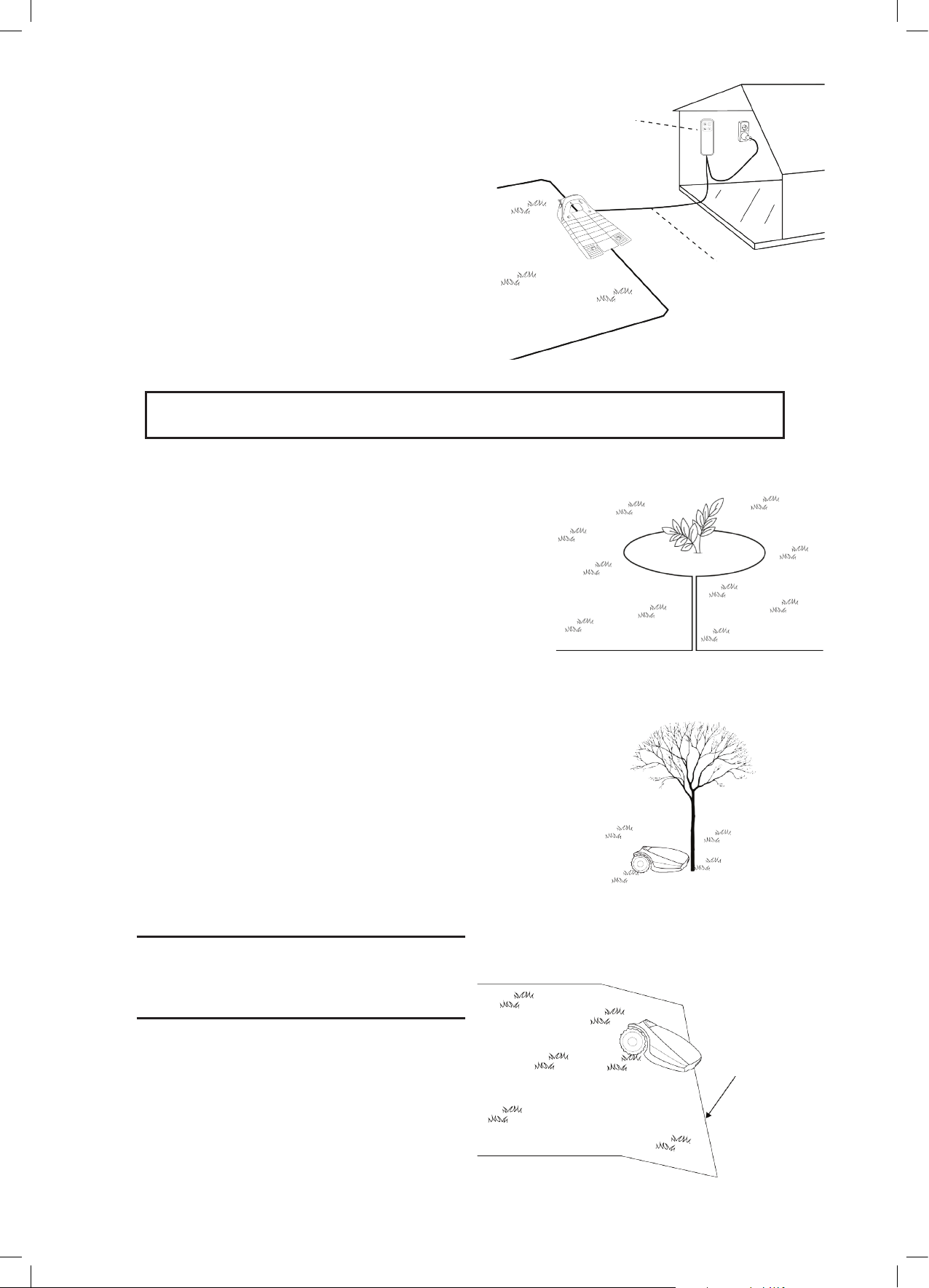
3.3 Select Power Box Locaon
Consider the following in order to select the Power Box
location:
The Power Box will be connected to the Base
Station using the 15m (50ft.) Extension Cable.
Select a suitable location for the Power Box to be
mounted on a wall near a power outlet.
Locate it outside the lawn perimeter.
Select an easily accessed spot.
Select a dry and sheltered location.
The Power Box is to be mounted vertically.
The Power Box is suitable for Outdoor use. Yet, it should be placed in a sheltered, dry
and well ventilated spot. The Power Box should not be exposed to direct sunlight or rain.
3.4 Planning the Perimeter Wire Layout
3.4.1
Objects inside
lawn
Power Box xed to
the wall
15m (50ft) Extension
Cable (low voltage)
Objects such as ower beds, ponds, or small trees can
be protected by creating “Perimeter Islands”, which
are demarcated areas of the lawn, where Robomow
should not enter.
In the areas where obstacles are grouped closely
together, they should be demarcated by a single,
continuous Perimeter Island.
Obstacles that are vertical, relatively rigid, and higher
than 15 cm (6 inches), such as trees, phone or power
poles, do not need Perimeter Island. Robomow will
turn when it collides with these obstacles.
3.4.2
Slopes
Slope on the perimeter
The Perimeter Wire can be laid across a slope
that slants less than 10% (10cm rise per 1m).
CAUTION! If the Perimeter Wire is laid across
a slope steeper than 10%, there is a risk that
the mower will slip and cross outside the wire,
especially when the grass is wet’.
14
However, if there is a barrier (e.g. fence or wall)
that can protect the mower from slipping off, the
Perimeter Wire can be set on that slope.
Perimeter Slope
Max. 10%
Page 16
EN
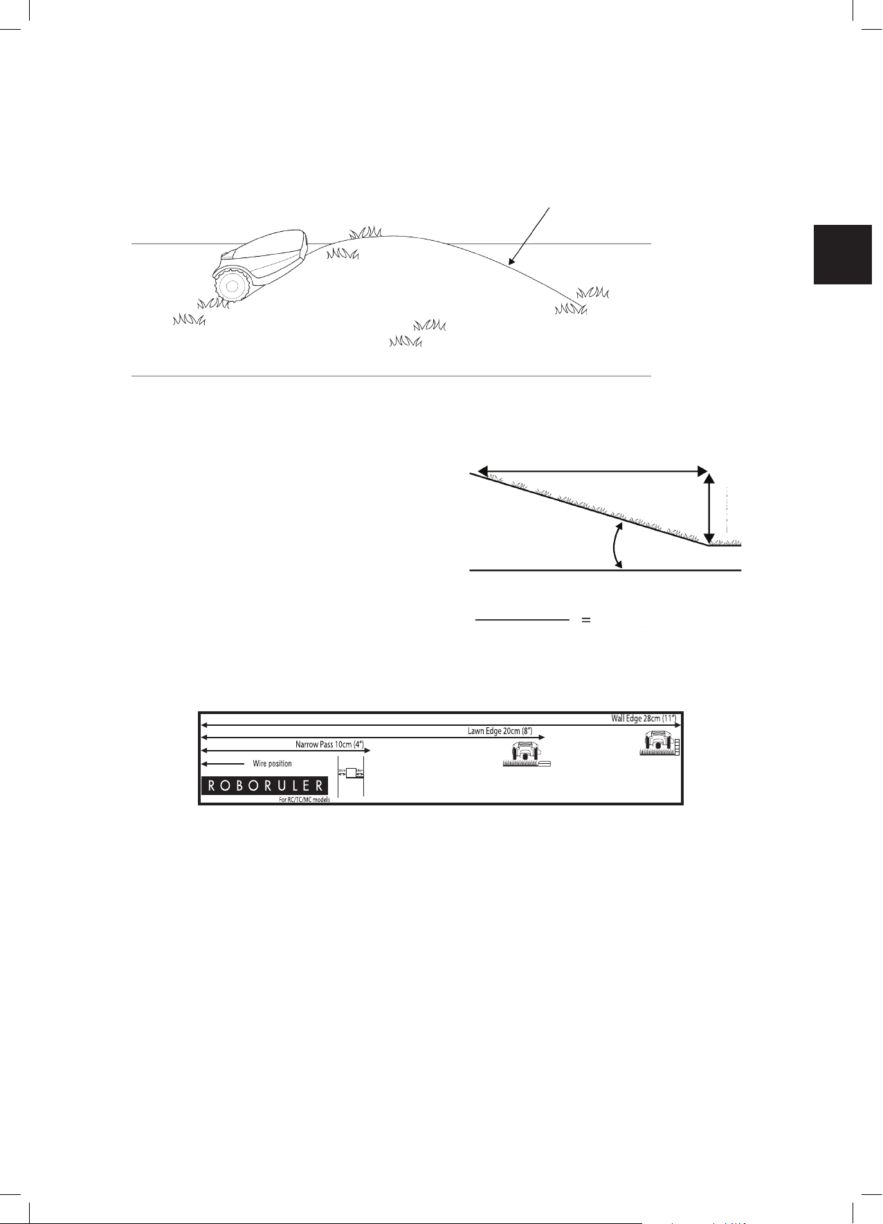
Slope inside the lawn
Robomow can mow areas inside the working area with a slope of up to 35% (35cm rise per 1m).
Tip: If the mower tilts off the ground while climbing a slope, it is too steep. Exclude this steep area from
Robomow’s cutting area.
In Lawn Slope 35%
How to calculate the slope of your lawn?
100cm (3.3ft)
Length
35cm (1.1ft)
Max 35% slope
How to calculate the slope of your lawn?
35cm (Elevation)
100cm (Length)
3.4.3
Distances from the Edge (Pools, Ponds, Cliffs, etc.)
RoboRuler is used to measure the distance from the edge, where the wire is to be placed.
In certain cases, near bodies of water such as pools and ponds, or great height differences such as cliffs, it is
required to maintain a greater distance from the Edge (see Section 4.2.2).
3.4.4
Interference with adjacent lawns
In case there is another robotic mower (from the same or different manufacturer) working in an adjacent lawn,
you need to keep at least 3 meters distance (10 ft.) from the perimeter wire of that lawn.
35% (slope)
Elevation
15
Page 17
Chapter 4 –
Initial Setup
4.1 Preparaons
Recommendations before you start
During setup, you need to insert pegs into the ground. To
complete this task smoothly, we recommend not to do it while
the grass is high and to water it before starting.
4.1.1 Getting Ready
Make sure all parts needed for setup are within your reach.
Have the Robomow box nearby, so all items are available.
In addition, you will need the following tools: A hammer, small
at screwdriver, Phillips screwdriver, Combination Pliers.
4.1.2 Installing the Power Box
Mount the metal bracket onto a vertical surface with the
provided screws. Make sure the narrow part with the holes
facing up as shown in the gure to the right.
• Place the Power Box above the metal bracket and slide
it into place along the vertical surface.
• Connect the Power Box to a regular power outlet (230V
/ 120V).
Hammer Combination Piers
Small at and Philips
Screwdrivers
4.1.3 Charging the battery before the rst operation
You can charge the Robomow battery while running the setup
of the Perimeter Wire. This will ensure that Robomow will be
ready for operation when the setup is completed.
• The power of the mower is switched off when shipped
from the factory. Switch on the Safety Switch to power
on the mower.
• Connect the DC Cable coming from the Power Box to the
Charging Socket at the rear side of Robomow.
• Conrm the Battery LED on Robomow is blinking, which
is an indication of charging.
• Leave Robomow connected to the Power Box while
completing the setup of the Perimeter Wire.
Note!
Your product comes with a minimal battery charge, which
is only sufcient for performing the One-Time Setup. This
initial charge does not allow performing a complete mowing
operation
Safety Switch
4.2 Perimeter Wire Setup
Before you start the setup, you should have a plan for the Perimeter Wire layout and for the location of the Base
Station. Your plan should consider the following:
o What type of lawn areas does your lawn have?
(Main Zone Only / Main + Sub-Zones / Separated Zones / combination of types).
o Are there protected or excluded areas on the lawn? (Perimeter Islands).
o Are there any slopes that Robomow should avoid?
o Are there edges of pools, ponds, cliffs etc., which need an extra distance from the Perimeter Wire?
16
Page 18

EN
4.2.1 Starting Point: Perimeter Wire at the Base Station area.
• Place the Base Station, according to your plan, as shown in the
gure to the right.
Do not place the Base Station within 3m (10 ft.) after a corner
• Select the roll of wire with a green plot connector attached to
the end.
• Pull the plot connector and some wire out of the plastic covering.
Do not remove the spool of wire from its covering. The plastic
covering is the dispenser for the wire.
• Peg the beginning of the wire to the ground, where the Base
Station will be located. Pegs are supplied in the Robomow’s
box.
• Pull out 30 cm (12 inches) of wire and leave it loose near the
Base Station location. Later, at the end of the setup, this part of
the wire will close the Perimeter Wire loop.
• Start laying the wire in an anticlockwise direction.
• Continue to pull the Perimeter Wire out of its covering, laying it
loosely as you walk along the lawn edge.
Perimeter Wire
Min. 3m (10 ft)
from any corner
Peg
If you get to any area/object that needs care or special boundaries, make sure you carefully lay the
Perimeter Wire as needed. The next sections deal with such special cases.
4.2.2 Laying the Perimeter Wire
o The Perimeter Wire is secured to the ground by pegs
supplied with Robomow. Initially insert pegs every
few meters and at corners. At this early stage set a
minimum number of pegs. Later, after testing the wire
setup, you will insert all necessary pegs.
o After uncoiling some wire, before inserting pegs, use
the RoboRuler to determine the distance of the wire
from the lawn edge or obstacles.
• If the working area borders with a at area, a ower
bed, a small cliff (not more than 1 cm / 0.4”), or a
small stair (up to 5 cm / 2”), the Perimeter Wire
should be laid 20 cm (8 inches) inside the working
area. Use the shorter distance of the RoboRuler to
set the distance of the wire from the lawn edge.
20cm (8”)
• If the edge is going though a sloped area (max 10%
is allowed) or is bordered with high obstacles such
as a wall or fence, the Perimeter Wire should be laid
at a distance of 28 cm (11 inches) from the obstacle.
Use the longer distance of the RoboRuler to set the
distance of the wire from a wall.
28cm from Wall (11”)
17
Page 19

• If the working area borders against a at path
Min 1.2m ( 4ft )
Min 15cm ( 6’’ )
28cm (11’’ )
Perimeter Wire
90
o
45
o
that lies level with the lawn, it is possible to allow
Robomow to run over the path. The Perimeter Wire
should then be laid 10 cm (4 inches) from the edge
of the path.
• When the working area is divided by a at path
that is level with the lawn, it is possible to allow
Robomow to run over the path. The Perimeter Wire
can be laid under the pavement blocks or in the joint
between them.
Important!
The mower must never run over gravel, mulch, or
similar material, which can cause the mower to slip
and damage the blade.
IMPORTANT INFORMATION
If the working area is near a swimming pool,
watercourse, slope greater than 10%, precipice
higher than 50cm (20 inches) or a public road,
the Perimeter Wire must be supplemented with
a fence or alike. The height must then be at least
15cm (6 inches). This will prevent the mower from
ending up outside the working area under any
circumstances.
If such a barrier exists, you may set the Perimeter
Wire 28cm (11 inches) from the barrier.
If there is no fence or the like, then lay the
Perimeter Wire at minimum distance of 1.2m from
the water.
o Maintain a 45° angle in all left-turn corners when
laying the wire along the perimeter. It is not necessary
to maintain 45° angle on right-turn corners along the
perimeter.
Min 1.2m ( 4ft )
Perimiter Wire
Min 15cm (6”)
28cm (11”)
18
o Continue laying the wire, according to your plan.
Gradually pull the wire out of its dispenser and lay it
loosely as you are moving in an anticlockwise direction.
Right turns
20cm
Left turns
Page 20

EN
4.3 Perimeter Wire within the Working Area
Perimeter Wire Position
2 Wires under
same peg
Perimeter Wire
Direction of setup:
Clockwise around
obstacle
Min. distance between
islands: 1m (3.3ft).
Otherwise,demarcate
jointly as one island
28cm
28cm
Min 1m
4.3.1 Hard Obstacles
o Obstacles that can withstand a collision, for example, trees or bushes
higher than 15 cm (6”), do not need to be demarcated by the Perimeter
Wire. Robomow will turn when it collides with this type of obstacle.
4.3.2 Perimeter Islands
o Use the Perimeter Wire to demarcate areas inside the working area by creating islands around obstacles that
cannot withstand a collision, for example, ower beds and fountains.
o Continue uncoiling the wire, moving from the edge towards the protected object.
o Peg the Perimeter Wire around the protected object in a clockwise direction.
o Complete bordering the island and return to the spot where you left the lawn’s edge
o The wires leading to the Island and from it should be parallel and touching. Therefore, peg both wires, to and
from the island, together with the same pegs.
o Robomow will not recognize these two wires. It will mow over them as if they do not exist.
o Robomow will recognize the single blocking wire around the Perimeter Island and will not enter this area.
Perimiter Wire Position
2 Wires under
same peg
Perimiter Wire
Direction of setup:
Clockwise around
obstacle
CAUTION ! Setting the Perimeter Wire anticlockwise around an obstacle
will cause the mower to drive into the island.
Keep the following distances when setting Perimeter Islands:
- The minimum distance of the Perimeter Wire from
the protected area should be 28 cm (11 inches).
- If you need to protect a thin object, set the minimum
- Maintain a minimum of 1m (3.3 ft.) between adjacent
- Maintain a minimum of 1m (3.3 ft.) between island
- If protected objects are grouped closely together,
Note! A Perimeter Island should either be
rectangular or round.
radius of the Island to 35 cm (15 inches).
islands.
wire and the Perimeter Wire.
demarcate them as a single Perimeter Island.
Min. distance between
islands: 1m (3.3ft)
Otherwise, demarcate
jointly as one island
28 cm
28 cm
19
Page 21

4.3.3 Setting a Narrow Pass
A Narrow Pass is dened as a path that connects two zones of the lawn. The path enables Robomow to drive
between the zones while following the wire, but prevents the mower from crossing between them while mowing
the inner area of the zones. The pass has to be at least 1.2 m (4 ft.) wide to allow Robomow to drive through it.
If the pass is wider than 2 m (6.5 ft.),
There is NO need for any special setting of the Perimeter Wire. Skip to section 4.3.4. Otherwise, you need to follow
the instructions given below in order to set up a Narrow Pass.
Scan the code to view a video explaining how to
set a narrow pass
If the passage is NARROWER than 1.5m and longer then 2m,
the following wire installation needs to be done – “dual-square installation”:
1. Dene the entry to the Narrow Pass - the point you want the mower to start driving towards the Sub-Zone.
2. 50 cm (20 inches) from the Narrow Pass entry, set a Perimeter Island (refer to 4.3.2) as shown in the picture
above.
3. Continue to lay the wire along the edge at a proper distance (depending on the edge type) until coming back
to the Narrow Pass entry from the Sub-Zone side.
4. Measure 50cm (20 inches) from that point and lay another Perimeter Island with the same dimensions.
5. After completing the setup of the wire in the Sub-Zone, make sure you keep 10 cm (4 inches) between the wire
and the islands on the way back to the Main Zone.
10cm
28cm
Sub-Zone
Min. 50cm
50cm
Main-Zone
The above setup allows Robomow to drive along the wire to reach the Sub-Zone. However, while mowing each
zone individually, it will not cross over to the other zone.
50cm
2 Wires under
same peg
10cm
20
Page 22

EN
If the passage is WIDER than 1.5m:
If the Narrow Pass is wider than 1.5m (5 ft.), and you want Robomow to mow the area inside the Narrow Pass, then
you can set the wire as shown in the gure below. Such a setup allows the mower to mow inside the Narrow Pass
while mowing the inner part of the lawn, but prevents it from crossing between the zones.
1. Dene the entry to the Narrow Pass - the point you want the mower to start driving towards the Sub-Zone.
2. Set an Perimeter Island at the middle of the Narrow Pass (refer to 4.3.2) as shown in the picture above and
keep a distance of 10 cm (4 inches) from the Perimeter Wire.
3. The island dimensions should be 28 cm (11”) along the side and as wide as needed, when keeping 10 cm (4
inches) from both sides.
4. After completing the setup of the wire in the Sub-Zone, make sure you keep 10 cm (4 inches) between the wire
and the island on the way back to the Main Zone.
10cm
28cm
Main-Zone
Good VS Bad Narrow Pass:
The following drawing illustrates a good (at) vs bad (bumpy) narrow passage.
Min. 50cm
2 Wires under
same peg
Sub-Zone
10cm
Main Zone
Sub Zone
Main Zone
Sub Zone
21
Page 23

4.3.4 Using Sub-Zones as Remote Starting Points
There are cases when a Main Zone has two or more big parts connected by a wide (more than 2 meters) passage,
like a front and a back yards.
In order to ensure proper coverage of all Main Zone’s parts in such cases, you may want the mower to occasionally
start mowing at some specic point (other than the Base Station) along the perimeter wire. We call these points
– Remote Starting Points. Setting a Remote Starting Point can be done by dening (adding) a Sub-Zone at the
desired place (see section 6.4.2, P022-P023).
Note:
During the Sub-Zone denition process you are asked to specify the area of a newly added sub-zone. In case of
a Remote Starting Point, this area should be the area of the remote part of the Main Zone. You need to reduce
Main Zone’s area setting accordingly (see section 6.4.1). See the example below. This process actually denes
the probability (or the frequency) of departures from each starting point (when for the Main Zone the Base Station
itself is a starting point).
Example:
Let’s say your Main Zone is 1000m
has a back yard (400m2), where the
Base Station is installed, and a front yard
(600m2). In order to dene a Remote
Starting point for the front yard, start a
process of adding a Sub-Zone. Once
well inside the front yard, set the area of
the newly added Sub-Zone to 600 and
immediately reduce (see section 6.4.1)
the area of the Main Zone to 400m2.
Thus, we now have 40% probability for
the mower to start from the Base Station
to cover the back yard, 60% probability
to start from the Remote Starting point in
favor of the front yard, as demonstrated
in the following drawing:
2
. It
At least 2 meters (6.5 ft.)
wide
Main Zone
Remote Starting Point
4.4 Fastening Perimeter Wire to the
o Before starting to lay the Perimeter Wire, it is recommended to cut the grass where the wire is to be laid.
It will then be easier to attach the wire to the ground. The risk that the mower will damage the wire during
the operation is reduced.
o It is not necessary to bury the Perimeter Wire, though you may do so, up to 5 cm (2 inches) deep.
o Pull the wire tight while hammering the peg all the way into the ground.
o Consider burying the wire at exposed areas, such as pavements or other areas with a frequent foot trafc.
WARNING !
Protect your eyes! Protect your hands!
Use proper eye protection and wear appropriate work gloves when hammering the pegs.
Hard or dry ground may cause pegs to break when driving them in.
o Use a hammer to insert the pegs into the ground.
o Insert the pegs at distances that will keep the wire
down below the grass level and prevent the wire from
becoming a tripping hazard (approximately 75 cm /
30” between pegs).
• The wire and the pegs will gradually become
invisible under the growth of new grass.
Ground
22
Page 24

EN
o If an additional wire is required in order to complete
Small flat screwdriver
the setup, connect it using the water-proof wire
connectors supplied with Robomow. (See Section
11.6 – Splicing the Perimeter Wire).
Use only the wire connectors supplied with Robomow.
Neither Twisted cables, nor a screw terminal insulated
with insulation tape are a satisfactory splice.
Soil moisture may cause the conductors to oxidize, which
will later cause a broken circuit.
4.5 Back at the Base Station – Completing the Perimeter Wire Setup
Once the Perimeter Wire loop is completed and pegged to the
ground, complete the setup by attaching the beginning and the
end of the Perimeter Wire to the Base Station Head.
o Peg the two Perimeter Wires down to the ground using the
same peg leaving enough loose wire.
o Trim the end without the connector to make both of equal
length and twist the two wires.
o Twist the two wires. A proper twist of the wires is crucial for a
robust docking of Robomow at the Base Station.
o Strip back 5 mm (1/4 inches) of insulation from the wire end.
o Insert the end of the wire without the connector into the hole
of the connector. Use a small at screwdriver to tighten and
secure this wire into the connector.
Small at screwdriver
23
Page 25

4.6 Placement and connection of the Base Station
o Place the Base Station on the Perimeter Wire as shown
in the gure to the right.
o Align the center of the Base Station on the wire.
o Attach the Perimeter Wire connector to the Base Station
Head.
o After the Base Station has been positioned, insert 2
stakes into the Base Station holes as shown in the gure
to the right. Only after the Base Station position has
been tested during the One-Time Setup process (see
Section 5.2), you will be able to insert the remaining two
stakes.
4.7 Connecting the Power Box
In order to nd a proper location for the Power Box, please refer to Section 3.3.
For the Power Box installation instructions please refer to Section 4.1.2.
Laying and Fastening Extension Cable
Safety – Avoid injury!
The Extension Cable from the Power Box to the Base Station should
be securely fastened to the ground! It should never present a tripping
hazard.
24
The Extension Cable should cross ONLY over soft surfaces. It should
not cross over hard surfaces (e.g. Sidewalk, driveway) where it cannot
be securely fastened.
Page 26

EN
4.7.1 At the Power Box Location:
• Connect the DC Cable from the Power Box to
the 15 m (50 ft.) Extension Cable.
• Connect the Power Box to a regular power
outlet (230V / 120V).
) The Docking Indicator will light up if the mower is in the
Base Station.
) The Operating Indicator will light up if the mower is not in
the Base Station.
Docking Indicator
Operating
Indicator
Automatic
Operation
Wire Indicator
25
Page 27

4.8 Setup in a Non-Base Zone
A Non-Base Zone is an area of the lawn that is not connected
to a Base Station.
A Perimeter Switch should be installed in these areas.
The Perimeter Switch
MUST be Mounted
vertically in order to
maintain its’ water
resistance
When necessary, the Perimeter Switch can be easily moved
to other zones.
4.8.1 Determining the Perimeter Switch Location
Consider the following in order to install the Perimeter
Switch at an optimal location:
• The Perimeter Switch is to be installed outside the
perimeter of the Non-Base Zone.
• Select a dry and sheltered location.
• The Perimeter Switch is to be mounted vertically.
• The Perimeter Switch is supplied with an indoor power supply. Choose a location close to a regular power outlet
(230V / 120V).
Note:
a rechargeable battery for the Perimeter Switch is available as an accessory (See Chapter 12 – Robomow
Accessories).
Wires leading from the
lawn to the Perimeter
Switch are adjacent and
touching.
4.8.2 Perimeter Switch placing options
• The Perimeter Switch connector is easily connected and disconnected. It
allows for quickly switching from one zone to another.
• You may use the large stake, attached to the back of the Perimeter Switch,
to easily insert it in and out of the ground.
• You may mount the Perimeter Switch on a vertical surface, such as a wall
or deck railing. Use the three marks on the back of the Perimeter Switch
cover.
4.8.3 Laying out the Perimeter Wire
The perimeter wire setup in a Base and Non-Base Zone are the
same, except for the starting point:
• The Perimeter Switch is placed out of the area (at least 1 meter /
3.3 ft. from the lawn).
• Start to lay the Perimeter Wire from the Perimeter Switch location.
• Lay the Perimeter Wire from the Perimeter Switch to the
lawn.
• Start laying the wire in anticlockwise direction.
26
Min. 1m (3ft)
Min. 1m (3ft)
Page 28

EN
• Once completing the Perimeter Wire loop, lay the wire back
towards the Perimeter Switch.
• At the end of the Perimeter Wire loop, you have now
two wires. Lay the two loose wires in the direction of the
Perimeter Switch location and peg them to the ground using
a single peg for both.
4.8.4 At the Perimeter Switch’s location:
• Trim the ends of the loose wire to equal length and twist
them together.
• Strip 5mm (0.2 inches) of insulation from the wire without
the plot connector.
2 wires under the
same peg
• Insert this wire end into the free hole in the connector and
tighten the screws.
• Plug the perimeter wire connector into the Perimeter Switch.
Small at screwdriver
27
Page 29

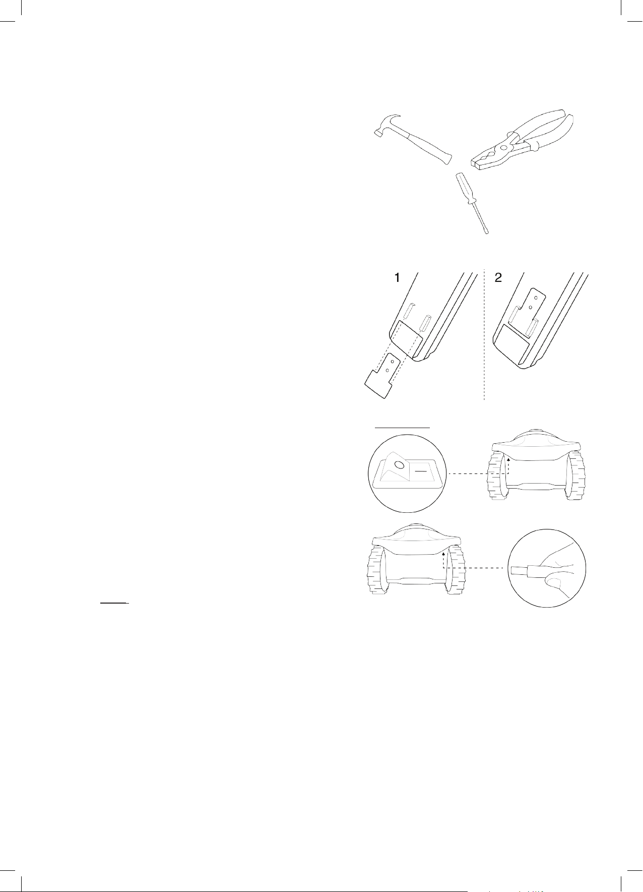
• Hold the Perimeter Switch and squeeze its side tabs (1) to
remove it from the back cover (2).
• Connect the Power Supply plug to the Perimeter Switch
board. Replace the cover.
• Connect the power supply to a regular power outlet (230V
/ 120V).
2
1
!
IMPORTANT
Choose a sheltered, dry, and well ventilated location that is NOT exposed to direct sunlight, water,
or rain.
• Press the ‘ON’ button on the Perimeter Switch.
A small ashing green light next to the ‘ON’ button indicates the system is on and functioning correctly.
The control panel has other indicators: a disconnected or broken Perimeter Wire and a poor splicing (connection)
in the Perimeter Wire.
!
The Power Supply is for indoor use ONLY.
ON button
ON button
Flashing light indicates
Flashing light
indicates the system
Indicates a disconnected /
disconnected/broken
Indicates poor splicing of
Indicates poor splicing of
perimeter wires or perimeter
perimiter wires or perimiter wire.
wire. which is too long
the system
Indicates a
broken wire
which is too long
The Perimeter Switch has an automatic shutoff feature. There is no need to turn it off after each use. The
Perimeter Switch will shut itself off after 12 hours of operation. You may manually turn it off by pressing the ON/
OFF button and holding it for 3 seconds. A beep will sound to indicate that the Perimeter Switch is off.
The Perimeter Switch can be operated by a rechargeable battery (available as an accessory – see Chapter
12).
28
Page 30

EN
Chapter 5 –
Before using Robomow for the rst time, you have to perform some simple preliminary settings.
Once the preparations are complete, your Robomow will be ready to mow your lawn.
Preparing Robomow
5.1 Adjust the Cung Height
Safety Switch
Blade Cutting Range: 15 – 60 mm (0.6 – 2.4 inches)
To adjust the cutting height of the blade, do the following:
CAUTION! ALWAYS TURN THE SAFETY SWITCH OFF
BEFORE ADJUSTING THE CUTTING HEIGHT!
• Lift the front side of the mower.
• Turn the knob while pushing it down.
• To raise the cutting height, turn clockwise.
• To lower the cutting height, turn anticlockwise
• The cutting height is displayed at the side of the mower.
Cutting height adjustment
5.2 One-Time Setup (Step by Step)
Make sure the Safety Switch is on and the Power Box is
plugged in before starting the One-Time Setup process.
The mower is now ready to perform the One-Time Setup
process.
!
IMPORTANT
arrow buttons together for more than 4 seconds. This will invoke Factory Defaults (“Out of the Box”
settings).
5.2.1 Using the Operating Panel
Use the buttons on the Operating Panel as follows:
• Press the ‘Right’ or ‘Left’ arrows until your desired option
is displayed.
• Press OK to select the value shown on the display.
• Press ‘Back’ (STOP) to go back or to cancel.
!
To restart the One-Time Setup process press and hold STOP + Settings + Left
Right/Left arrows
LOW
ok
STOP
HIGHLOW
HIGH
5.2.2 Choose Measurements Units and Formats
Area / Distance Temp. Clock
EU Meter Celsius 24 Hours
US Foot Fahrenheit
12 Hours
(AM / PM)
Settings button
29
Page 31

5.2.3 Set Day and Time
• Scroll to set the Day and press OK to conrm.
• Scroll to set the Time and press OK to conrm.
5.2.4 Main Zone Area
• Scroll to select an approximate area (EU- m² / US- ft²) for the Main Zone,
where the Base Station is installed.
If an additional zone (Sub-Zone or Separated Zone) exists, do not include it in
main zone’s area (it will be set separately).
Note – It is necessary to complete the above settings (5.2.2 – 5.2.3) in order to operate the mower. Every
press on the STOP button will change the screen one step back in the process.
5.2.5 Test Base Station
• After setting the area, U001 (Test Base Station Position) is
displayed.
• Place Robomow inside the lawn, approximately 3 m (10 ft.) in
front of the Base Station, facing the Perimeter Wire and press
OK to start the test.
• Robomow drives towards the Base Station:
If the mower does not start the test, then one of
the following messages will be displayed:
E3 (
No Wire Signal
Box is connected to the power outlet and that
the Extension Cable is connected at both ends,
from the Power Box to the Base Station.
U029 (
Perimeter Wire has been connected in the
opposite direction. Swap the wires at the plot
connector.
• Robomow will enter the Base Station, drive back, wait in front of
the Base Station, and display
Swap wires in plot connector
Position
)
– Conrm that the Power
U002
(
Peg Base).
)
– The
If
U051
(Reposion Base Staon)
displayed:
• Move the Base Station slightly to align it with
the Perimeter Wire.
• Check for any obstacles that may interfere
with the mower’s entrance to the Base
Station.
• While ‘U002’ (Peg Base) is displayed, insert the remaining Stakes
of the Base Station to secure it to the ground and press OK.
message is
30
Page 32

EN
5.2.6 Test Wire
• U003 is displayed (Test Wire Posion) – press OK.
• Robomow will follow the wire along the edge to test the
wire position.
Walk alongside Robomow while it is following the edge.
Having completed the process, Robomow will enter the
Base Station and the setup process will be completed.
• If, at any point, you wish the mower to drive closer to the
edge to enlarge the covered area, press Stop (‘U003’ is
displayed –
- Move the wire slightly outward.
- Place the mower in front of the changed section of
wire.
- Press OK to continue the ‘‘Test Wire Position’ process.
Position
If the mower collides with obstacles along the
edge, the mower will stop and drive backwards
‘
U052
’ (
with
• Move the wire slightly inward.
• Press OK to continue the Wire Test.
Adjust Wire
Test Wire Posion
)
displayed:
):
• If you want to quit the setup process, press and hold the
STOP button for 3 seconds. The screen will change to
the Main Display (current time).
• After completing the Test Wire Position, test the mower
in Near Wire Follow mode to conrm it completes the
drive near the wire smoothly, without acquiring any
adjacent wire or hitting any obstacle on its way to the
Base Station.
• If the mower fails to complete the Near Wire Follow
smoothly to the Base Station, then reduce the Near Wire
Follow Distance (Menu P004) and repeat the test until it
will complete the drive smoothly.
!
IMPORTANT
arrow buttons together for more than 4 seconds. This will invoke Factory Defaults (“Out of the
Box” settings).
!
To restart the One-Time Setup process press and hold STOP + Settings + Left
5.2.7 After Setup is Completed
Once the wire setup is complete, drive additional pegs at a
distance of approximately 0.75 m (2.5 ft.) apart.
• Use additional pegs in areas where there are bumps or
dips in the lawn.
If needed, purchase extra pegs.
• Inspect the wire installation for tripping hazards.
From this point on Robomow is ready to be charged.
Once fully charged it will automatically mow your lawn.
Note!
The rst charging may take longer then usual (up to 24 hours).
31
Page 33

Chapter 6 –
AM
Mo
Tu We Th Fr Sa Su
Robomow Operation
6.1 Automac Operaon
o Once the One-Time Setup is nished, Robomow will be set to perform automatically the following cycle of
mowing operations:
- When the battery is fully charged, Robomow will automatically depart from the Base Station.
- It will mow the lawn.
- It will start searching for the Base Station, when the battery level gets low (Robomow will not mow when
it is searching for the Base Station).
- It will recharge the battery and get ready for the next scheduled operation.
- It will continue mowing until it completes the required number of mowing hours (end of a Mowing Cycle).
Note: Robomow mows the Edge of the entire lawn only on the rst mowing operation of each Mowing Cycle.
In the rest of operations Robomow mows the lawn without the Edge. When Mowing Frequency (p001 in
Section 6.4.2) is set to HIGH, Robomow will mow the Edge twice a week.
o The required mowing time for a single mowing cycle is automatically derived from the Area setting for your
lawn.
o In case the required mowing time within a mowing cycle needs to be adjusted (increased/decreased) to
achieve better mowing results, it can be done using the Mowing Hours menu – see Section 6.4.2.
o Robomow usually performs several consecutive mowing operations until it completes a full mowing cycle
required for the lawn. After completing a mowing cycle Robomow will rest until the next cycle should begin.
The interval between mowing cycles is dened by the Mowing Frequency menu – see Section 6.4.2. The
default setting is to perform two complete mowing cycles per week (Medium Mowing Frequency)
o Robomow stays in the Base Station during the default Inactive Time (All day Sunday and nighttime daily
23:00 to 06:00). Inactive Time may be changed – see Section 6.4.1.3.
Note!
Robomow has the power to mow high grass. However when mowing high grass during the rst use or the rst
mowing of the season, initially you will see uneven patches of grass.
Please be patient as it may take a few days to one week to overcome and bring the lawn to an even height and
consistency.
6.2 Operang Panel
Operating Panel and buttons:
User / Error messages
Mower is in the
Base Staon
indicator
Days of the week
Baery and
Charging
indicator
Red lit constantly – Low Baery
Green blinking – Charging
Green lit constantly – Fully Charged
Day and Time
seng indicator
32
Mowing Hours (%)
seng indicator
Rain Sensor
Area seng indicator
Inacve Time
seng indicator
Page 34

EN
ok
STOP
OK to choose /
approve selecon
Mowing with Edge / Le
arrow
Sengs
6.3 Manual Operaon
Mowing without Edge /
Right arrow
GO to Base (Home)
Stop (during operaon) /
Back while in the menu
Manual Operation is used when you want to manually send the mower to mow your lawn, regardless the
Automatic Operation’s schedule.
To initiate Manual Operation, while Robomow is at the Base Station, press one of the buttons (except the STOP
button) to show the display.
If the battery is fully charged and the Automatic Operation is enabled (see Section 7.3), then the start time of the
next operation is displayed, otherwise the current day and time are displayed.
Once the display is shown, choose the operation mode you want as provided in the table below:
Operation Mode Child Lock is Off Child Lock is On
Mowing with Edge – Mowing
the edge of the entire lawn before
starting to mow the inner area of
a selected zone.
It is recommended to use this
mode once or twice a week,
depending on how fast the grass
is growing.
Mowing without Edge – Mowing
only the inner area of a selected
zone without the edge.
It is recommended to use this
mode only in the rst operation of
each Mowing Cycle.
Press the ‘Edge before mowing’
(left arrow) button once
Press the ‘Mowing’ (right arrow)
button once
Press the ‘Edge before mowing’
(left arrow) button then press OK
Press the ‘Mowing’ (right
arrow) button then press OK
Note – if a Sub-Zone is dened, L1 (Main Zone) will be displayed when you choose an operating mode. Use the
arrow buttons to scroll and choose the required zone to be mowed and press OK.
33
Page 35

6.4 Menu Opons
There are several levels of menu options that can be set in your Robomow:
A. Basic Settings
B. Advanced Settings
C. Robomow App Settings
6.4.1 Basic Settings
The Basic Settings are the most common menu options changed by the user. Each of the Basic Settings has an
icon on the mower (refer to 6.2 – Operating Panel) that is lit to indicate the selected menu option.
o To change Basic Settings, press the ‘Settings’ button.
o Every press on the Setting button will move between the following 4 menu options:
6.4.1.1 Day and Time – Set the current Day and Time.
Press the ‘Settings’ button so the ‘Day and Time’ (Clock) icon is constantly lit.
‘Day’ is blinking Scroll to the required day and press OK to conrm;
‘Hours’ is blinking Scroll to the required hour and press OK to conrm;
‘Minutes’ is blinking Scroll to the required min and press OK to conrm;
Note! If the mower is switched off and then back on, the ‘Day’ and ‘Time’ will start blinking to indicate
that the day and the time should be re-set.
6.4.1.2 Mowing Hours (%) – increase/decrease the number of mowing hours (in %) needed to cover the lawn
size.
Press the ‘Settings’ button twice until the ‘Mowing Hours (%)’ LED is constantly lit.
Use the scrolling arrows to adjust the number of mowing hours (in %) and press OK to conrm;
The default value of this setting is 100% and it can be changed from 50% to 150%.
Example: a value of 120%, means that Robomow will run 20% more hours on the lawn.
6.4.1.3 Inactive Time – Set times when the mower will be inactive. Inactive operating times can be set for
specic day(s) of the week, and for specic hours for all days in the week.
Inactive Day(s) denes the day(s) when the mower will be inactive (Default: Sunday).
Inactive Hours dene the hours when Robomow will not mow and stays in the Base Station (Default:
23:00-06:00)
IMPORTANT! It is required to go through the entire Inactive Days and Hours sequence in order to save
the settings. Pressing STOP before completing the whole sequence will not save the settings.
To change the Inactive Time, it is required to perform the following steps:
• Press the ‘Settings’ button 3 times until the ‘Inactive Time’ icon is constantly lit.
• The current Inactive Day(s) will constantly lit.
• Press the OK button; ‘Mon’ will start blinking.
- Press the RIGHT arrow to scroll to the day you want to set.
- Press ‘OK’ to toggle between ‘Active’ and ‘Inactive’ options for that day:
The LED is lit – ‘Inactive Day’ (mower will stay in the Base Station all day).
The LED is off – available day for mowing.
Press the RIGHT arrow to scroll to the next day you want to set
• Scroll through all the days to the right until the ‘Inactive Hours’ will start blinking.
• First set the time, at which the Inactive Hours start and press ‘OK’. Then set the time at which the
Inactive Hours will end.
• Robomow will not operate during the Inactive Hours throughout all days of the week.
• If too many days/hours have been deactivated relative to the zone area, then ‘E8’ (Decrease Inactive
Time) will be displayed – you need to decrease the number of inactive time so that the mower will
have enough time to mow your lawn.
• To set the ‘Inactive Hours’ to ‘Off’ set the same time for the start and the end (i.e.: 00:00 to 00:00).
• Only one window of Inactive Hours can be set in the Basic Settings. To open an additional window of
Inactive Hours use the Robomow App.
34
Page 36

EN
6.4.1.4 Area – Update the size of the lawn in case it has been changed.
• Press the ‘Setting’ button 4 times until the Area icon is blinking.
• Scroll to change the area and press ‘OK’ to conrm.
• If more than one zone is dened, then rst scroll to select the zone you want to edit and set the area
for that zone as described above.
Names of zones are as follows:
L1 – Main Zone
L2 – Separated Zone A
L3 – Separated Zone B
A1 – Sub-Zone 1
A2 – Sub-Zone 2
A3 – Sub-Zone 3
A4 – Sub-Zone 4
6.4.2 Advanced Settings
The Advanced Settings are additional menu options that are not changed very often and thus are not included
in the Basic Settings.
• To change any option/feature in the Advanced Settings, press the ‘Settings’ button continuously for 3 Sec.
• Menu ‘P001’ is displayed. Use the arrows to scroll to the setting you want to change, and then press OK.
• Use the arrow button to change the setting and press OK to conrm.
• Scroll to change additional menu options or press STOP to go back to the main display.
Below are the Advanced Settings options:
Screen Seng Descripon Opons
• Controls the frequency of mowing cycles in a particular
zone of your lawn.
• The default mowing frequency is Medium (equivalent to two
mowing cycles in a week). It means that Robomow will complete
the entire mowing of your lawn twice a week.
• The numbers in the menu represent the following values of
mowing frequency:
1 – LOW (one mowing cycle in a week)
2 – MEDIUM (two mowing cycles in a week)
3 – HIGH (equivalent to daily mowing)
• The ‘Mowing Frequency’ option is only available for zones where a
base station is installed. If you have dened at least one seprated
zone with a base station (see menus P013 and P014), then you
will be prompted to select the relevant zone before changing the
setting (L1 stands for the Main Zone, L2 stands for Separated
Zone A, etc.)
• During off-season when the growth rate of the grass is slower,
it is recommended to change the Mowing Frequency to ‘LOW’.
This resting period helps the grass and prolongs the lifetime of
the mower.
• Grass growth rate changes during the year (depending on
temperature, grass type, fertilizing etc.).
• High fertilization and favorable weather conditions may cause the
grass to grow faster. In such cases, set the ‘Mowing Frequency’
option to High.
• In case there is a large perimeter island (a swimming pool, a pond, a
large ower bed, etc.) in a particular zone, it is recommended to set
this setting to On. This will prevent the mower from following the wire
around such island, while returning to the Base Station.
• When the Islands feature is set to On, the mower will execute a
special method of searching for the Base Station. As a result it may
take the mower more time to arrive to the Base Station.
• See also menu P006 below.
1/2/3
On/OFF
P001
P002
Mowing
Frequency
(Default =
Islands (Default =
2)
OFF)
35
Page 37

Screen Seng Descripon Opons
• When Robomow completes its operation, or when the ‘Home’ button
instructs it to Go To Base, it drives itself to the Base Station.
• Robomow drives along the Perimeter Wire with a dynamic offset (not
P003
P004
P005
P006
P007
P008
P009
Near Wire Follow
(Default = ON)
Max Near Wire
Follow Distance
(Default =
changed based on
the lawn area)
Min Near Wire
Follow Distance
(Default = 1)
Near Wire Follow
Test
Rain Sensor
(Default = On)
Rain Sensor
Sensitivity
(Default = 25)
Edging On/Off
(Default = ON)
centered) to prevent wheel tracks along the same path. This return
behavior can be turned off.
• This menu is not available for RC304 and MC400 models.
• For all other models, the Near Wire Follow feature can be enabled
and congured for a Sub-Zone as well.
• The maximum distance Robomow will drive from the wire when
returning to the Base Station.
• The distance does not represent actual units of measurement.
• The offset Distance values range from 1 to 12. They represent
different distances from the wire.
• The higher the Distance setting, the smaller the probability of tracks
along the perimeter.
• Perimeter Islands that are relatively close to the Perimeter Wire or
narrow passages may prevent the mower to complete its drive to the
Base Station with ‘Near Wire Follow’ mode. In such cases decrease
the distance to allow the mower to complete the drive to the Base
Station.
• This menu is not available for RC304 and MC400 models.
• For all other models, the Near Wire Follow feature can be enabled
and congured for a Sub-Zone as well.
• The minimum distance Robomow will drive from the wire when
returning to the Base Station.
• The larger the number, the bigger the distance the mower will drive
from the wire while returns to the Base Station.
• This menu is not available for RC304 and MC400 models.
• For all other models, the Near Wire Follow feature can be enabled
and congured for a Sub-Zone as well.
• Enables to test the mower in the max ‘Near wire Follow Distance’
that is dened in menu P004.
• If the mower is not able to complete the drive in ‘Near Wire’ mode
smoothly, then it is recommended to reduce the max distance set in
menu P004.
• This menu is not available for RC304 and MC400 models.
• The Rain Sensor feature halts operation on rainy or highly humid
weather.
• This is recommended for the health of the lawn. However, mowing
wet grass does not present any technical problem.
Note! It may take a few minutes before Robomow detects rainy or
humid conditions. This is done in order to avoid false-detections. As
soon as the mower detects rain, it halts current mowing operation
and starts searching for the Base Station. When the ‘Islands’ feature
is set to On (see menu P002 above), the mower will execute a special
method of searching for the Base Station. As a result it may take the
mower more time (up to 20-30 minutes) to arrive to the Base Station.
• Robomow detects rain when the current reading value is below the
set Sensitivity value and postpones operation.
• The higher the Sensitivity setting, the more sensitive Robomow is to
rain detection.
• Edging is a special mode, in which Robomow follows the perimeter
wire for complete and accurate mowing of the lawn edges.
• In lawns where the edge is not maintained well and the mower fails
to complete the drive along the edge of the lawn, it is recommended
to set Edging to ‘Off’.
• Setting Edging to ‘Off’ disables Edging mode in automatic departures
from the station, but still allows edge-mowing when pressing the
‘Edge’ mode button on the operating panel.
On/OFF
1-12
1-5
On/OFF
0-30
On/OFF
36
Page 38

EN
Screen Seng Descripon Opons
• The Child Lock feature locks the buttons to prevent unintended
operation, especially by children and pets.
• If the Child Lock is set to ‘On’, to operate the mower it is required to
rst press one of the operating mode buttons and then to press the
OK button to conrm.
• The Anti-Theft / Disabling Device feature alarms the surroundings
in the event of an unintended use or removal of the mower from its
designated area.
• To turn the Anti-Theft / Disabling Device On for the rst time, set it to
‘On’ and choose a PIN code of 4 digits.
Tip: Select a number you can remember. Write it down (bottom of
Chapter 10), and keep it in a safe place.
• When the Anti-Theft / Disabling Device system is activated, 0000 will
be displayed. Enter your 4-digit code to deactivate the Anti-Theft /
Disabling Device.
• If the code is not entered, then the message is changed to U062
(Alarm will soon be activated). Enter the code, otherwise the alarm
will start.
• Allows changing of the Anti-Theft / Disabling Device PIN code.
• Enter a new code and then re-enter the new code for conrmation.
• This option should be used in a Separated Zone which has a
Base Station
• If you have dened more than one zone, then select the relevant
zone before changing the setting.
• Enables the addition of a Separated Zone.
• L2 is displayed for Separated Zone A – press OK.
• Scroll to set the area of the Separated Zone and press OK.
On/OFF
ON/OFF
1234
0000
On/OFF
L2
100
P010
P011
P012
P013
P014
Child Lock
(Default =
Anti-Theft /
Disabling Device
(Default = OFF)
Anti-Theft /
Disabling Device
Change PIN code
Base Station
(Default = ON)
Add Separated
OFF)
Zone
P015
P016
P017
P018
P019
P020
P021
Remove Zone
Sound
(Default = ON)
Mobile
Communication
System
(Default = OFF)
Statistics (Default
OFF)
=
Bluetooth Remote
Control Pairing
Last Termination
Event
Program On/Off
(Default = ON)
• Enables the removal of a Separated Zone or a Sub-Zone.
• Choose the Zone you want to remove and press OK.
• Use the Sound option to turn all non-safety sounds off.
• Enables remote communication with the mower using a GSM
Module Accessory, which can be purchased separately.
• For more information, refer to Section 12 – Accessories.
• This menu is displayed only if P018 is set to ‘On’.
• Enables to send the operation statistics from the mower to the
manufacturer for diagnostics in case of problems.
• Enables the pairing process between your Robomow and
an outdoor Bluetooth Remote Control that is available as an
accessory (Refer to Paragraph 12 Accessories).
• Enables the Behavior View of the special display (may be required
by a Service Station)
• This menu enables or disables (pauses) Automatic Operation
either in the main zone (‘L1’), one of the Sub-Zones (‘A1/ A2/ A3/
A4’) or in the entire lawn (‘All’).
• This menu is only relevant when the Automatic operation is
enabled on the Power Box (see chapter 7.3)
• When Program is set to Off in a particular zone, the mower will
skip the operation in that zone, but will continue to mow all the
other zones.
• Note! If Program is set to ON at least in one zone, the mower will
continue to mow the edge of the entire lawn at the beginning of
each mowing cycle, as described in Section 6.1.
L2/L3
/A2/A3/
A1
A4
On/OFF
On/OFF
On/OFF
All
L1
/A2/A3/
A1
A4
/OFF
On
37
Page 39

Screen Seng Descripon Opons
• Enables the addition of a Sub-Zone. Maximal number of SubZones may be different for each Robomow model.
• A1/A2/A3/A4 (name of the rst available sub-zone) is displayed
- press OK.
• If the mower is not at the Base Station, then ‘U044’ (“Place the
mower in the Base Station”) is displayed. Place the mower in the
P022
P023
P024
P025
P026
Add Sub-Zone
Update Distance
To Sub-Zone
SmartMow
(Default = OFF)
SmartMow
Edge Overlap
(Default = 10)
TurboMow
(Default = OFF)
Base Station and press OK.
• The mower will start moving towards the Sub-Zone.
• Scroll to set the area of the Sub-Zone and press OK.
• Note! This process is not a part of the One-Time Setup (see
Section 5.2)
• The area setting of a Sub-Zone can be later updated through the
‘Area’ menu of the Basic Settings (see Section 6.4.1)
• The distance to Sub-Zone’s entry point can be update later
through menu P023
• This menu is shown only if a Sub-Zone has been dened.
• It allows to update the distance to Sub-Zone’s entry point.
• Scroll to choose the required Sub-Zone (A1/A2/A3/A4) and press
OK to update the distance to the entry point.
• SmartMow feature allows more efcient mowing operation
through the smooth and continuous turns when reaching lawn’s
edge.
• When this feature is enabled for the rst time in a particular
zone, it may require the mower to cross the lawn and “touch”
the perimeter wire several times (to perform an initial calibration
of the algorithm), before it will start performing smooth turns at
lawn’s edge.
• If there is more than one zone dened, then there is an option
to enable this feature for a particular zone or for the entire lawn
(‘All’).
• Please note! This feature may not be equally efcient on all lawns
or on different sections of a particular lawn, especially if a lawn
area is small or has narrow areas, big islands or slopes.
• Allows adjusting the degree of overlapping with lawn’s edge,
when performing the smooth and continuous turns in SmartMow
mode.
• Increasing this value will cause a higher overlapping with lawn’s
edge (for better mowing results), but at some point may prevent
the mower from performing a smooth turn.
• If there is more than one zone dened, this setting may be set per
zone or for the entire lawn (‘All’).
• TurboMow feature allows faster and stronger mowing of a high
grass during the rst cut of the season.
• When a mower is operated for the rst time, or if the Factory
Defaults (“Out of the Box” settings - see Section 5.2) are invoked,
this feature is automatically set to ON to provide better mowing
results already after the initial mowing cycle. At the end of the
initial mowing cycle, the feature will be automatically disabled (set
to OFF).
• This menu allows to activate TurboMow feature manually. ‘U094’
(“Raise mowing height when activating the TurboMow mode.”)
will be displayed. At the end of the cycle the feature will be
automatically deactivated (set to OFF).
• When the TurboMow feature is activated, the initial mowing cycle
will be longer and noisier than the next mowing cycles.
A1/A2/A3/
A4
100
All
/L2/L3
L1
/A2/A3/
A1
A4
/OFF
On
5-30
On/OFF
38
Page 40

EN
6.4.3 Robomow App Settings
Using the Robomow App you will have access to additional menu options that are not available on the mower,
such as an option to dene an external setup of a Base Station or an option to set an additional window of
Inactive Hours.
6.5 Operaon in a Non-Base Zone (using a Perimeter Switch)
In order for Robomow to operate in a Non-Base Zone, the Perimeter Switch has to be turned on and the mower
should be inside the active perimeter area.
• Verify that the Perimeter Switch is connected to the zone to be mowed.
• Press the ‘ON’ button to turn on the Perimeter Switch.
• Drive/carry Robomow to the lawn area. Refer to “Transportation” part of Section 1.3 for carrying instructions.
• To initiate the operation, choose the operation mode you want, press the arrow buttons to choose the Zone
you want to mow and press OK to start operation (refer to Section 6.3).
• When Robomow completes the mowing, it will stay on the lawn. You will have to drive/carry it back to its place
for charging.
39
Page 41

Chapter 7 –
Using The Power Box
7.1 Power Box Alerts
Event Description
Docking Indicator is lit. The mower is in its Base Station.
Operating Indicator is lit The mower is not in its Base Station.
Automatic Operation On/
OffIndicator is lit.
‘PAUS’ will be displayed on
the mower.
Wire Indicator – Flashes and
Beeps
All Indicators ash
All Indicators ash and Buzzer
sounds for 10
Note – To stop an alert when sounding, press the On/Off Button.
seconds.
Automatic Operation is paused.
The Perimeter Wire is cut,
disconnected, or too long.
The mower did not return to the Base
Station after 4 hours of departure.
When the mower is detected at the
Base Station, alerts will turn Off.
The Anti-Theft option is set to On,
and the mower was removed from
its Base Station when it was not
scheduled to operate.
Docking Indicator
Operating
Indicator
Automatic
Operation
Wire Indicator
7.2 Turn the Buzzer On/O
• Press and hold the On/Off button for 10 seconds.
- A short beep indicates On.
- A ash indicates Off.
7.3 Enable/Disable the Automac Operaon
• This option is used to disable (pause) a predened Automatic Operation (Program) of Robomow. This
option does not prevent Manual Operation (Section 6.3).
• Press and hold the Automatic Operation On/Off button for 2 seconds.
A red LED will be lit on the Power Box. ‘PAUS’ indication will be displayed on the mower:
o If Robomow is currently in the process of mowing:
- Robomow will complete the current mowing cycle.
- After completing the current mowing cycle, Robomow will stay in the Base Station and will not start
another mowing cycle.
• To Enable the Automatic Operation
o Press and hold the Program On/Off button for 2 seconds.
40
Page 42

EN
Chapter 8 –
Charging
8.1 Charging During the Season
The Base Station is the primary charging source when Robomow is docked and will maintain the optimal battery
charge while awaiting departure.
8.2 Charging Out of Season
During out of season months, such as winter, it is required to:
• Fully charge the battery in the Base Station till the Battery indicator is green and lit constantly.
LED indicators for charging:
- Red is lit constantly – Charge the battery.
- Green is blinking – During battery charging.
- Green is lit constantly – Battery is fully charged.
• Remove Robomow from its Base Station. Turn the Safety Switch off and store the mower in room temperature.
• If the mower is stored for more than 3 months, it is required to recharge the battery every 3 months till the Battery
indicator shows it is fully charged.
!
IMPORTANT
• The Safety Switch should be in ‘On’ position during
charging or recharging.
• Always charge your mower in a horizontal position
(at on the ground).
!
• The charging can be done in one of the following options:
Place the mower in the Base Station for charging.
1.
2.
Connect Robomow directly to the Power Box as follows:
- Disconnect the DC Cable coming from the Power Box to
the 15m Extension Cable and connect it to the rear side
of the mower as shown in the gure to the right.
• Once the season starts, just place Robomow in its Base
Station to begin automatic operation.
41
Page 43

Chapter 9 –
Troubleshooting and User Messages
9.1 General Error Codes
• Robomow continuously monitors its operation.
It produces error codes to assist you in running it
smoothly.
• A sticker containing the most common error codes
is provided in the box. You can place it on the mower
for your convenience.
• (*) E9 (See Troubleshooting in Manual) represents
errors that are not very common, and thus they
are not shown in the above Error Code Table. If
E9 is displayed, press the LEFT arrow to receive
a detailed Error Code. Then refer to section 9.2 for
more details.
• Usually, if the mower stops, an error code is
displayed. This display stays on for 5 minutes. If
you arrive later, the display will be blank.
• To wake Robomow up and see the last error code displayed prior to stopping, press the OK button on the
mower.
Robomow Error Codes Table
E1
E2
E3
E4
E5
E6
E7
E8
E9*
E5XX
Check Blade / Cutting Height
See Troubleshooting in Manual
Stuck in Place
Mower is Outside
No Wire Signal
Check Power
Check Drive
Front Wheel Problem
Decrease Inactive Time
Call Support
The following table displays all Error Codes and gives possible causes and corrective actions:
Display Message Probable Cause/Event Correcve Acons
- Move the mower away from this particular
location and restart operation.
- Rectify the reason for it getting stuck.
- Check the ground around the mower for
ditches or non-level ground. Fill with dirt
and level off.
- Check if the drive wheels are free to rotate
and nothing is blocking them.
- Verify that the cutting height is not set too
low for the grass condition - increase the
cutting height if needed.
- Check that the Perimeter Wire is not
too close to the edge – remove the wire
towards the inner side of the lawn.
- Conrm that the Perimeter Wire has been
laid according to the instructions in the
Manual.
- Do not include areas with very steep
slopes.
- Verify that the cutting height is not set too
low – Increase the cutting height.
- Place the mower inside the lawn and
renew the operation.
E1
E2
Stuck in Place
The mower is
Outside
- Robomow got stuck in place. It
cannot continue driving.
- Drive wheel motors have been
working under a severe load.
- Robomow has difculty turning
in place because the front wheel
is blocked by a ditch or non-level
ground.
- The Perimeter Wire is too close
to the edge of the lawn.
- The Perimeter Wire has been
laid the wrong way around a
perimeter island.
- The lawn slope is too steep
along the edge.
- Robomow does not succeed to
turn in place at the edge, and it is
causing the mower to slip out of
the designated area.
- Automatic operation is initiated
while the robot is placed out of
the Perimeter Wire loop.
42
Page 44

EN
Display Message Probable Cause/Event Correcve Acons
- Make sure the Base Station is connected to
the mains supply.
- Disconnect the Power Box from the mains
power and reconnect after 10 seconds.
- Check that the low voltage cable between
the Power Box and the Base Station is
connected.
- Check the LED indications on the Power
Box.
- Check the connection of the Perimeter Wire
to the Base Station / Perimeter Switch.
- Check the installation for cut wire. Repair
broken cable with the waterproofed
connector supplied in the box.
- Conrm Power Box is plugged into the
power outlet.
- Turn power on to the power outlet.
- Check the power outlet using another
appliance.
- Clean the contacts with a brush or piece of
cloth.
- Conrm a good connection of the Power
Box to the Base Station.
- CAUTION – Switch off the Safety Switch
before checking the blade.
- Inspect blade for foreign material or debris
preventing rotation.
- Clean out accumulated grass clippings using
a wooden stick.
- Check the drive wheels and remove the
grass or other objects.
- If Robomow has driven onto an obstacle,
Switch off the Safety Switch, raising the front
end: Remove or exclude the object from the
mowing area.
- If Robomow is being used on a slope too
steep for safe mowing, exclude this from the
mowing area.
- If high grass is preventing the front wheel
from fully turning on the ground, raise the
cutting height.
- If the ground contains large holes or
indentations where the front wheel can drop
into when passing across, ll these areas
with soil and level off.
E3
E4
E5
E6
E7
No Wire Signal
Check Power
Check Blade /
Cutting Height
Check Drive
Front Wheel
Problem
- Power Box/Perimeter Switch is not
turned on or not connected
- Power Box may need to be
restarted
- The Perimeter Wire is not
connected to the Base Station/
Perimeter Switch.
- The Perimeter Wire is cut.
- Power Box is not plugged in
properly into the power outlet.
- No power at the power outlet or
the main power is shut off.
- The mower or Base Station
contacts are dirty.
- Charging is not detected, although
there is a physical contact between
the mower and the Base Station
contacts.
- Mowing motor has faced overcurrent conditions for too long as a
result of high grass or an obstacle
that is stuck or wrapped around
the blade.
- Something is preventing a blade
from rotating freely (Accumulated
grass clippings under the mowing
deck; rope or similar object
wrapped around mowing blade).
- Grass or other object has wrapped
around the drive wheel.
- The drive motors have been
working under severe load for too
long.
- The Front Wheel has left the
ground for too long during
operation.
43
Page 45

Display Message Probable Cause/Event Correcve Acons
- Too many Inactive Days and/or
Hours have been set for your lawn
area. Current settings will not be
E8
E9
Decrease
Inactive Time
See
Troubleshooting
in Manual
changed.
- Mowing Frequency is too high for
current settings of Inactive Time.
The Inactive Time settings will be
set to defaults.
- Area setting is too high for current
settings of Inactive Time. The
Inactive Time settings will be set to
defaults.
- E 9 is displayed for all other
messages that are not listed in the
above table.
- Decrease the number of Inactive Days and/
or the number of Inactive Hours to allow
Robomow to complete mowing your lawn.
- Decrease Mowing Frequency (see p001 in
the table in Section 6.4.2)
- Decrease Area setting
- Press the ‘Right arrow’ button to receive the
stop reason number and refer to the next
table for more details about the stop reason,
causes, and actions.
9.2 Detailed Error Codes
If the above table (Section 9.1) does not give enough information to help solve the problem, then press the LEFT
arrow while the Error Code is displayed in order to receive a detailed error code for the problem and refer to the
table below:
Display Message Probable Cause/Event Correcve Acons
0010
0011
0012
0014
0015
0016
0020
0021
- The mowing motor has been
Mow Overheat
Drive Overheat
No wire signal - See E3 in the above table
Front wheel
problem
Button pressed
Low
temperature
Rain detected
Check mowing
height
working under a severe load for too
long.
- The drive motors have been working
under a severe load for too long.
- See E7 in the above table
- One of the operating panel buttons
is constantly pressed.
- Mower does not depart
automatically from the Base Station
when the ambient temperature is
lower than 5ºC (41ºF).
- Information - When the temperature
is below 5ºC (41ºF) the grass does
not grow or grows very slowly.
However Manual Depart is enabled.
- The operation is delayed as
Robomow detects rain.
- Robomow should resume operation
30 minutes after it stops to detect
the rain.
- Mowing motor has faced over-
current conditionsfor too long as a
result of high grass or an obstacle
that is stuck or wrapped around the
blade.
- Something is preventing the blade
from rotating freely.
- Severe grass accumulation under
the mowing deck, rope, or similar
object is wrapped around mowing
blade.
- No need for action – Robomow will renew
automatically the operation after the mowing
motor will cool down.
- No need to do anything.
- Robomow will renew the operation
automatically as soon as the drive motor will
cool down.
- Press ‘OK’ to conrm the message and
continue operation. This message is displayed
to inform only.
- No need to do anything.
- Robomow will renew the operation
automatically as soon as the ambiance
temperature will rise above 5ºC (41ºF).
- No need for action.
- The message is displayed until Robomow will
not detect rain and then will start mowing.
- CAUTION – Switch Off the Safety Switch
before checking the blade.
- Inspect the blade for foreign material or debris
preventing rotation.
- Clean out accumulated grass clippings using
a wooden stick.
44
Page 46

EN
Display Message Probable Cause/Event Correcve Acons
- CAUTION – Switch Off the Safety Switch
before checking the blade.
- Remove the mower from the Base Station.
Inspect the blade for foreign material or debris
preventing rotation.
- Adjust the Base Station position.
- Clean the contacts with a brush or piece of
cloth.
- Check to insure the mower is not stuck,
causing the drive wheels to slip.
- Check the ground around the mower for holes
or indentations. Fill with ground and level off.
- Check if the drive wheels are free to rotate
and nothing is blocking them.
- Move the mower away from this particular
location and restart operation.
- Remove the wire towards the inner part of the
lawn.
- Do not include this area because of its steep
slopes.
- Fill holes and pits in the ground.
- Increase the cutting height.
- Place the mower inside the lawn and renew
the operation.
- Decrease the mowing hours % you have set
for the zone(s) in your lawn.
0022
0023
0026
0027
0028
0030
0031
0060
0061
Check mowing
motor
Check power - See E4 in the above table
Base problem
Start Elsewhere
Cross Outside
Start Inside
Stuck in place - See E1 in the above table
Check mowing
hours (%)
Decrease
Inactive Time
- Mowing motor has faced over-
current for too long in the Base
Station before starting the operation.
- Robomow fails to enter the Base
Station several consecutive times.
- Drive wheel motors have been
working under severe load during
automatic or manual operation.
- The Perimeter Wire is too close to
the edge.
- The lawn slope is too steep.
- Robomow does not succeed to
turn in place at the edge and it
causes the mower to slip out of the
designated area.
- Robomow has slipped out of the
Perimeter Wire lope because of
sloping area or wet grass.
- Automatic operation is initiated
while the robot is placed out of the
Perimeter Wire loop.
- The mowing hours % value you
have set is too high for your lawn
area.
- See E8 in the above table
45
Page 47

9.3 User Messages
The next table gives information about User Messages that can be displayed on the mower:
Display Message / Descripon Required Acon
BATT
PAUS
U001
U002
U003
U004
U017
U018
U024
U025
U029
U032
U041
U042
U043
U044
U051
Recharge Battery. Low battery voltage. Recharge the Battery.
Automatic operation is paused via the Power Box
or the Program On/Off menu.
Test Base Station position.
Displayed during the One-Time Setup.
Peg Base Station.
Displayed during the One-Time Setup.
Test wire position.
Displayed during the One-Time Setup.
Wire Test ended (during the One-Time Setup)
Displayed only when using the Robomow App.
Operation time is completed as expected. No action is required.
Operation time is shorter than expected Battery run time is too short. Replace Battery.
Keep charging if not used.
Displayed only if the mower is disconnected from
a Charging Adaptor.
Switch Off before lifting
Change the wires in plot connector
Displayed during the One-Time Setup.
Switch on the System Switch.
Displayed if the mower is connected to charging,
but the System Switch is ‘Off’.
Press the STOP button at Sub-Zone entry.
Learning edge distance.
Going to Sub-Zone entry point. Displayed when
the mower drives towards the Sub-Zone.
Place the mower in the Base Station.
Reposition the Base Station position.
Displayed during the One-Time Setup.
Enable automatic operation on the Power Box
or via the Program On/Off menu (refer to section
7.3 or section 6.4.2, menu P021).
Refer to section 5.2.5 in the User Manual.
Refer to section 5.2.5 in the User Manual.
Refer to section 5.2.6 in the User Manual
No action is required.
It is recommended to keep the mower
connected to the Power Supply when not in use.
It is required to switch Off the System Switch
before lifting and carrying the mower.
Swap the wires at the plot connector.
Refer to section 5.2.5 in the User Manual.
Switch the System Switch to ‘On’.
Press STOP at the point you want the mower to
start mowing the Sub-Zone.
The mower learns the distance of the Perimeter
Wire in a Separated Zone. Press STOP to learn
the distance.
No action is required.
Place the mower in the Base Station before
starting the process of adding a Sub-Zone.
Refer to section 5.2.5 in the User Manual.
46
U052
U062
U064
U086
U087
U088
Adjust Wire Refer to section 5.2.6 in the User Manual.
An alarm will soon be activated.
The Searching Base Station operation cannot be
performed
Waiting for the signal…
Robomow has stopped the operation. It does not
detect a signal.
Mow motor overheat, Cooling…
The mowing motor has been working under a
severe load for too long.
Drive motor overheat, Cooling…
The drive motors have been working under a
severe load for too long.
This message warns you to enter the PIN code
before the Anti-Theft alarm will sound.
When choosing the ‘Home’ button in a zone
without a Base Station.
Check the power to the Power Box.
There may be an electrical power interruption.
There is no need to do anything. Robomow will
renew operation as soon as the power is back
on.
No need for action – Robomow will renew
automatically the operation, as the mowing
motor will cool down.
No need to do anything.
Robomow will renew the operation automatically
as soon as the drive motor will cool down.
Page 48

EN
Display Message / Descripon Required Acon
U089
U090-
U093
U094
Child Lock feature is activated.
The operational buttons are locked to prevent
unintended operation, especially by children.
Sub-Zone 1/2/3/4 entry problem.
The mower eitherfails to leave/bypassthe Base
Station on its way to the Sub-Zone,orfails to enter
the Sub-Zone.
The mower will try to reach the Sub-Zone every
two hours. If the mower fails to reach the SubZone within threeattempts, it will stay in the Base
Station until the end of current mowing cycle.
The mower will not skip to the next Sub-Zone (if
there are any), if it fails to reach the current one.
Raise mowing height when activating the
TurboMow mode.
To operate the mower, rst press one of the
operating mode buttons and then to press the
OK button to conrm.
Try to startmanual mowing (refer to section
6.3 – Manual Operation). Check if something
disturbs mower’s driving backwards and/or
bypassing the Base Station. Conrm the mower
drives along the perimeter wire and doesn’t fall
off the lawn’s edge, when it departs from the
Base Station.
Conrm that the mower is able to follow the
perimeter wire along the narrow pass untilit
reaches the Sub-Zone. Refer to section 4.3.3
for instructions on how to set a narrow pass
properly.
Refer to sections 5.1 and P026 in Section 6.4.2
in the User Manual.
9.4 Basic Troubleshoong
The next table will give details and possible causes of other faults, which do not provide error codes. If a fault
cannot be dealt with using these tables, please call your service provider.
Problem
Encountered
Poor quality of
mowing
Mower doesn’t
nd the Base
Station
Mower doesn’t
depart from the
Base Station for
a long time
Robomow
is noisy and
vibrates
Mower does not
dock properly
and sometimes
misses the Base
Station contacts
Probable Cause/Event Correcve Acons
- Dull blade - Replace blade.
- It is recommended to cut less than a 1/3 of the
green part of the grass.
- The grass is too high in relation to the set
cutting height.
- The grass is wet and causes
accumulation of grass clippings around
the blade.
- There is a Perimeter Island or a Narrow
Passage that prevents the mower to
complete its drive towards the Base
Station in Near Wire Follow mode.
- There are several possible reasons for a
non-departure, including inactive times,
rain detection, etc.
- Damaged or unbalanced blade
- Height differences between the lawn and
the Base Station surface.
- The wire underneath the Base Station is
not tight and placed in the middle of the
Station.
- The Base Station is set up on a side
slope.
- The Base Station is placed too close to
the corner of the lawn
- Set the cutting height to a higher position and
then successively lower.
- If it is during a fast growing season – change
the Mowing Frequency (refer to Section 6.4.2 –
P001).
- For best cut, operate Robomow when the grass
is dry. Do no to mow in the early morning hours.
- Switch Off the Safety Switch and use heavy
gloves to clean and remove the grass clippings.
- Reduce the Near Wire Follow Distance in the
Settings menu from the default 7.
- Press and hold ‘Home’ button for 1 second
while the mower is in the Base Station. The
non-depart reason code will be displayed for
3 seconds. Refer to Section 9.4.1 for detailed
description of no-depart codes.
- Check if the lawn is free from branches, stones
or other objects that can damage the blade.
- Replace the blade
- Fill some ground to atten the lawn to the Base
Station to allow smooth entrance.
- Conrm the wire underneath the Base Station
is straight, tight, and centered below the Base
Station.
- Move the Base Station to a relatively level
ground.
- Move the Base Station so it is not within 3
meters after a corner.
47
Page 49

Problem
Encountered
Probable Cause/Event Correcve Acons
Uneven mowing
results
Robomow
operates during
Inactive Time.
Robomow
operates during
rain
Cut wire indicator
is ashing on
Power Box
- The time between operations is too long
because of long inactive time windows.
- Grass is growing very fast.
- The shape of the lawn is complicated
(Narrow Passages, obstacle and islands).
- The set area is smaller than the actual
lawn size.
- Wrong clock time is set in the mower.
- Rain Sensor is disabled or its sensitivity
is set too low
- The Islands feature is set to On. In this
case the mower is searching for the base
by moving around the lawn. This special
search method takes more time, and
may create an impression that the mower
is still mowing, while in fact it is already
searching for the Base Station.
- The Extension Cable is disconnected or
damaged between Power Box and the
Base Station.
- Perimeter Wire is cut.
- Minimize the Inactive Time windows to allow
Robomow to complete the Mowing Cycle faster
and to achieve even mowing results.
- - If it is during a fast growing season – change
the Mowing Frequency (refer to Section 6.4.2 –
P001).
- In a complicated lawn more time is required for
the mower to achieve better mowing results.
- Increase the mowing hours percentage (refer to
Section 6.4.1.2).
- Increase the zone area (refer to Section 6.4.1.4)
- Verify that the time on the mower is set correctly.
- Set the time (refer to Section 6.4.1.1).
- Reset the Inactive Time (refer to Section
6.4.1.3).
- Enable the Rain Sensor and adjust its sensitivity
if required (refer to Section 6.4.2 – P007/p008)
- No special action is required. For more
information about the Islands On/Off feature
refer to Section 6.4.2 – P002)
- Conrm the Extension Cable is plugged in and
wire leads are rmly attached.
- Walk along Perimeter Wire.
- Look for cuts or breaks in the wire.
- Repair with Robomow wire splice connectors.
- Scan the code and
watch the video
demonstrating the
Corrective Actions of
the “Perimeter Wire
is cut”.
The poor
connection
indicator is
ashing on
Power Box
48
- Poor connections
- Twisted cables or a screw terminal which
is insulated with insulation tape is not a
satisfactory splice.
- Soil moisture causes the conductors to
oxidize.
- Check and repair all loose, poor, or corroded
connections.
- Use the connectors supplied in the box. They
are waterproof and give a reliable electrical
connection.
Page 50

EN
9.4.1 Description of No-Depart Codes
Code Descripon Correcve Acon
00
01
02
03
04
05
07
08
09
11
12
13
14
15
16
17
18
None. Automatic departure is working properly None. Wait for the end of current charging cycle
Mower’s battery is not yet in the required state
forautomatic departure
Inactive Time is activated. No automatic
departure during Inactive Time
Mowing cycle is completed. Waiting for the next
scheduled operation
Humid conditions or rain were detected during
last 30 minutes.
The mower is switched off Switch on the Safety Switch
User response (interaction) is required in order to
continue current operation
Multiple consecutive mowing operations were
shorter than expected. Usually accompanied by
U018 (“Operation time is shorter than expected”)
One-Time setup is running
Automatic operation is disabled by menu P021
(see Section 6.4.2)
Automatic operation is put on pause bythe Power
Box
All week days are set as inactive days
The mower is being charged directly by the
Power Box (via the DC connector)
Battery cells are being balanced in special
charging mode
The mower is in the Base Station, but there is no
charging voltage supply
Low ambient temperature
Sub-Zone entry problem. The mower was unable
to enter one of the Sub-Zones
None. Wait for the end of current charging cycle.
May take longer than usual
None. Validate Inactive Time settings (see
Section 6.4.1.3)
None
- None. If the rain has stopped, wait for another
30 minutes at least
- If there was no any raining at all, consider
adjusting rain sensor’s sensitivity (see P008 in
Section 6.4.2) or call Robomow Hotline
Acknowledge the error message
- Inspect mower’s blade and drive wheels.
- Battery run-time may be too short.
One-Time setup should be completed before the
automatic operation can start
Enable automatic operation through menu p021
Enable automatic operation via the Power Box.
Validate Inactive Time settings (see Section
6.4.1.3)
Disconnect the DC cable from the mower. Put
the mower in the Base Station.
None. Wait for the end of current charging cycle.
May take longer than usual.
- Inspect Power Box’s connection to the Base
Station
- Conrm that nothing is blocking the charging
pins
None. The mower will automatically depart
when it gets warmer.
Refer to U090-U093 in Section 9.3
49
Page 51

Chapter 10 –
Designation Robotic Mower Robotic Mower Robotic Mower
Max Lawn Size 400 m
Base Station Included Included Included
Robot Dimensions 63x46x21cm/25x18x8” 63x46x21cm/25x18x8” 63x46x21cm/25x18x8”
Package Dimensions 80x54x33cm/32x21x13” 80x54x33cm/32x21x13” 80x54x33cm/32x21x13”
Robot Weight 11.1 kg / 24.5 lb. 11.4 kg / 25 lb. 11.1 kg / 25 lb.
Package Weight 21.3 kg / 46.9 lb. 22.4 kg / 49.4 lb. 23.1 kg / 50.9 lb.
Cutting Width 28 cm / 11” 28 cm / 11” 28 cm / 11”
Cutting Height 15-60 mm / 0.6”-2.4” 15-60 mm / 0.6”-2.4” 15-60 mm / 0.6”-2.4”
Mowing Power 200 Watts 200 Watts 200 Watts
Mowing Motors DC Brush DC Brush DC Brushless
Power Wheels Available Included Included
GSM Module Available Available Included
Noise Level
Battery Type 26V Lithium (LiFePO4) 26V Lithium (LiFePO4) 26V Lithium (LiFePO4)
Product Specication
RC304 RC308 RC312
2
/ 4400 ft
High Power: 67.6 dB measured (Guaranteed 69 dB)
2
The noise at the operator’s ears less than 70 dB
800 m2 / 8600 ft
2
1200 m2 / 13000 ft
2
Anti-Theft / Disabling Device PIN Code
Write down your 4-digit Anti-Theft / Disabling Device PIN code.
Refer here, if you ever forget the code.
_______________________
Robomow Serial Number
50
Page 52

EN
Chapter 11 –
Maintenance and Storage
11.1 General Instructions
• Always switch off the Safety Switch of Robomow® before checking/ cleaning/ working on Robomow® or
replacing the blade. Never attempt to service or adjust the mower while it is in operation.
• Check and clean Robomow® regularly and replace worn parts to improve performance and operation and
to ensure a longer lifetime of your product.
• In case of abnormal vibrations, stop the mower, switch off the Safety Switch and check for any damage of
the blade. Replace worn/damaged blade to preserve balance. If vibration continues, call for service.
• Use only the original equipment and accessories. It is not permitted to modify the original design of
Robomow®. All modications are made at your own risk.
11.2 Battery Maintenance and Disposal
• The battery is maintenance-free, but has a limited lifetime of 2-4 years. Battery life is dependent on the
season length and how many hours Robomow® is used. Thus, it is recommended to change the ‘Mowing
Frequency’ (Section 6.4.2 – P001 in the table) when the growth rate of the grass is slower to prolong the
lifetime of the mower and the battery.
• Refer to Section 8.2 for more information about out of season battery maintenance.
• Disposing of the Old Battery Pack
IMPORTANT! Do not place used batteries in your household trash. The battery must be collected, recycled,
or disposed of in an environmentally sound manner. Return the old power pack to an approved battery
recycler.
11.3 Winter Storage and Service
• Robomow®
- Clean Robomow® before putting it away for the winter storage.
- Follow the instruction for Out of Season Charging in Section 8.2.
- Store the mower in a dry area, preferably at room temperature.
• Base Station
- No winter storage is required for a Base Station. It can be left on the lawn during the winter period.
• Winter Service
- To allow better maintenance and to keep Robomow® in a good condition, it is recommended to bring your
Robomow® to a certied Robomow® dealer for service prior to winter storage.
- Winter Service includes operations like cleaning mower’s parts and mowing deck, checking for worn parts
(such as blade, drive wheels and other moving parts) and replacing them if required, testing mower’s
functions and safety components, checking the battery, and uploading a latest software version, possibly
including newly added features.
11.4 Maintenance of the Mowing Deck
Robomow is a dedicated mulching mower. It may accumulate clippings under the mowing deck, particularly
when mowing wet or damp grass.
Warning!
Severe injury hazard!
Always turn the Safety Switch Off before lifting the mower.
The blade is very sharp. It can cause severe cuts or lacerations.
Always wear heavy work gloves when working with or around the blade.
NEVER, use a damaged or a broken blade. Use only a sharp blade.
51
Page 53

• Inspect the underside of the mower periodically. Clean if
necessary.
• Carefully scrape the collected grass debris from under the
mowing deck.
- Most grass accumulation can be removed using a small
wooden stick or similar object.
- You may remove the blade to gain better access to the
mowing chambers.
IMPORTANT! Do not place the mower upside down.
Instead, lean the mower against a surface to gain access
to the mowing deck area.
IMPORTANT! NEVER use a water hose or any type of
liquid to clean the underside of the mower. Liquids can
damage components.
Use only damp or wet cloth to wipe the surface clean after
scraping.
11.5 Maintenance of the Blade
• Examine the cutting blade for damage periodically.
• Use only a sharp blade. Replace any damaged blade.
• Replace the blade once a year between seasons.
CAUTION! ALWAYS TURN THE SAFETY SWITCH OFF
BEFORE SERVICING BLADE!
IMPORTANT! After turning off the Safety Switch always reset
the current day and time. Failure to do so may result in non-
intentional operation of the Robomow.
IMPORTANT! Sharpening is not allowed, since it may create
unbalance.
To remove the blade:
- Insert the clamp side of the Blade Removal Tool into the
open slits beside the locking tabs on either side of the blade.
- Turn the Blade Removal Tool slightly so that the clamp
resides on top of the locking tabs on either side.
- Squeeze the handle of the Blade Removal Tool. The locking
tabs on each side of the blade will be pressed (1).
Safety Switch
- Pull the blade assembly off, away from the mower (2)
- When reinstalling the blade, line up the mating splines and
push until a rm click is heard, indicating a proper seating of
the blade onto the shaft.
52
Page 54

EN
11.6 Splicing the Perimeter Wire
If the Perimeter Wire needs to be spliced, use a connector
supplied in the Robomow box. It is waterproof and gives a reliable
electrical connection.
IMPORTANT! Before slicing the Perimeter Wire, disconnect the
PowerBox from the power outlet.
1. Insert both wire ends in the connector at left-most and rightmost positions.
2. Conrm that the wires are fully inserted into the connector.
3. Use a pair of pliers to press down the button on top of the
connector. The button should be fully pressed, without
damaging the connector.
IMPORTANT! Neither twisted cables, nor a screw terminal
insulated with insulation tape are a satisfactory splice. Soil
moisture will cause such conductors to oxidize and will later lead
to a broken circuit.
11.7 Maintenance of the Base Station Area
• Keep the Base Station entrance and area clean of leaves,
sticks, twigs or any other debris that usually accumulates
in such areas.
• NEVER spray water directly towards the Base Station.
• Be careful when trimming around the Base Station with a
powered weed trimmer as damage to the Extension Cable
may occur.
• In the event of damage to any part of the Extension Cable,
stop the use of the mower and the Base Station. Disconnect
the Extension Cable and replace it.
11.8 Lightning storm
Warning! To reduce the risk of damage to components in the
case of a lightning storm, disconnect the Perimeter Wire from the
Base Station /Perimeter Switch and the Power Box 230V/120V
plug from the power outlet.
53
Page 55

Chapter 12 –
Accessories
Blade (Part No. RK7003A)
Keep a spare blade on
hand.
A sharp blade is important
for safety and best cutting
performance.
Perimeter Wire
(Part No. MRK0040A for 100m,
MRK0060A for 200m)
For larger lawns or
additional zones.
Wire Repair Connectors
(Part No. MRK0039A)
Used for repairing or
splicing wires.
Battery
(Part No. MRK7005A)
Used to replace the
existing battery and
refresh cutting capacity.
Peg Pack
(Part No. MRK7101A)
Used to fasten the
Perimeter Wire to the
ground.
For larger lawns or
additional zones.
Plot Connectors
(Part No. MRK0038A)
Used for connecting the
Perimeter Wire to the
Base Station or Perimeter
Switch.
Base Station and
Power Box
(Part No. MRK7006A)
Used for enabling multiple
mowing cycles in a
Separated Zone
Enabling multiple mowing
cycles in a Separated
Zone
Perimeter Switch
(Part No. MRK5002C)
For zones that are not
connected to the Base
Station.
Free Robomow App
Enables friendly an
intuitive operation of your
Robomow and opens
more menu options and
features, which are not
available through the
mower Operating Panel.
Bluetooth Remote
Control
(Part No. MRK7100A)
Used to Manually drive
and mow anywhere.
Includes a Safety
function to prevent
accidental use.
Batteries Pack for
Perimeter Switch
(Part No. MRK5006A)
Preferable for areas where
electricity is not available
or not close enough to the
Perimeter Switch
GSM Module
(Part No. MRK6100A)
(*)
Enables remote
alerts through the
Robomow App.
(*) Available in most markets.
Requires professional installation.
54
Page 56

EN
Chapter 13 –
Tips for maintaining your lawn
Robomow® – Lawn care has never been so easy
Best time to mow
Mow your lawn when the grass is dry. This prevents the clippings from clumping and leaving piles on the lawn. Mow
it late in the day rather than during the heat of the day.
Mowing frequency
Mow often in order to produce short, small clippings. During the active growing season the mowing frequency should
be increased to once every 3-5 days, before the grass is too long. Short clippings decompose quickly and will not
cover the grass surface. If the grass gets too high, raise the cutting height, mow, and then gradually lower it over
several mowings.
Cutting Height
Follow the “1/3 rule”. Mow no more than 1/3 of the length of the
grass. Proper mowing will produce short clippings that will not cover
up the grass surface.
You may have to cut the lawn more frequently, or double cut, when
the lawn is growing fast, such as in the spring.
Grasscycling
Grasscycling reduces the amount of water needed by lawns since the clippings consist for about 80 – 85% of
water. Grasscycling slows evaporation at the soil surface, and conserves water. Most lawns need less water when
Grasscycling.
Watering
Water your lawn between 4 a.m. and 8 a.m. in the morning, so water has time to soak into the soil before the heat of
the sun causes evaporation.
Your lawn needs 1 to 1-1/2” (3-4cm) of water weekly. Deep watering allows grass to develop a deep root system,
enabling the lawn to resist disease and drought.
Do not over water
Too much water is not only wasteful but can also increase turf growth, which requires more frequent mowing. Let the
soil partially dry out between watering. Water when the top two inches of soil have dried out. Use an object such as
a screwdriver to probe your soil and measure the depth of the moisture.
Fertilization
Grasscycling reduces the amount of lawn fertilizer needed because the clippings provide about 1/4 of a lawn’s annual
needs.
Blade
Keep your mower blade sharp. A sharp blade provides a clean, safe, and efcient cut. A dull mower blade will tear
and shred the tips of the grass, which can provide an entry for disease organisms and weaken the grass plant. It is
recommended to replace the mower blade once a year.
Thatch
Clippings and thatch are simply not connected. As mentioned previously, grass clippings consist for approximately
80-85 percent of water with only small amounts of lignin, and they also decompose rapidly.
A small amount of thatch (approximately 1/2 inch) is actually benecial to a lawn. Grass clippings protect your lawn’s
root system from heat and water loss.
55
Page 57

Warranty Card
‘C’ Series Limited Warranty
Friendly Robotics warrants to the original purchaser that the ‘C’ series ‘Product’ is free from defects in materials and
workmanship when used under normal residential purposes for a period of three years** (on RC304, RC308 and
RC312 models purchased in Europe), two years (on MC400, MC800 and MC1200 models purchased in Europe) or
one year (on any models purchased in the US). A one-year warranty is given for the batteries, beginning from the date
of purchase. Product accessories, including replacement batteries, are warranted for a period of ninety days from the
date of purchase. This warranty provides for the cost of parts and labor to repair covered defects when performed by
an authorized Friendly Robotics service and warranty facility. A valid proof of purchase is required for warranty repairs.
The limited warranty does not cover transportation costs of any kind. The owner bears all responsibility for
transportation costs to an authorized Friendly Robotics service and warranty facility.
*Normal residential purposes are dened as the use of the product on the same lot as your primary home. Use at more
than one location is considered commercial use, and this warranty would not apply.
** 3rd year warranty upon registration within 90 days from rst operation, covering labour and parts only..
Items and Conditions Not Covered
This express warranty does not cover the following:
• Cost of regular maintenance service parts or procedures, such as blade or blade sharpening.
• Any product or part that has been altered, misused, abused or requires replacement or repair due to accidents or
lack of proper maintenance.
• Normal wear and tear, including fading of paint or plastic parts.
• Cost of installation or reinstallation, removal of installation or any costs or damages associated with improper
installation or use of the product.
• Any product that has been opened, repaired, modied or altered by anyone other than a Friendly Robotics authorized
repair facility.
• Repairs necessary due to improper battery care and/or improper charging process such as charging in wet conditions,
electrical supply irregularities, or failure to properly prepare the mower or battery prior to any period of non-use.
• Repairs necessary due to water damage, other than incidental rain exposure, repairs due to lighting or other acts
of God.
Instructions for Obtaining Warranty Service
Should you feel your Friendly Robotics product contains a defect in materials or workmanship, contact the retailer who
sold you the product.
Owner Responsibilities
You must maintain and care for your Friendly Robotics product by following the maintenance and care procedures
described in the User Manual. Routine maintenance, whether performed by a service provider or by you, is at your
expense.
General Conditions
Repair by an authorized Friendly Robotics service and warranty repair facility is your sole remedy under this warranty.
There is no other express or implied warranty. All implied warranties of merchantability and tness for use are limited
to the duration of this express warranty. Friendly Robotics is not liable for indirect, incidental or consequential damages
in connection with the use of the Friendly Robotics Product covered by this warranty, including any cost or expense of
providing substitute equipment or service during reasonable periods of malfunction or non-use pending completion of
repairs under this warranty. Some states do not allow exclusions of incidental or consequential damages, or limitations
on how long an implied warranty lasts, so the above exclusion and limitations may not apply to you. This warranty gives
you specic legal rights, and you may also have other rights, which vary from state to state.
Always follow the Safety Instructions specied in this User Manual
56
Page 58

EN
57
 Loading...