


Step 3. Pairing
Download Software
Drone Sim ulator
Downl oad the Drone Si mulator to your PC .
Drone Si mulator in [CoDro ne] page of robolinksw.com
Step 2. Install USB Driver
▶ Change L ED light of BLE B oard into Red
(Pleas e refer Step 2.)
Go to Sof tware Dow nloads pag e in silabs.com, then downlo ad
right fi le for your oper ating sys tem in VCP Drive rs page.
For easi er method, U SB Helper is av ailable ins tead of down loading
VCP Dri vers direc tly. In the dow nload pa ge “
robolink.co.kr/download
_jp.html
” downl oad USB Helpe r. Run USBHelper_v2.exe, selec t
right Po rt, and cl ick CP210X Dri ver Setup.
Extr act the zip f ile to run the pro gram.
Press t he Connect button at t he top of the scre en to
connec t to the CoDro ne
· CoDrone
· Smart I nventor Boar d
· Blueto oth Module (BL E)
· Micro US B cable
· Joystick modules
· Extra propellers
· 4-pin c able
· 3-pin ca ble
· Batte ry case
· Battery charger
· Battery
Handfu ls of Bolts , Nuts,
and Supporting beams
· Propeller Replacement tool
· Feet (Bl ue board)
· Screwdriver
· Quick Sta rt Guide
Components - CoDrone Pro
· CoDrone
· Blueto oth Module (BL E)
· Batte ry
· Batte ry Charger
· Micro US B cable
· Extr a propellers
· Propel ler Replacemen t tool
· Quick Sta rt Guide
Components - CoDrone Lite
Bot tom Range Sen sor
Measur e the
distan ce to floor
Battery
Fully charges
in 40 minu tes
Flight r ange
Distan ce : Max 160 ft
Time : Up to 8 mi n.
Barometer
Assis ts with
altitude control
Hovering
Optica l flow sensor
for hover ing
Bluetooth
4.0
Atitud e sensor
3-axis g yroscope
3-axis accelerometer
Dimensions
133 mm x 133 mm
Weight
Only 37 g
http://robolink.co.kr/download_jp.html
You can operate CoDrone after installing the driver and PC software.
Or, go to Robolink’shomepage ▶ EDUCATION menu ▶ Technical support
Before using CoDrone’s software, you need to install CoDrone USB Driver first.
Go to the link of downloading website below.
Step 1. Connect the BLE board to PC
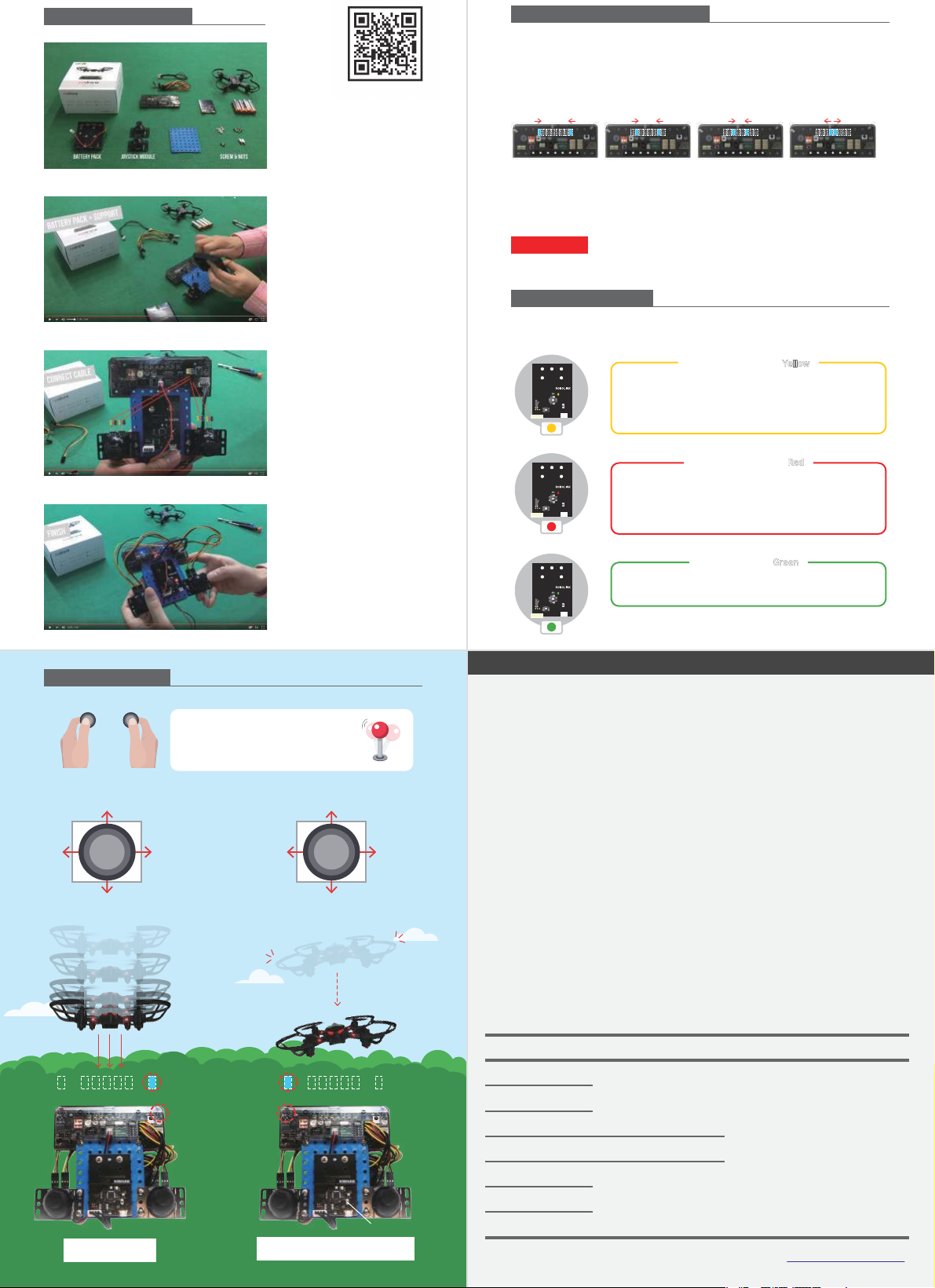
※ Yellow : Communicat ion mode / Red : Blue tooth mode
Connec t the PC to BLE b oard with a Mic ro-5-pin Ca ble.
Press t he switch on th e BLE board to c hange the color o f
LED to
red.
Install - USB Driver
Warning!
Step 4. Take off / Landing
Drone Sim ulator
Take off : Press W key
!
Once : La nding
Twice :
Emergency
Stop
Rememb er how to
initia te an
emergency
stop
before f light!
Turn
left
DownTurn
Right
Up
Move up / do wn
Turn left / r ight
LeftBackwardRight
Forward
Move Fo rward /
Back ward / Lef t / Right
Through Smart Inven tor
Board
, you can pr ogram the
device w ith connec tions of
joysti ck, analog se nsors,
and digit al sensors.
What do I need ?
PC, BL E
What do I need ?
Rokit BRI CK is based on
Scratc h. Beginn ers can use
a drag & dro p Scratch- like
GUI.
What do I need ?
It is the pe rfect tool f or
beginne rs. You can easil y
control drone, record the
flight pa ttern, trim , and
more.
What do I need ?
Use your sm artphone to
control t he drone and dr ive
kit or FP V (first-pers on
view) ki t.
Software
LEARN TO
CODE
SMART
INVENTOR BOARD
MOBILE APPPC SOF TWA RE
Check with the video
http://robolink.co.kr
/sw/codrone
/01_codrone.html
CoDrone page
http://robolink.co.kr
/download_jp.html
Download (JPN)
Inser t the batter y
bli
n
k
b
li
n
k
Searc hing for signal (b linking)
d
i
n
g!
Connected (solid)
CoDrone Warranty
2) Assemble a controller wi th
components .
3) Connect the b oard and cable,
while paying attent ion on color
alignments.
4) Power o n the Inventor Board an d
CoDro ne, then pair both.
▶ Refer “Connec t to Inventor Bo ard”
on the right.
1) Check if all component s
are prepared.
1. Turn on CoDrone ’s power.
2. Turn on Smar t Inventor Boa rd’s power.
3. Wait for t heir connect ions.
4. LED lights on S mart Inventor Board flicker back an d forth by its
center. (meaning it is searching t he device near by)
5. BLE B oard’s LED lig ht changes to green.
(meaning i ts successful conn ection)
6. CoDr one’s LED stops blinking. (meanin g its success ful connect ion)
7. All pairing proces ses complete.
Warning
If CoDrone’s unexpectedly powers of f or pairing fails, repeat theprocedures 1~7 above.
Landing
Button
The rightmost
sensor
The leftmost
sensor
feet
Emergency Stop
*In cases of em ergency, pres s BLE Board ’s
switch twice in a row. T he drone will s top
Control the drone with
the assembled joystick
Up
Down
Tur n
Left
Tur n
Right
Forward
Backward
LeftRight
Connect to Inventor Board
Depending on LED color on BLE Board, act correspondingly by knowing whateach color
symbolizes. (
Purple : Operating)
BLE Board Status
Build it - Assemble
Youtube Link
https://youtu.be
/nwFUgs5sKpc
Play it - Control
Visit us www.robolink.co.kr
Copyr ight 2017ⓒ Robolin k All rights r eserved .
Quality Certificate
This certificate ensures protecting rights of consumers who bought CoDrone
Package. Our company will provide paid/free service to our customers, as in
the following details.
1. Warranty Details : Robolink will conduct following guarantees, under the
provision of Consumer Compensation Rules by Item. If manufactural defect
or spontaneous failure occurs before the expiration of the term of guarantee,
you are qualified to receive free services from us.
2. Term of Guarantee : Up to 1 year since the purchase date (Each component
in this package has different policies; read the Range of Assurance below)
3. Determination of Assurance : Will be determined after consultations by
telephone or online services, or by direct discussion in exhibitions.
4. Range of Assurance (Refer the table below)
Component
CoDrone’s Mainboard
Smart Inventor Board
Charger
Battery
Propellers
Propeller’s Guard
Propeller Motors
Term of Guarantee
1 year since
the purc hase
Not applied
2 month s since the purc hase
Guarantee Exclusions
1. Simply b ecause cons umers’chan ge of
mind
2. Maint enance/Rep air of devices a fter
term of gu arantee
3. Failur e or damage cau sed by custo mers’
misuse o r mistake
4. Failur e not caused f rom the devi ce itself
5. Arb itrary di smantle or ac tion taken by
custo mers
6. Prob lems cause d by product s from
other co mpanies
Pairin g Standby Mode Red
Use this mode when you pair your C oDrone and BL E Board. In
Commun ication Mod e, press the button on ce to switch into this
mode. P ress the but ton for more than 5 s econds to make this
mode ap pear first, inste ad of Communication M ode.
This mo de appears first when you co nnect its power. If the b oard
is in Pair ing Standby Mo de (Red), press i ts button on ce to change
into Communication M ode. In this mod e, upload your A rduino file
or connect Rokit Simulator to the boa rd.
Communication Mode Yellow
This means the B LE board completed its pairing w ith Inventor
Board.
Pairin g Complete Green
 Loading...