


ROBO Cylinder
RCP6/RCP6S Actuator
Rod Type
Instruction Manual
Second edition
Motor Straight Type:
RA4C, RA6C, RA7C, RA8C
Side-Mounted Motor Type:
RA4R, RA6R, RA7R, RA8R
IAI America, Inc.


Please Read Before Use
Thank you for purchasing our product.
This instruction manual explains the handling methods, structure and maintenance of this
product, among others, providing the information you need to know to use the product
safely.
Before using the product, be sure to read this manual and fully understand the contents
explained herein to ensure safe use of the product.
The DVD that comes with the product contains instruction manuals for IAI products.
When using the product, refer to the necessary portions of the applicable instruction manual
by printing them out or displaying them on a PC.
After reading the instruction manual, keep it in a convenient place so that whoever is
handling this product can reference it quickly when necessary.
[Important]
• This instruction manual is original.
• This product is not to be used for any other purpose from what is noted in this instruction
manual. IAI shall not be liable whatsoever for any loss or damage arising from the result of
using the product for any other purpose from what is noted in the manual.
• The information contained in this instruction manual is subject to change without notice for
the purpose of production improvement.
• If you have any question or finding regarding the information contained in this instruction
manual, contact our customer center or our sales office near you.
• Using or copying all or a part of this instruction manual without permission is prohibited.
• The company names, names of products and trademarks of each company shown in the
sentences are registered trademarks.

Description of RCP6S controller unit is not included in this instruction manual.
With regard to RCP6S controller unit, refer to the separate instruction manual.

Table of Contents
Safety Guide...................................................................................................................................2
Caution in Handling ........................................................................................................................9
International Standards Compliances ...........................................................................................10
Names of the Parts ....................................................................................................................... 11
1.
Specifications Check...................................................................................................................... 17
1.1 Checking the Product................................................................................................................. 17
1.1.1 Parts ............................................................................................................................... 17
1.1.2 Related Instruction Manuals for the Each Controller Supported by This Product.......... 18
1.1.3 How to Read the Model Nameplate ............................................................................... 18
1.2 Specifications ............................................................................................................................. 20
1.2.1 Speed.............................................................................................................................. 20
1.2.3 Driving System • Position Detector................................................................................. 47
1.2.4 Positioning Precision ...................................................................................................... 47
1.2.5 Rod Tip Load .................................................................................................................. 47
1.2.6 Current Limit Value and Pressing Force......................................................................... 48
1.2.7 Rod Tip Inclination Amount (reference).......................................................................... 52
1.2.8 Duty Ratio for Continuous Operation ............................................................................. 54
1.3 Options....................................................................................................................................... 55
1.3.1 Brake Type (Model: B).................................................................................................... 55
1.3.2 Reversed-home Specification (Model: NM).................................................................... 55
1.3.3 Flange Bracket (Front) (Model: FL) ................................................................................ 55
1.3.4 Foot Bracket (Model: FT)................................................................................................ 56
1.3.5 T-slot Nut Bar (Model: NTB) ........................................................................................... 56
1.3.6 Tip Adapter (Internal Thread) (Model: NFA) ................................................................... 57
1.3.7 Motor Left Side-Mounted, Motor Top Side-Mounted, Motor Right Side-Mounted
(Model: ML, MT, MR) ..................................................................................................................... 59
1.3.8 Cable Exit Direction Changed (Model: CJT, CJR, CJL, CJB, CJO) ............................... 59
1.4 Motor • Encoder Cables ............................................................................................................. 60
1.4.1 Motor • Encoder Integrated Cables (RA4, RA6 and RA7).............................................. 60
1.4.2 Motor • Encoder Integrated Cables Robot Type (RA4, RA6 and RA7) .......................... 61
1.4.3 Motor • Encoder Integrated Cables (RA8)...................................................................... 62
1.4.4 Motor • Encoder Integrated Cables (RA8)...................................................................... 63
2. Installation ...................................................................................................................................... 64

2.1 Transportation ............................................................................................................................ 64
2.2 Installation and Storage • Preservation Environment ................................................................ 66
2.3 How to Install.............................................................................................................................. 67
2.3.1 Installation....................................................................................................................... 67
2.3.2 Installation of the Main Unit ............................................................................................ 68
3. Connecting with the Controller....................................................................................................... 86
4. Caution for Operation..................................................................................................................... 90
5. Maintenance and Inspection .......................................................................................................... 91
5.1 Inspection Items and Schedule.................................................................................................. 91
5.2 External Visual Inspection.......................................................................................................... 92
5.3 Cleaning ..................................................................................................................................... 92
5.4 Grease Supply ........................................................................................................................... 92
5.4.1 What Grease to Use ....................................................................................................... 92
5.4.2 How to Apply Grease...................................................................................................... 93
5.5 Procedure for Belt Replacement and Tuning............................................................................. 94
5.5.1 Inspection of the Belt ...................................................................................................... 94
5.5.2 Belt to Use ...................................................................................................................... 94
5.5.3 Belt Replacement ........................................................................................................... 95
5.6 Motor Replacement Process...................................................................................................... 99
5.6.1 RA4C, RA6C, RA7C....................................................................................................... 99
5.6.2 RA8C ............................................................................................................................ 101
5.6.3 RA4R, RA6R, RA7R, RA8R ......................................................................................... 104
6. External Dimensions .....................................................................................................................111
6.1 Standard Specification RCP6-RA4C......................................................................................... 111
6.2 Built-in Controller Specification RCP6S-RA4C .........................................................................112
6.3 Standard Specification RCP6-RA6C.........................................................................................113
6.4 Built-in Controller Specification RCP6S-RA6C .........................................................................114
6.5 Standard Specification RCP6-RA7C.........................................................................................115
6.6 Built-in Controller Specification RCP6S-RA7C .........................................................................116
6.7 Standard Specification RCP6-RA8C.........................................................................................117
6.8 Built-in Controller Specification RCP6S-RA8C .........................................................................118
6.9 Standard Specification RCP6-RA4R Top Side-Mounted (Model: MT) ......................................119
6.10 Standard Specification RCP6-RA4R Left Side-Mounted (Model: ML) ................................... 120
6.11 Built-in Controller Specification RCP6S-RA4R Top Side-Mounted (Model: MT) ................... 121
6.12 Built-in Controller Specification RCP6S-RA4R Left Side-Mounted (Model: ML) ................... 122
6.13 Standard Specification RCP6-RA6R Top Side-Mounted (Model: MT) ................................... 123

6.14 Standard Specification RCP6-RA6R Left Side-Mounted (Model: ML) ................................... 124
6.15 Built-in Controller Specification RCP6S-RA6R Top Side-Mounted (Model: MT) ................... 125
6.16 Built-in Controller Specification RCP6S-RA6R Left Side-Mounted (Model: ML) ................... 126
6.17 Standard Specification RCP6-RA7R Top Side-Mounted (Model: MT) ................................... 127
6.18 Standard Specification RCP6-RA7R Left Side-Mounted (Model: ML) ................................... 128
6.19 Built-in Controller Specification RCP6S-RA7R Top Side-Mounted (Model: MT) ................... 129
6.20 Built-in Controller Specification RCP6S-RA7R Left Side-Mounted (Model: ML) ................... 130
6.21 Standard Specification RCP6-RA8R Top Side-Mounted (Model: MT) ................................... 131
6.22 Standard Specification RCP6-RA8R Left Side-Mounted (Model: ML) ................................... 132
6.23 Built-in Controller Specification RCP6S-RA8R Top Side-Mounted (Model: MT) ................... 133
6.24 Standard Specification RCP6S-RA8R Left Side-Mounted (Model: ML)................................. 134
7. Life................................................................................................................................................ 135
7.1 RA4C, RA4R, RA6C, RA6R, RA7C, RA7R ............................................................................. 135
7.2 RA8C, RA8R ............................................................................................................................ 135
8. Warranty....................................................................................................................................... 136
8.1 Warranty Period ....................................................................................................................... 136
8.2 Scope of the Warranty ............................................................................................................. 136
8.3 Honoring the Warranty............................................................................................................. 136
8.4 Limited Liability ........................................................................................................................ 137
8.5
Conditions of Conformance with Applicable Standards/Regulations, Etc., and Applications
.... 137
8.6 Other Items Excluded from Warranty....................................................................................... 137
Change History.................................................................................................................................... 138

1

2
Safety Guide
“Safety Guide” has been written to use the machine safely and so prevent personal injury or property
damage beforehand. Make sure to read it before the operation of this product.
Safety Precautions for Our Products
The common safety precautions for the use of any of our robots in each operation.
No.
Operation
Description
Description
1 Model
Selection
● This product has not been planned and designed for the application
where high level of safety is required, so the guarantee of the protection
of human life is impossible. Accordingly, do not use it in any of the
following applications.
1) Medical equipment used to maintain, control or otherwise affect
human life or physical health.
2) Mechanisms and machinery designed for the purpose of moving or
transporting people (For vehicle, railway facility or air navigation
facility)
3) Important safety parts of machinery (Safety device, etc.)
● Do not use the product outside the specifications. Failure to do so may
considerably shorten the life of the product.
● Do not use it in any of the following environments.
1) Location where there is any inflammable gas, inflammable object or
explosive
2) Place with potential exposure to radiation
3) Location with the ambient temperature or relative humidity exceeding
the specification range
4) Location where radiant heat is added from direct sunlight or other
large heat source
5) Location where condensation occurs due to abrupt temperature
changes
6) Location where there is any corrosive gas (sulfuric acid or
hydrochloric acid)
7) Location exposed to significant amount of dust, salt or iron powder
8) Location subject to direct vibration or impact
● For an actuator used in vertical orientation, select a model which is
equipped with a brake. If selecting a model with no brake, the moving
part may drop when the power is turned OFF and may cause an
accident such as an injury or damage on the work piece.

3
No.
Operation
Description
Description
2 Transportation
● When carrying a heavy object, do the work with two or more persons or
utilize equipment such as crane.
● When the work is carried out with 2 or more persons, make it clear who
is to be the leader and who to be the follower(s) and communicate well
with each other to ensure the safety of the workers.
● When in transportation, consider well about the positions to hold, weight
and weight balance and pay special attention to the carried object so it
would not get hit or dropped.
● Transport it using an appropriate transportation measure.
The actuators available for transportation with a crane have eyebolts
attached or there are tapped holes to attach bolts. Follow the
instructions in the instruction manual for each model.
● Do not step or sit on the package.
● Do not put any heavy thing that can deform the package, on it.
● When using a crane capable of 1t or more of weight, have an operator
who has qualifications for crane operation and sling work.
● When using a crane or equivalent equipments, make sure not to hang a
load that weighs more than the equipment's capability limit.
● Use a hook that is suitable for the load. Consider the safety factor of the
hook in such factors as shear strength.
● Do not get on the load that is hung on a crane.
● Do not leave a load hung up with a crane.
● Do not stand under the load that is hung up with a crane.
3 Storage and
Preservation
● The storage and preservation environment conforms to the installation
environment. However, especially give consideration to the prevention
of condensation.
● Store the products with a consideration not to fall them over or drop due
to an act of God such as earthquake.
4 Installation
and Start
(1) Installation of Robot Main Body and Controller, etc.
● Make sure to securely hold and fix the product (including the work part).
A fall, drop or abnormal motion of the product may cause a damage or
injury.
Also, be equipped for a fall-over or drop due to an act of God such as
earthquake.
● Do not get on or put anything on the product. Failure to do so may cause
an accidental fall, injury or damage to the product due to a drop of
anything, malfunction of the product, performance degradation, or
shortening of its life.
● When using the product in any of the places specified below, provide a
sufficient shield.
1) Location where electric noise is generated
2) Location where high electrical or magnetic field is present
3) Location with the mains or power lines passing nearby
4) Location where the product may come in contact with water, oil or
chemical droplets

4
No.
Operation
Description
Description
4 Installation
and Start
(2) Cable Wiring
● Use our company’s genuine cables for connecting between the actuator
and controller, and for the teaching tool.
● Do not scratch on the cable. Do not bend it forcibly. Do not pull it. Do not
coil it around. Do not insert it. Do not put any heavy thing on it. Failure to
do so may cause a fire, electric shock or malfunction due to leakage or
continuity error.
● Perform the wiring for the product, after turning OFF the power to the
unit, so that there is no wiring error.
● When the direct current power (+24V) is connected, take the great care
of the directions of positive and negative poles.
If the connection direction is not correct, it might cause a fire, product
breakdown or malfunction.
● Connect the cable connector securely so that there is no disconnection
or looseness. Failure to do so may cause a fire, electric shock or
malfunction of the product.
● Never cut and/or reconnect the cables supplied with the product for the
purpose of extending or shortening the cable length. Failure to do so
may cause the product to malfunction or cause fire.
(3) Grounding
● The grounding operation should be performed to prevent an electric
shock or electrostatic charge, enhance the noise-resistance ability and
control the unnecessary electromagnetic radiation.
● For the ground terminal on the AC power cable of the controller and the
grounding plate in the control panel, make sure to use a twisted pair
cable with wire thickness 0.5mm
2
(AWG20 or equivalent) or more for
grounding work. For security grounding, it is necessary to select an
appropriate wire thickness suitable for the load. Perform wiring that
satisfies the specifications (electrical equipment technical standards).
● Perform Class D Grounding (former Class 3 Grounding with ground
resistance 100Ω or below).

5
No.
Operation
Description
Description
4 Installation
and Start
(4) Safety Measures
● When the work is carried out with 2 or more persons, make it clear who
is to be the leader and who to be the follower(s) and communicate well
with each other to ensure the safety of the workers.
● When the product is under operation or in the ready mode, take the
safety measures (such as the installation of safety and protection fence)
so that nobody can enter the area within the robot's movable range.
When the robot under operation is touched, it may result in death or
serious injury.
● Make sure to install the emergency stop circuit so that the unit can be
stopped immediately in an emergency during the unit operation.
● Take the safety measure not to start up the unit only with the power
turning ON. Failure to do so may start up the machine suddenly and
cause an injury or damage to the product.
● Take the safety measure not to start up the machine only with the
emergency stop cancellation or recovery after the power failure. Failure
to do so may result in an electric shock or injury due to unexpected
power input.
● When the installation or adjustment operation is to be performed, give
clear warnings such as “Under Operation; Do not turn ON the power!”
etc. Sudden power input may cause an electric shock or injury.
● Take the measure so that the work part is not dropped in power failure or
emergency stop.
● Wear protection gloves, goggle or safety shoes, as necessary, to secure
safety.
● Do not insert a finger or object in the openings in the product. Failure to
do so may cause an injury, electric shock, damage to the product or fire.
● When releasing the brake on a vertically oriented actuator, exercise
precaution not to pinch your hand or damage the work parts with the
actuator dropped by gravity.
5 Teaching
● When the work is carried out with 2 or more persons, make it clear who
is to be the leader and who to be the follower(s) and communicate well
with each other to ensure the safety of the workers.
● Perform the teaching operation from outside the safety protection fence,
if possible. In the case that the operation is to be performed unavoidably
inside the safety protection fence, prepare the “Stipulations for the
Operation” and make sure that all the workers acknowledge and
understand them well.
● When the operation is to be performed inside the safety protection fence,
the worker should have an emergency stop switch at hand with him so
that the unit can be stopped any time in an emergency.
● When the operation is to be performed inside the safety protection fence,
in addition to the workers, arrange a watchman so that the machine can
be stopped any time in an emergency. Also, keep watch on the
operation so that any third person can not operate the switches
carelessly.
● Place a sign “Under Operation” at the position easy to see.
● When releasing the brake on a vertically oriented actuator, exercise
precaution not to pinch your hand or damage the work parts with the
actuator dropped by gravity.
* Safety protection Fence : In the case that there is no safety protection
fence, the movable range should be indicated.

6
No.
Operation
Description
Description
6 Trial
Operation
● When the work is carried out with 2 or more persons, make it clear who
is to be the leader and who to be the follower(s) and communicate well
with each other to ensure the safety of the workers.
● After the teaching or programming operation, perform the check
operation one step by one step and then shift to the automatic operation.
● When the check operation is to be performed inside the safety protection
fence, perform the check operation using the previously specified work
procedure like the teaching operation.
● Make sure to perform the programmed operation check at the safety
speed. Failure to do so may result in an accident due to unexpected
motion caused by a program error, etc.
● Do not touch the terminal block or any of the various setting switches in
the power ON mode. Failure to do so may result in an electric shock or
malfunction.
7 Automatic
Operation
● Check before starting the automatic operation or rebooting after
operation stop that there is nobody in the safety protection fence.
● Before starting automatic operation, make sure that all peripheral
equipment is in an automatic-operation-ready state and there is no
alarm indication.
● Make sure to operate automatic operation start from outside of the safety
protection fence.
● In the case that there is any abnormal heating, smoke, offensive smell,
or abnormal noise in the product, immediately stop the machine and turn
OFF the power switch. Failure to do so may result in a fire or damage to
the product.
● When a power failure occurs, turn OFF the power switch. Failure to do
so may cause an injury or damage to the product, due to a sudden
motion of the product in the recovery operation from the power failure.

7
No.
Operation
Description
Description
8 Maintenance
and
Inspection
● When the work is carried out with 2 or more persons, make it clear who
is to be the leader and who to be the follower(s) and communicate well
with each other to ensure the safety of the workers.
● Perform the work out of the safety protection fence, if possible. In the
case that the operation is to be performed unavoidably inside the safety
protection fence, prepare the “Stipulations for the Operation” and make
sure that all the workers acknowledge and understand them well.
● When the work is to be performed inside the safety protection fence,
basically turn OFF the power switch.
● When the operation is to be performed inside the safety protection fence,
the worker should have an emergency stop switch at hand with him so
that the unit can be stopped any time in an emergency.
● When the operation is to be performed inside the safety protection fence,
in addition to the workers, arrange a watchman so that the machine can
be stopped any time in an emergency. Also, keep watch on the operation
so that any third person can not operate the switches carelessly.
● Place a sign “Under Operation” at the position easy to see.
● For the grease for the guide or ball screw, use appropriate grease
according to the instruction manual for each model.
● Do not perform the dielectric strength test. Failure to do so may result in
a damage to the product.
● When releasing the brake on a vertically oriented actuator, exercise
precaution not to pinch your hand or damage the work parts with the
actuator dropped by gravity.
● The slider or rod may get misaligned OFF the stop position if the servo is
turned OFF. Be careful not to get injured or damaged due to an
unnecessary operation.
● Pay attention not to lose the cover or untightened screws, and make
sure to put the product back to the original condition after maintenance
and inspection works.
Use in incomplete condition may cause damage to the product or an
injury.
* Safety protection Fence : In the case that there is no safety protection
fence, the movable range should be indicated.
9 Modification
and Dismantle
● Do not modify, disassemble, assemble or use of maintenance parts not
specified based at your own discretion.
10 Disposal
● When the product becomes no longer usable or necessary, dispose of it
properly as an industrial waste.
● When removing the actuator for disposal, pay attention to drop of
components when detaching screws.
● Do not put the product in a fire when disposing of it. The product may
burst or generate toxic gases.
11 Other
● Do not come close to the product or the harnesses if you are a person
who requires a support of medical devices such as a pacemaker. Doing
so may affect the performance of your medical device.
● See Overseas Specifications Compliance Manual to check whether
complies if necessary.
● For the handling of actuators and controllers, follow the dedicated
instruction manual of each unit to ensure the safety.

8
Alert Indication
The safety precautions are divided into “Danger”, “Warning”, “Caution” and “Notice” according to the
warning level, as follows, and described in the instruction manual for each model.
Level Degree of Danger and Damage Symbol
Danger
This indicates an imminently hazardous situation which, if the product
is not handled correctly, will result in death or serious injury.
Danger
Warning
This indicates a potentially hazardous situation which, if the product
is not handled correctly, could result in death or serious injury.
Warning
Caution
This indicates a potentially hazardous situation which, if the product
is not handled correctly, may result in minor injury or property
damage.
Caution
Notice
This indicates lower possibility for the injury, but should be kept to
use this product properly.
Notice

9
Caution in Handling
1. Make sure to follow the usage condition, environment and specification
range of the product.
In case it is not secured, it may cause a drop in performance or malfunction of the product.
2. Do not attempt to have any handling or operation that is not stated in this
Instruction manual.
3. It is recommended to apply our products for the wiring between the actuator
and the controller.
4. Do not attempt to establish the settings for the speed and
acceleration/deceleration above the allowable range.
An operation with speed and acceleration/deceleration beyond the allowable range may cause an
abnormal noise, vibration, malfunction or shortened life.
5. Do not apply radial load and load moment to the rod.
Loads can only be applied in the axial direction matching with the rod axis.
6. If back and forth operations are performed repeatedly in short distance, it
may wear out the film of grease.
Continuous back and forth operation within a distance less than 30mm may cause wear of grease.
As a reference, have approximately 5 cycles of back and forth operation in a distance more than 50mm in
every 5,000 to 10,000 cycles to regenerate the oil film. Keep using the actuator with the grease worn out
may cause malfunction. If it is extreme, flaking may occur on the guide, ball screw.
7. Do not attempt to hit the rod against an abstacle with high speed.
It may destroy the coupling.
8. Make sure to attach the actuator properly by following this instruction
manual.
Using the product with the actuator not being certainly retained or affixed may cause abnormal noise,
vibration, malfunction or shorten the product life.
9. Grease has been applied to the outer periphery of the rod. Protect the
peripheral equipments if grease adhesion affects them.

10
10. For PCON-CB and MCON Controllers (with option: T), it is available to
switch over the setting between effective and ineffective of the high-output
setting in the parameter setting.
(In the setting at delivery, the high output setting is set to effective.)
For MSEL Controller, the high output setting is effective and cannot switch it over to ineffective.
[Refer to an instruction manual for each controller for details]
The performance of weight capacity at each velocity and acceleration/deceleration setting differs
between the high output setting being effective and ineffective. Refer to the applicable
performance specification when the high-output setting is effective or ineffective in 1.2
Specifications.
Controller Parameter Remarks
PCON-CB No.152 High Output Setting
[0: Ineffective, 1: Effective]
MCON No.152 High Output Setting
[0: Ineffective, 1: Effective]
Option T: In high output setting, available to
have high output setting effective.
International Standards Compliances
This actuator complies with the following overseas standard.
Refer to Overseas Standard Compliance Manual (ME0287) for more detailed information.
RoHS Directive CE Marking
○ ○

11
Names of the Parts
In this Instruction Manual, the left and right sides are indicated by looking at the actuator from the motor
end, with the actuator placed horizontally, as shown in the figure below.
1. Straight Type
1.1 Standard Specification RCP6-RA4C
1.2 Built-in Controller Specification RCP6S-RA4C
Rod
Rod Tip Adaptor
Motor Unit
Screw for Motor Unit Attachment
Grease Supply (Φ2.5 hole)
(Hexagonal Socket Head Bolt)
Grease Supply (Φ2.5 hole)
(Hexagonal Socket Head Bolt)
(The same applies to the other side)
Body Frame
Bearing
Tapped Hole for
Ground Cable
Connection
Connector
Rod Tip Adaptor
Rod
Motor Side
Right Side
Opposite Side
Left Side
Opposite Side Motor Side
Left Side
Right Side
Teaching Port
Status LED
Screw for Motor Unit Attachment
Motor Unit
Grease Supply (Φ2.5 hole)
(Hexagonal Socket Head Bolt)
Grease Supply (Φ2.5 hole)
(Hexagonal Socket Head Bolt)
(The same applies to the other side)
Body Frame
Bearing
Tapped Hole for
Ground Cable
Connection
Power · I/O Cable
Connector

12
1.3 Standard Specification RCP6-RA6C, RA7C
1.4 Built-in Controller Specification RCP6S-RA6C, RA7C
Rod
Rod Tip Adapto
r
Body Frame
Bearing
Grease Supply (Φ5 hole)
(Rubber Cap)
(The same applies to the other side)
Grease Supply (Φ5 hole)
(Rubber Cap)
Motor Unit
Screw for Motor Unit Attachment
Tapped Hole for
Ground Cable
Connection
Connector
Rod
Rod Tip Adapto
r
Grease Supply (Φ5 hole)
(Rubber Cap)
(The same applies to the other side)
Grease Supply (Φ5 hole)
(Rubber Cap)
Body Frame
Screw for Motor Unit Attachment
Motor Unit
Tapped Hole for
Ground Cable
Connection
Teaching Port
Bearing
Status LED
Power · I/O Cable
Connector
Motor Side
Right Side
Opposite Side
Left Side
Motor Side
Right Side
Opposite Side
Left Side

13
1.5 Standard Specification RCP6-RA8C
1.6 Built-in Controller Specification RCP6S-RA8C
Rod
Rod Tip Adaptor
Grease Supply (Φ5 hole)
(Rubber Cap)
(The same applies to the other side)
Grease Supply (Φ5 hole)
(Rubber Cap)
Body Frame
Motor Cover
End Cover
Tapped Hole for
Ground Cable
Connection
Teaching Port
Bearing
Status LED
Power · I/O Cable
Connector
Rod
Rod Tip Adaptor
Grease Supply (Φ5 hole)
(Rubber Cap)
(The same applies to the other side)
Grease Supply (Φ5 hole)
(Rubber Cap)
Body Frame
Motor Cover
End Cove
r
Tapped Hole for
Ground Cable
Connection
Bearing
Connector
Motor Side
Right Side
Opposite Side
Left Side
Motor Side
Right Side
Opposite Side
Left Side

14
2. Side-Mounted Motor Type
2.1 Standard Specification RCP6-RA4R
2.2 Built-in Controller Specification RCP6S-RA4R
Rod
Rod Tip Adaptor
Grease Supply (Φ2.5 hole)
(Hexagonal Socket Head Bolt)
(The same applies to the other side)
Body Frame
Motor Cover
End Cover
Pulley Cover
Bearing
Tapped Hole for Ground
Cable Connection
Rear Bracket
Connector
Rod
Rod Tip Adaptor
Grease Supply (Φ2.5 hole)
(Hexagonal Socket Head Bolt)
(The same applies to the other side)
Body Frame
Motor Cover
End Cover
Pulley Cover
Bearing
Tapped Hole for Ground
Cable Connection
Rear Bracket
Status LED
Teaching Port
Power · I/O Cable
Connector
Motor Side
Right Side
Opposite Side
Left Side
Motor Side
Right Side
Opposite Side
Left Side

15
2.3 Standard Specification RCP6-RA6R, RA7R
2.4 Built-in Controller Specification RCP6S-RA6R, RA7R
Rod
Rod Tip Adaptor
Grease Supply (Φ5 hole)
(Hexagonal Socket Head Bolt)
(The same applies to the other side)
Body Frame
Motor Cover
End Cover
Pulley Cover
Bearing
Tapped Hole for Ground
Cable Connection
Rear Bracket
Connector
Rod
Rod Tip Adaptor
Grease Supply (Φ5 hole)
(Hexagonal Socket Head Bolt)
(The same applies to the other side)
Body Frame
Motor Cover
End Cover
Pulley Cover
Bearing
Tapped Hole for Ground
Cable Connection
Rear Bracket
Teaching Port
Status LED
Power · I/O Cable
Connector
Motor Side
Right Side
Opposite Side
Left Side
Motor Side
Right Side
Opposite Side
Left Side

16
2.5 Standard Specification RCP6-RA8R
2.6 Built-in Controller Specification RCP6S-RA8R
Rod
Rod Tip Adaptor
Grease Supply (Φ5 hole)
(Hexagonal Socket Head Bolt)
(The same applies to the other side)
Body Frame
Motor Cover
End Cover
Pulley Cover
Bearing
Tapped Hole for Ground
Cable Connection
Rear Bracket
Connector
Rod
Rod Tip Adaptor
Grease Supply (Φ5 hole)
(Hexagonal Socket Head Bolt)
(The same applies to the other side)
Body Frame
Motor Cover
End Cover
Pulley Cover
Bearing
Tapped Hole for Ground
Cable Connection
Rear Bracket
Power · I/O Cable
Connector
Teaching Port
Status LED
Motor Side
Right Side
Opposite Side
Left Side
Motor Side
Right Side
Opposite Side
Left Side

17
1. Specifications Check
1. Specifications Check
1.1 Checking the Product
The standard configuration of this product is comprised of the following parts.
See the component list for the details of the enclosed components. If you find any fault or missing
parts, contact your local IAI distributor.
1.1.1 Parts
No. Name Model number Quantity Remarks
1 Actuator
Refer to “How to
Read the Model
Nameplate” and
“How to Read the
Model Number.”
1
Accessories
2 Motor • Encoder Cables
(Note1)
1
3 Nut 1 Refer to list below
4 Square T-nut 1 set Refer to list below
5 First Step Guide 1
6 Instruction Manual (DVD) 1
7 Safety Guide 1
Note 1 The motor • encoder cables supplied vary depending on the controller used. [Refer to 1.4,
“Motor • Encoder Cables.”]
[List of Included Nut Type]
Nut (M10×1.25) Nut (M14×1.5) Nut (M20×1.5)
RA4C, RA4R
RA6C, RA6R
1
RA7C, RA7R 1
RA8C, RA8R 1
[Refer to 6. “External Dimensions” for the dimensions of nuts.]
[List of Included Square T-nut Type]
Square T-nut Quantity
RA4C, RA4R M4 □7×3.2 4
RA6C, RA6R M6 □10×5 4
RA7C, RA7R M6 □10×5 8
RA8C, RA8R M8 □13×6.5 8

18
1. Specifications Check
1.1.2 Related Instruction Manuals for the Each Controller Supported by This
Product
Shown below is a list of the instruction manuals for the controllers related to this product which is
recorded in Instruction Manual (DVD).
No. Name Control No.
1 Instruction Manual for PCON-CB/CFB Controller ME0342
2 Instruction Manual for MCON-C/CG Controller ME0341
3 Instruction Manual for MSEL Controller ME0336
4
Instruction Manual for RC PC Software
RCM-101-MW/RCM-101-USB
ME0155
5
Instruction Manual for Touch Panel Teaching Pendant
CON-PTA/PDA/PGA
ME0295
6
Instruction Manual for Touch Panel Teaching Pendant
TB-01/01D/01DR
Applicable for Position Controller
ME0324
1.1.3 How to Read the Model Nameplate
Model
MODEL RCP6-RA4C-WA-35P-2.5-50-P3-P-B
SERIAL No.100090267 MADE IN JAPAN
Serial number

19
1. Specifications Check
1.1.4 How to Read the Model Number
RCP6-RA4C-WA-35P-2.5-50-P3-P-B-**
Note 1 Identification for IAI use only: It may be displayed for IAI use. It is not a code to show the model
type.
<Series name>
Standard Specification
RCP6
Built-in Controller Specification
RCP6S
<Type>
Motor straight type
RA4C
RA6C
RA7C
RA8C
Side-Mounted Motor
Type
RA4R
RA6R
RA7R
RA8R
<Encoder type>
WA : Battery-less
absolute
<Motor type>
35P: 35□size
42P: 42□size
56P: 56□size
60P: 60□size
<Lead>
RA4C, RA4R
2.5/5/10/16
RA6C, RA6R
3/6/12/20
RA7C, RA7R
4/8/16/24
RA8C, RA8R
5/10/20
<Options>
B : Brake
NM : Reversed-home
specification
FL : Flange bracket
FT : Foot bracket
NTB : T-slot nut bar specification
NFA : Tip adapter (Internal
Thread)
ML : Motor left side-mounted
MR : Motor right side-mounted
MT : Motor top side-mounted
CJT : Cable exit direction
changed (Top)
CJR : Cable exit direction
changed (Right)
CJL : Cable exit direction
changed (Left)
CJB : Cable exit direction
changed (Bottom)
CJO : Cable exit direction
changed (Outward)
<Cable length>
N : None
P : 1m
S : 3m
M : 5m
X : Length specification
R : Robot cable
Standard Specification
<Controller>
P3: PCON-CB
MCON
MSEL
P4: PCON-CFB
Built-in Controller Specification
<I/O Type>
SE: SIO type
<Stroke>
[Refer to 1.2 “Specifications”]
Identification for IAI use
only
(Note1)

20
1. Specifications Check
1.2 Specifications
1.2.1 Speed
[1] Motor Straight Type
[When high-output setting is effective]
Speed limits [Unit: mm/s]
Stroke [mm]
Size
Motor
Type
Lead
[mm]
Horizontal/
Vertical
50 100 150 200 - -
Horizontal 175 - -
2.5
Vertical 175 - -
Horizontal 350 - -
5
Vertical 350 - -
Horizontal 700 - -
10
Vertical 700 - -
Horizontal 840 - -
RA4C 35P
16
Vertical 840 - -
50 100 150 200 250 300
Horizontal 225
3
Vertical 225
Horizontal 450
6
Vertical 450
Horizontal 700
12
Vertical 700
Horizontal 800
RA6C 42P
20
Vertical 800
50 100 150 200 250 300
Horizontal 210
4
Vertical 175
Horizontal 420
8
Vertical 350
Horizontal 700
16
Vertical 560
Horizontal 860
RA7C 56P
24
Vertical 640
50 100 150 200 250 300
Horizontal 150
5
Vertical 150
Horizontal 300
10
Vertical 250
Horizontal 600
RA8C 60P
20
Vertical 450

21
1. Specifications Check
[2] Side-Mounted Motor Type
[When high-output setting is effective]
Speed limits [Unit: mm/s]
Stroke [mm]
Size
Motor
Type
Lead
[mm]
Horizontal/
Vertical
50 100 150 200 - -
Horizontal 175 - -
2.5
Vertical 175 - -
Horizontal 350 - -
5
Vertical 350 - -
Horizontal 610 - -
10
Vertical 610 - -
Horizontal 840 - -
RA4R 35P
16
Vertical 840 - -
50 100 150 200 250 300
Horizontal 225
3
Vertical 225
Horizontal 450
6
Vertical 450
Horizontal 700
12
Vertical 700
Horizontal 800
RA6R 42P
20
Vertical 800
50 100 150 200 250 300
Horizontal 175
4
Vertical 175
Horizontal 420
8
Vertical 350
Horizontal 560
16
Vertical 560
Horizontal 800
RA7R 56P
24
Vertical 640
50 100 150 200 250 300
Horizontal 100
5
Vertical 100
Horizontal 200
10
Vertical 200
Horizontal 400
RA8R 60P
20
Vertical 400
Caution: When a speed less than the minimum speed, operation will not made in the set
speed.
Do not attempt to set a speed less than the minimum speed.
Figure out the minimum speed using the following formula.
Min. Velocity [mm/s] = Lead Length [mm] / 800 / 0.001 [sec]

22
1. Specifications Check
[3] Motor straight type
(Note) High-output settings are not available in RA8C or RA8R that operate with the PCON-CFB
controller.
[When high-output setting is ineffective]
Speed limits [Unit: mm/s]
Stroke [mm]
Type
Motor
Type
Lead
[mm]
Horizontal/
Vertical
50 100 150 200 - -
Horizontal 130 - -
2.5
Vertical 130
- -
Horizontal 260
- -
5
Vertical 260
- -
Horizontal 525
- -
10
Vertical 525
- -
Horizontal 560 - -
RA4C 35P
16
Vertical 560 - -
50 100 150 200 250 300
Horizontal 125
3
Vertical 125
Horizontal 250
6
Vertical 250
Horizontal 500
12
Vertical 500
Horizontal 640
RA6C 42P
20
Vertical 640
50 100 150 200 250 300
Horizontal 105
4
Vertical 105
Horizontal 210
8
Vertical 210
Horizontal 420
16
Vertical 280
Horizontal 600
RA7C 56P
24
Vertical 400

23
1. Specifications Check
[4] Side-Mounted Motor Type
(Note) High-output settings are not available in RA8C or RA8R that operate with the PCON-CFB
controller.
[When high-output setting is ineffective]
Speed limits [Unit: mm/s]
Type
Motor
Type
Lead
[mm]
Horizontal/
Vertical
Stroke [mm]
50 100 150
20
0
- -
RA4R 35P 2.5 Horizontal 130 - -
Vertical 130
- -
Horizontal 260
- -
5
Vertical 260
- -
Horizontal 525
- -
10
Vertical 525
- -
Horizontal 560 - -
16
Vertical 560 - -
50 100 150 200 250 300
RA6R 42P 3 Horizontal 125
Vertical 125
Horizontal 250
6
Vertical 250
Horizontal 500
12
Vertical 500
Horizontal 640
20
Vertical 640
50 100 150 200 250 300
RA7R 56P 4 Horizontal 105
Vertical 105
Horizontal 210
8
Vertical 210
Horizontal 420
16
Vertical 280
Horizontal 600
24
Vertical 400
Caution: When a speed less than the minimum speed, operation will not be made in the set
speed.
Do not attempt to set a speed less than the minimum speed.
Figure out the minimum speed using the following formula.
Min. Speed [mm/s] = Lead Len
g
th [mm] / 800 / 0.001 [sec]

24
1. Specifications Check
1.2.2 Maximum Acceleration and Transportable Mass
If the transportable mass is smaller than as specified, the acceleration/deceleration can be raised
beyond the applicable level.
[1] Motor Straight Type
[When high-output setting for motor straight type is effective]
Transportable Mass by Acceleration/Deceleration [kg]
Type
Motor
Type
Lead
[mm]
Horizontal/
Verti cal
Velocity
[mm/s]
0.1G 0.3G 0.5G 0.7G 1.0G
0 40 40 40 35 30
20 40 40 40 35 30
40 40 40 40 35 30
65 40 40 40 30 30
85 40 40 40 30 30
105 40 40 35 30 30
130 40 40 35 30 30
150 40 35 35 30 25
Horizontal
175 40 30 30 25 20
0 10 10 10 - 20 10 10 10 - 40 10 10 10 - 65 10 10 10 - 85 10 10 10 - -
105 10 10 10 - 130 8 7.5 7 - 150 6 5.5 5 - -
2.5
Verti cal
175 5 4.5 4 - -
0 28 25 22 20 20
40 28 25 22 20 20
85 28 25 22 20 20
130 28 25 22 20 20
175 28 25 22 20 20
215 28 25 22 20 20
260 28 25 22 20 18
305 28 22 20 18 15
Horizontal
350 28 20 15 13 11
0 5 5 5 - 40 5 5 5 - 85 5 5 5 - -
130 5 5 5 - 175 5 5 5 - 215 5 5 5 - 260 5 5 5 - 305 5 5 4.5 - -
RA4C 35P
5
Verti cal
350 5 4 3.5 - -

25
1. Specifications Check
[When high-output setting for motor straight type is effective]
Transportable Mass by Acceleration/Deceleration [kg]
Type
Motor
Type
Lead
[mm]
Horizontal/
Verti cal
Velocity
[mm/s]
0.1G 0.3G 0.5G 0.7G 1.0G
0 15 15 13 13 12
85 15 15 13 13 12
175 15 15 13 13 12
260 15 15 13 13 12
350 15 15 13 13 10
435 15 15 13 11 8
525 - 14 10 8 6
610 - 9 7 5 4
Horizontal
700 - 6 4 3 2
0 2.5 2.5 2.5 - 85 2.5 2.5 2.5 - -
175 2.5 2.5 2.5 - 260 2.5 2.5 2.5 - 350 2.5 2.5 2.5 - 435 2.5 2.5 2.5 - 525 - 2.5 2.5 - 610 - 2 2 - -
10
Verti cal
700 - 1.5 1.5 - -
0 6 6 6 4 3.5
140 6 6 6 4 3.5
280 6 6 6 4 3.5
420 6 6 6 4 3
560 - 6 6 3 3
700 - 5.5 5 2 1.5
Horizontal
840 - - 3 1 0.5
0 1.5 1.5 1.5 - -
140 1.5 1.5 1.5 - 280 1.5 1.5 1.5 - 420 1 1 1 - 560 - 1 1 - 700 - 1 1 - -
RA4C 35P
16
Verti cal
840 - - 1 - -

26
1. Specifications Check
[When high-output setting for motor straight type is effective]
Transportable Mass by Acceleration/Deceleration [kg]
Type
Motor
Type
Lead
[mm]
Horizontal/
Verti cal
Velocity
[mm/s]
0.1G 0.3G 0.5G 0.7G 1.0G
0 60 60 50 45 40
50 60 60 50 45 40
75 60 60 50 45 40
100 60 60 50 45 40
125 60 60 50 40 30
150 60 50 40 30 25
175 60 40 35 25 20
200 60 35 30 20 14
Horizontal
225 40 16 16 10 6
0 20 20 20 - 50 20 20 20 - 75 20 20 20 - -
100 20 20 20 - 125 18 14 10 - 150 14 10 6 - 175 12 6 5 - 200 8 5 4.5 - -
3
Verti cal
225 5 5 4 - -
0 40 40 35 30 25
50 40 40 35 30 25
100 40 40 35 30 25
150 40 40 35 25 25
200 40 40 30 25 20
250 40 40 27.5 22.5 18
300 40 35 25 20 14
350 40 30 14 12 10
400 30 18 10 6 5
Horizontal
450 25 8 3 - -
0 10 10 10 - 50 10 10 10 - -
100 10 10 10 - 150 10 10 10 - 200 10 10 10 - 250 10 9 8 - 300 6 6 6 - 350 5 5 5 - 400 4 3 3 - -
RA6C 42P
6
Verti cal
450 2 2 1 - -

27
1. Specifications Check
[When high-output setting for motor straight type is effective]
Transportable Mass by Acceleration/Deceleration [kg]
Type
Motor
Type
Lead
[mm]
Horizontal/
Verti cal
Velocity
[mm/s]
0.1G 0.3G 0.5G 0.7G 1.0G
0 25 25 18 16 12
100 25 25 18 16 12
200 25 25 18 16 10
300 25 25 18 12 8
400 20 20 14 10 6
500 15 15 8 6 4
600 - 10 6 3 2
Horizontal
700 - 6 2 - -
0 4 4 4 - 100 4 4 4 - 200 4 4 4 - 300 4 4 4 - 400 4 4 4 - 500 4 3.5 3 - 600 - 3 2 - -
12
Verti cal
700 - 2 1 - -
0 6 6 6 5 5
160 6 6 6 5 5
320 6 6 6 5 3
480 6 6 6 5 3
640 - 6 4 3 2
Horizontal
800 - 4 3 - -
0 1.5 1.5 1.5 - 160 1.5 1.5 1.5 - 320 1.5 1.5 1.5 - 480 1.5 1.5 1.5 - 640 - 1.5 1.5 - -
RA6C 42P
20
Verti cal
800 - 1 1 - -

28
1. Specifications Check
[When high-output setting for motor straight type is effective]
Transportable Mass by Acceleration/Deceleration [kg]
Type
Motor
Type
Lead
[mm]
Horizontal/
Verti cal
Velocity
[mm/s]
0.1G 0.3G 0.5G 0.7G 1.0G
0 80 80 70 65 60
35 80 80 70 65 60
70 80 80 70 65 60
105 80 80 60 50 40
140 80 50 30 20 15
175 50 15 - - -
Horizontal
210 20 - - - -
0 28 28 28 - 35 28 28 28 - 70 28 28 28 - -
105 22 22 18 - 140 14 12 10 - 175 5 2 - - -
4
Verti cal
210 - - - - -
0 60 60 50 45 40
70 60 60 50 45 40
140 60 60 50 45 40
210 60 60 40 31 26
280 60 34 20 15 11
350 50 12 4 1 -
Horizontal
420 10 - - - -
0 18 18 18 - 70 18 18 18 - -
140 16 16 12 - 210 10 10 9 - 280 7 5 4 - 350 3 2 1 - -
8
Verti cal
420 - - - - -
0 50 50 40 35 30
140 50 50 40 35 30
280 50 50 35 25 20
420 50 25 18 14 10
560 - 10 5 3 2
Horizontal
700 -
2 - - -
0 8 8 8 - -
140 8 8 8 - 280 8 7 7 - 420 6 4.5 4 - 560 - 2 1 - -
RA7C 56P
16
Verti cal
700 - - - - -

29
1. Specifications Check
[When high-output setting for motor straight type is effective]
Transportable Mass by Acceleration/Deceleration [kg]
Type
Motor
Type
Lead
[mm]
Horizontal/
Verti cal
Velocity
[mm/s]
0.1G 0.3G 0.5G 0.7G 1.0G
0 20 20 18 15 12
200 20 20 18 15 12
400 20 20 14 12 8
420 20 17 12 10 6
600 - 14 6 5 4
640 - 5 3 2 1.5
800 - 5 1 1 -
Horizontal
860 2 0.5 - -
0 3 3 3 - -
200 3 3 3 - 400 3 3 3 - 420 3 3 3
600 - 3 2 - 640 - 2 1 - 800 - - - - -
RA7C 56P 24
Verti cal
860 - - - - -

30
1. Specifications Check
[Motor straight type]
In RA8C there is nothing related to high-thrust setting. There is no parameter setting.
Transportable Mass by
Acceleration/Deceleration [kg]
Type
Motor
Type
Lead
[mm]
Horizontal/
Verti cal
Velocity
[mm/s]
0.1G 0.2G
0 100 -
90 100 120 100 130 90 140 75 -
Horizontal
150 60 -
0 70 48 70 60 50 70 35 80 25 90 20 -
100 15 120 10 -
5
Verti cal
150 2 -
0 - 60
150 - 60
200 - 45
240 - 40
Horizontal
300 - 10
0 - 40
88 - 40
100 - 33
110 - 28
120 - 23
130 - 18
140 - 15
150 - 11
160 - 10
170 - 8
180 - 7
190 - 5
200 - 4
220 - 3
RA8C 60P
10
Verti cal
250 - 2

31
1. Specifications Check
[Motor straight type]
In RA8C there is nothing related to high-thrust setting. There is no parameter setting.
Transportable Mass by
Acceleration/Deceleration [kg]
Type
Motor
Type
Lead
[mm]
Horizontal/
Verti cal
Velocity
[mm/s]
0.1G 0.2G
0 - 30
240 - 30
270 - 30
300 - 30
360 - 24
420 - 16
450 - 12
480 - 10
510 - 8
540 - 6
Horizontal
600 - 5
0 - 5
50 - 5
100 - 5
150 - 5
180 - 5
200 - 5
240 - 5
300 - 5
360 - 5
400 - 3
420 - 2.5
RA8C 60P 20
Verti cal
450 - 2
Caution: Do not attempt to establish the settings for the acceleration/deceleration above
the allowable range. It may cause a vibration, malfunction or shorten the product
life. If any acceleration/deceleration equal to or greater than the rated
acceleration/deceleration is set, a creep phenomenon or slipped coupling may
occur.

32
1. Specifications Check
[2] Side-Mounted Motor Type
[When high-output setting for side-mounted motor type is effective]
Transportable Mass by Acceleration/Deceleration [kg]
Type
Motor
Type
Lead
[mm]
Horizontal/
Verti cal
Velocity
[mm/s]
0.1G 0.3G 0.5G 0.7G 1.0G
0 40 40 40 35 30
20 40 40 40 35 30
40 40 40 40 35 30
65 40 40 40 30 30
85 40 40 35 30 30
105 40 40 35 30 30
130 40 40 35 30 30
150 40 35 35 30 25
Horizontal
175 40 30 30 25 20
0 10 10 10 - 20 10 10 10 - 40 10 10 10 - 65 10 10 10 - 85 10 10 10 - -
105 10 8 8 - 130 8 8 8 - 150 6 6 6 - -
2.5
Verti cal
175 4 4 4 - -
0 25 25 22 20 18
40 25 25 22 20 18
85 25 25 22 20 18
130 25 25 22 18 18
175 25 25 22 18 16
215 25 25 22 16 14
260 25 22 20 14 12
305 22 20 14 12 8
Horizontal
350 20 14 10 8 6
0 5 5 5 - 40 5 5 5 - 85 5 5 5 - -
130 5 5 5 - 175 5 5 5 - 215 5 5 5 - 260 5 5 5 - 305 4 4 4 - -
RA4R 35P
5
Verti cal
350 3 2.5 2.5 - -

33
1. Specifications Check
[When high-output setting for side-mounted motor type is effective]
Transportable Mass by Acceleration/Deceleration [kg]
Type
Motor
Type
Lead
[mm]
Horizontal/
Verti cal
Velocity
[mm/s]
0.1G 0.3G 0.5G 0.7G 1.0G
0 12 12 10 10 8
85 12 12 10 10 8
175 12 12 10 10 6
260 12 12 10 10 5
350 12 12 10 8 5
435 12 10 8 6 4
525 - 8 6 3 2
Horizontal
610 - 5 2 - -
0 2.5 2.5 2.5 - 85 2.5 2.5 2.5 - -
175 2.5 2.5 2.5 - 260 2.5 2.5 2.5 - 350 2.5 2.5 2.5 - 435 2.5 2.5 2.5 - 525 - 2.5 2 - -
10
Verti cal
610 - 2 1.5 - -
0 5 5 4.5 3 2.5
140 5 5 4.5 3 2.5
280 5 5 4.5 3 2
420 5 5 4.5 3 2
560 - 5 4.5 2.5 2
700 - 4.5 3.5 2 1.5
Horizontal
840 - - 2.5 1 0.5
0 1 1 1 - -
140 1 1 1 - 280 1 1 1 - 420 1 1 1 - 560 - 1 1 - 700 - 1 1 - -
RA4R 35P
16
Verti cal
840 - - 0.5 - -

34
1. Specifications Check
[When high-output setting for side-mounted motor type is effective]
Transportable Mass by Acceleration/Deceleration [kg]
Type
Motor
Type
Lead
[mm]
Horizontal/
Verti cal
Velocity
[mm/s]
0.1G 0.3G 0.5G 0.7G 1.0G
0 60 60 50 45 40
25 60 60 50 45 40
50 60 60 50 45 40
75 60 60 50 45 40
100 60 60 50 45 40
125 60 60 50 40 30
150 60 50 40 30 25
175 60 40 35 25 20
200 60 35 30 20 14
Horizontal
225 40 16 16 10 6
0 20 20 20 - 25 20 20 20
50 20 20 20 - 75 20 20 20 - -
100 20 20 20 - 125 18 14 10 - 150 14 10 6 - 175 12 6 5 - 200 8 5 4.5 - -
3
Verti cal
225 5 5 4 - -
0 40 40 35 30 25
50 40 40 35 30
25
100 40 40 35 30
25
150 40 40 35 25
25
200 40 40 30 25 20
250 40 40 27.5 22.5 18
300 40 35 25 20 14
350 40 25 14 12 10
400 30 16 10 6 5
Horizontal
450 25 8 3 - -
0 10 10 10 - 50 10 10 10 - -
100 10 10 10 - 150 10 10 10 - 200 10 10 10 - 250 10 9 8 - 300 6 6 6 - 350 5 5 5 - 400 4 3 3 - -
RA6R 42P
6
Verti cal
450 2 2 1 - -

35
1. Specifications Check
[When high-output setting for side-mounted motor type is effective]
Transportable Mass by Acceleration/Deceleration [kg]
Type
Motor
Type
Lead
[mm]
Horizontal/
Verti cal
Velocity
[mm/s]
0.1G 0.3G 0.5G 0.7G 1.0G
0 25 25 18 16 12
100 25 25 18 16 12
200 25 25 18 16 10
300 25 25 18 12 8
400 20 20 14 10 6
500 15 15 8 6 4
600 - 10 6 3 2
Horizontal
700 - 6 2 - -
0 4 4 4 - 100 4 4 4 - 200 4 4 4 - 300 4 4 4 - 400 4 4 4 - 500 4 3.5 3 - 600 - 3 2 - -
12
Verti cal
700 - 2 1 - -
0 6 6 5 5 5
160 6 6 5 5 5
320 6 6 5 4 3
480 6 6 5 4 3
640 - 4 3 3 2
Horizontal
800 - 3 2 2 1
0 1.5 1.5 1.5 - 160 1.5 1.5 1.5 - 320 1.5 1.5 1.5 - 480 1.5 1.5 1.5 - 640 - 1.5 1.5 - -
RA6R 42P
20
Verti cal
800 - 1 1 - -

36
1. Specifications Check
[When high-output setting for side-mounted motor type is effective]
Transportable Mass by Acceleration/Deceleration [kg]
Type
Motor
Type
Lead
[mm]
Horizontal/
Verti cal
Velocity
[mm/s]
0.1G 0.3G 0.5G 0.7G 1.0G
0 80 80 70 65 60
35 80 80 70 65 60
70 80 80 70 65 60
105 80 80 60 50 40
140 80 50 10 6 6
Horizontal
175 40 5 - - -
0 28 28 28 - 35 28 28 28 - 70 28 28 28 - -
105 22 20 18 - 140 12 8 3 - -
4
Verti cal
175 4 - - - -
0 60 60 50 45 40
70 60 60 50 45 40
140 60 60 50 45 40
210 60 60 40 31 26
280 60 26 16 10 8
350 30 3 - - -
Horizontal
420 2 - - - -
0 18 18 18 - 70 18 18 18 - -
140 16 16 12 - 210 10 10 9 - 280 8 4 3 - 350 2 0.5 - - -
8
Verti cal
420 - - - - -
0 50 50 40 35 30
140 50 50 40 35 30
280 50 50 35 23 20
420 50 25 18 13 10
Horizontal
560 - 10 5 3 2
0 8 8 8 - -
140 8 8 8 - 280 8 7 7 - 420 4.5 4.5 4 - -
RA7R 56P
16
Verti cal
560 - 1 1 - -

37
1. Specifications Check
[When high-output setting for side-mounted motor type is effective]
Transportable Mass by Acceleration/Deceleration [kg]
Type
Motor
Type
Lead
[mm]
Horizontal/
Verti cal
Velocity
[mm/s]
0.1G 0.3G 0.5G 0.7G 1.0G
0 20 20 18 15 12
200 20 20 18 15 12
400 20 20 16 12 8
420 20 20 15 10 6
600 - 12 8 5 3
640 - 10 6 4 2
Horizontal
800 - - 2 - -
0 3 3 3 - -
200 3 3 3 - 400 3 3 3 - 420 3 3 3
600 - 2 2 - 640 - 1 1 - -
RA7R 56P 24
Verti cal
800 - - - - -

38
1. Specifications Check
[When high-output setting for side-mounted motor type is effective]
In RA8R there is nothing related to high-thrust setting. There is no parameter setting.
Transportable Mass by
Acceleration/Deceleration [kg]
Type
Motor
Type
Lead
[mm]
Horizontal/
Verti cal
Velocity
[mm/s]
0.1G 0.2G
0 100 -
90 100 -
Horizontal
100 75 -
0 70 45 70 60 45 70 35 80 25 90 16 -
5
Verti cal
100 10 -
0 - 60
160 - 60
170 - 40
180 - 25
190 - 15
Horizontal
200 - 12
0 - 40
80 - 40
90 - 34
100 - 28
110 - 23
120 - 18
130 - 15
140 - 12
150 - 10
160 - 8
170 - 6
180 - 4
190 - 3
10
Verti cal
200 - 2
0 - 30
300 - 30
350 - 14
Horizontal
400 - 6
0 - 5
300 - 5
330 - 3.5
360 - 2
RA8R 60P
20
Verti cal
400 - 0.5
Caution: Do not attempt to establish the settings for the acceleration/deceleration above
the allowable range. It may cause a vibration, malfunction or shorten the product
life. If any acceleration/deceleration equal to or greater than the rated
acceleration/deceleration is set, a creep phenomenon or slipped coupling may
occur.

39
1. Specifications Check
[3] Motor Straight Type
(Note) High-output settings are not available in RA8C or RA8R that operate with the PCON-CFB
controller.
[When high-output setting for motor straight type is ineffective]
Payload by
Acceleration/Deceleration [kg]
Type
Motor
Type
Lead
[mm]
Horizontal/
Verti cal
Velocity
[mm/s]
0.3G 0.7G
0 35 30
20 35 30
40 35 30
65 35 25
85 30 20
105 25 15
Horizontal
130 20 10
0 10 -
20
10
-
40
10
-
65
10
-
85
7
-
105
5
-
2.5
Verti cal
130
4
-
0 22 20
40 22 20
85 22 20
130 22 18
175 20 14
215 15 10
Horizontal
260 12 6
0 5 -
40
5
-
85
5
-
130
5
-
175
4
-
215
3
-
RA4C 35P
5
Verti cal
260
2
-

40
1. Specifications Check
[When high-output setting for motor straight type is ineffective]
Payload by
Acceleration/Deceleration [kg]
Type
Motor
Type
Lead
[mm]
Horizontal/
Verti cal
Velocity
[mm/s]
0.3G 0.7G
0 10 8
85 10 8
175 10 8
260 9 7
350 7 5
435 6 3
Horizontal
525 1 -
0 2 -
85 2 -
175 2 -
260 2 -
350 1.5 -
435 1 -
10
Verti cal
525 0.5 -
0 5 3
140 5 3
280 5 3
420 4 2.5
Horizontal
560 3 1.5
0 1 -
140 1 -
280 1 -
420 0.5 -
RA4C 35P
16
Verti cal
560 0.5 -

41
1. Specifications Check
[When high-output setting for motor straight type is ineffective]
Payload by
Acceleration/Deceleration [kg]
Type
Motor
Type
Lead
[mm]
Horizontal/
Verti cal
Velocity
[mm/s]
0.3G 0.7G
0 40 25
50 40 25
75 40 25
100 40 25
Horizontal
125 40 25
0 20 -
50 20 -
75 12 -
100 9 -
3
Verti cal
125 5 -
0 40 20
50 40 20
100 40 20
150 40 20
200 35 18
Horizontal
250 10 6
0 10 -
50 10 -
100 10 -
150 8 -
200 5 -
6
Verti cal
250 3 -
0 25 10
100 25 10
200 25 10
300 20 8
400 10 5
Horizontal
500 5 2
0 4 -
100
4
-
200
4
-
300
3
-
400
2
-
12
Verti cal
500
1
-
0 6 5
160 6 5
320 6 4
480 4 3
Horizontal
640 3 1
0
1
-
160
1
-
320
1
-
480
1
-
RA6C 42P
20
Verti cal
640
0.5
-

42
1. Specifications Check
[When high-output setting for motor straight type is ineffective]
Payload by
Acceleration/Deceleration [kg]
Type
Motor
Type
Lead
[mm]
Horizontal/
Verti cal
Velocity
[mm/s]
0.3G 0.7G
0 55 50
35 55 50
70 55 50
Horizontal
105 30 15
0 26 -
35 26 -
70 13 -
4
Verti cal
105 2 -
0 50 30
70 50 30
140 50 30
Horizontal
210 14 7
0 17.5 -
70 17.5 -
140 7 -
8
Verti cal
210 2 -
0 40 25
140 40 25
280 40 12
Horizontal
420 1.5 1
0 5 -
140 5 -
280 2 -
16
Verti cal
420 - -
0 18 9.5
200 18 9.5
400 11 6
420 10 5
Horizontal
600 1 -
0 3 -
200 3 -
400 1.5 -
420 - -
RA7C 56P
24
Verti cal
600 - -
Caution: Do not attempt to establish the settings for the acceleration/deceleration above
the allowable range. It may cause a vibration, malfunction or shorten the product
life. If any acceleration/deceleration equal to or greater than the rated
acceleration/deceleration is set, a creep phenomenon or slipped coupling may
occur.

43
1. Specifications Check
[4] Side-Mounted Motor Type
(Note) High-output settings are not available in RA8C or RA8R that operate with the PCON-CFB
controller.
[When high-output setting for side-mounted motor type is ineffective]
Payload by
Acceleration/Deceleration [kg]
Type
Motor
Type
Lead
[mm]
Horizontal/
Verti cal
Velocity
[mm/s]
0.3G 0.7G
0 35 30
20 35 30
40 35 30
65 35 25
85 30 20
105 25 15
Horizontal
130 20 10
0 10 -
20
10
-
40
10
-
65
10
-
85
7
-
105
5
-
2.5
Verti cal
130
4
-
0 22 20
40 22 20
85 22 20
130 22 18
175 20 14
215 15 10
Horizontal
260 12 6
0 5 -
40
5
-
85
5
-
130
5
-
175
4
-
215
3
-
RA4R 35P
5
Verti cal
260
2
-

44
1. Specifications Check
[When high-output setting for side-mounted motor type is ineffective]
Payload by
Acceleration/Deceleration [kg]
Type
Motor
Type
Lead
[mm]
Horizontal/
Verti cal
Velocity
[mm/s]
0.3G 0.7G
0 10 8
85 10 8
175 10 8
260 9 7
350 7 5
435 6 3
Horizontal
525 1 -
0 2 -
85 2 -
175 2 -
260 2 -
350 1.5 -
435 1 -
10
Verti cal
525 0.5 -
0 5 3
140 5 3
280 5 3
420 4 2.5
Horizontal
560 3 1.5
0 1 -
140 1 -
280 1 -
420 0.5 -
RA4R 35P
16
Verti cal
560 0.5 -

45
1. Specifications Check
[When high-output setting for side-mounted motor type is ineffective]
Payload by
Acceleration/Deceleration [kg]
Type
Motor
Type
Lead
[mm]
Horizontal/
Verti cal
Velocity
[mm/s]
0.3G 0.7G
0 40 25
25 40 25
50 40 25
75 40 25
100 40 25
Horizontal
125 40 25
0 20 -
25 20
50 20 -
75 12 -
100 9 -
3
Verti cal
125 5 -
0 40 20
50 40 20
100 40 20
150 40 20
200 35 18
Horizontal
250 10 6
0 10 -
50 10 -
100 10 -
150 8 -
200 5 -
6
Verti cal
250 3 -
0 25 10
100 25 10
200 25 10
300 20 8
400 10 5
Horizontal
500 5 2
0 4 -
100
4
-
200
4
-
300
3
-
400
2
-
12
Verti cal
500
1
-
0 6 5
160 6 5
320 6 4
480 4 3
Horizontal
640 3 1
0
1
-
160
1
-
320
1
-
480
1
-
RA6R 42P
20
Verti cal
640
0.5
-

46
1. Specifications Check
[When high-output setting for side-mounted motor type is ineffective]
Payload by
Acceleration/Deceleration [kg]
Type
Motor
Type
Lead
[mm]
Horizontal/
Verti cal
Velocity
[mm/s]
0.3G 0.7G
0 55 50
35 55 50
70 55 50
Horizontal
105 30 15
0 26 -
35 26 -
70 13 -
4
Verti cal
105 2 -
0 50 30
70 50 30
140 50 30
Horizontal
210 14 7
0 17.5 -
70 17.5 -
140 7 -
8
Verti cal
210 2 -
0 40 25
140 40 25
280 18 12
Horizontal
420 1.5 1
0 5 -
140 5 -
280 2 -
16
Verti cal
420 - -
0 18 9.5
200 18 9.5
400 11 6
420 10 5
Horizontal
600 1 -
0 3 -
200 3 -
400 1.5 -
420 - -
RA7R 56P
24
Verti cal
600 - -
Caution: Do not attempt to establish the settings for the acceleration/deceleration above
the allowable range. It may cause a vibration, malfunction or shorten the product
life. If any acceleration/deceleration equal to or greater than the rated
acceleration/deceleration is set, a creep phenomenon or slipped coupling may
occur.

47
1. Specifications Check
1.2.3 Driving System • Position Detector
Ball Screw Type
Type Motor Type Lead
No. of
Encoder
Pulses
Type Diameter Accuracy
2.5
5
10
RA4C
RA4R
35P
16
Rolled
φ8mm
C10
3
6
12
RA6C
RA6R
42P
20
Rolled
φ10mm
C10
4
8
16
RA7C
RA7R
56P
24
Rolled
φ12mm
C10
5
10
RA8C
RA8R
60P
20
8192
Rolled
φ16mm
C10
1.2.4 Positioning Precision
Item Tolerance
Positioning repeatability
±0.01mm
Lost motion 0.1mm or less
This is an option already attached when it is shipped out from the factory. It does not include the
consideration of time-dependent change as it is used.
1.2.5 Rod Tip Load
Type lead Item Tolerance
Rod Tip Static Allowable Torque
(Note 1)
1.0N・m
RA4C
RA4R
2.5, 5,
10, 16
Rod Tip Maximum Displacement Angle
(Note 2)
±1.0°
Rod Tip Static Allowable Torque
(Note 1)
1.5N・m
RA6C
RA6R
3, 6,
12, 20
Rod Tip Maximum Displacement Angle
(Note 2)
±1.0°
Rod Tip Static Allowable Torque
(Note 1)
2.5N・m
RA7C
RA7R
4, 8,
16, 24
Rod Tip Maximum Displacement Angle
(Note 2)
±0.8°
Rod Tip Static Allowable Torque
(Note 1)
5.0N・m
RA8C
RA8R
5, 10,
20
Rod Tip Maximum Displacement Angle
(Note 2)
±0.8°
Note 1 Static allowable torque around the rod center
Note 2 These are rod tip displacement angles when they are subjected to rod tip allowable torque at
the position where the rod is retracted the most.
48
1. Specifications Check
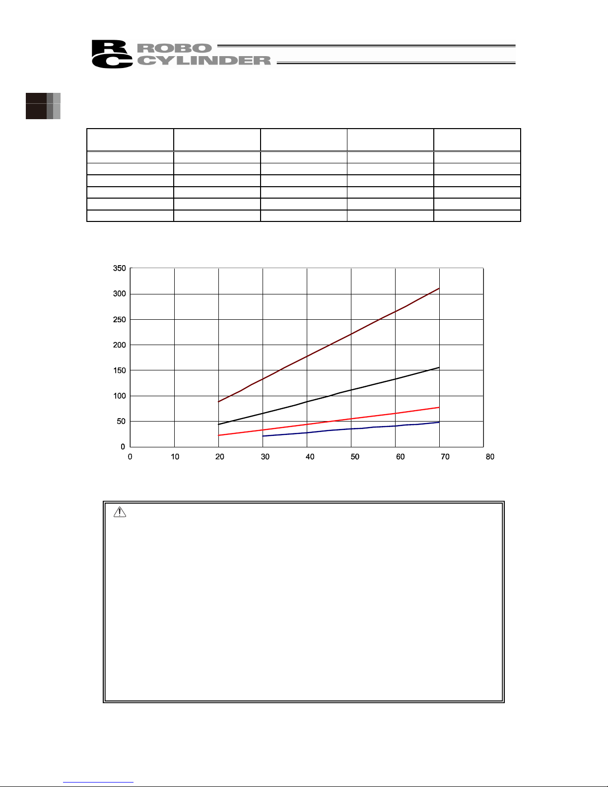
1.2.6 Current Limit Value and Pressing Force
[1] RA4C and RA4R Motor Type 35P
Current Limit
Value
Lead2.5 [N] Lead 5 [N] Lead 10 [N] Lead 16 [N]
20% 88 44 22 30% 133 66 33 21
40% 177 88 44 28
50% 221 111 55 35
60% 265 133 66 41
70% 310 155 77 48
Caution: (1) The relation of the current limit and the pressing force is a reference when
assuming the speed is 20mm/s.
(2) There is a little variance in the actual pressing force. The variance of the
pressing force becomes large when the current limit value is low.
(3) Use the product within the range in the graph for the current limit value.
Pressing force will not be stable if used below 20% (below 30% for Lead
16). There is even a case that it would not operate. An operation cannot be
made also when it is beyond 70%. Doing so may cause degradation in the
motor coil insulation by heat radiation, which results in shortening the
product life.
(4) For CON-system controllers such as PCON, when the approach speed to
the pressing start position (setting in the position table) is 20mm/s or less,
pressing will be performed with the approach speed In such a case also
the pressing force will be unstable. In such cases, check in advance that
the actuator can be used with no problem before omit using.
For SEL-system controllers, such as MSEL, press at the speed set by
PAPR instruction, regardless of the approach speed up to the pressing
start position.
Current Limit Value [%]
Lead 2.5
Lead 5
Lead 10
Lead 16
Pressing Force [N]
RA4C/R Current Limit Value and Pressing Force

49
1. Specifications Check
[2] RA6C and RA6R Motor Type 42P
Current Limit
Value
Lead 3 [N] Lead 6 [N] Lead 12 [N] Lead 20 [N]
20% 106 53 26 16
30% 159 79 40 24
40% 211 106 53 32
50% 264 132 66 40
60% 317 159 79 48
70% 370 185 93 56
Caution: (1) The relation of the current limit and the pressing force is a reference when
assuming the speed is 20mm/s.
(2) There is a little variance in the actual pressing force. The variance of the
pressing force becomes large when the current limit value is low.
(3) Use the product within the range in the graph for the current limit value.
Pressing force will not be stable if used below 20%. There is even a case
that it would not operate. An operation cannot be made also when it is
beyond 70%. Doing so may cause degradation in the motor coil insulation
by heat radiation, which results in shortening the product life.
(4) For CON-system controllers such as PCON, when the approach speed to
the pressing start position (setting in the position table) is 20mm/s or less,
pressing will be performed with the approach speed In such a case also
the pressing force will be unstable. In such cases, check in advance that
the actuator can be used with no problem before omit using.
For SEL-system controllers, such as MSEL, press at the speed set by
PAPR instruction, regardless of the approach speed up to the pressing
start position.
Current Limit Value [%]
Lead 12
Lead 20
Lead 6
Lead 3
Pressing Force [N]
RA6C/R Current Limit Value and Pressing Force

50
1. Specifications Check
[3] RA7C and RA7R Motor Type 56P
Current Limit
Value
Lead 4 [N] Lead 8 [N] Lead 16 [N] Lead 24 [N]
20% 312 156 78 52
30% 469 234 117 78
40% 625 312 156 104
50% 781 391 195 130
60% 937 469 234 156
70% 1094 547 273 182
Caution: (1) The relation of the current limit and the pressing force is a reference when
assuming the speed is 20mm/s.
(2) There is a little variance in the actual pressing force. The variance of the
pressing force becomes large when the current limit value is low.
(3) Use the product within the range in the graph for the current limit value.
Pressing force will not be stable if used below 20%. There is even a case
that it would not operate. An operation cannot be made also when it is
beyond 70%. Doing so may cause degradation in the motor coil insulation
by heat radiation, which results in shortening the product life.
(4) For CON-system controllers such as PCON, when the approach speed to
the pressing start position (setting in the position table) is 20mm/s or less,
pressing will be performed with the approach speed In such a case also
the pressing force will be unstable. In such cases, check in advance that
the actuator can be used with no problem before omit using.
For SEL-system controllers, such as MSEL, press at the speed set by
PAPR instruction, regardless of the approach speed up to the pressing
start position.
Current Limit Value [%]
Lead 16
Lead 24
Lead 8
Lead 4
Pressing Force [N]
RA7C/R Current Limit Value and Pressing Force

51
1. Specifications Check
[4] RA8C and RA8R Motor Type 60P
Current Limit Value Lead 5 [N] Lead 10 [N] Lead 20 [N]
20% 667 333 167
30% 1000 500 250
40% 1333 667 333
50% 1667 833 417
60% 2000 1000 500
Caution: (1) The relation of the current limit and the pressing force is a reference when
assuming the speed is 10mm/s.
(2) There is a little variance in the actual pressing force. The variance of the
pressing force becomes large when the current limit value is low.
(3) Use the product within the range in the graph for the current limit value.
Pressing force will not be stable if used below 20%. There is even a case
that it would not operate. An operation cannot be made also when it is
beyond 60%. Doing so may cause degradation in the motor coil insulation
by heat radiation, which results in shortening the product life.
(4) For CON-system controllers such as PCON, when the approach speed to
the pressing start position (setting in the position table) is 10mm/s or less,
pressing will be performed with the approach speed In such a case also
the pressing force will be unstable. In such cases, check in advance that
the actuator can be used with no problem before omit using.
For SEL-system controllers, such as MSEL, press at the speed set by
PAPR instruction, regardless of the approach speed up to the pressing
start position.
Current Limit Value [%]
Lead 20
Lead 10
Lead 5
Pressing Force [N]
RA8C/R Current Limit Value and Pressing Force

52
1. Specifications Check
1.2.7 Rod Tip Inclination Amount (reference)
This is a calculated value from the clearances of bearing gaps and whirl-stops.
RA4C, RA4R Rod Tip Inclination Amount (Reference)
RA6C, RA6R Rod Tip Inclination Amount (Reference)
Nominal st 50
Nominal st 100
Nominal st 150
Nominal st 200
Stroke
(
Coordinate Position) [mm]
Stroke (Coordinate Position) [mm]
Nominal st 200
Nominal st 150
Nominal st 100
Nominal st 50
Nominal st 250
Nominal st 300
Inclination Amount (Amplitude)
Reference [mm]
Inclination Amount (Amplitude)
Reference [mm]

53
1. Specifications Check
RA7C, RA7R Rod Flexure (Reference)
RA8C, RA8R Rod Flexure (Reference)
Nominal st 200
Nominal st 150
Nominal st 100
Nominal st 50
Nominal st 250
Nominal st 300
Nominal st 200
Nominal st 150
Nominal st 100
Nominal st 50
Nominal st 250
Nominal st 300
Stroke (Coordinate Position) [mm]
Stroke
(
Coordinate Position) [mm]
Inclination Amount (Amplitude)
Reference [mm]
Inclination Amount (Amplitude)
Reference [mm]

54
1. Specifications Check
1.2.8 Duty Ratio for Continuous Operation
[Standard Specification]
It can operate continuously when the duty ratio is 100%.
[Standard Specification]
It can operate continuously when the duty ratio is 100%.
[Built-in Controller Specification]
◎ RCP6S-RA4C, 4R
It can operate continuously when the duty ratio is 100%.
◎ RCP6S-RA6C, 6R
Lead 12mm and 20mm can operate continuously when the duty ratio is 100%.
Operate with the duty ratio as in the following graph for lead 3mm and 6mm.
◎ RCP6S-RA7C, 7R
Lead 24mm can operate continuously when the duty ratio is 100%.
Operate with the duty ratio as in the following graph for lead 4mm, 8mm, and 16mm.
◎ RCP6S-RA8C, 8R
Operate with the duty ratio of 70% or less.
Duty ratio is an operating rate, which indicates the time that the actuator is running in one cycle by
percentage.
Duty ratio(%)
Temperature(°C)
Lead 3mm
Lead 6mm
38°C
Duty ratio(%)
Temperaturere(°C)
Lead 4mm
Lead 8mm
37°C
35°C
Lead 16mm

55
1. Specifications Check
1.3 Options
1.3.1 Brake Type (Model: B)
The brake is a mechanism designed to prevent the rod from dropping on a vertically installed
actuator when the power or servo is turned OFF.
Use the brake to prevent the installed load, etc., from being damaged due to the falling rod.
1.3.2 Reversed-home Specification (Model: NM)
The standard home position is on the motor side. However, the motor position will be reversed if it
is desirable in view of the layout of the system, etc.
(Note) The home position is adjusted at the factory before shipment. If you wish to change the
home after the delivery of your actuator, you must return the actuator to IAI for adjustment.
1.3.3 Flange Bracket (Front) (Model: FL)
This is the flange bracket to attach on the front of the main unit.
Figure 2-2-2
Model RA4 RA6 RA7 RA8
Model code of
single product
RCP6-FL-RA4 RCP6-FL-RA6 RCP6-FL-RA7 RCP6-FL-RA8
Wf[mm] 70 90 108 135
Hf[mm] 40 56 68 84
Ph[mm] 60 75 90 115
Pv[mm] 25 40 50 65
h[mm] 4.5 6.6 8.5 8.5
Tf[mm] 10 12 16 19

56
1. Specifications Check
1.3.4 Foot Bracket (Model: FT)
This is a bracket for fixing the actuator body from the top with the bolts.
[For the dimensions, refer to 2.3.2 “Installation of the Main Unit [2] Installation by Using Foot
Brackets”]
1.3.5 T-slot Nut Bar (Model: NTB)
These are bar-shaped brackets that plug into the actuator’s T-slots.
There is a nut hole in the predetermined position on the T-slot nut bar.
[For the dimensions, refer to 2.3.2 “Installation of the Main Unit [1] Using the T-slot on the Bottom
of the Base”]
T-Slot Nut Bar

57
1. Specifications Check
1.3.6 Tip Adapter (Internal Thread) (Model: NFA)
Applicable Units : RA4C, RA4R, RA6C, RA6R, RA7C, RA7R, RA8C, RA8R
This is an adapter to attach on the rod end an object such as a fixture with one screw.
◎ RA4C and RA4R
[Model code of single product : RCP6-NFA-RA4]
◎ RA6C and RA6R
[Model code of single product : RCP6-NFA-RA6]
M10 × 1.5 Depth 15
41
35
The angle of the width
across flat is undefined.
62.5(Home Position)
62.5(Home Position)
41
35
M10 × 1.5 Depth 15
The angle of the width
across flat is undefined.
ø20
32
ø20
26

58
1. Specifications Check
◎ RA7C and RA7R
[Model code of single product : RCP6-NFA-RA7]
◎ RA8C and RA8R
[Model code of single product : RCP6-NFA-RA8]
M12 × 1.75 Depth 20
The angle of the width
across flat is undefined.
84.5(Home Position)
38
ø26
58
50
M20 × 2.5 Depth 30
The angle of the width across
flat is undefined.
50
ø35
127.5(Home Position)
82
70

59
1. Specifications Check
1.3.7 Motor Left Side-Mounted, Motor Top Side-Mounted, Motor Right
Side-Mounted (Model: ML, MT, MR)
From the view of the motor side, the type with the motor side-mounted to the left is ML, the motor
side-mounted to the top is MT, and the motor side-mounted to the right is MR.
1.3.8 Cable Exit Direction Changed (Model: CJT, CJR, CJL, CJB, CJO)
If a change in the cable exit direction is made, the direction of cable exit will be changed.
There are ejection directions, top (model: CJT), right (model: CJR), left (model: CJL), bottom
(model: CJB) and outward (model: CJO). The side-mounted motor type of RA4R, RA6R, RA7R,
and RA8R can only be selected for CJO.
Figure viewed from
motor side
Figure viewed from
rod side
ML
(Left
Side-Mounted)
MT
(Top
Side-Mounted)
MR
(Right
Side-Mounted)
Outward
(Model: CJO)
Bottom
(Model: CJB)
Right Side
(Model: CJR)
Left Side
(Model: CJL)
Top
(Model: CJT)

60
1. Specifications Check
1.4 Motor • Encoder Cables
1.4.1 Motor • Encoder Integrated Cables (RA4, RA6 and RA7)
CB-CAN-MPA□□□ □□□ indicates the cable length (L) (Example: 030=3m), Max.20m
Connection diagram
Actuator side Controller side
Thickness
Electric
Wire Color
Symbol Pin No. Pin No. Symbol
Electric
Wire Color
Thickness
AWG22/19 Blue ɸA 3 1 ɸA Blue AWG22/19
AWG22/19 Orange VMM 5 2 VMM Orange AWG22/19
AWG22/19 Brown ɸB 10 3 ɸB Brown AWG22/19
AWG22/19 Gray VMM 9 4 VMM Gray AWG22/19
AWG22/19 Green ɸ_A 4 5 ɸ_A Green AWG22/19
AWG22/19 Red ɸ_B 15 6 ɸ_B Red AWG22/19
AWG26 Black LS+ 8 7 LS+ Black AWG26
AWG26 Yellow LS- 14 8 LS- Yellow AWG26
AWG26 Blue SA 12 11 SA Blue AWG26
AWG26 Orange SB 17 12 SB Orange AWG26
AWG26 Green A+ 1 13 A+ Green AWG26
AWG26 Brown A- 6 14 A- Brown AWG26
AWG26 Gray B+ 11 15 B+ Gray AWG26
AWG26 Red B- 16 16 B- Red AWG26
AWG26 Blue BK+ 20 9 BK+ Blue AWG26
AWG26 Orange BK- 2 10 BK- Orange AWG26
AWG26 Gray VCC 21 17 VCC Gray AWG26
AWG26 Red GND 7 19 GND Red AWG26
AWG26 Brown VPS 18 18 VPS Brown AWG26
AWG26 Green LS_GND 13 20 LS_GND Green AWG26
- - - 19 22 - -
AWG26 Pink - 22 21 - Pink AWG26
- - - 23 23 - -
AWG26 Black FG 24 24 FG Black AWG26
(Note) About thickness AWG22/19
The thickness is AWG22 when the cable length is 5m or less, and AWG19 when longer than
5m.
Controller side
Connector: PADP-24V-1-S
Contact:
SPND-002T-C0.5 (For AWG26)
SPND-001T-C0.5 (For AWG22)
Actuator side
Connector: DF62B-24S-2.2C
Contact: DF62-2428SCFA (For AWG26)
DF62-22SCFA (For AWG22)

61
1. Specifications Check
1.4.2 Motor • Encoder Integrated Cables Robot Type (RA4, RA6 and RA7)
CB-CAN-MPA□□□-RB □□□ indicates the cable length (L) (Example: 030=3m), Max.20m
Connection diagram
Actuator side Controller side
Thickness
Electric
Wire Color
Symbol Pin No. Pin No. Symbol
Electric
Wire Color
Thickness
AWG22/19 Blue ɸA 3 1 ɸA Blue AWG22/19
AWG22/19 Orange VMM 5 2 VMM Orange AWG22/19
AWG22/19 Brown ɸB 10 3 ɸB Brown AWG22/19
AWG22/19 Gray VMM 9 4 VMM Gray AWG22/19
AWG22/19 Green ɸ_A 4 5 ɸ_A Green AWG22/19
AWG22/19 Red ɸ_B 15 6 ɸ_B Red AWG22/19
AWG26 Black LS+ 8 7 LS+ Black AWG26
AWG26 Yellow LS- 14 8 LS- Yellow AWG26
AWG26 Blue SA 12 11 SA Blue AWG26
AWG26 Orange SB 17 12 SB Orange AWG26
AWG26 Green A+ 1 13 A+ Green AWG26
AWG26 Brown A- 6 14 A- Brown AWG26
AWG26 Gray B+ 11 15 B+ Gray AWG26
AWG26 Red B- 16 16 B- Red AWG26
AWG26 Blue BK+ 20 9 BK+ Blue AWG26
AWG26 Orange BK- 2 10 BK- Orange AWG26
AWG26 Gray VCC 21 17 VCC Gray AWG26
AWG26 Red GND 7 19 GND Red AWG26
AWG26 Brown VPS 18 18 VPS Brown AWG26
AWG26 Green LS_GND 13 20 LS_GND Green AWG26
- - - 19 22 - -
AWG26 Pink - 22 21 - Pink AWG26
- - - 23 23 - -
AWG26 Black FG 24 24 FG Black AWG26
(Note) About thickness AWG22/19
The thickness is AWG22 when the cable length is 5m or less, and AWG19 when longer than
5m.
Actuator side
Connector: DF62B-24S-2.2C
Contact: DF62-2428SCFA (For AWG26)
DF62-22SCFA (For AWG22)
Controller side
Connector: PADP-24V-1-S
Contact:
SPND-002T-C0.5 (For AWG26)
SPND-001T-C0.5 (For AWG22)

62
1. Specifications Check
1.4.3 Motor • Encoder Integrated Cables (RA8)
CB-CFA3-MPA□□□ □□□ indicates the cable length (L) (Example: 030=3m), Max.20m
Connection diagram
Actuator side Controller side
Thickness
Electric
Wire Color
Symbol Pin No. Pin No. Symbol
Electric
Wire Color
Thickness
AWG22/19 Blue ɸA A1 1 ɸA Blue AWG22/19
AWG22/19 Orange VMM B1 2 VMM Orange AWG22/19
AWG22/19 Green ɸ_A A2 5 ɸ_A Green AWG22/19
AWG22/19 Brown ɸB B2 3 ɸB Brown AWG22/19
AWG22/19 Gray VMM A3 4 VMM Gray AWG22/19
AWG22/19 Red ɸ_B B3 6 ɸ_B Red AWG22/19
AWG26 Black LS+ A4 7 LS+ Black AWG26
AWG26 Yellow LS- B4 8 LS- Yellow AWG26
AWG26 Blue SA A6 11 SA Blue AWG26
AWG26 Orange SB B6 12 SB Orange AWG26
AWG26 Green A+ A7 13 A+ Green AWG26
AWG26 Brown A- B7 14 A- Brown AWG26
AWG26 Gray B+ A8 15 B+ Gray AWG26
AWG26 Red B- B8 16 B- Red AWG26
AWG26 Blue BK+ A5 9 BK+ Blue AWG26
AWG26 Orange BK- B5 10 BK- Orange AWG26
AWG26 Green LS_GND A9 20 LS_GND Green AWG26
AWG26 Brown VPS B9 18 VPS Brown AWG26
AWG26 Gray VCC A10 21 VCC Gray AWG26
AWG26 Red GND B10 19 GND Red AWG26
- - A11 17 - - -
AWG26 Black FG B11 22 - AWG26
23 - - -
24 FG Black AWG26
(Note) About thickness AWG22/19
The thickness is AWG22 when the cable length is 5m or less, and AWG19 when longer than
5m.
Actuator side
Connector: 1-1827863-1
Contact: 1827570-2
Controller side
Connector: PADP-24V-1-S
Contact:
SPND-002T-C0.5 (For AWG26)
SPND-001T-C0.5 (For AWG22)

63
1. Specifications Check
1.4.4 Motor • Encoder Integrated Cables (RA8)
CB-CFA3-MPA□□□-RB indicates the cable length (L) (Example: 030=3m), Max.20m
Connection diagram
Actuator side Controller side
Thickness Electric
Wire Color
Symbol Pin No. Pin No. Symbol Electric
Wire Color
Thickness
AWG22/19 Blue ɸA A1 1 ɸA Blue AWG22/19
AWG22/19 Orange VMM B1 2 VMM Orange AWG22/19
AWG22/19 Green ɸ_A A2 5 ɸ_A Green AWG22/19
AWG22/19 Brown ɸB B2 3 ɸB Brown AWG22/19
AWG22/19 Gray VMM A3 4 VMM Gray AWG22/19
AWG22/19 Red ɸ_B B3 6 ɸ_B Red AWG22/19
AWG26 Black LS+ A4 7 LS+ Black AWG26
AWG26 Yellow LS- B4 8 LS- Yellow AWG26
AWG26 Blue SA A6 11 SA Blue AWG26
AWG26 Orange SB B6 12 SB Orange AWG26
AWG26 Green A+ A7 13 A+ Green AWG26
AWG26 Brown A- B7 14 A- Brown AWG26
AWG26 Gray B+ A8 15 B+ Gray AWG26
AWG26 Red B- B8 16 B- Red AWG26
AWG26 Blue BK+ A5 9 BK+ Blue AWG26
AWG26 Orange BK- B5 10 BK- Orange AWG26
AWG26 Green LS_GND A9 20 LS_GND Green AWG26
AWG26 Brown VPS B9 18 VPS Brown AWG26
AWG26 Gray VCC A10 21 VCC Gray AWG26
AWG26 Red GND B10 19 GND Red AWG26
- - A11 17 - - -
AWG26 Black FG B11 22 - AWG26
23 - - -
24 FG Black AWG26
(Note) About thickness AWG22/19
The thickness is AWG22 when the cable length is 5m or less, and AWG19 when longer than
5m.
Actuator side
Connector: 1-1827863-1
Contact: 1827570-2
Controller side
Connector: PADP-24V-1-S
Contact:
SPND-002T-C0.5 (For AWG26)
SPND-001T-C0.5 (For AWG22)

64
2. Installation
2. Installation
2.1 Transportation
[1] Handling of Robot
(1) Handling the Packed Unit
Unless otherwise specified, the actuator is shipped with each axis packaged separately.
• Do not damage or drop. No special treatment is conducted on this package to endure a drop or
impact on it.
• Do not attempt to carry a heavy package with only one worker. Consider an appropriate method
for transportation.
• Keep the unit in horizontal orientation when placing it on the ground or transporting. Follow the
instruction if there is any for the packaging condition.
• Do not step or sit on the package.
• Do not put any load that may cause a deformation or breakage of the package.
(2) Handling the Actuator After Unpacking
• Do not carry an actuator by motor unit and a cable or attempt to move it by pulling the cable.
• Be careful not to bump the actuator into anything when moving it.
• Hold the body base when transporting the actuator.
• Do not apply an excessive force to each part of the actuator.
Supplement) For the names of each part of the actuator, refer to “Names of the Parts”

65
2. Installation
[2] Handling in the Assembled Condition
This is the case when the product is delivered from our factory under a condition that it is
assembled with other actuators. The combined axes are delivered in a package that the frame is
nailed on the lumber base. Fix the rod so that would not accidentally move during transportation.
The actuators are also fixed so the tip of it would not shake due to the external vibration.
(1) Handling the Packed Unit
• Do not hit or drop the package. No special treatment is conducted on this package to endure a
drop or impact on it.
• Do not attempt to carry a heavy package with only one worker. Also, have an appropriate
method for transportation.
• When hanging up with ropes, support on the reinforcement frame on the bottom of the lumber
base. When bringing up the package with a forklift, also support on the bottom of the lumber
base.
• Handle with care when putting the package down to avoid impact or bounce.
• Do not step on the package.
• Do not put any load that may cause a deformation or breakage of the package.
(2) How to Handle after Unpackaged
• Secure the rods to prevent sudden movement during transport.
• If the tip of an actuator is overhanging, have an appropriate way to fix it to avoid shake due to the
external vibration. In the transportation without the tip being fixed, do not apply any impact with
0.3G or more.
• When hanging up with ropes, have appropriate cushioning to avoid any deformation of the
actuator body. Also keep it in stable horizontal orientation. Make a fixture utilizing the attachment
holes and the tapped holes on the actuator body if necessary.
• Do not attempt to apply load on the actuators or the connector box. Also pay attention not to
pinch cables and bend or deform them forcefully.
[3] Handling in Condition of being assembled in Machinery Equipment (System)
These are some caution notes for when transporting the actuator being assembled in the
machinery equipment (system):
• Secure the rods to prevent sudden movement during transport.
• If the tip of an actuator is overhanging, have an appropriate way to fix it to avoid shake due to the
external vibration. In the transportation without the tip being fixed, do not apply any impact with
0.3G or more.
• When hanging up the machinery equipment (system) with ropes, do not attempt to apply load on
the actuators or the connector box. Also pay attention not to pinch cables and bend or deform
them forcefully.

66
2. Installation
2.2 Installation and Storage • Preservation Environment
[1] Installation Environment
The actuator should be installed in a location other than those specified below.
In general, the installation environment should be one in which an operator can work without
protective gear.
Also provide sufficient work space required for maintenance inspection.
• Where the actuator receives radiant heat from strong heat sources such as heat treatment
furnaces
• Where the ambient temperature exceeds the range of 0 to 40°C
• Where the temperature changes rapidly and condensation occurs
• Where the relative humidity exceeds 85% RH
• Where the actuator receives direct sunlight
• Where the actuator is exposed to corrosive or combustible gases
• Where the ambient air contains a large amount of powder dust, salt or iron (at level exceeding
what is normally expected in an assembly plant)
• Where the actuator is subject to splashed water, oil (including oil mist or cutting fluid) or chemical
solutions
• Where the actuator receives impact or vibration
• Where the altitude is more than 2000m
If the actuator is used in any of the following locations, provide sufficient shielding measures:
• Where noise generates due to static electricity, etc.
• Where the actuator is subject to a strong electric or magnetic field
• Where the actuator is subject to ultraviolet ray or radiation
[2] Storage • Preservation Environment
• The storage and preservation environment should comply with the same standards as those for
the installation environment. In particular, when the machine is to be stored for a long time, pay
close attention to environmental conditions so that no dew condensation forms.
• Unless specially specified, moisture absorbency protection is not included in the package when
the machine is delivered. In the case that the machine is to be stored and preserved in an
environment where dew condensation is anticipated, take the condensation preventive
measures from outside of the entire package, or directly after opening the package.
• For storage and preservation temperature, the machine withstands temperatures up to 60°C for
a short time, but in the case of the storage and preservation period of 1 month or more, control
the temperature to 50°C or less.
• Storage and preservation should be performed in the horizontal condition. In the case it is stored
in the packaged condition, follow the posture instruction if any displayed on the package.

67
2. Installation
2.3 How to Install
This chapter explains how to install the actuator on your mechanical system.
2.3.1 Installation
Follow the information below when installing the actuator, as a rule.
Do pay attention to these items (except with custom-order models).
○ : Possible △ : Daily inspection is required × : Not possible
Model
Horizontal
installation
Vertical
installation
Sideway
installation
Ceiling mount
installation
RA4C, RA4R
RA6C, RA6R
RA7C, RA7R
RA8C, RA8R
○ ○ ○ ○
Installation Orientation
Horizontal Vertical Sideways Ceiling mount
Note: · Grease has been applied to the outer periphery of the rod. Protect the peripheral
equipments if they are affected by grease adhesion.
· When the unit is installed vertically oriented, Motor straight type is attempt to put
the motor up unless there is a special reason. · Putting the motor on the lower side
would not cause a problem in an ordinary operation. However, it may rarely cause
a problem, when it is not operated for a long period, depending on the surrounding
environment (especially high temperature), caused by the grease being separated
and the base oil flowing into the motor unit.

68
2. Installation
2.3.2 Installation of the Main Unit
The surface to mount the main unit should be a machined surface or a plane that possesses an
equivalent accuracy and the flatness should be within 0.05mm/m. Also, the platform should have a
structure stiff enough to install the unit so it would not generate vibration or other abnormality.
Also consider enough space necessary for maintenance work such as actuator replacement and
inspection.
T-slots are provided on the back of the actuator.
Nut holes are provided on the actuator frame front and the side-mounted motor type rear bracket.
Using these parts, the following installations can be realized.
· Installation by using T-slots
· Installation by using foot brackets (option: model FT)
· Installing main unit frame front
· Installation by using flange (option: model FL)
· Installation by using rear bracket for side-mounted motor types
[1] Using the T-slot on the Bottom of the Base
This actuator has T-slot for mounting so it can be fixed from the bottom of the base.
There are two methods of installation: using square T-nuts into T-slots or using optional T-slot nut
bars (model: NTB).
(1) T-slots Dimensions
RA4 RA6 RA7 RA8
W[mm] 40 58 70 85
Pt[mm] 17 25 35 40
A[mm] 4.3 6.3 6.3 8.5
B[mm] 7.3 10.3 10.3 13.3
C[mm] 7.7 9 10.5 14

69
2. Installation
(2) Installation by Square Nuts
Square nuts prescribed in JISB1163 can be used for the T-slots.
Quantities of the square nuts enclosed at the time of shipment are as follows.
(Note) When optional T-slot nut bars (model: NTB) are selected, the square nuts are not enclosed.
Adjust the screw length from the base bottom according to the following table to ensure the fitting
length of the nut and the screw.
Install them according to the minimum fixing number of bolts and the tightening torque in the
following table.
RA4 RA6 RA7 RA8
Quantities
Enclosed
4 4 8 8
Attachment
Bolts
M4 M6 M6 M8
RA4 RA6 RA7 RA8
Screw Length
[mm]
From the Base
Bottom
5 to 7 7.5 to 8.5 8 to 10 11 to 13
RA4 RA6 RA7 RA8
Minimum Fixing
Number (Bolts)
4 4 6 8
Tightening
Torque[Nm]
1.76 5.36 5.36 11.48
Caution: Be careful when selecting the bolt length. If bolts of inappropriate lengths are
used, the tapped holes may be damaged, actuator mounting strength may
become insufficient, or contact with driving parts may occur, resulting in lower
precision or unexpected accidents.

70
2. Installation
(3) Installation by T-Slot Nut Bar (Option Model: NTB)
Figure 2-1-4
Four T-slot nut bars (option model: NTB) are shipped in a built-in-state in all sizes.
Before you use them, loosen the hexagonal socket head fixing screws in the center of the nuts to
move them to the desired positions. Do not overly tighten the hexagonal socket head fixing screws,
for they are used only for positioning. Use the nut bars in a pitch as wide as possible to stabilize the
mounting.
Adjust the screw length from the base bottom according to the following table to ensure the fitting
length of the nut and the screw.
Install them according to the minimum fixing number of bolts and the tightening torque in the
following table.
RA4 RA6 RA7 RA8
Screw Length
[mm]
From the Base
Bottom
5 to 7 7.5 to 8.5 8 to 10 11 to 13
RA4 RA6 RA7 RA8
Minimum Fixing
Number (Bolts)
4 4 6 8
Tightening
Torque[Nm]
1.76 5.36 5.36 11.48
Caution: Be careful when selecting the bolt length. If bolts of inappropriate lengths are
used, the tapped holes may be damaged, actuator mounting strength may
become insufficient, or contact with driving parts may occur, resulting in lower
precision or unexpected accidents.

71
2. Installation
The attachable positions of T-Slot nut bars (model: NTB) are as follows.
RA4
RA6
RA7
Maximum: Stroke -12
Minimum: 10
Stroke +9 8
Stroke +122.5
Maximum: Stroke +12.5
Minimum: 10
Maximum: Stroke +37.5
Minimum: 10
Stroke +147.5
(
)
(
)
(
)

72
2. Installation
RA8
Stroke +185.5
Maximum: Stroke +70.5
Minimum: 15
(
)

73
2. Installation
[2] When Utilizing Foot Brackets for Installation
Actuators can be installed by using the foot brackets (option: model FT).
Foot bases are shipped in the state fixed to the both ends of the actuator frame.
Before use, loosen the bolts fixing the foot bases and move them to the desired positions.
[Width direction pitch of foot bracket, attachment bolts and others]
Straight Type, Motor Top Side-Mounted Type (Model: MT)
Motor Left Side-Mounted (Model: ML), Motor Right Side-Mounted (Model: MR) Except
RCP6S-RA4R
Motor Left Side-Mounted (Model: ML), Motor Right Side-Mounted (Model: MR) of RCP6S-RA4R
[Tightening Torque]
RA4 RA6 RA7 RA8
Width Direction
Hole Pitch [mm]
50 72 85 100
Thickness [mm] 8 10 12 16
Material Steel Steel Steel Steel
Attachment Bolts M4 M6 M6 M8
RA4 RA6 RA7 RA8
Width Direction
Hole Pitch [mm]
100 132 160 190
Thickness [mm] 8 10 12 16
Material Steel Steel Steel Steel
Attachment Bolts M4 M6 M6 M8
RA4 RA6 RA7 RA8
Width Direction
Hole Pitch [mm]
121
Thickness [mm] 8
Material Steel
Attachment Bolts M4
Model Screw
Nominal
Diameter
In the case that steel is used
for the bolt seating surface:
RA4 M4
3.59N・m(0.37kgf・m)
RA6, RA7 M6
12.3N・m(1.26kgf・m)
RA8 M8
30N・m(3.1kgf・m)

74
2. Installation
The attachment positions of foot brackets (model: FT) at the shipment are as follows.
RCP6(S)-RA4C
RCP6(S)-RA4R Motor Top Side-Mounted Type (Model: MT)
RCP6-RA4R Motor Left Side-Mounted (ML), Motor Right Side-Mounted (MR)
RCP6S-RA4R Motor Left Side-Mounted (ML), Motor Right Side-Mounted (MR)
Stroke +86
Stro ke +86
Stroke +86

75
2. Installation
RCP6(S)-RA6C
RCP6(S)-RA6R Motor Top Side-Mounted Type (Model: MT)
RCP6(S)-RA6R Motor Left Side-Mounted (ML), Motor Right Side-Mounted (MR)
Stroke +102.5
Stroke +102.5
Stroke +102.5

76
2. Installation
RCP6(S)-RA7C
RCP6(S)-RA7R-MT Motor Top Side-Mounted Type (Model: MT)
RCP6(S)-RA7R Motor Left Side-Mounted (ML), Motor Right Side-Mounted (MR)
Stroke +32.5
Stroke +32.5
Stroke +32.5

77
2. Installation
RCP6(S)-RA8C
RCP6(S)-RA8R Motor Top Side-Mounted Type (Model: MT)
RCP6(S)-RA8R Motor Left Side-Mounted (ML), Motor Right Side-Mounted (MR)
Stroke +60.5
Stroke +60.5
Stroke +60.5

78
2. Installation
Tightening Screws
• Use hexagonal socket head bolts for the male threads for installing the base.
• Use of high-tension bolts meeting at least ISO 10.9 is recommended.
• For the effective engagement length between the bolt and female thread, provide at least the
applicable value specified below:
Female thread is made of steel material → Same length as the nominal diameter
Female thread is made of aluminum → 1.8 times of nominal diameter
Caution: Be careful when selecting the bolt length. If bolts of inappropriate lengths are
used, actuator mounting strength may become insufficient, or contact with driving
parts may occur, resulting in lower precision or unexpected accidents.

79
2. Installation
[3] When using Tapped Holes on Front Bracket
There are tapped holes equipped on the front bracket.
Utilize these tapped holes for installation.
The effective depth for the attachment screws is as shown below;
Figure 2-2-1
[Tightening Torque]
Make sure to follow “◎ Caution for Installation using Front Bracket and Front Flange”
Tightening screws
• Use hexagonal socket head bolts for the male threads for installing the base.
• Use of high-tension bolts meeting at least ISO 10.9 is recommended.
• Have the length of thread engagement approximately 1.8 times of the nominal diameter.
RA4 RA6 RA7 RA8
W[mm] 40 58 70 85
h[mm] 26 32 38 50
H[mm] 46 61 73 92.5
Pm[mm] 32 45 55 70
N M4 Depth 8 M6 Depth 12 M8 Depth 16 M8 Depth 16
D[mm] ø20 ø25 ø30 ø40
E[mm] ø38h7 ø46h7 ø52h7 ø64h7
F[mm] 2 2 2 2
Model Screw
Nominal
Diameter
In the case that steel is used
for the bolt seating surface:
In the case that aluminum is
used for the bolt seating
surface:
RA4 M4
3.59N・m(0.37kgf・m) 1.76N・m(0.18kgf・m)
RA6, RA7 M6
12.3N・m(1.26kgf・m) 5.4N・m(0.55kgf・m)
RA8 M8
30N・m(3.1kgf・m) 11.5N・m(1.2kgf・m)
Caution: Be careful when selecting the bolt length. If bolts of inappropriate lengths are
used, the tapped holes may be damaged, actuator mounting strength may
become insufficient, or contact with driving parts may occur, resulting in lower
precision or unexpected accidents.

80
2. Installation
◎ Caution for Installation using Front Bracket
Do not attempt to apply any external force to the body when installing with front bracket. External
force may cause an operation failure or parts malfunction.
Prepare a support block as shown in the figure below for the horizontal installation of the unit with
its stroke more than 150 even if there is no external force applied on the body. Even for those with
the stroke less than 150, it is recommended to have a support block to avoid vibration being
generated due to the operation condition or installation environment, which may cause an
operation failure or parts malfunction.
Support
Block
×
External Force
×
External Force

81
2. Installation
[4] When using Front Flange (Option)
There are tapped holes equipped on the front housing (Option).
Utilize these tapped holes for installation.
[Refer to 9. “External Dimensions” for the dimensions after attaching the front flange.]
Although this option is ordered along with an actuator, they will be shipped as accessories (not
assembled parts). Attach the flange to the actuator using the enclosed bolts with prescribed
torque.
(Note) The front flange cannot be installed in the vertical direction (height direction) because the
Motor Top Side-Mounted Types (Model: MT) of side-mounted motor types RA4R, RA6R,
RA7R, and RA8R with the following strokes will interfere with the motor unit.
(Note) The front flange cannot be installed in the horizontal direction (width direction) because
Motor Left Side-Mounted (ML) and Motor Right Side-Mounted (MR) of side-mounted motor
types RA4R, RA6R, RA7R, and RA8R with the following strokes will interfere with the motor
unit.
Model Name Stroke
RCP6-RA4R
50、100、150
RCP6S-RA4R
50、100、150
RCP6-RA6R
50、100
RCP6S-RA6R
50、100、150、200
RCP6-RA7R
50、100、150
RCP6S-RA7R
50、100、150、200
RCP6-RA8R
50、100
RCP6S-RA8R
50、100、150
(Note) Be cautious that the end cover may be projected from the entire actuator frame in the case
of reserving types.

82
2. Installation
Flatness of the mounting surface should be less than 0.050mm.
The dimensions of the front flange are as follows.
[Tightening Torque]
Make sure to follow “◎ Caution for Installation using Front Bracket and Front Flange”
Tightening screws
• Use hexagonal socket head bolts for the male threads for installing the base.
• Use of high-tension bolts meeting at least ISO 10.9 is recommended.
• For the effective engagement length between the bolt and female thread, provide at
least the applicable value specified below:
Female thread is made of steel material → Same length as the nominal diameter
Female thread is made of aluminum → 1.8 times of nominal diameter
RA4 RA6 RA7 RA8
Wf[mm] 70 90 108 135
Hf[mm] 40 56 68 84
Ph[mm] 60 75 90 115
Pv[mm] 25 40 50 65
h[mm] 4.5 6.6 8.5 8.5
Tf[mm] 10 12 16 19
Material Steel Steel Steel Steel
Enclosed Bolts M4x12 M6x15 M8x20 M8x25
Tightening Torque
of the Front
Flange to the
Main Unit [N
•m]
2.1 4.2 7.1 17.2
Model
Screw
Nominal
Diameter
In the case that steel is used
for the bolt seating surface:
RA4 M4
3.59N・m(0.37kgf・m)
RA6 M6
12.3N・m(1.26kgf・m)
RA7, RA8 M8
30N・m(3.1kgf・m)
Caution: Be careful when selecting the bolt length. If bolts of inappropriate lengths are
used, actuator mounting strength may become insufficient, or contact with driving
parts may occur, resulting in lower precision or unexpected accidents.

83
2. Installation
◎ Caution for Installation using Front Bracket and Front Flange
Do not attempt to apply any external force to the body when installing with front bracket or front
flange (option). External force may cause an operation failure or parts malfunction
Prepare a support block as shown in the figure below for the horizontal installation of the unit with
its stroke more than 150 even if there is no external force applied on the body. Even for those with
the stroke less than 150, it is recommended to have a support block to avoid vibration being
generated due to the operation condition or installation environment, which may cause an
operation failure or parts malfunction.
×
External Force
Support
Block
×
External Force

84
2. Installation
[5] When Utilizing Attachment Holes on the Rear Bracket for Side-Mounted Motor Type
For RA4R, RA6R, RA7R and RA8R, there are tapped holes prepared on the side-mounted bracket.
(See the table below for the detailed dimensions.)
RA4R RA6R/RA7R/RA8R
Figure 2-2-3 Figure 2-2-4
[Tightening Torque]
Tightening Screws
• Use hexagonal socket head bolts for the male threads for installing the base.
• Use of high-tension bolts meeting at least ISO 10.9 is recommended.
• Have the length of thread engagement approximately 1.8 times of the nominal diameter.
[Precautions for Attachments]
Please note the following caution notes when installing the unit with using the tapped holes on the
side-mounted bracket.
Do not attempt to affix the unit only with the tapped holes on the side-mounted bracket.
Do not apply external force to the main body.
There may be caused vibration due to the operating condition or installation environment, which
may result in operational failures or components malfunction.
RA4 RA6 RA7 RA8
W[mm] 40 58 70 85
h[mm] 26 32 38 50
Pm[mm] 32 45 55 70
M M4 Depth 8 M6 Depth 12 M8 Depth 16 M8 Depth 16
Model Screw
Nominal
Diameter
In the case that steel is used
for the bolt seating surface:
In the case that aluminum is
used for the bolt seating
surface:
RA4 M4
3.59N・m(0.37kgf・m) 1.76N・m(0.18kgf・m)
RA6 M6
12.3N・m(1.26kgf・m) 5.4N・m(0.55kgf・m)
RA7, RA8 M8
30N・m(3.1kgf・m) 11.5N・m(1.2kgf・m)
Caution: Be careful when selecting the bolt length. If bolts of inappropriate lengths are
used, the damage of the attachment hole and actuator mounting strength may
become insufficient, or contact with driving parts may occur, resulting in lower
precision or unexpected accidents.

85
2. Installation
◎ Caution for Installation using Rear Bracket
Do not try to install rear bracket without any support. Always use a support block or similar to
support the main unit.
When it is perpendicular installation without support etc., external force does not act, it is not
attempt to apply the radial load.
×
External Force
×
External Force
Support
Block
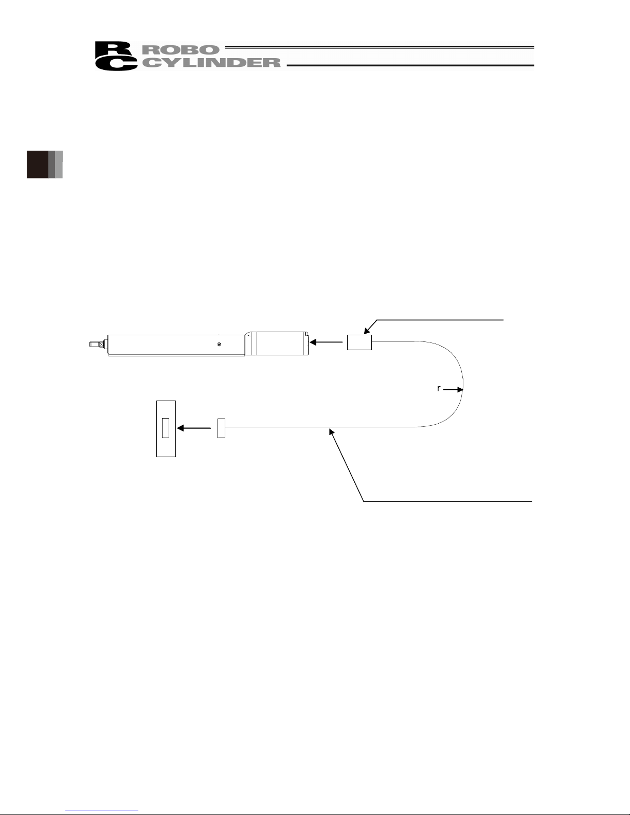
86
3.
Connecting with the Controller
3. Connecting with the Controller
As the connection cable for the controller and RCP6/RCP6S (this actuator), use the IAI-dedicated
controller and dedicated connection cable.
This section explains the wiring method for a single axis.
• If the dedicated connection cable cannot be secured, reduce the load on the cable by allowing it
to deflect only by the weight of the cable or wire it in a self-standing cable hose, etc., having a
large radius.
• Do not cut and reconnect the dedicated connection cable for extension or shorten the cable.
• Do not pull on the dedicated connection cable or bend it forcibly.
• The actuator cable coming out of the motor unit is not meant to be bent. Fix the cable so it would
not be bent repeatedly
Please consult with IAI if you require a different kind of cable than the one supplied.
Robot Cable
: 5m or below r = 68mm or more (use for operation)
: In the case of exceeding 5m
r = 73mm or more (use for operation)
Standard Cable
: 5m or below r = 85mm or more (use for operation)
: In the case of exceeding 5m
r = 91mm or more (use for operation)
Dedicated Controller
Dedicated Cable
RA4, RA6, RA7
· Motor Encoder Integrated Cables: CB-CAN-MPA□□□
· Motor Encoder Integrated Robot Cables:
CB-CAN-MPA□□□-RB
RA8
· Motor Encoder Integrated Cables: CB-CFA3-MPA□□□
· Motor Encoder Integrated Robot Cables:
CB-CFA3-MPA□□□-RB
* □□□ represents the cable length. The longest corresponds to 20m.
e.g.) 080 = 8m
RCP6- ××
Dedicated Connection Cable
(Connect RCP6 and dedicated controller)
· PCON-CB
· MCON
· MSEL

87
3. Connecting with the Controller
Warning: For wiring, please follow the warnings stated below. When constructing a system as the
machinery equipment, pay attention to the wiring and connection of each cable so they
are conducted properly. Not following them may cause not only a malfunction such as
cable breakage or connection failure, or an operation error, but also electric shock or
electric leakage, or may even cause a fire.
• Use dedicated cables of IAI indicated in this instruction manual. Contact us if you wish to have a
change to the specifications of the dedicated cables.
• Make sure to turn the power off in the process of power line or cable connection or
disconnection.
• Do not attempt to cut a dedicated cable with connectors on both ends to extend, shorten or
re-joint it.
• Hold the dedicated cable to avoid mechanical force being applied to the terminals and
connectors.
• Use a cable pipe or duct to have an appropriate protection when there is a possibility of
mechanical damage on a dedicated cable.
• In case a dedicated cable is to be used at a moving part, make sure to lay out the cable without
applying any force to pull the connector or extreme bend on the cable. Do not attempt to use the
cable with a bending radius below the allowable value.
• Make certain that the connectors are plugged properly. Insufficient connection may cause an
operation error, thus it is extremely risky.
• Do not lay out the cables to where the machine runs over them.
• Pay attention to the cable layout so it would not hit peripherals during an operation. In case it
does, have an appropriate protection such as a cable track.
• When a cable is used hanging on the ceiling, prevent an environment that the cable swings with
acceleration or wind velocity.
• Make sure there is not too much friction inside the cable storage equipment.
• Do not apply radiated heat to power line or cables.
• Do not bend the cable in the area from the connector tip inward to 150mm on both ends.
Motor • Encoder Integrated Cables CB-CAN-MPA□□□, CB-CFA3-MPA□□□
Motor • Encoder Integrated Cables Robot Type CB-CAN-MPA□□□-RB、
CB-CFA3-MPA□□□-RB
150mm
150mm

88
3.
Connecting with the Controller
• Have a sufficient radius for bending, and avoid a bend concentrating on one point.
• Do not let the cable bend, kink or twist.
• Do not pull the cable with a strong force.
• Pay attention not to concentrate the twisting force to one point on a cable.
• Do not pinch, drop a heavy object onto or cut the cable.
Steel Strap
(Piano Wire)
Tie them up
softly.

89
3. Connecting with the Controller
• When a cable is fastened to affix, make sure to have an appropriate force and do not tighten too
much.
• PIO line, communication line, power and driving lines are to be put separately from each other
and do not tie them together. Arrange so that such lines are independently routed in the duct.
Follow the instructions below when using a cable track.
• If there is an indication to the cable for the space factor in a cable track, refer to the wiring
instruction given by the supplier when storing the cable in the cable track.
• Avoid the cables to get twined or twisted in the cable track, and also to have the cables move
freely and do not tie them up. (Avoid tension being applied when the cables are bent.)
Do not pile up cables. It may cause faster abrasion of the sheaths or cable breakage.
Do not use spiral tube in
any position where cables
are bent frequently.
Duct
I/O Lines
(Flat Cable)
Power Line

90
4. Caution for Operation
4. Caution for Operation
• When you tighten the nut onto the tip bracket threaded part, hold a wrench to width across flat
part of the tip bracket with the rod in the most retracted state. Also, avoid that the load is applied
to the inside whirl-stop as you tighten the nut.
As a general rule, it cannot be used to apply a torque to the rod tip. Statically acceptable values
and the rod tip maximum displacement angles (initial value reference) expected at that time are
shown below. When the reaction force against the pressing operation is the side-way force,
make sure it would not exceed the allowable load.
• Do not apply radial load and load moment to the rod. Only the radial direction load that aligns with
the rod axis can be applied.
In the case that radial load and load moment cannot be avoided, attach an external guide (such
as a linear guide) in order not to apply any load other than radial direction load to the rod.
When the gravity center of work is on the rod axis on vertical motions, vibration may still be
generated by the clearance of internal whirl-stop. Attachment of an external guide is
recommended to suppress such vibration.
• When connecting the rod to external guides, be careful on the parallelism of the guides to the
rod. When connecting and fixing the rod to external guides, be careful not to apply excess
side-way load to the rod because of the assembly variation.
RA4 RA6 RA7 RA8
To[Nm] 1.0 1.5 2.5 5.0
θ[deg] ±1.0 ±1.0 ±0.8 ±0.8
External Guide

91
5. Maintenance and Inspection
5. Maintenance and Inspection
5.1 Inspection Items and Schedule
Follow the maintenance inspection schedule below.
It is assumed that the equipment is operating 8 hours per day.
If the equipment is running continuously night and day or otherwise running at a high operating
rate, inspect more often as needed.
External visual
inspection
Greasing
Start of work inspection ○
1 month inspection ○
3 month inspection ○
○(Rod sliding surface, Ball screw,
Whirl-stop)
Every 3 months thereafter ○ ○ (Rod sliding surface)
6 month inspection ○ ○(Ball screw, Whirl-stop)
Every 6 months thereafter ○ ○(Ball screw, Whirl-stop)
*1 Grease the rod sliding surface when grease is insufficient at start of work inspection, or every
three month. When greasing, always wipe off old grease before supplying new one.
The base oil may be separated from grease, depending on the installation orientation and
operating conditions. Perform visual inspection for any occurrence of drip.
Caution: • An actuator after 6 months of storage may have caused a degradation of the
grease.
Supply grease before start using. [Refer to 5.6 “Grease Supply”]
• Degradation speed of grease may differ depending on the environment of use
(temperature, humidity and ambient conditions). It is recommended to shorten
the grease supply period if the actuator is used under a bad condition such as
in high temperature, high humidity or in dusty ambience.
Also, it is recommended to improve the environment conditions in case the
grease changes its color due to the bad condition of use.

92
5. Maintenance and Inspection
5.2 External Visual Inspection
An external visual inspection should check the following things.
Main unit Loose actuator mounting bolts, other loose items
Rod sliding
surface
Lubrication state of grease
Drip of grease base oil or other oils
Adhesion of dust and other foreign objects
Cables Scratches, proper connections
Overall Irregular noise, vibration
5.3 Cleaning
• Clean exterior surfaces as necessary.
• If there are drips of grease base oil or other oils on the rod sliding surface and the surrounding
area, wipe off with with a soft cloth.
• Use a soft cloth to wipe away dirt and buildup.
• Do not blow too hard with compressed air as it may cause dust to get in through the gaps.
• Do not use oil-based solvents as they can harm lacquered and painted surfaces.
• To remove severe buildup, wipe gently with a soft cloth soaked in a neutral detergent or alcohol.
5.4 Grease Supply
5.4.1 What Grease to Use
IAI uses the following grease in our plant.
Ball screw Kyodo Yushi Multitemp LRL No.3
Whirl-stop Kyodo Yushi Multitemp LRL No.3
Rod (sliding surface) Kyodo Yushi Multitemp LRL No.3
Use lithium-based spray grease for maintenance.
Wako Chemical
Spray grease No.A161 or
equivalents
Warning: Never use anything other than synthetic poly-olefin grease. Mixing poly-grease
with other grease not only reduces the performance of the grease, it may even
cause damage to the actuator.
Rod Sliding Surface

93
5. Maintenance and Inspection
5.4.2 How to Apply Grease
(1) For RA4, remove slim hexagonal socket head bolts (M3 × 4) blocking the greasing port by
Allen wrench.
For RA6/RA7/RA8, remove the rubber cap blocking the greasing port.
(2) Grease the ball screws and the whirl-stop according to the following instructions.
[Ball Screw]
Adjust the rod to the home position.
By adjusting it to the home position, the greasing port and the port for ball screws will match
inside the main unit.
Connect the controller and adjust it to the home position.
Insert the tip of the spray grease in greasing port and inject it for one second.
One injection time should not exceed one second.
[Whirl-stop]
Adjust the rod position above 40mm.
Insert the tip of the spray grease in greasing port and inject it for one second.
One injection time should not exceed one second.
(3) Clean up the rod (sliding surface) and apply the grease with hands.
(4) After greasing, move the rod full-stroke to apply the grease thoroughly.
Caution: Supplying too much grease may increase sliding resistance and load to the motor,
resulting in a drop of performance.
・In case the grease got into your eye, immediately go see the doctor to get
appropriate care. After finishing the grease supply work, wash your hands
carefully with water and soap to rinse the grease OFF.
Rod Sliding
Surface
Rubber Cap
RA6/RA7/RA8
Slim Hexagonal
Socket Head Bolt
M3x4
RA4
 Loading...