

Page 1
Page 2
2
Safety Instructions
Warning : If user does not follow the instructions in this book properly, a serious injury, harm,
or death may occur to user.
Caution : If user does not follow the instructions in this book properly, an injury to user or
physical damage to the product may be occurred.
Electric Power
- Do not use any damaged power cord, plug, and loose outlet. It may cause an electric shock or fire.
- Make sure that the power plug is inserted firmly into the outlet so that the power cord does not
get loosed. A loose connection may cause a fire.
- Do not forcibly bend or pull the power cord or have it pressed under a heavy object.
It may cause an electric shock or fire.
- Do not handle the power cord with wet hands. It may cause an electric shock.
- Do not connect multiple electric devices to one outlet. It may cause an abnormal heat or fire.
- This product is not waterproof. Do not operate the product in a wet place in any case.
- Do not keep or operate the product in direct sunlight.
Page 3
3
Usage
- Do not assemble the product when you are tired or physically in a bad condition particularly
while intoxicated.
- Do not place your face too close to the robot.
- Do not use dangerous tools such as a knife or a drill but only recommended tool.
- Keep the remote control that contains batteries away from children’s reach.
- When your kid swallowed a battery, consult with a doctor immediately.
- Do not keep or operate the robot in a place of high temperature or humidity.
- Keep small parts such as bolts, nuts, and joints away from children’s reach.
- When your kid swallowed any product part, consult with a doctor immediately.
- Use the product only in an indoor environment.
- Do not disassemble, repair, and modify the product parts arbitrarily.
- Do not connect or disconnect cables while the robot product is in operation.
It may cause a damage or failure to the product.
- Make sure that only designated devices be connected to connectors or connection ports of the product.
It may cause a damage or failure to the product.
- When cleaning the product, do not use water or solvent such as benzene, and alcohol but use a soft
and dry cloth only. It may cause a failure to the product.
- Keep the robot well, or parts away from kid’s access.
Page 4

4
- Do not leave the product with power on. Battery damage may cause a product failure.
- Do not give excessive force while a torque is applied to the robot.
This could cause the gear damage of robot module and product failure.
- When robot gets twisted by running wrong motions while programming, turn the power off quickly to
prevent excessive torque from being transmitted to the robot.
- If your finger is put and pressed in between robot modules, turn the power off quickly and remove
force applied to robot to prevent any physical injury.
- Do not operate near in baby or animal. It may cause injury to the life or product failure.
Page 5
5
[ Notice for Assembly and Operation ]
· All users should follow the instructions in this user manual.
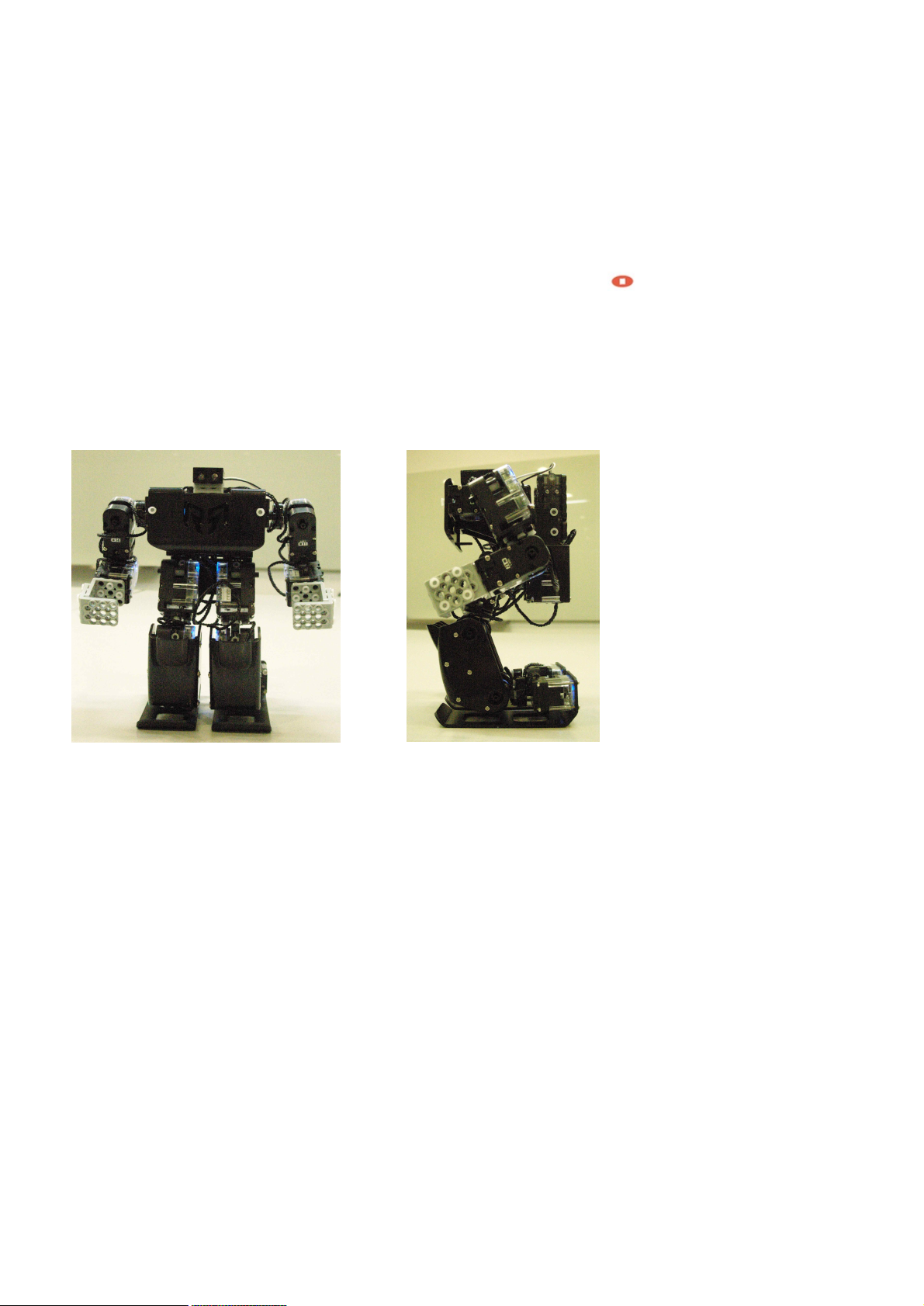
· The basic posture of standard platform (HUNO) robot is as shown in the below.
If robot does not take the posture as the below after you press the center ( ) button of
IR remote controller, it means that robot was assembled in wrong way.
Do not operate robot by force when robot was assembled in wrong way
Otherwise, robot could be damaged and it gets out of order.
· Sometimes, smart servo does not rotate well when you assemble it by hand.
This happens when internal gears are stiff, not a defective problem.
This kind of problem will be solved when robot took the basic posture after
you power-on smart controller.
· Generally, it takes about one hour to assemble it by using '+' screw driver.
But this is the average assembly time. so it can take longer or less depends on users' working environment.
· Robot will walk well in the flat place. It can be fallen down when you put a robot in carpet or rugged place
· Basic motions (11 motions) are already pre-programmed.
These motions are played by IR remote controller as soon as receiving robot.
. Make sure that nuts are not dropped into smart servo or smart controller during assembling robot.
Page 6

6
< Table of Contents >
1. Basic Instruction ................................................................................................................. 7
1.1 Product Introduction ................................................................................................................................... 7
1.2 Product Usage.............................................................................................................................................. 8
1.3 Rivet Tool.................................................................................................................................................... 12
2. RQ-HUNO Assembly Guide................................................................................................. 16
2.1 Check Part List...........................................................................................................................................16
2.2 Smart servo connection and set basic posture position ...................................................................... 17
2.3 Right LEG Assembly .................................................................................................................................. 19
2.4 LEFT LEG Assembly...................................................................................................................................24
2.5 RIGHT ARM Assembly............................................................................................................................... 29
2.6 LEFT ARM Assembly.................................................................................................................................. 32
2.7 BODY Assembly .........................................................................................................................................35
2.8 Check Assembled Robot ...........................................................................................................................49
3. Zero Position Adjustment .................................................................................................. 51
4. Download Cable (UART) driver Installation ....................................................................... 53
5. Download Tool................................................................................................................... 55
5.1 Introduction ............................................................................................................................................... 55
5.2 Download File............................................................................................................................................. 56
6. MotionBuilder .................................................................................................................... 59
6.1 Introduction ............................................................................................................................................... 59
6.2 Motion Programming #1 .......................................................................................................................... 62
6.3 Change Motion Speed............................................................................................................................... 68
6.4 Motion Programming #2 .......................................................................................................................... 69
7. ActionBuilder..................................................................................................................... 77
7.1 Introduction ............................................................................................................................................... 77
7.2 Action Programming #1 (Continuous Motions).....................................................................................79
7.3 Action Programming #1 (Using Sound Sensor)....................................................................................82
8. Appendix ........................................................................................................................... 86
8.1 Auto power-saving mode .........................................................................................................................86
8.2 How to change Smart Servo ID Number ............................................................................................... 87
8.3 How to charge............................................................................................................................................ 89
Page 7

7
1. Basic Instruction
1.1 Product Introduction
RQ HUNO Kit is a new robotic DIY kit designed to provide robot enthusiasts with the value of Education
and Entertainment. Design and build various robots simply by plugging together block-type robotic
actuator modules. Without programming, users can download robotic motion files from the internet and
play them on the RoboBuilder RQ platforms.
FEATURES
Quick & Simple Assembly : It can be assembled within one hour.
Robot File Sharing : Robot file can be shared via Internet. World First File Sharing by Precise Motion
Control Technology.
Joint-Insert Style Assembly : Easily connected between modules by using provided various Joint.
Elaborate Motion : The angle of smart servo module can be adjusted freely, therefore, motion is
smooth and natural. - Wheel Mode (360˚), Position Control Mode (0~332˚)
Individual Controller : RQ HUNO Smart Controller and Smart Servo module controller are separated,
therefore, it is easy to upgrade and easy to find failure.
Built-in Connector : Signal line and power line can be connected directly onto Smart Servo module.
Unbounded Free Assembly Style : It can be built into various robot style, besides standard platform.
Page 8
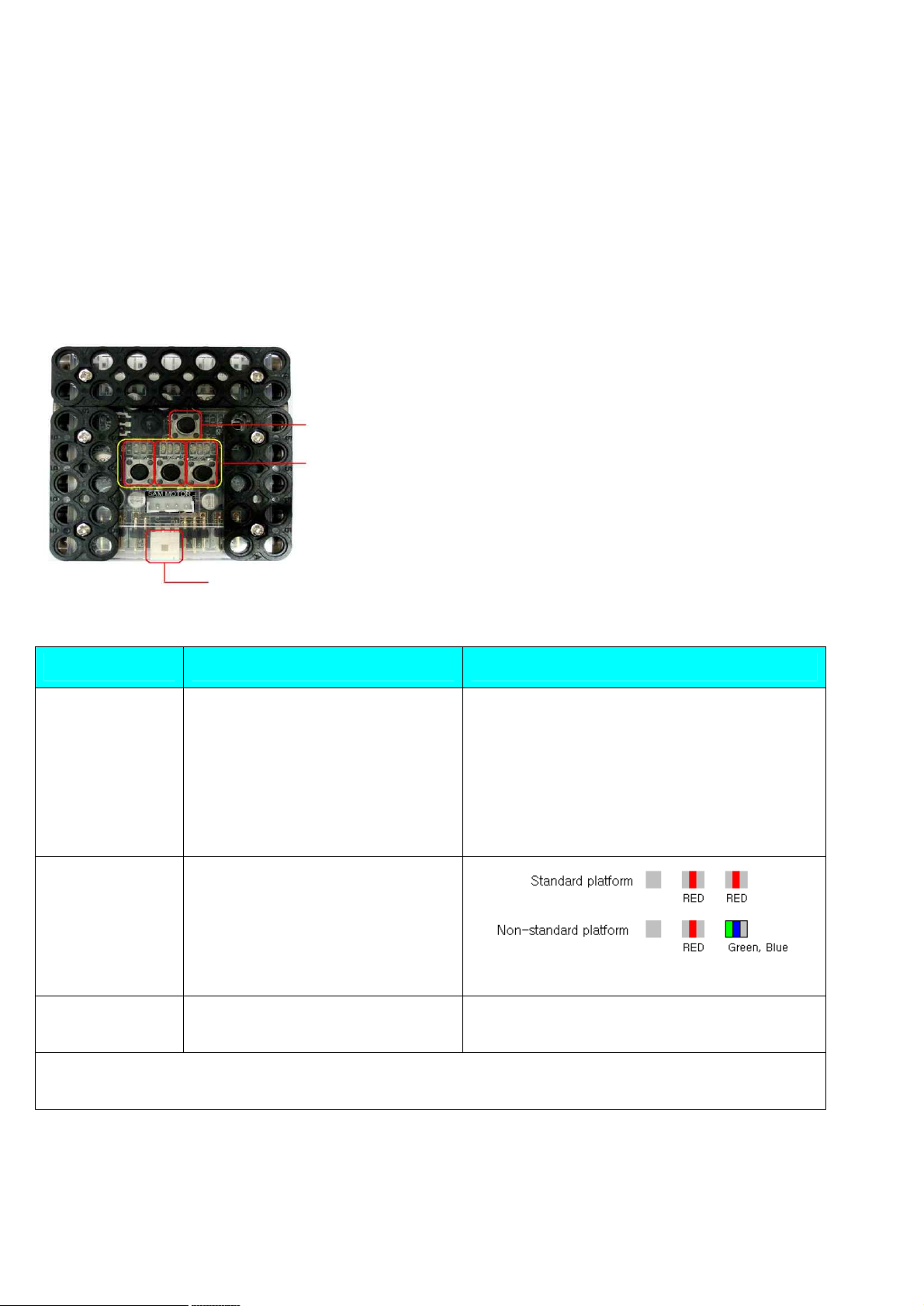
8
Function Manipulation Descriptions
Power On Connect battery line to Power
Connector and press
Button P.
LED indicates “STOP” state.
(“STOP” state means LED lights
but is NOT blinking.)
- It sets the latest platform.
- It sets Standard platform,
Non-standard platform, Zero position
setting.
Platform
Selection
Press button 3 in order to set
“Standard platform” and “Nonstandard platform”
in “STOP” state. (RQ-HUNO is
standard platform.)
Power Off Press button P more than
5 seconds.
All LEDs are off.
For more information, see the next page.
1.2 Product Usage
Operating Smart Controller
By manipulating the smart controller, you can select proper robot platform, and play motions. Also, you
can change into various mode (such as PC direct control mode or firmware upgrade mode).
버 Button P : Power (ON/OFF) button / Run button
In smart controller, ‘1’, ‘2’, ‘3’ numbers are written.
Below in each number, there are “button 1, button 2 and button 3”.
Above in each number, there are “LED 1, LED 2, LED 3”.
Power Connector
Page 9
9
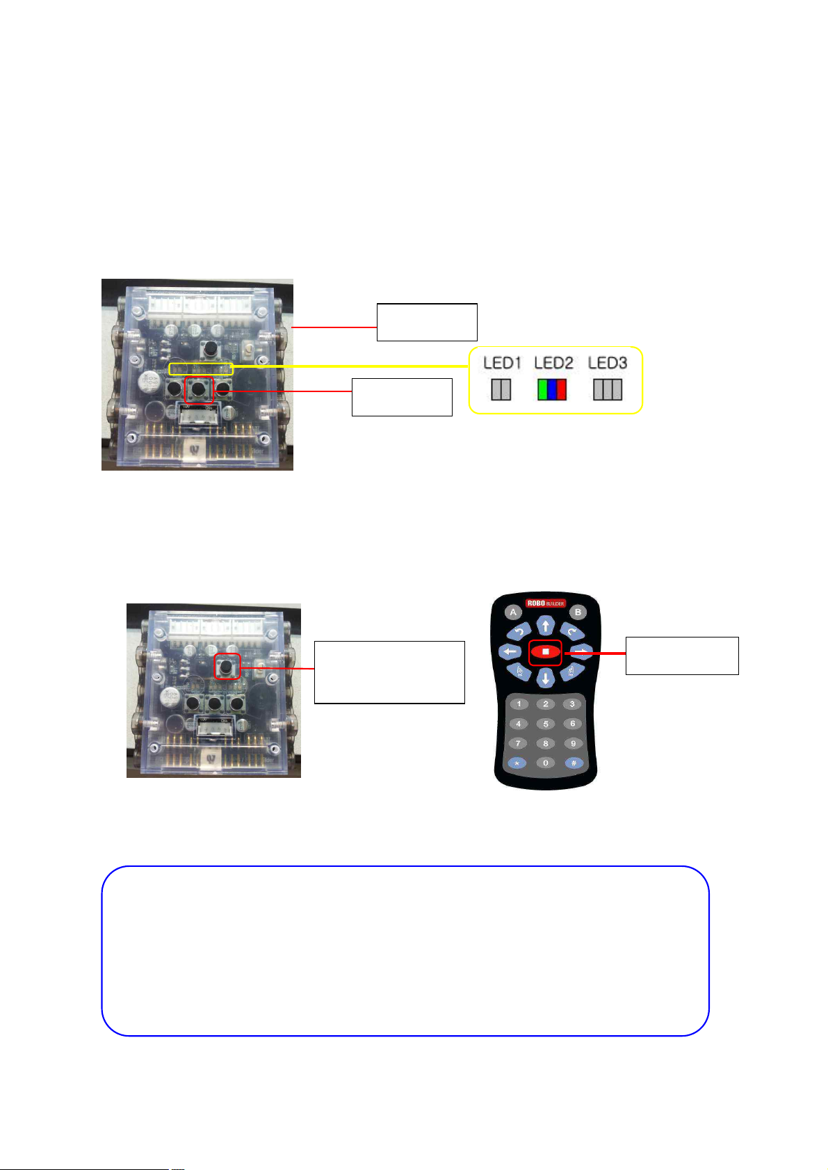
Button P
Button 2
IR remote controller
receiver
STOP button
IR remote controller registration
① Power-off the smart controller.
② Press button 2 then, press button P concurrently.
→ You can see LED2 - Green, Blue and Red lights together.
2
③ Make the IR remote controller close to smart controller towards <IR remote controller receiver>.
④ Press "stop" button in IR remote controller, then LED 2 "Green, Blue and Red" light will be blinking
three times. Now IR remote controller is registered.
※ NOTE
‣ Unregistered remote controller can not control the smart controller.
‣ Each smart controller can memorize 5 remote controller in maximum. If you try to
register 6th remote controller, then 1st registered remote controller is deleted.
‣ For the next remote controller registration, you can repeat the above procedures.
Page 10
10
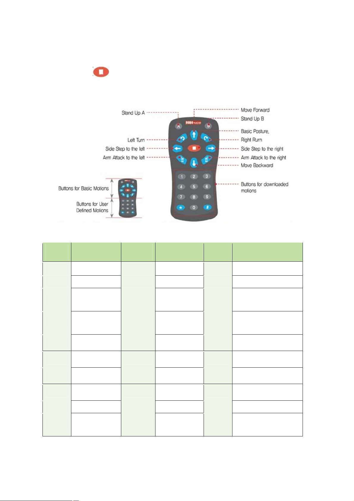
IR Remote Controller
Button Motion Button Motion Button Melody
1 Run Motion 1. # + 1 Run Action 1. * + 1
Ten little Indians
2 Run Motion 2. # + 2 Run Action 2. * + 2
Greeting
3 Run Motion 3. # + 3 Run Action 3. * + 3
Twinkle twinkle
Little star
4 Run Motion 4. # + 4 Run Action 4. * + 4
Head and shoulder
knees and toes
5 Run Motion 5. # + 5 Run Action 5. * + 5
Fur Elise
6 Run Motion 6. # + 6 Run Action 6. * + 6
Minuet(Mach)
7 Run Motion 7. # + 7 Run Action 7. * + 7
Congratulation
8 Run Motion 8. # + 8 Run Action 8. * + 8
Happy Birthday
9 Run Motion 9. # + 9 Run Action 9. * + 9
Arirang
0 Run Motion 10 # + 0
Run Action
10.
* + 0 Stop melody
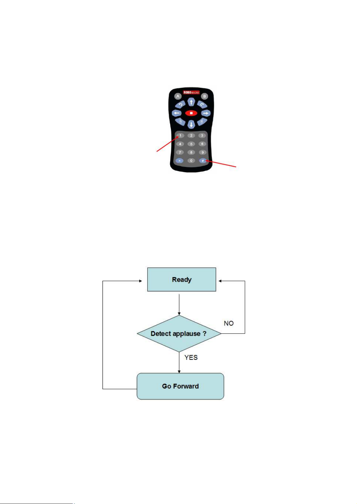
The best way to use the remote control is to have remote controller point to the center of smart
controller. Press STOP ( ) button whenever power on RQ smart controller first to take the basic
posture. Otherwise, IR remote controller button would not work on robot.
* Motions and Actions are downloaded by users
Page 11
11
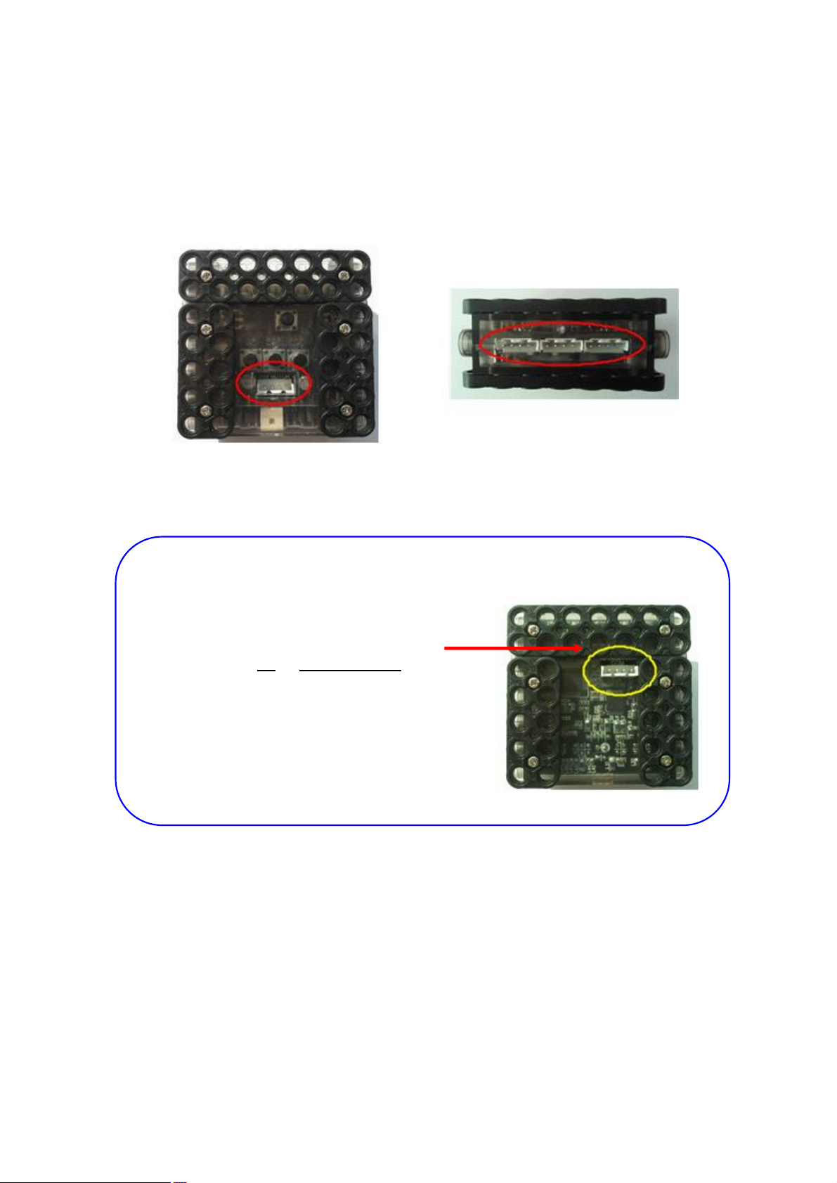
W Cable and Smart Controller connection
Smart controller has four port to connect for smart servo by using “W cable”.
You can connect any port regardless smart servo IDs.
* NOTE
Rear side of COM port is for connection
with PC or Bluetooth chip.
Page 12
12
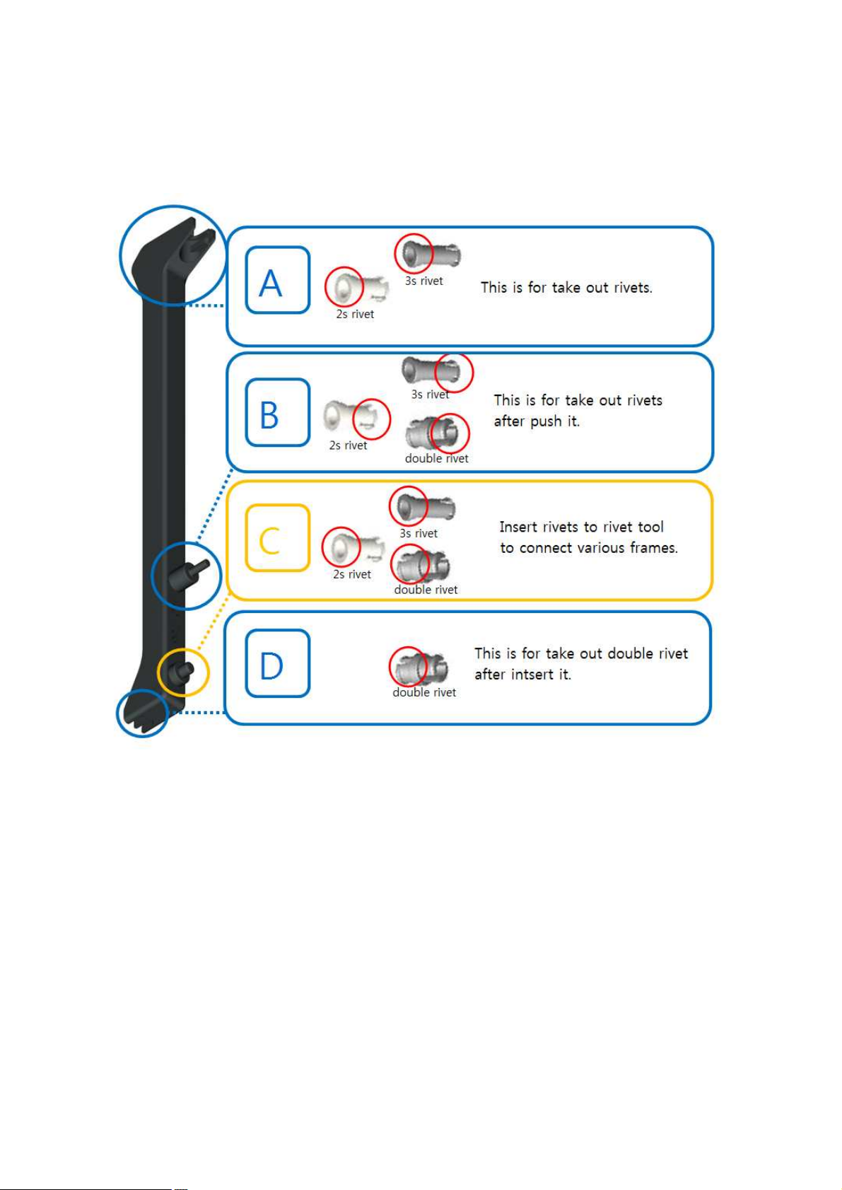
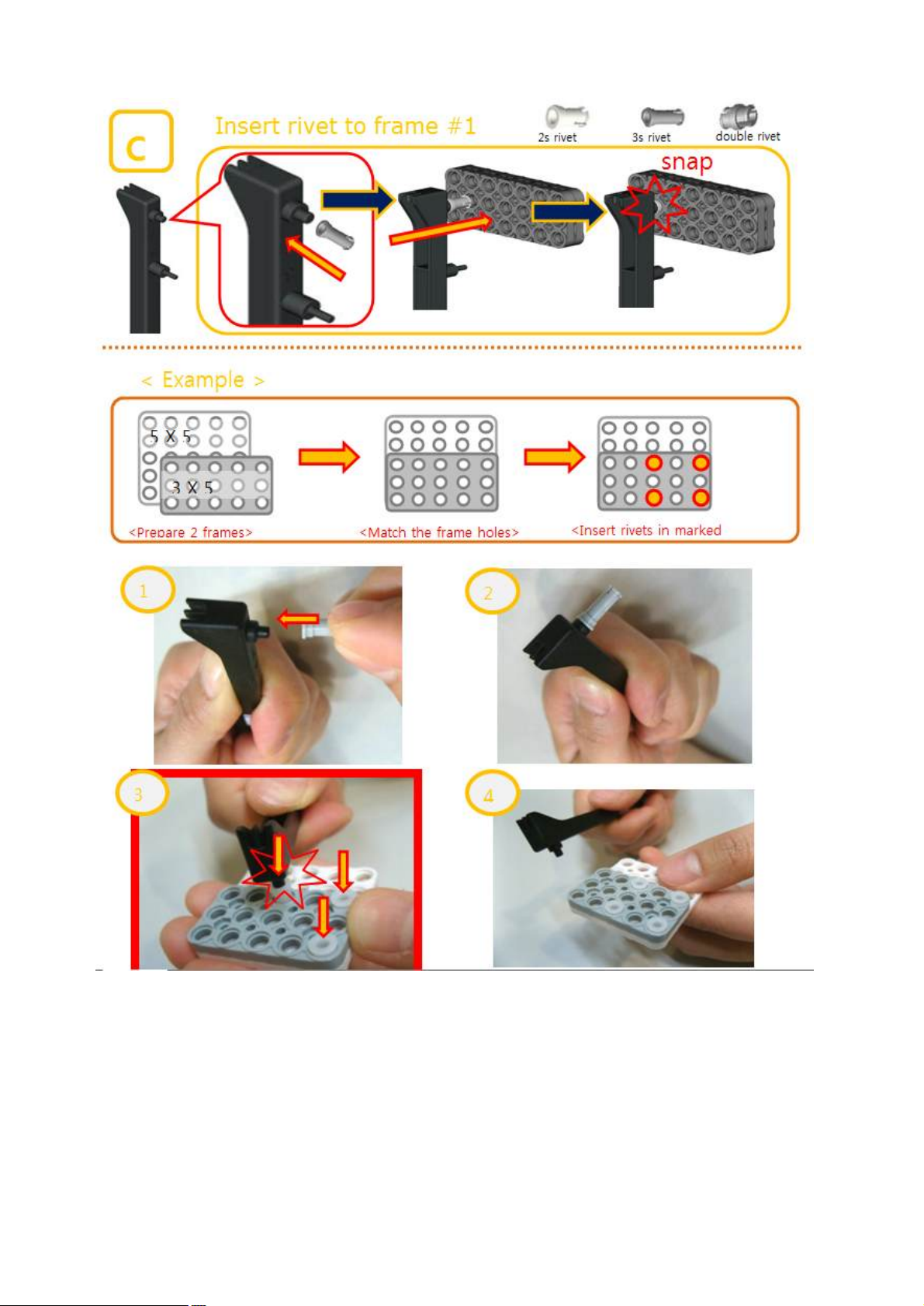
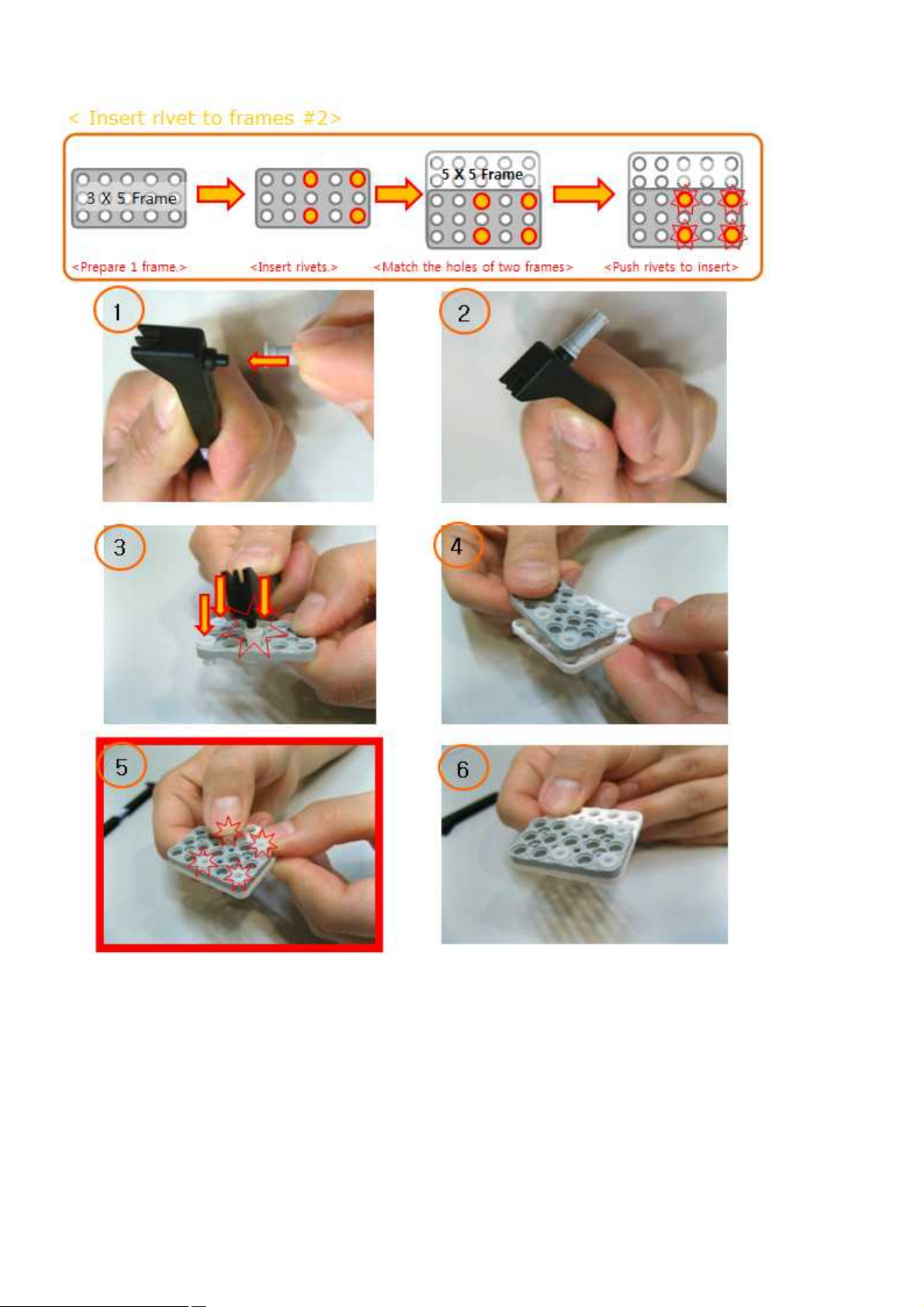
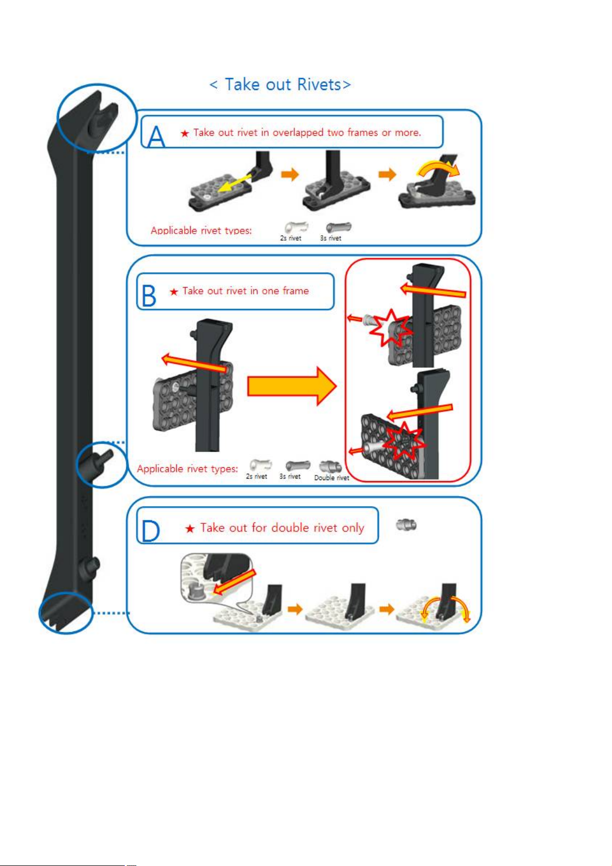
1.3 Rivet Tool
* Rivet Tool Usage
Page 13
13
Page 14
14 15 16
Page 15
Page 16
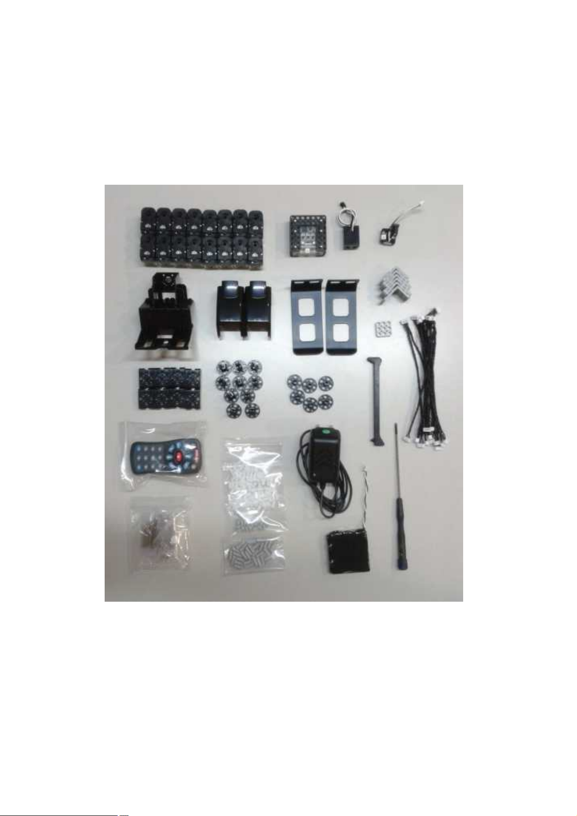
2. RQ-HUNO Assembly Guide
2.1 Check Part List
Place all the parts as the below for RQ-HUNO assembly.
Page 17
17
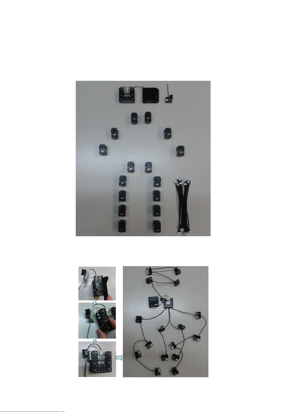
2.2 Smart servo connection and set basic posture position
Set up the RQ-HUNO initial position value in advance before you assembly.
This prevents confusion of smart servo position when you connect joint frame with smart servo.
1. Place all smart servos and other parts as the below.
2. Connect smart servo with the other smart servo by using “w Cable”, then also connect to smart
controller at the end as the below.
Page 18
18
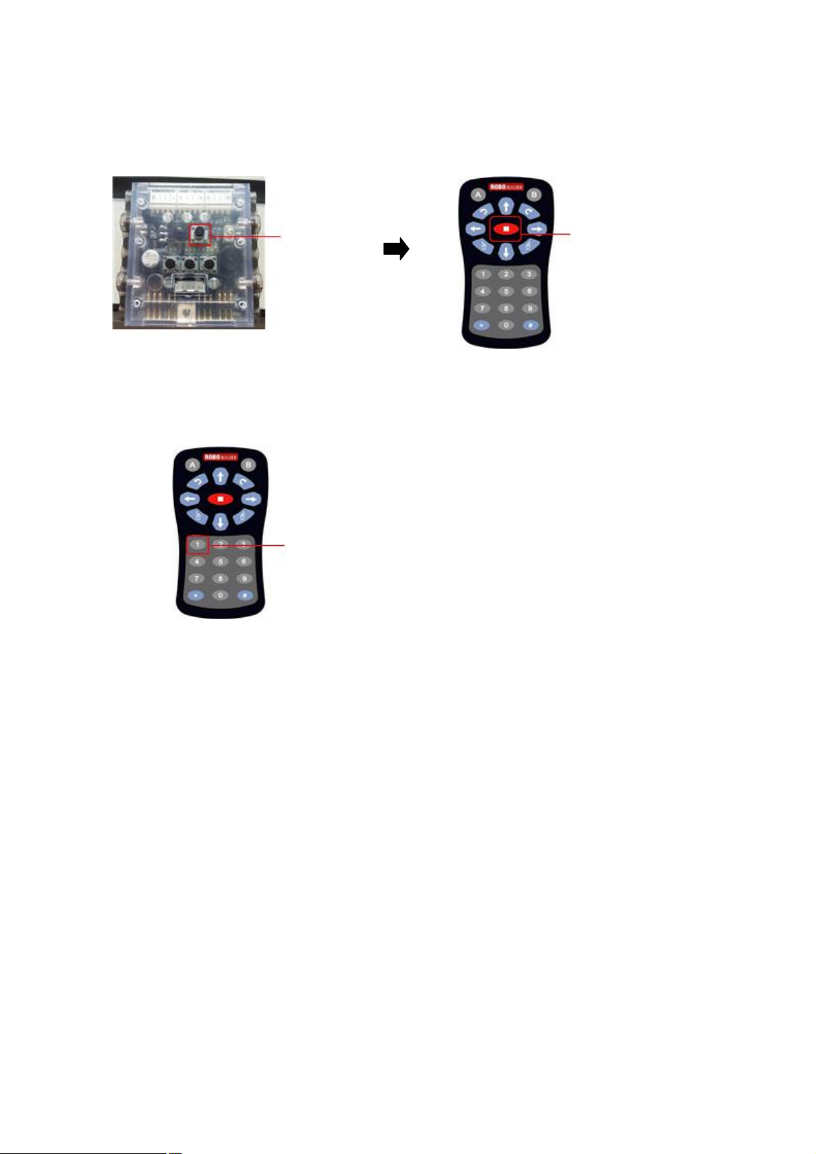
3. After power-on smart controller (it is “stop” state), press STOP button of IR remote controller.
If IR remote controller is not working, check whether IR remote controller is registered.
(See the page 8 - IR remote controller registration)
Button P STOP button
4. Press button 1 in IR remote controller.
Button 1
Each smart servo set initial position after the above procedures.
Now, disconnect all the “w Cables” from the smart servos and smart controller in order to assemble
RQ HUNO robot from the “RIGHT LEG ASSEMBLY”.
Page 19
19
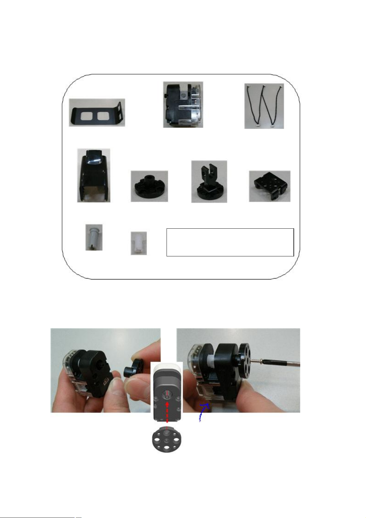
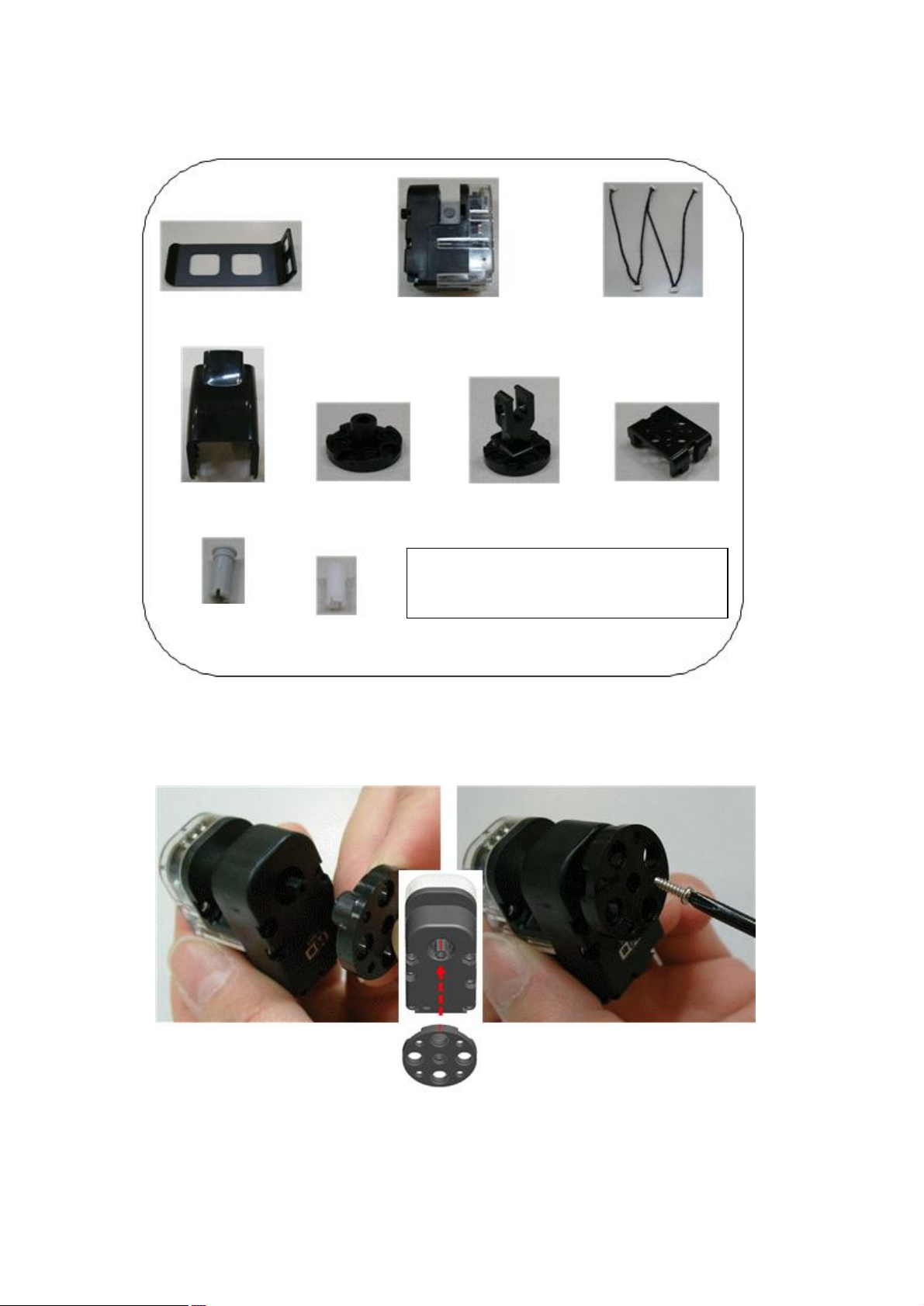
2.3 Right LEG Assembly
Foot Frame
Smart Servo * 4
(ID 06, 07, 08, 09)
W Cable * 1
Knee Frame * 1
Front Horn * 1
Joint Frame * 2
‘U’ Frame * 1
3s rivet * 2
2s rivet * 8
Screw (P6) * 1, Bolt (B12) * 1
Bolt(B27)*4, Bolt (B35) *5, NUT * 10
Front horn chase mark
should be in center position
(12 o’clock direction)
Be careful that smart servo initial
position should not be rotated
when you put screw into front
STEP1. Insert front horn to smart servo ID09, then fix it with screw (P6).
Before insert front horn to smart servo, check the chase mark as the below.
Page 20
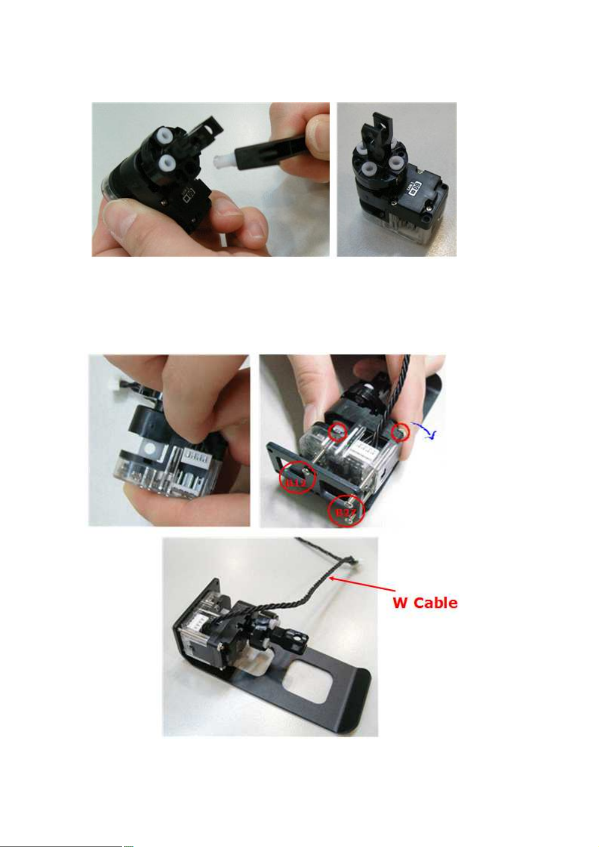
20
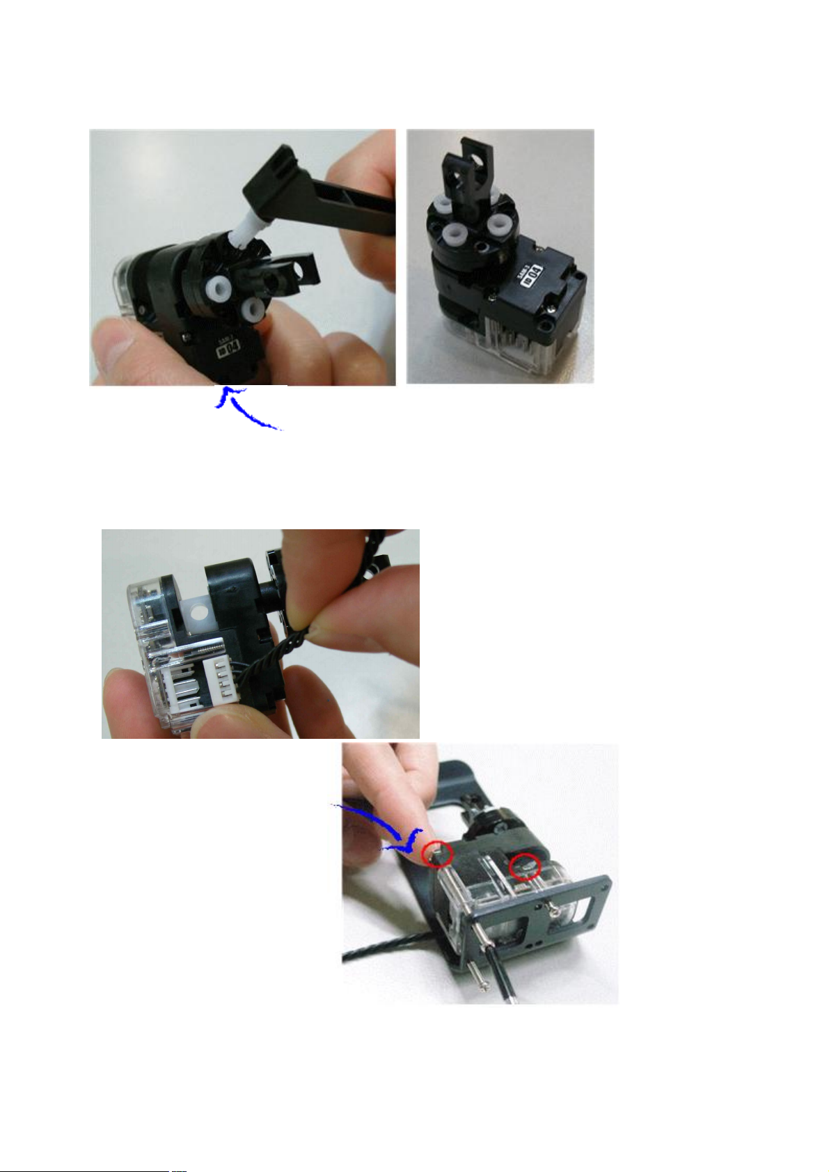
STEP2. Insert “2s rivet” to the “Joint Frame” to connect with “Front Horn”.
STEP3. Connect W Cable into smart servo “ID09” first, then connect foot frame by using Bolt and Nut.
(Left) Foot Frame and (Right) Foot Frame is same.
Page 21
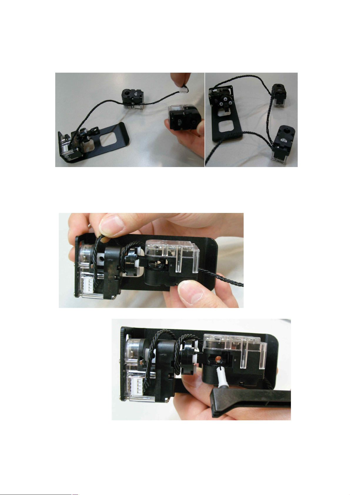
21
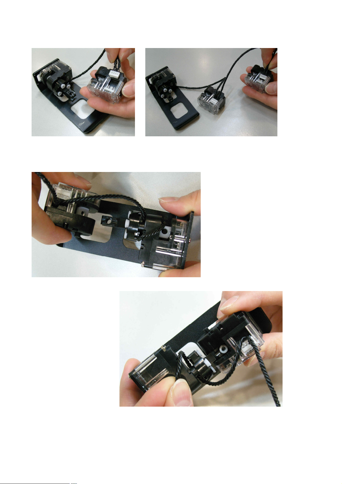
STEP4. Connect W Cable (that is already connected with ID09) with smart servo ID08 and ID07.
STEP5. Connect ID09 and ID08 by using “3s rivet”. Rotate W Cable one time and fix it.
Page 22
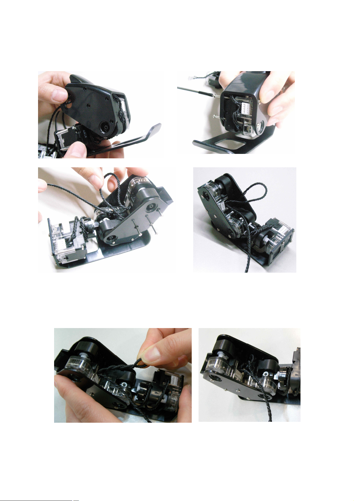
22
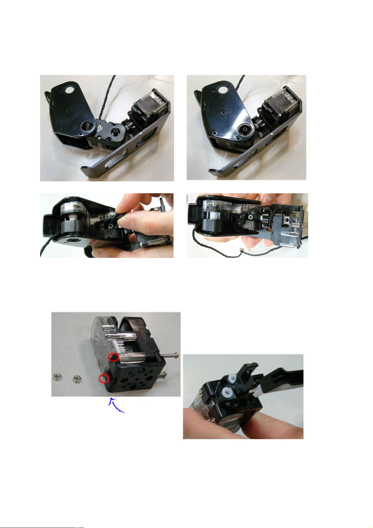
STEP6. Use the Bolt (B35) and Nut to connect “ID08” and “ID07” with “Knee Frame”.
STEP7. Twist cable 3~4 times between “ID08” and “ID07” and put into empty space.
Page 23
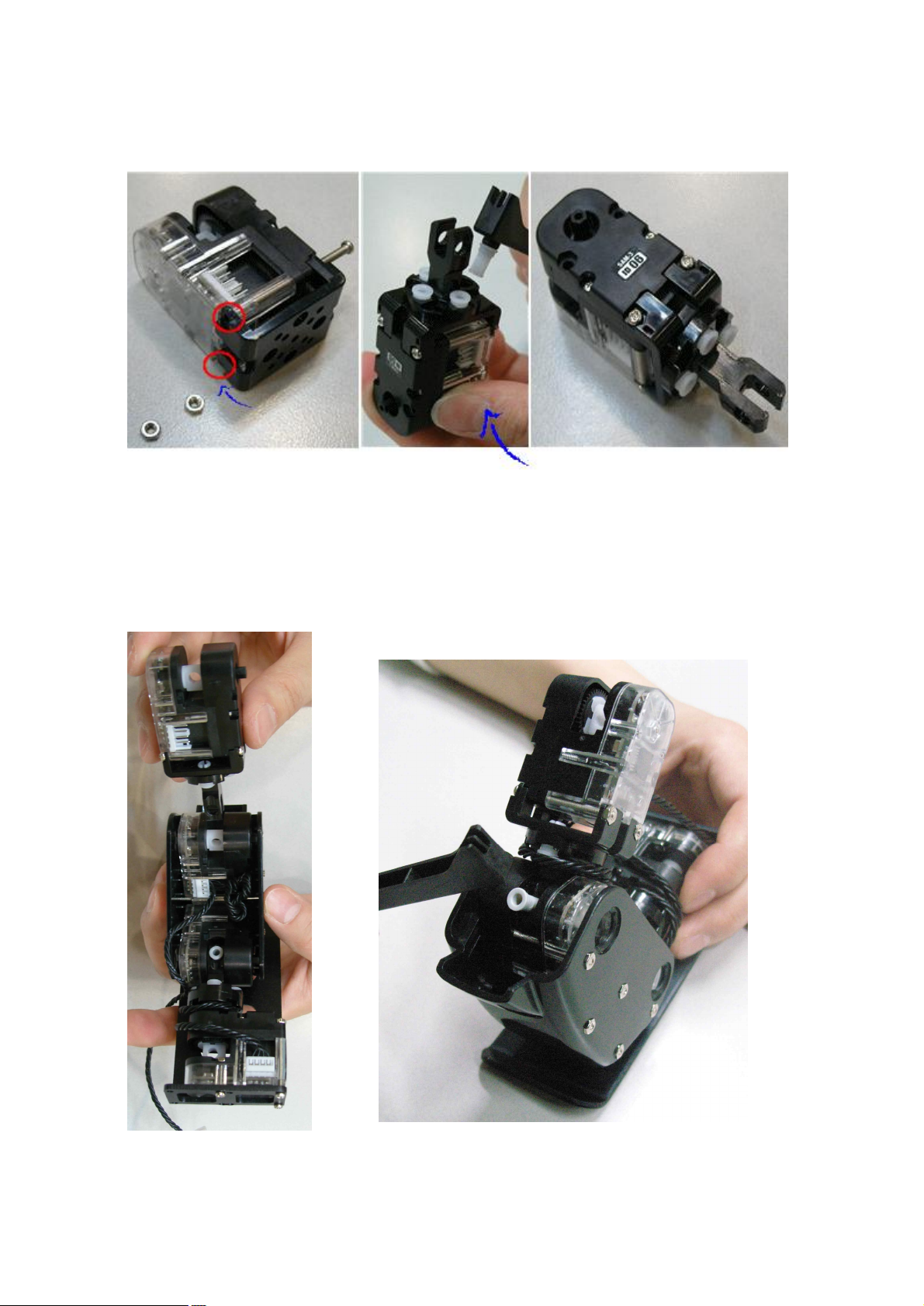
23
STEP8. Connect ID06 and ‘U’ frame by using Bolt (B27) and Nut. Then use the “2s rivet” to fix with “Joint
NUT
Be careful JOINT frame direction
Frame”.
STEP9. Connect ID07 with “Joint Frame” by using “3s rivet”. Rotate W cable two times and connect to ID06.
Page 24
24
2.4 LEFT LEG Assembly
Foot Frame
Smart Servo * 4
(ID 01, 02, 03, 04)
W Cable * 1
Knee Frame * 1
Front Horn * 1
Joint Frame * 2
‘U’ Frame * 1
3s rivet * 2
2s rivet * 8
Screw (P6) * 1, Bolt (B12) * 1
Bolt(B27)*4, Bolt (B35) *5, NUT * 10
Front horn chase mark
should be in center position
(12 o’clock direction)
STEP1. Connect Front Horn to smart servo “ID04” by using screw (P6).
Page 25
25
STEP2. Connect Front Horn and Joint Frame by using 2s rivets.
⇦ W Cable connection to ID04
NUT connect position
Be careful with Joint Frame direction.
STEP3. Insert “W Cable” with ID04, then connect Foot Frame by using Bolt(B12, B27) and Nut.
Page 26
26
STEP4. Connect W Cable with ID03 and ID02.
STEP5. Connect “Joint Frame” with ID03 by using 3s rivet. Then, rotate W Cable1~2 times and fix it.
Page 27
27
STEP6. Connect ID03 and ID02 with “Knee Frame” by using Bolt (B35) and Nut. Then, rotate the W Cable
NUT
Be careful JOINT frame direction
3~4 times and put into empty space.
STEP7. Connect ID01 and ‘U’ frame by using Bolt (B27). Then use the 2s rivet to fix with “Joint Frame”.
Page 28
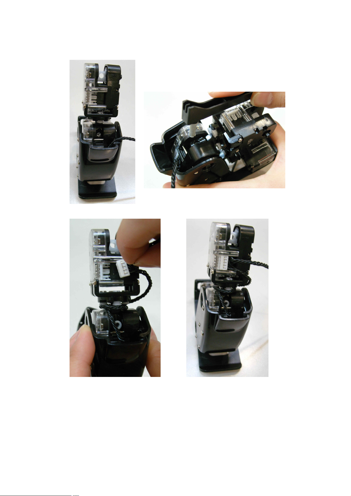
28
STEP8. Connect ID02 and “Joint Frame” by using “3s rivet”.
Then, rotate “W Cable” two times and connect with ID01.
Page 29
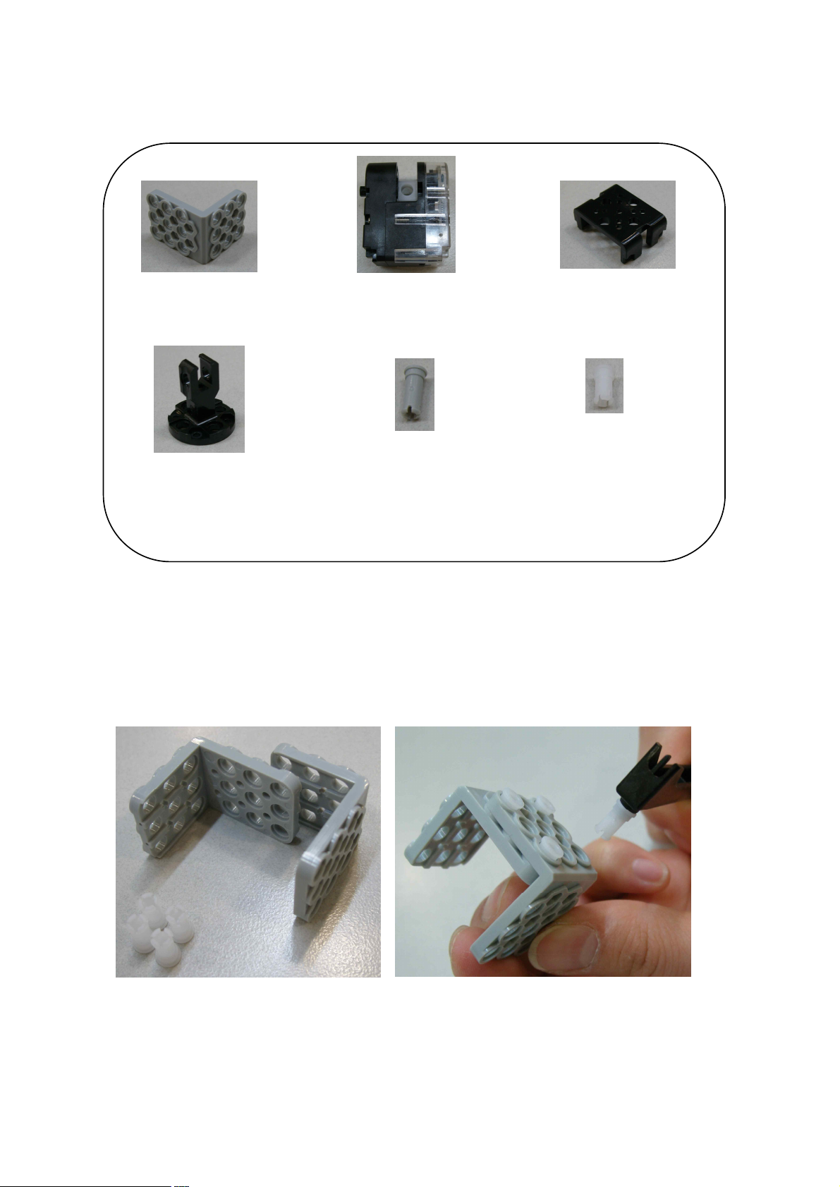
29
2.5 RIGHT ARM Assembly
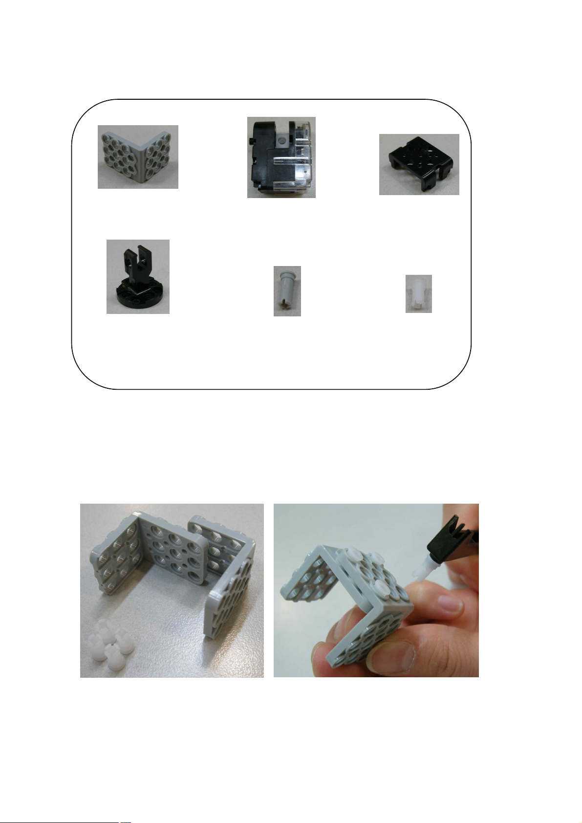
3*6 L type Frameⅹ2 Smart Servoⅹ2(ID14, ID15) ‘U’ Frame x 2
Joint Frameⅹ1 3s rivetⅹ1 2s rivetⅹ12
Bolt (B27) x 4, NUT x 4
STEP1. Make “Hand” part by using the two “3*6 L type Frame” and “2s rivets” as shown in the below.
Becareful with “3*6 L type Frame” part direction because the both sides are not same.
Page 30
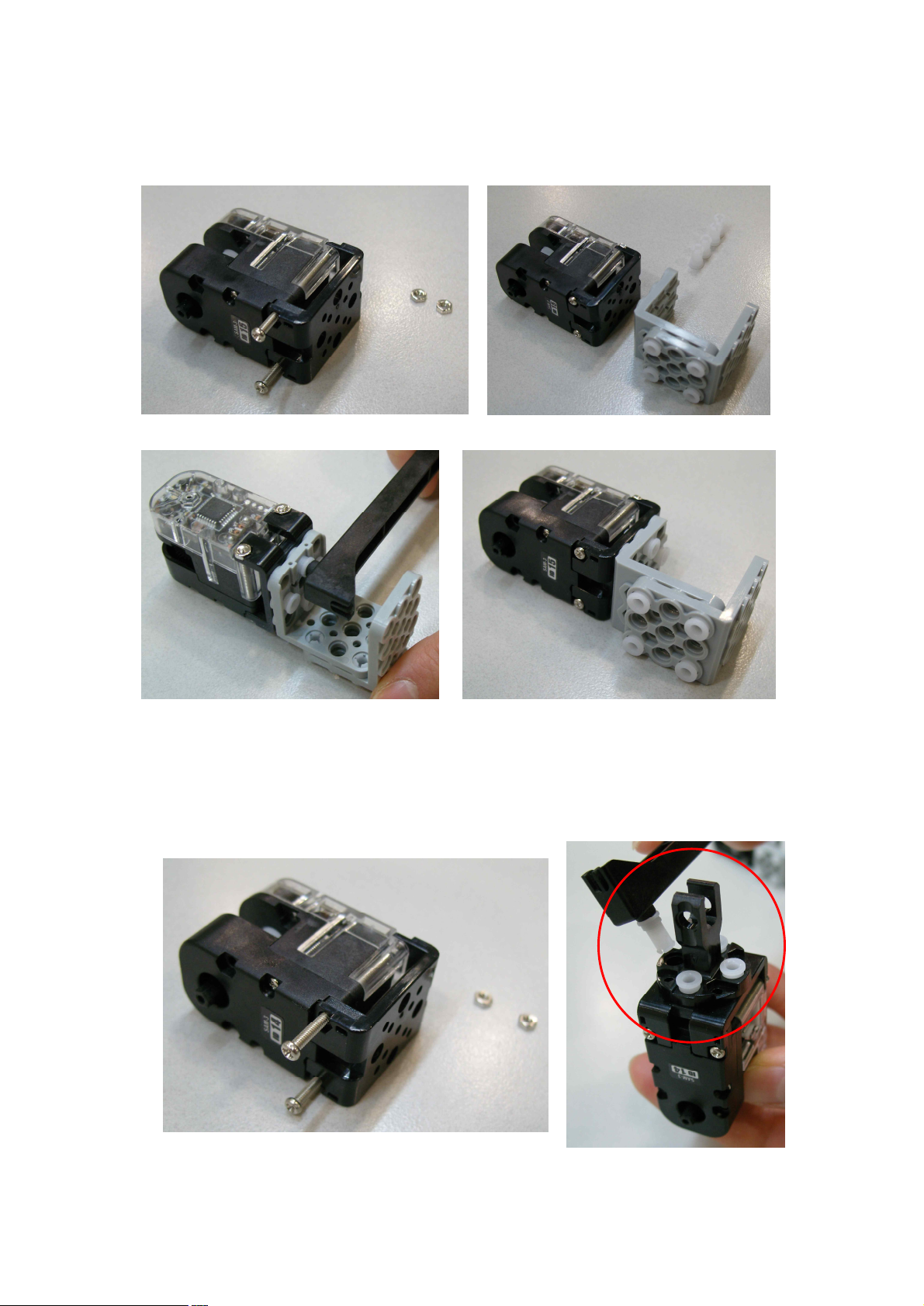
30
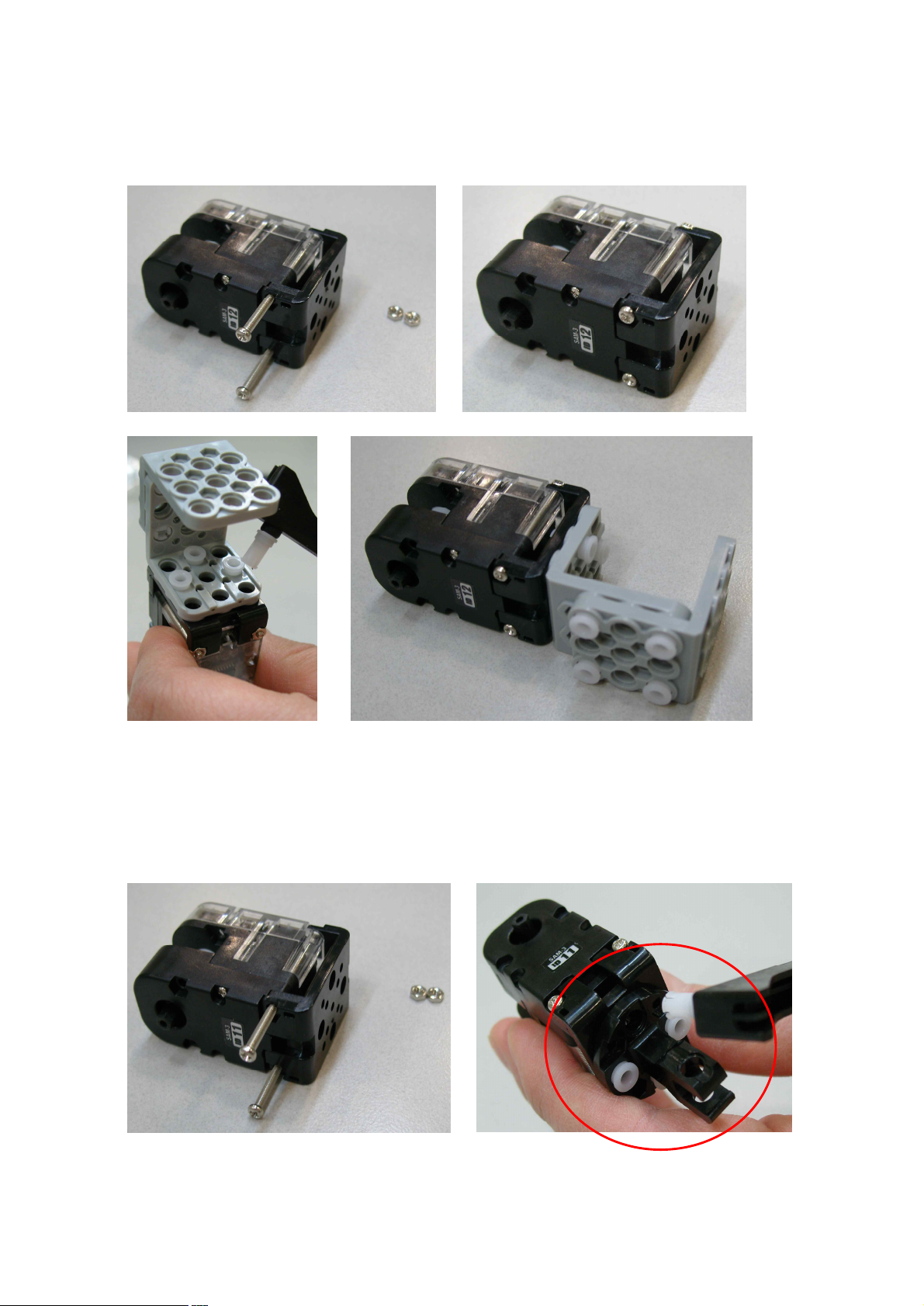
STEP2. Connect ID15 and ‘U’ Frame by using Bolt (B27) and Nut, then connect with “Hand” part by using
2s rivets.
STEP3. Connect ID14 and ‘U’ Frame by using Bolt (B27) and Nut, then, connect with Joint Frame.
Be careful of Joint Frame direction when you connect with smart servo.
Page 31
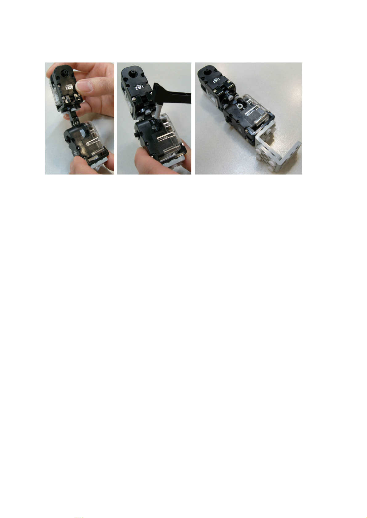
31
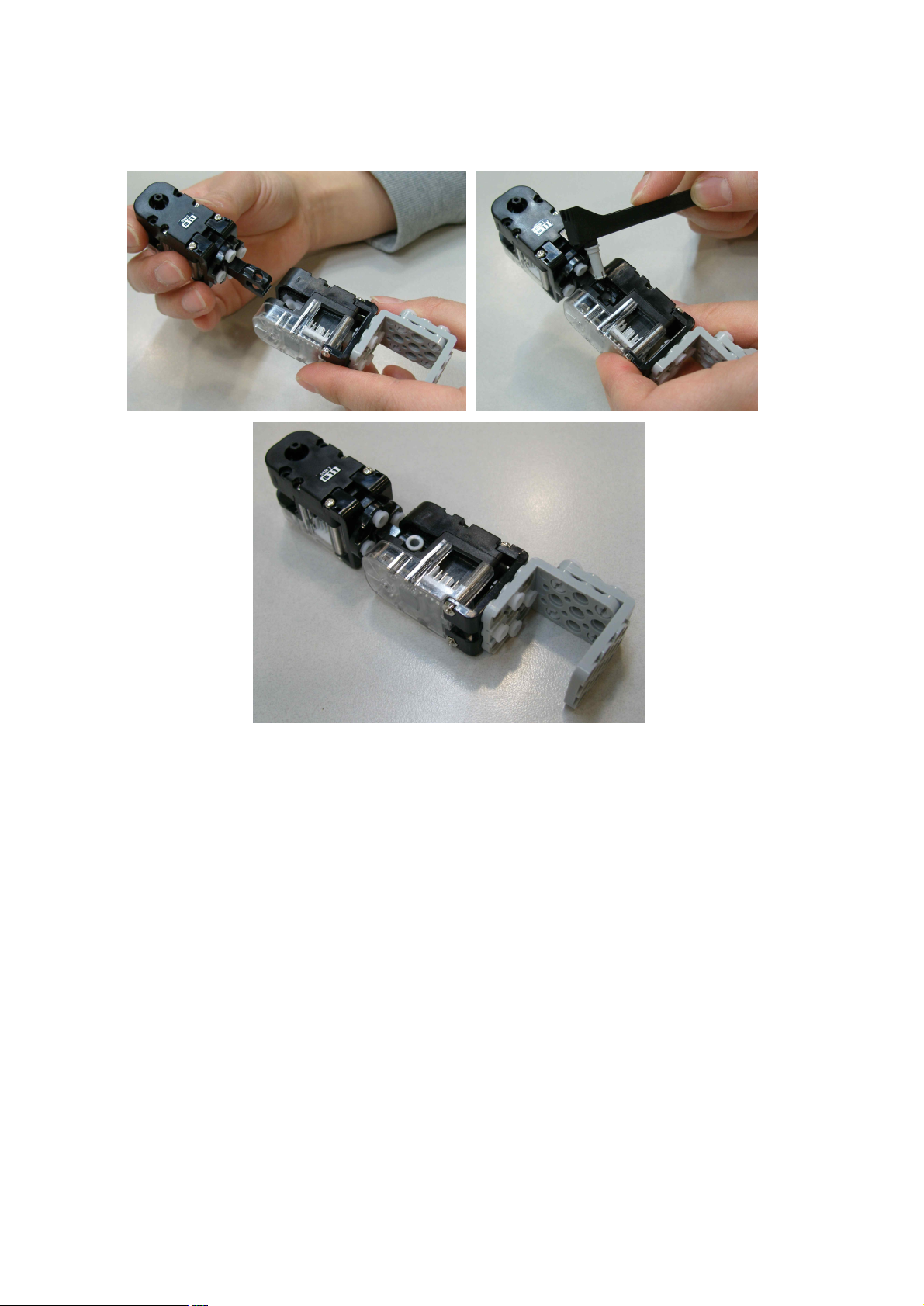
STEP4. Connect “Joint Frame” that connected with ID14 and ID15 by using 3s rivet.
Page 32
32
2.6 LEFT ARM Assembly
3*6 L type Frameⅹ2 Smart Servoⅹ2(ID11, ID12) ‘U’ Frame x 2
Joint Frameⅹ1 3s rivetⅹ1 2s rivetⅹ12
Bolt (B27) x 4, NUT x 4
STEP1. Make “Hand” part by using the two 3*6 L type Frame and “2s rivets” as shown in the below.
Becareful with 3*6 L type Frame part direction because the both sides are not same.
Page 33
33
STEP2. Connect ID12 and ‘U’ Frame by using Bolt (B27) and Nut, then connect with “Hand” part by using
2s rivets.
STEP3. Connect ID11 and ‘U’ Frame by using Bolt (B27) and Nut, then, connect with Joint Frame.
Be careful of Joint Frame direction when you connect with smart servo.
Page 34
34
STEP4. Connect Joint Frame that connected with ID14 and ID15 by using 3s rivet.
Page 35
35
2.7 BODY Assembly
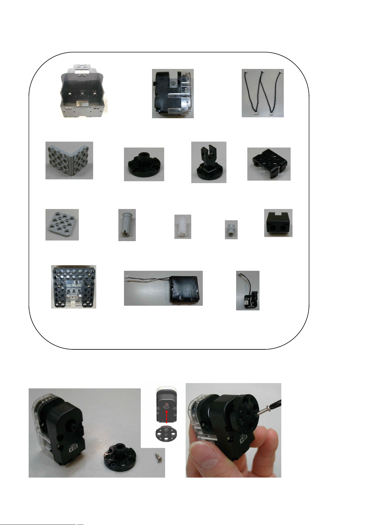
Front horn chase mark should be in center position (12 o’clock direction)
Body Frameⅹ1 Smart Servoⅹ4(ID00, ID05, ID10, ID13) W Cable x 2
3*6 L type Frameⅹ2 Front Hornⅹ4 Joint Frameⅹ4 U Frameⅹ2
3*3 Frameⅹ1 3s rivetⅹ8 2s rivetⅹ20 double rivetⅹ10 IRⅹ1
Smart Controllerⅹ1 Li-Poly Batteryⅹ1 Charging Board*1
Screw(P6)ⅹ4, Bolt (B6)ⅹ2, Bolt (B27)ⅹ4, Bolt (B30)ⅹ4, Nutⅹ10
STEP1. Connect Front Horn to ID05 by using screw (P6).
Page 36
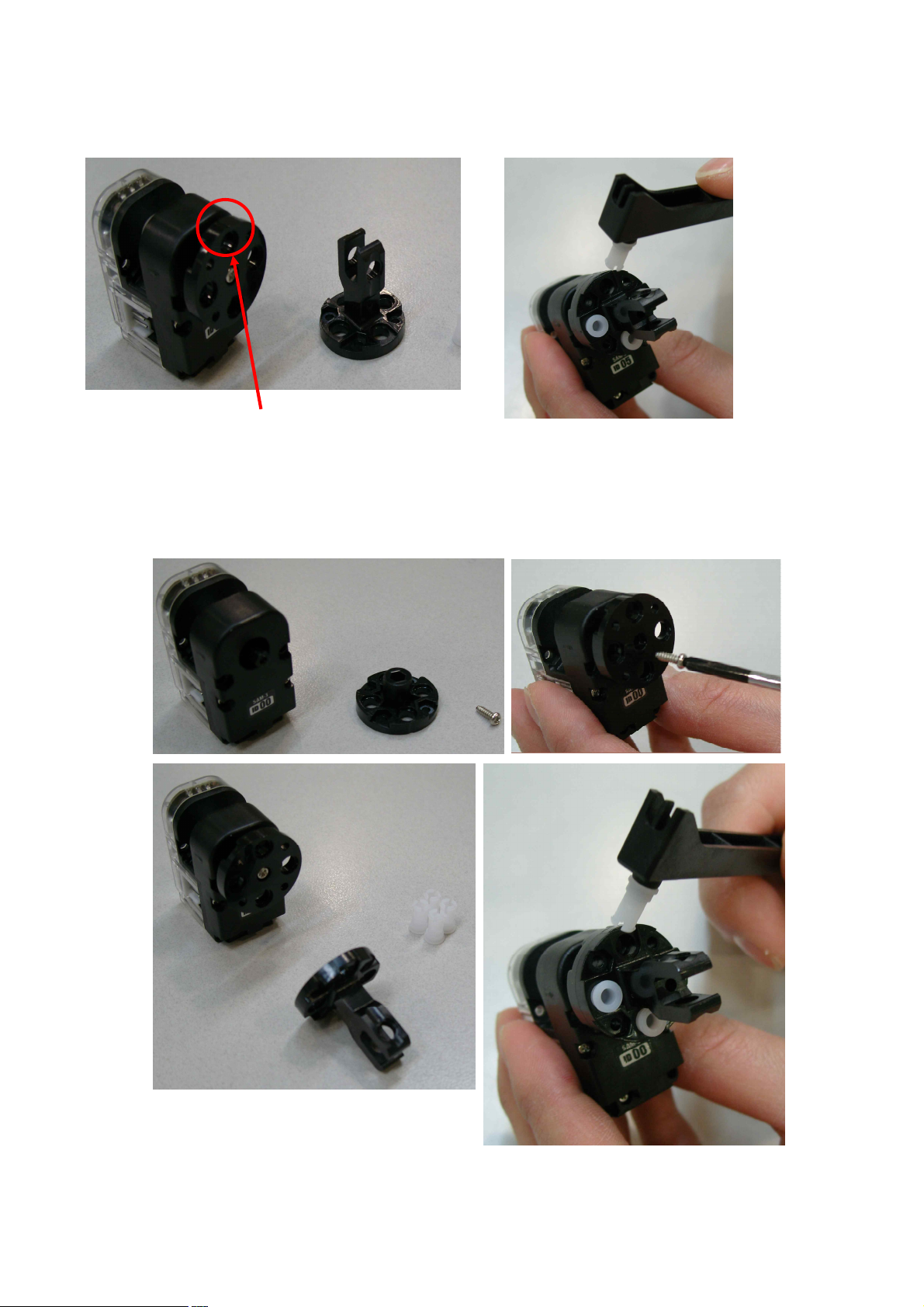
36
STEP2. Connect “Front Horn” and “Joint Frame” by using “2s rivet” as the below.
Front horn chase mark should be in center position (12 o’clock direction)
STEP3. Connect Front Horn and Joint Frame with ID00 same as the ID05 connection.
Page 37
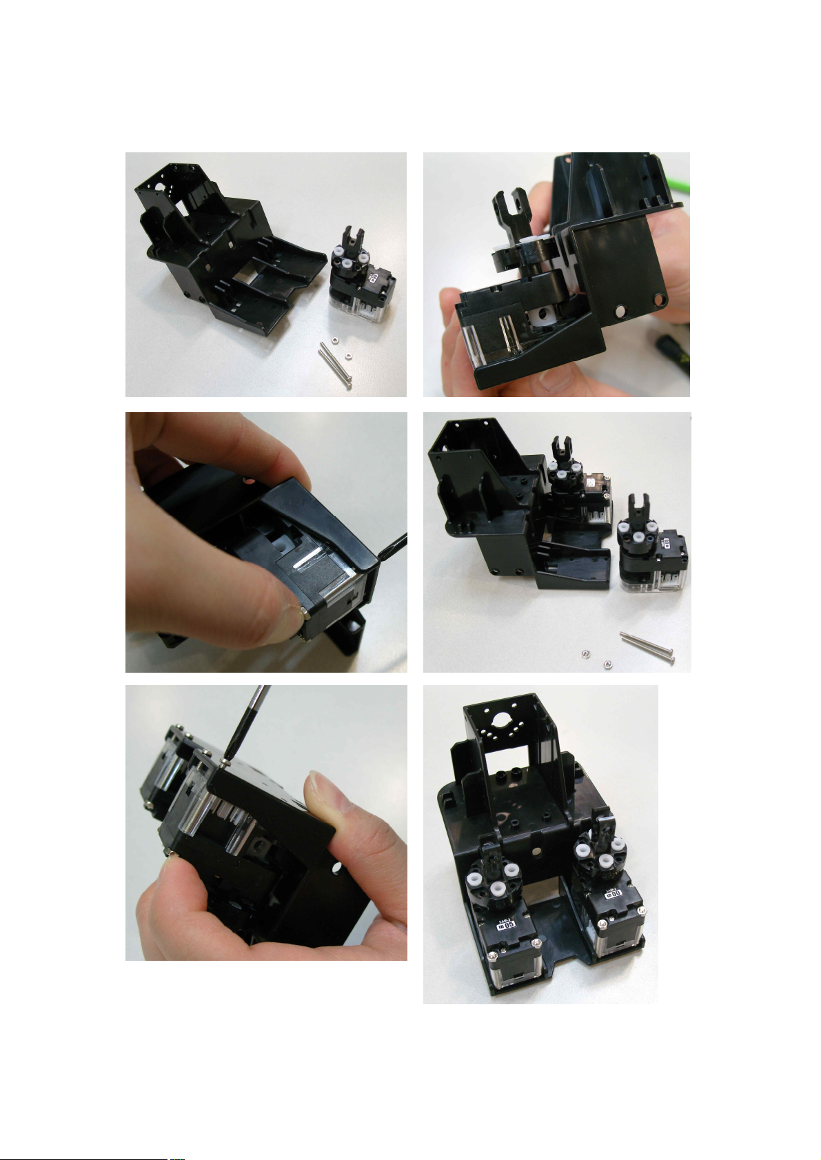
37
STEP4. Connect ID00 and ID05 with Body Frame by using Bolt (B27) and Nut.
Check the ID05 and ID00 connect position well as shown in the below.
Page 38
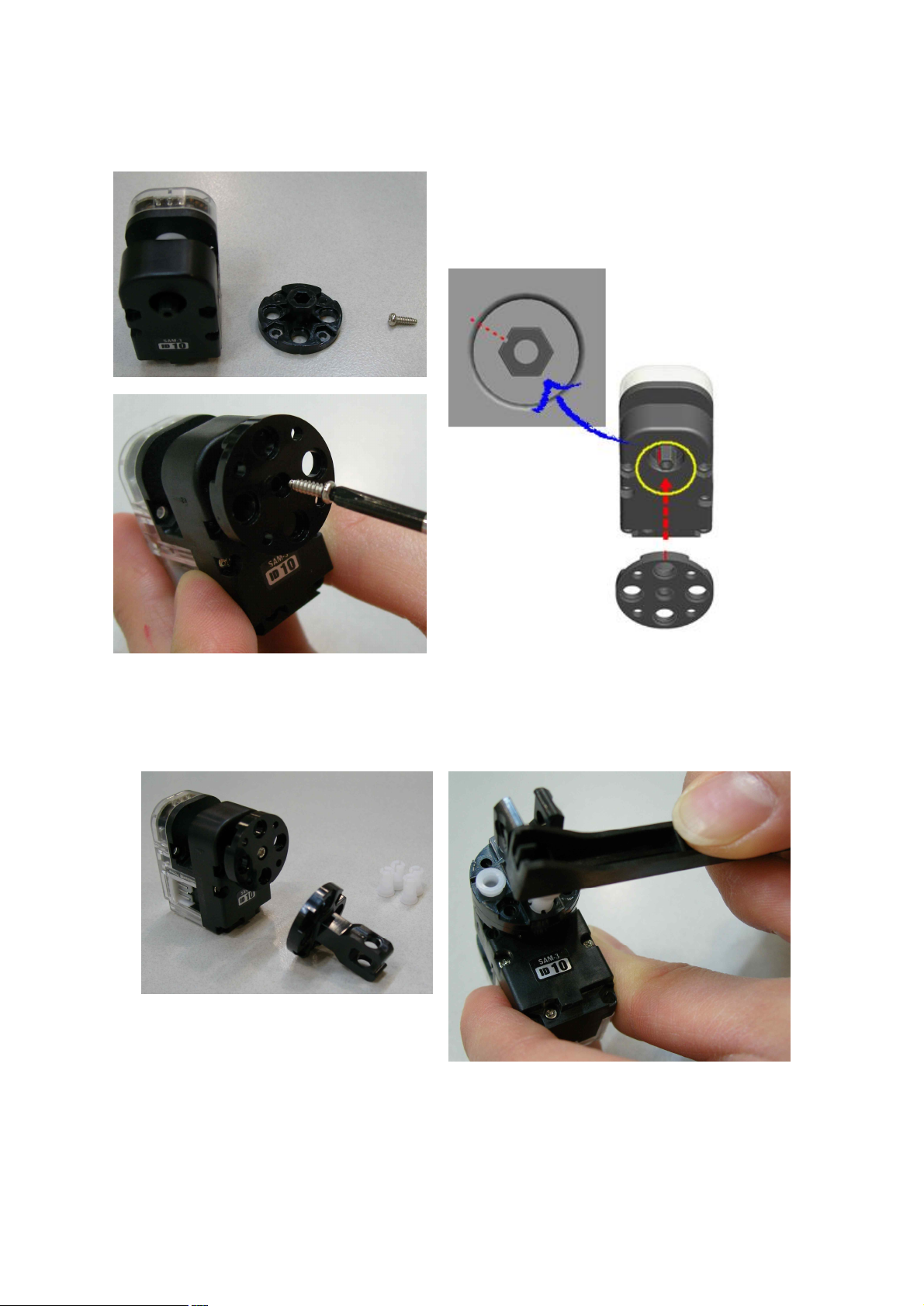
38
STEP5. Connect “Front Horn” with ID10. Check the “Front Horn” and ID00 mark position.
- Smart servo mark position is 11 o’clock while Front Horn mark position is 12 o’clock as shown in the below.
STEP6. Connect “Joint Frame” with “Front Horn” by using “2s rivets” as shown in the below.
Page 39
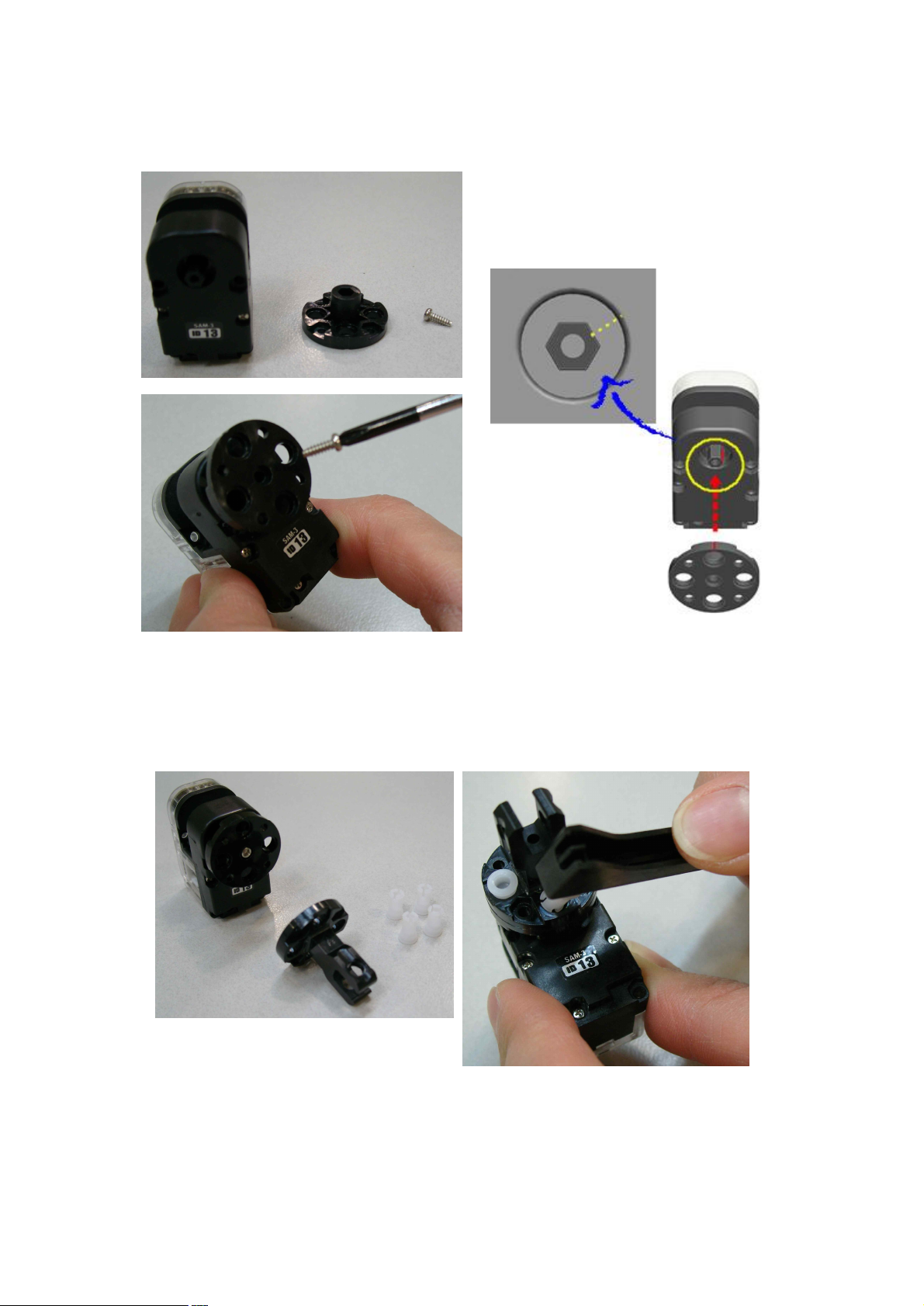
39
STEP7. Connect Front Horn with ID13. Check the Front Horn and ID00 mark position.
- Smart servo mark position is 1 o’clock while Front Horn mark position is 12 o’clock as shown in the below.
STEP8. Connect Joint Frame with Front Horn by using 2s rivets as shown in the below.
Page 40
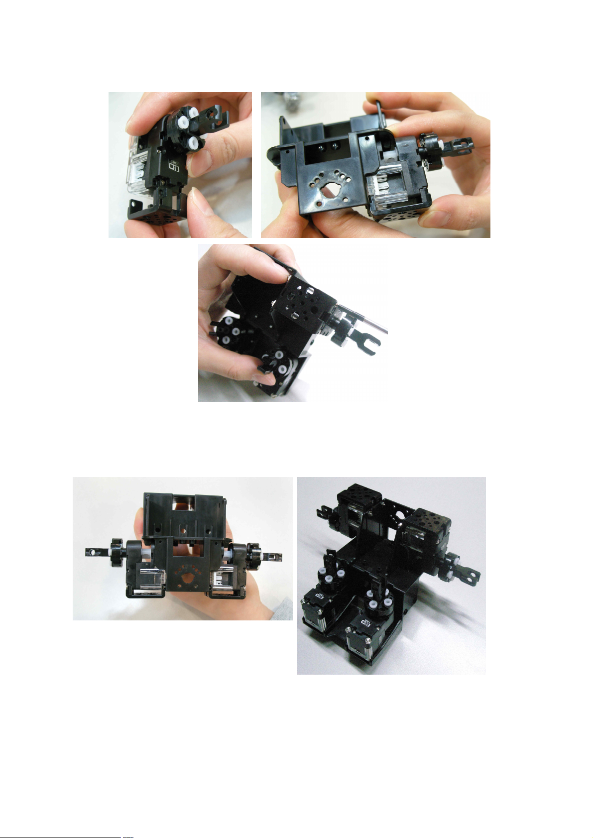
40
STEP9. Connect ‘U’ Frame with ID10 as shown in the below and connect with Body Frame by using Bolt (B30).
STEP10. Connect ‘U’ Frame with ID13 as shown in the above and finish the RQ HUNO shoulder.
Page 41
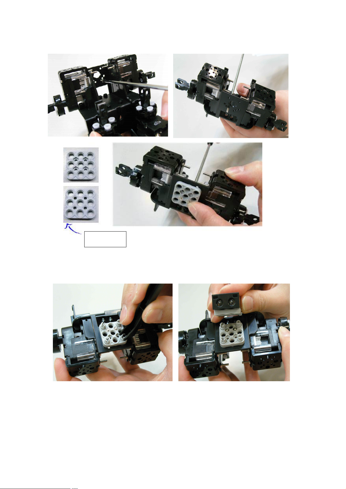
41
STEP11. Assemble Head part. Connect 3*3 frame with Body Frame by using Bolt (B6) and Nut.
3*3 frame
STEP12. Connect IR (Infrared Sensor) into 3*3 frame by using double rivets. .
Page 42
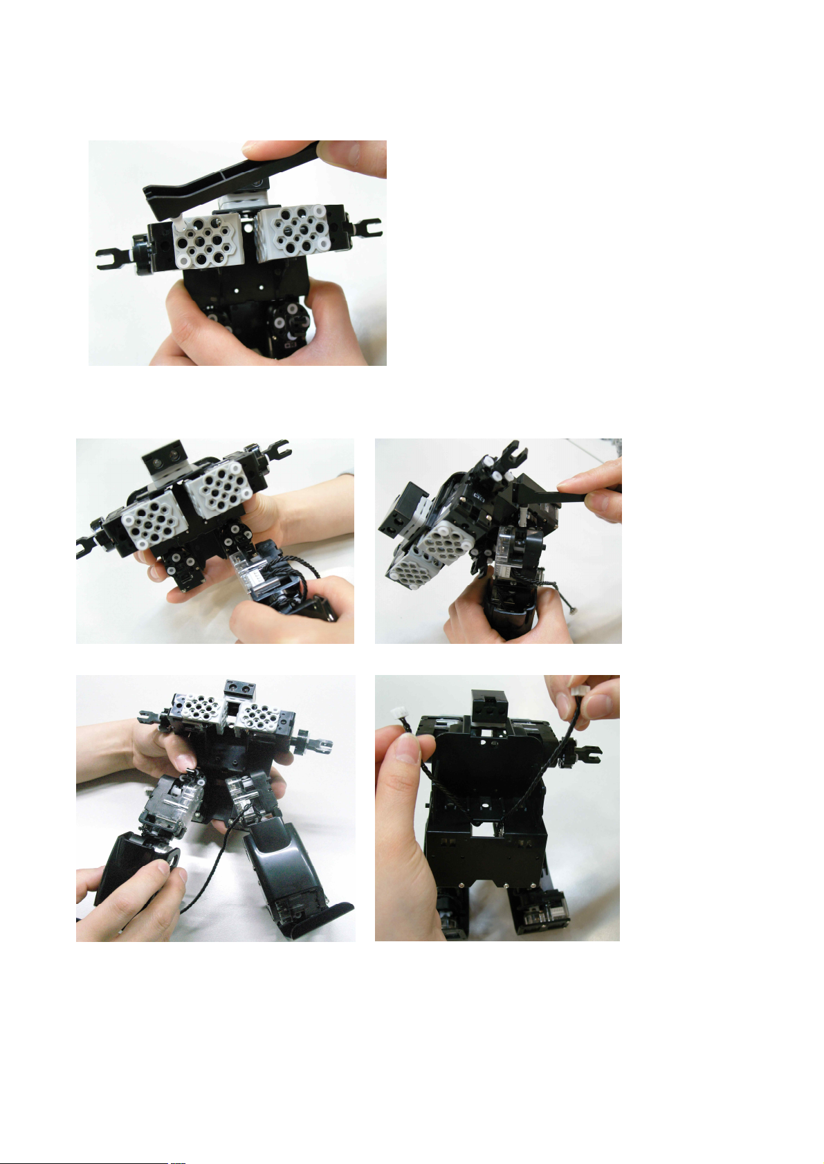
42
STEP13. Connect 3*6 L type frame onto chest part.
STEP14. Connect “ID00 with ID01” and “ID05 with ID06” by using “3s rivet”, respectively . Then, pull the
Cable outside from inside as shown in the below.
Page 43
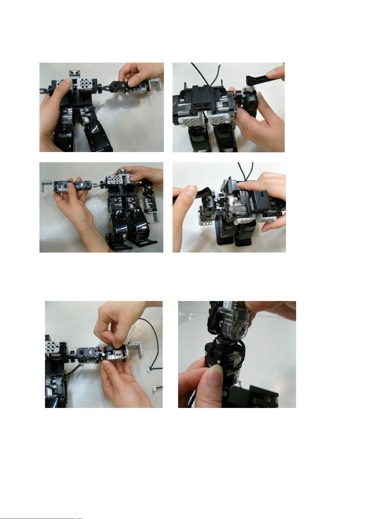
43
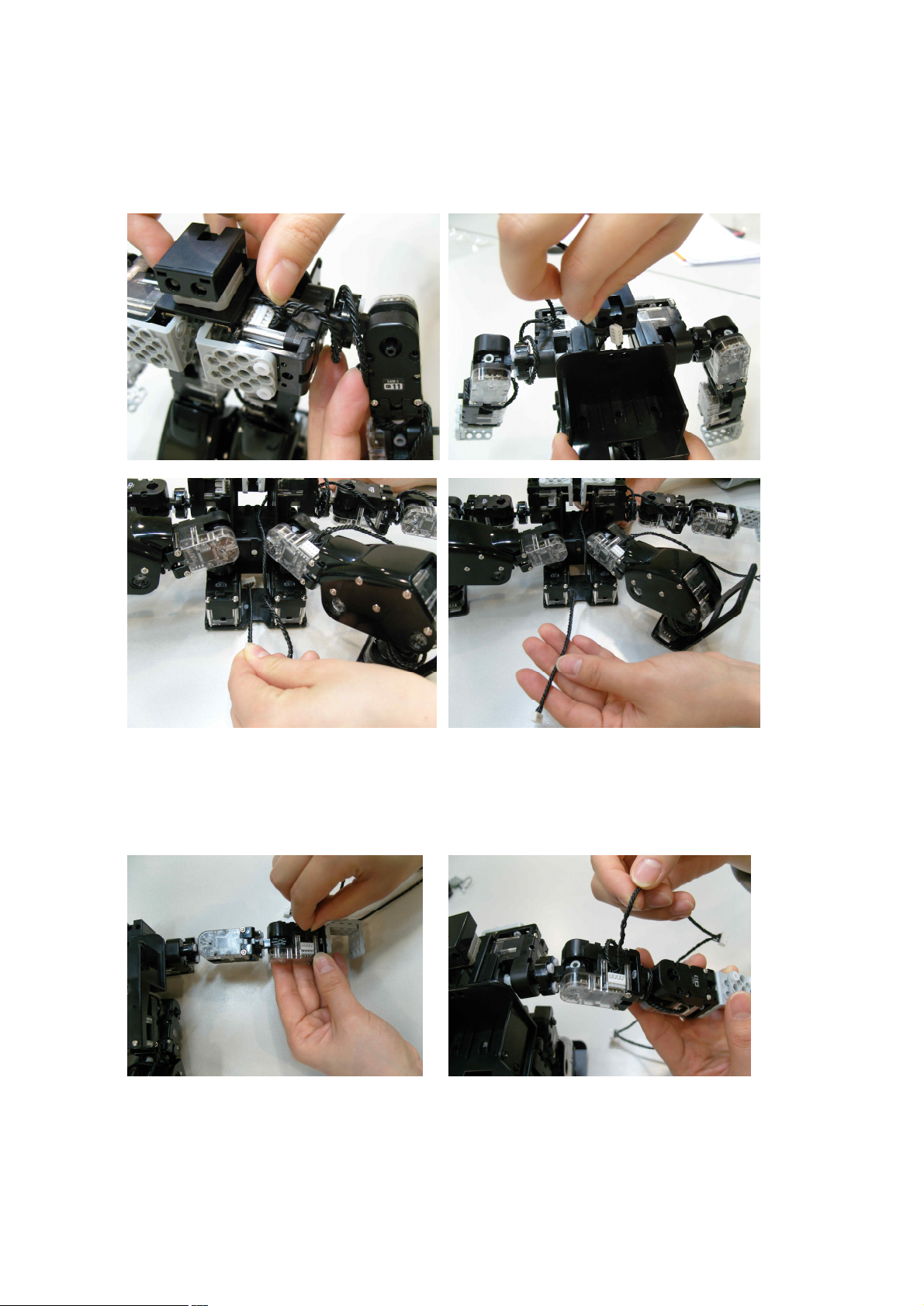
STEP15. Connect “ID10 with ID11”, and “ID13 with ID14” by using “3s rivet”, respectively.
STEP16. Put the first connector of W Cable into ID12, and rotate W Cable 1~2 times then put
the second connector of W Cable into ID 11 as shown in the below.
Page 44
44
STEP17. Then, put the third connector of W Cable into ID 10. Put the fourth connector of W Cable
Inside, then connect with ID00.
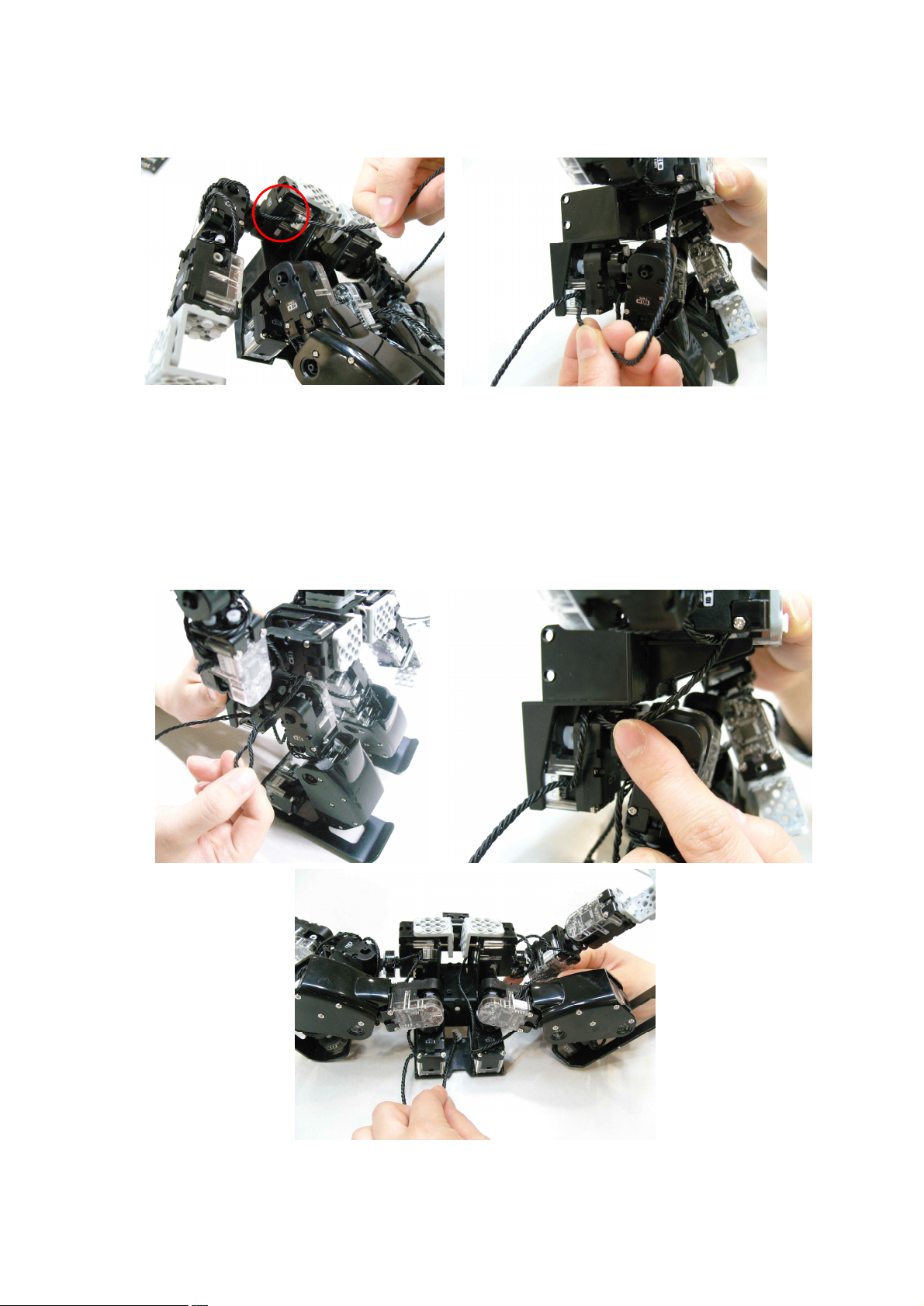
STEP18. Put the first connector of W Cable into ID15, and rotate W Cable 1~2 times then put
the second connector of W Cable into ID 14 as shown in the below.
Page 45
45
STEP19. Put the third connector of W Cable into ID13, and put the fourth connector of W Cable into ID05.
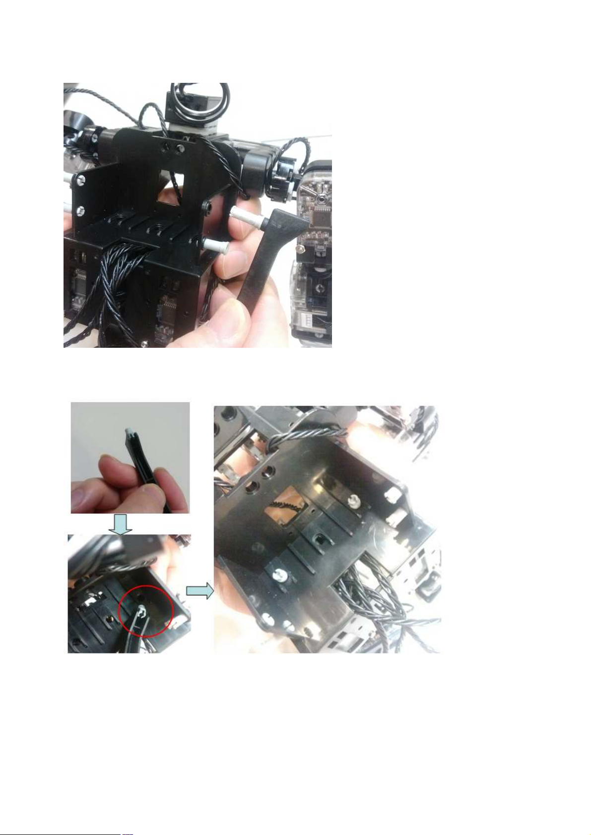
STEP20. Arrange the “W Cabe” as shown in the below, and pull out the “W Cable” from the bottom side of
“Body Frame” to upside.
Page 46
46
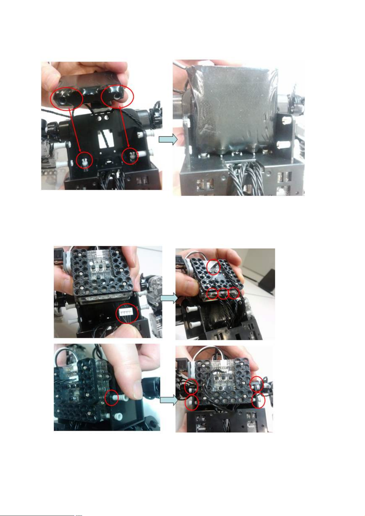
STEP21. Insert four “3s rivets” to “Body frame” to fix Smart Controller as shown in the below.
STEP22. Insert two “double rivets” to “Body frame” to fix “Battery” as shown in the below.
Page 47
47
STEP23. Put “Battery” to “Body Frame” as shown in the below.
STEP24. Connect “W Cable” and fix Smart Controller with “Body Frame” as shown in the below.
Page 48
48
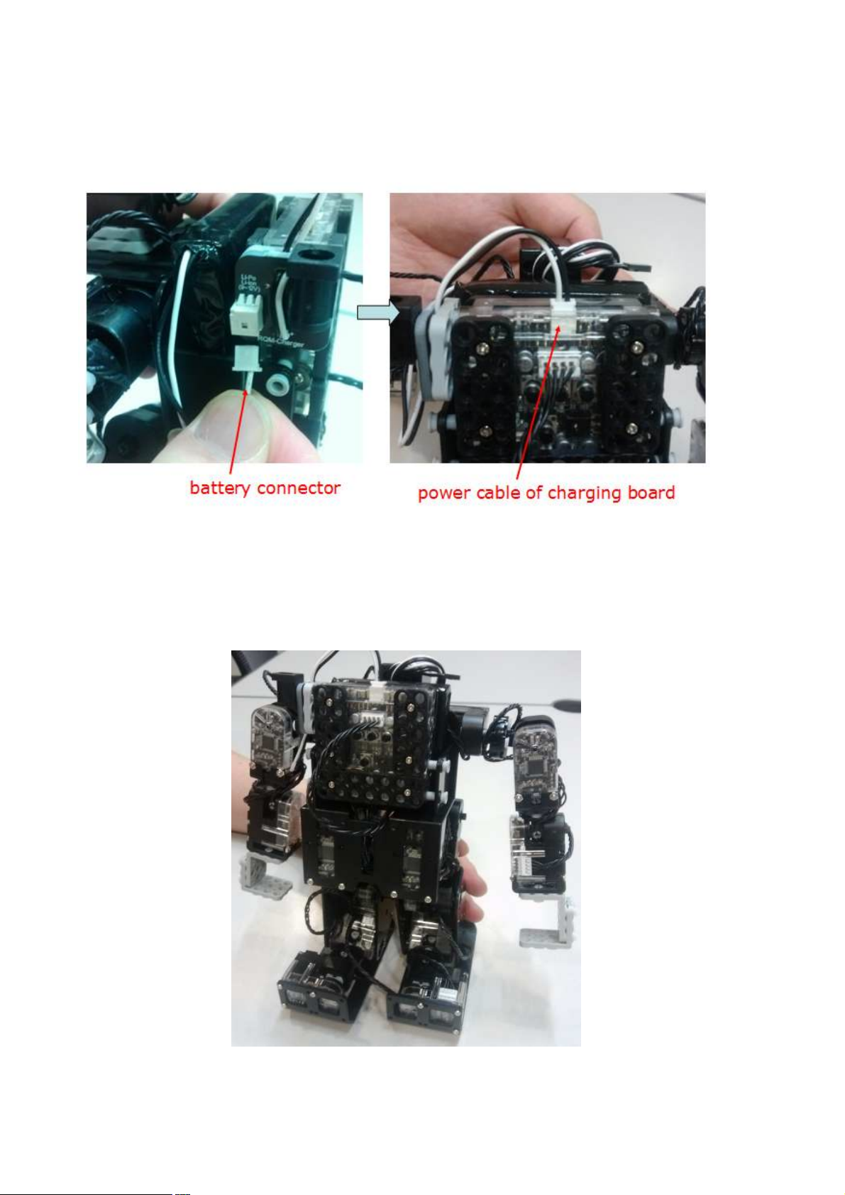
STEP25. Connect battery connector, then also connect “power cable of charing board” to the “Smart
Controller power connector” as shown in the below.
STEP26. Assembly completed.
Page 49
49
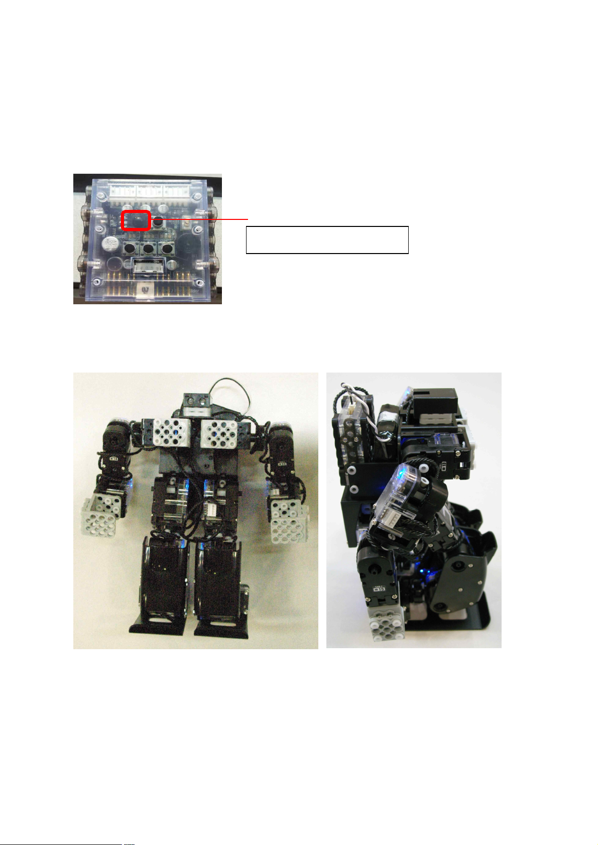
IR remote controller receiver
2.8 Check Assembled Robot
<Basic Posture>
Let’s find out how Robot works after assembly. Firstly, power on (press button ‘P’) in smart controller.
Then, press ‘stop’ button of IR remote controller towards IR remote controller receiver.
Then Robot will take the basic posture as shown in the below.
Page 50
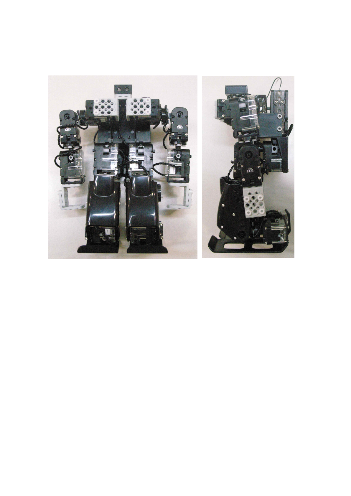
50
<Attention Posture>
Robot will take the “Attention!” posture if you press “button 1” in IR remote controller.
l Please check the assembly guide from the STEP1 again if robot posture is not the same as shown in
the above.
Page 51
51
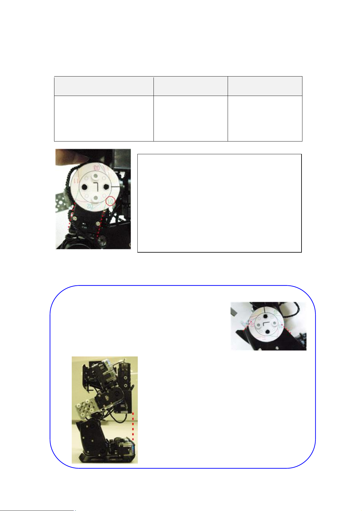
3. Zero Position Adjustment
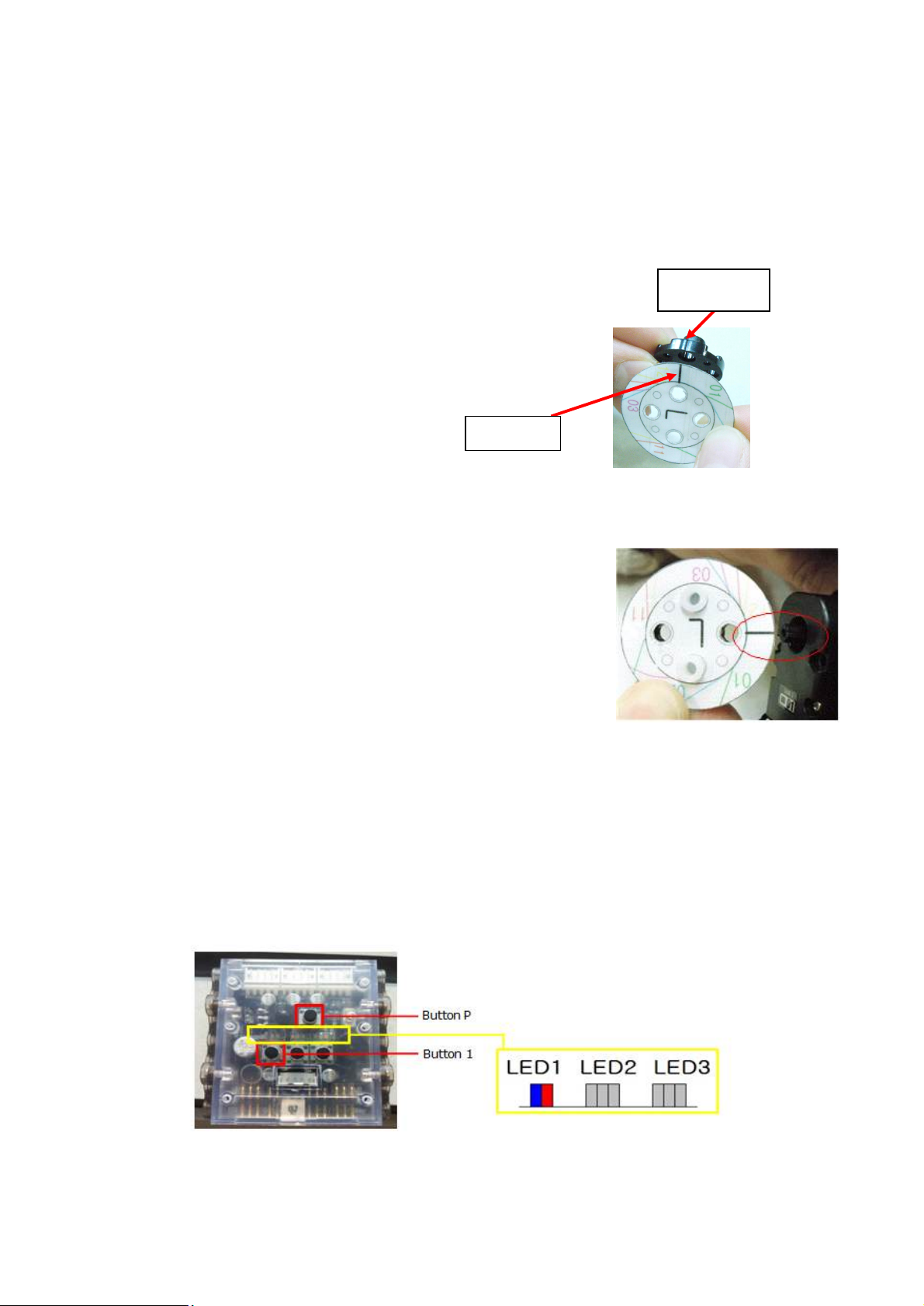
standard line
FrontHorn mark
Zero position is robot standard posture information in order to know the difference of each robot basic posture.
Every robot basic posture would be different a little because every smart servo has own tolerance. For instance,
‘A’ robot motion would play a little bit different in ‘B’ robot because of smart servo tolerance. This difference
can be reduced as you ajdust “zero position adjustment”.
<RQ-HUNO zero position adjustment?
i) Prepare “zero position tool”.
ii) Fix Front Horn with zero position tool by using 2s rivets.
iii) Put FrontHorn into smart servo to be adjusted. Stand line and FrontHorn mark should be matched
as the below.
‘L’ mark zero position tool is to adjust robot “left arm” and “left leg”.
‘R’ mark zero position tool is to adjust robot “right arm” and “right leg”.
iv) Make power-off the smart controller.
v) Press button P while button 1 pressed.
ð LED 1 blue and red LED lights, also, smart servo ID00 blue LED lights.
(Zero position adjustment starts from smart servo ID00.)
Page 52
52
Button 1 Button 2 Button 3
Every time you press button 1,
smart servo is selected in order.
“ID01, ID02, ID03…. ID15,
ID00”.
Smart servo moves
counter clockwise
direction.
Smart servo moves
clockwise direction.
For example, smart servo ID01 blue LED lighs when
ID01 zero position adjustment is started.
ð Make sure that 01 adjustment line is matched
with smart servo ID01.
01 means smart servo ID01.
Adjust smart servo ID01 to fit with 01 number.
vi) Press button 1 for selecting smart servo ID, then press button 2 or button 3 for smart servo
rotating direction.
vii) Press button P to save the “zero position”.
TIP.
=> Each smart servo is to be adjusted to conform
with zero position adjustment line.
But for ID02, ID03, ID07, ID08 is to conform with
Knee Frame, not a smart servo.
=> RQ-HUNO Body Frame should be conform with
the rear side of Foot after zero position.
Page 53
53
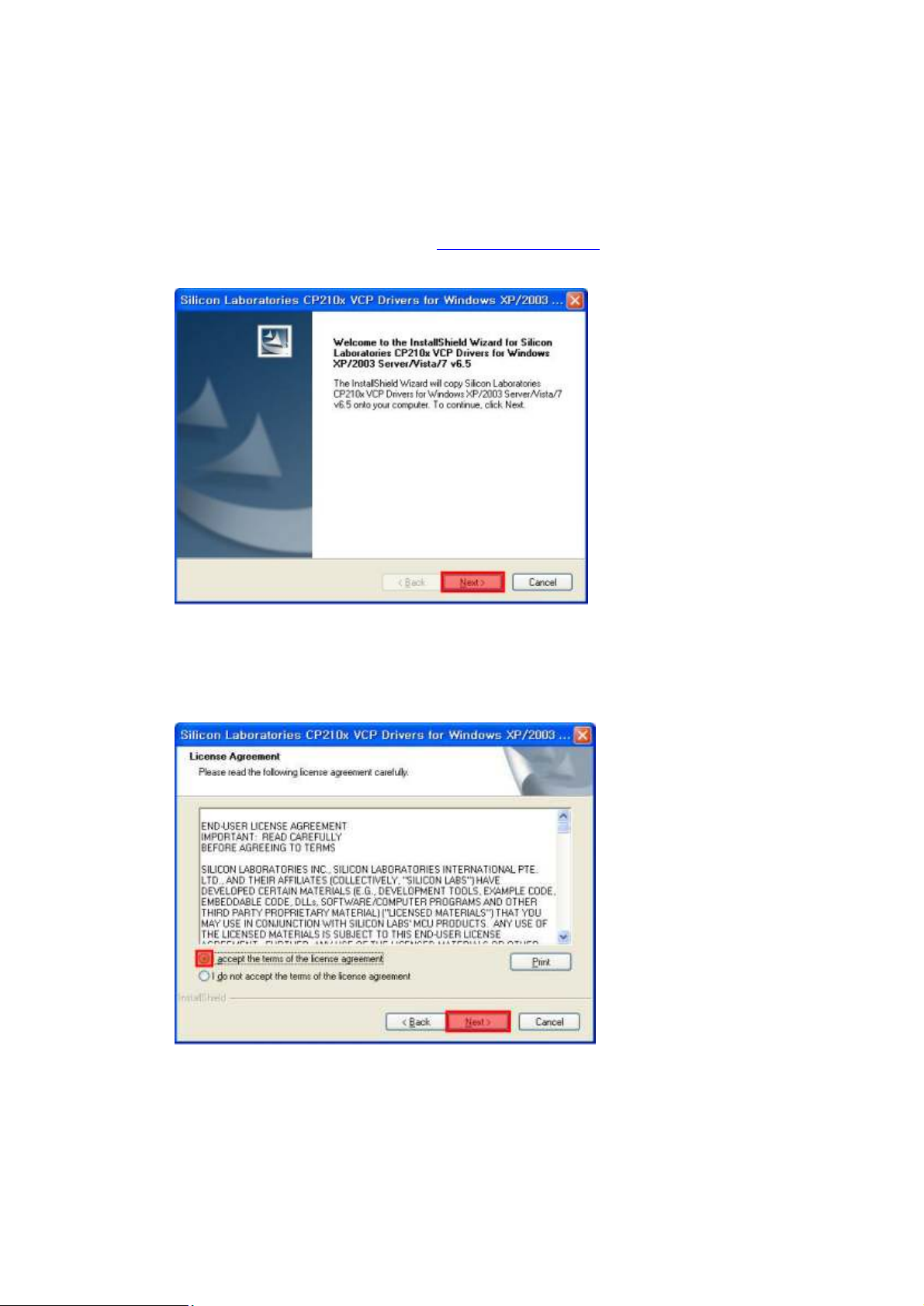
4. Download Cable (UART) driver Installation
You need to install the download cable driver in order to use robot programming software, such as
MotionBuilder, ActionBuilder, Diagnostic Tool and Firmware Upgrade Tool.
1) Download “USB Download Cable Driver” from www.RQWORLD.com and click to start installation.
2) Click “I accept the terms of license agreement”, then click “Next”.
Page 54
54
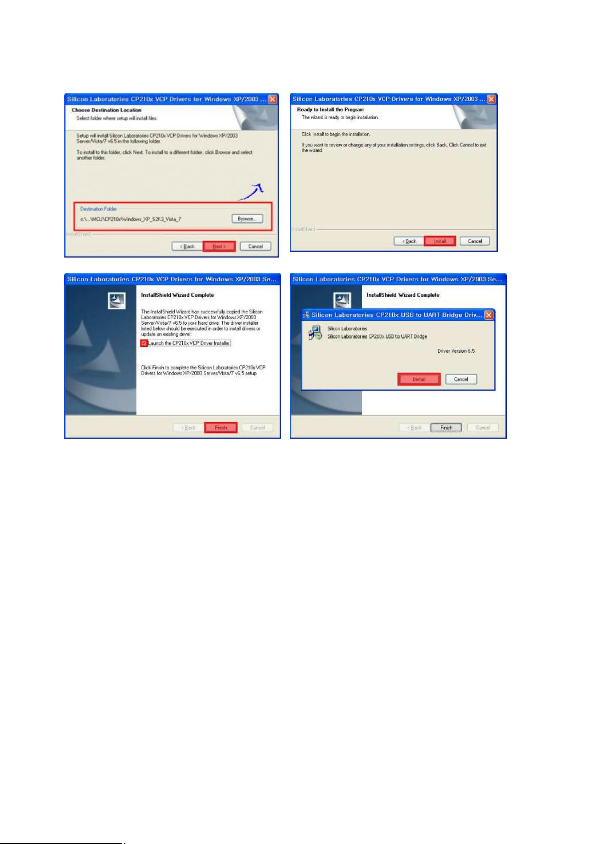
3) Click “Next” and finish the installation as shown in the below..
Page 55
55
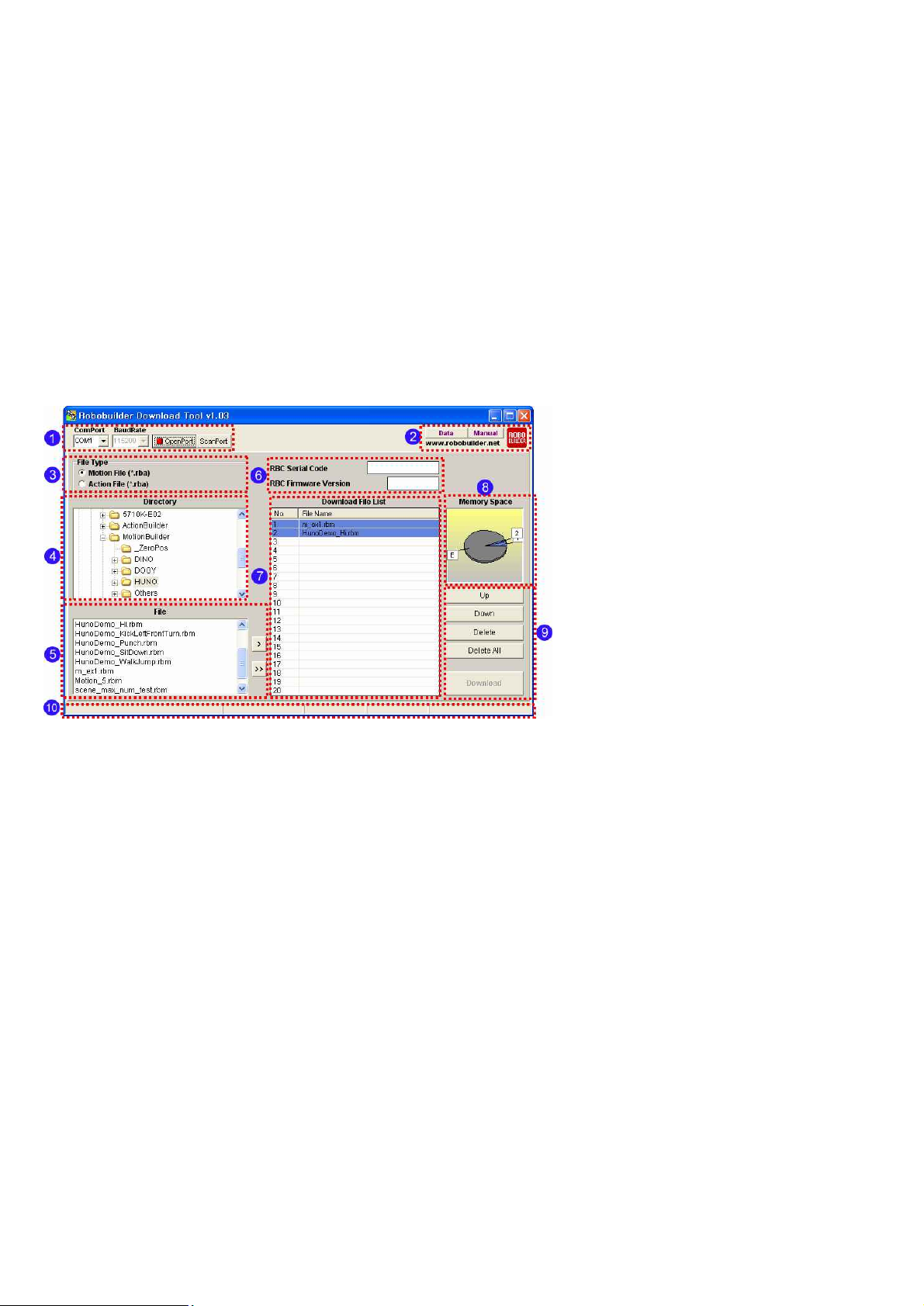
5. Download Tool
5.1 Introduction
Download Tool is used for downloading a number of Motion files (*.rbm) or Action files (*.rba)
at one time. Users can designate the download positions in remote controller.
Layout description
PC Port Connection Part
. COM Port : Designate available COM port for connection of RoboBuilder.
. BaudRate : It shows data transferring speed.
. OpenPort : Open PC COM port in order to connect a RoboBuilder.
. ScanPort : Find available COM port and opens it automatically.
Page 56
56
5.2 Download File
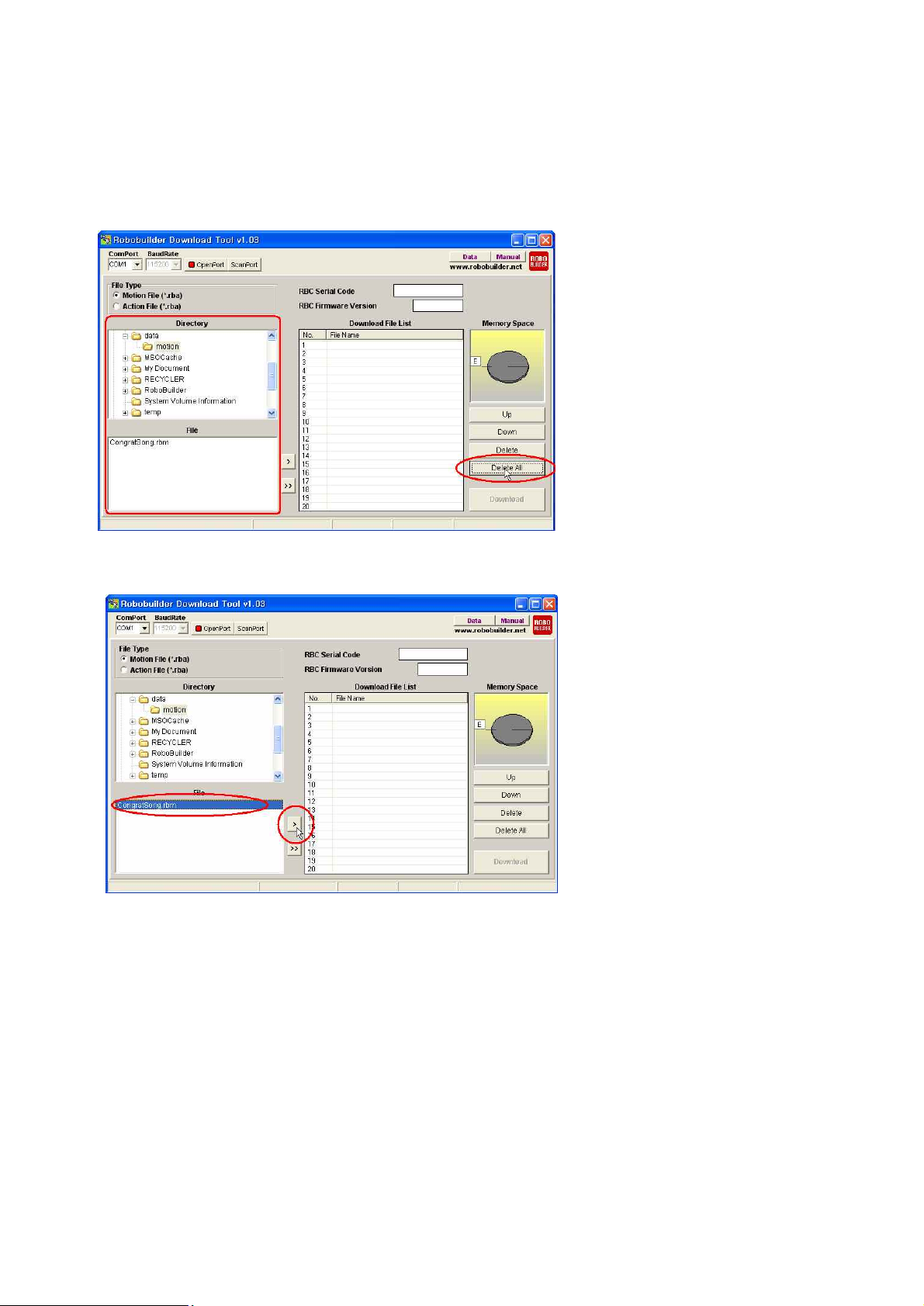
In RoboBuilder Download Tool, it shows the folders and downloaded (made) motion files.
Click “Delete All” in order to delete the previous downloaded files in the list.
In order to insert into Download File List section, select the file then, click ‘>’ button.
※ Users can use Drag & Drop function.
Page 57
57
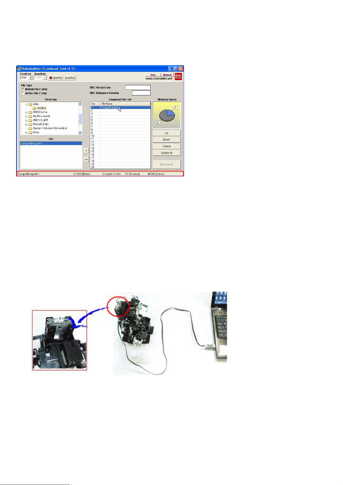
If you click a file in the Download File List, it shows file name, file size, robot platform, scene number,
performance time.
※ If registered files are more than one in the ‘Download File List’, users can change
the downloading sequence by clicking “Up” or “Down” button.
※ Users can do this function by using Keyboard.
‘Up’ button = ‘+’ Key
‘Down’ button = ‘-‘ Key
‘Delete’ button = ‘Delete’ Key
Connect RQ-HUNO and Download (UART) Cable as shown in the below.
Page 58
58
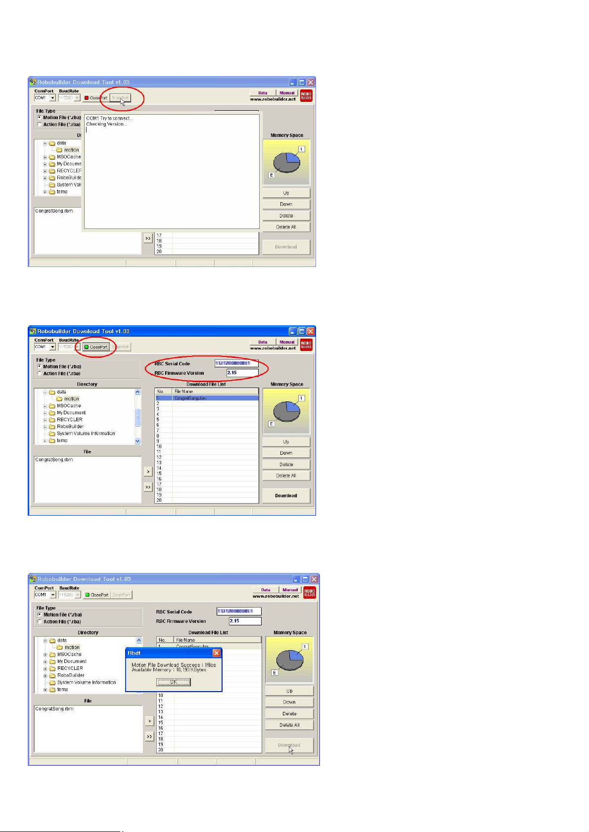
Click ‘ScanPort’ button in order to find available COM Port.
RBC serial code and Firmware Version will be shown if connected properly.
And “ClosePort” button will be shown as well.
Click ‘Download” button, in order to all files in the “Download File List”.
Then it starts downloading into RBC Box. Following message box will shown after downloaded completely.
Page 59
59
6. MotionBuilder
6.1 Introduction
This document explains how to use MotionBuilder the motion building tool for RQ-HUNO.
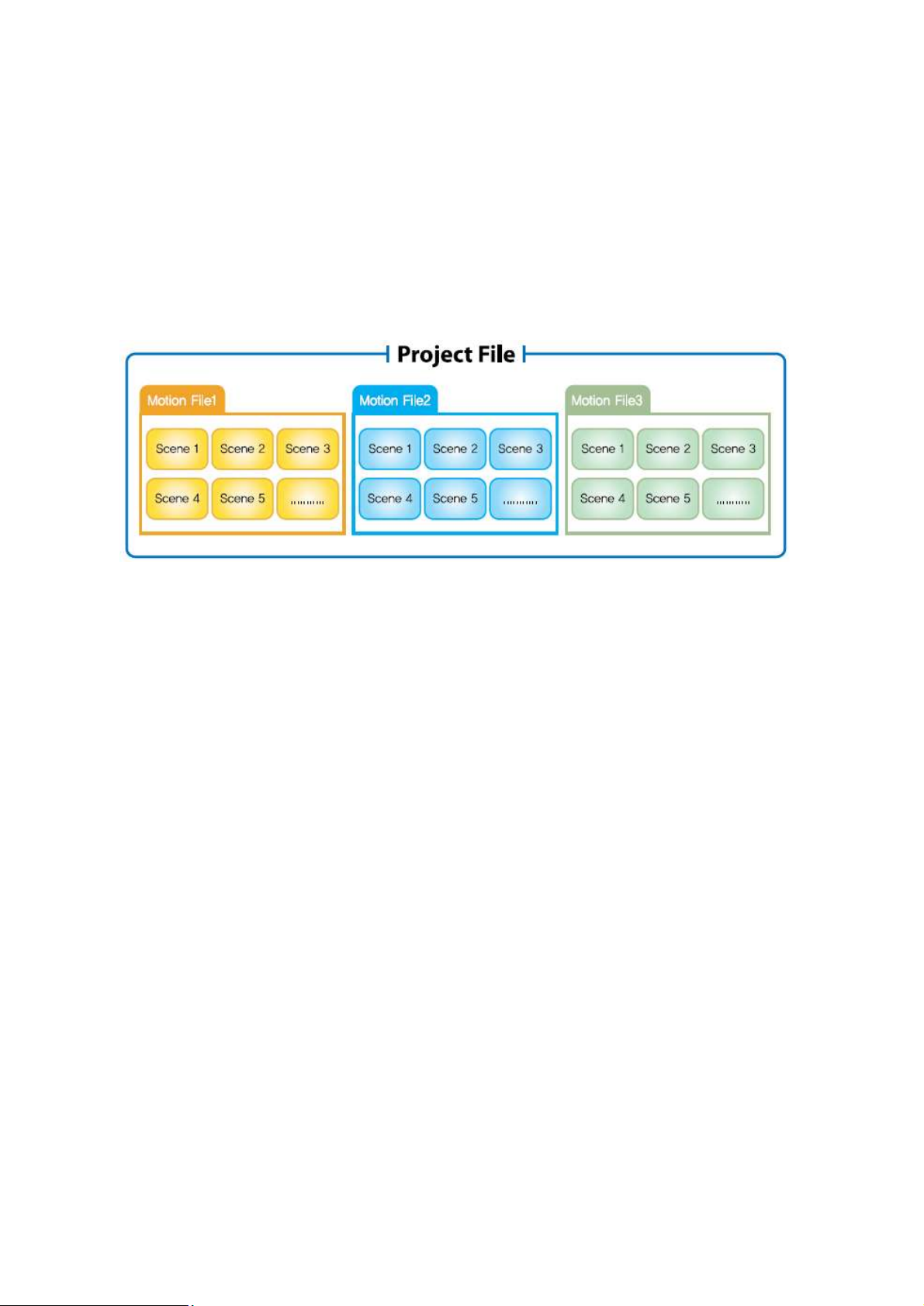
What are project file, motion file, scene, frame, transition time?
Project file(*.prj)
: A project file contains the information such as the robot’s type and more. It is used to
manage multiple motion files of a robot efficiently. Therefore, one project file includes one or
more motion files.
Motion file(*.rbm)
: A motion file contains the complete data to execute its movement. One motion file consists
of multiple scenes.
Scene
: A scene is a smaller motion unit that constitutes a complete motion file. A scene consists
of start position and destination position. Except the first scene, the start position of a scene
is the destination position of its previous scene. When a scene is executed, the frame
data is generated automatically according to the predefiend number of frames and delivered
to each actuator modules.
Frame
: A frame is the smallest motion unit that constitutes a scene. Each frame can be considered
as the still image that is actually sent to robot actuators. The more frames you define,
the smoother the motion becomes. One scene can have from 1 up to 100 frames.
Transition Time
: Transition time is the time duration that is taken to execute a scene. Transition time is
closely related with the number of frames. It can have value from 20msec up to 6000msec.
The minimum transition time that can be allocated for a frame is 20msec.
e.g) If scene A has 10 frames, the transition time can be selected from 200 up to 60000.
Page 60
60
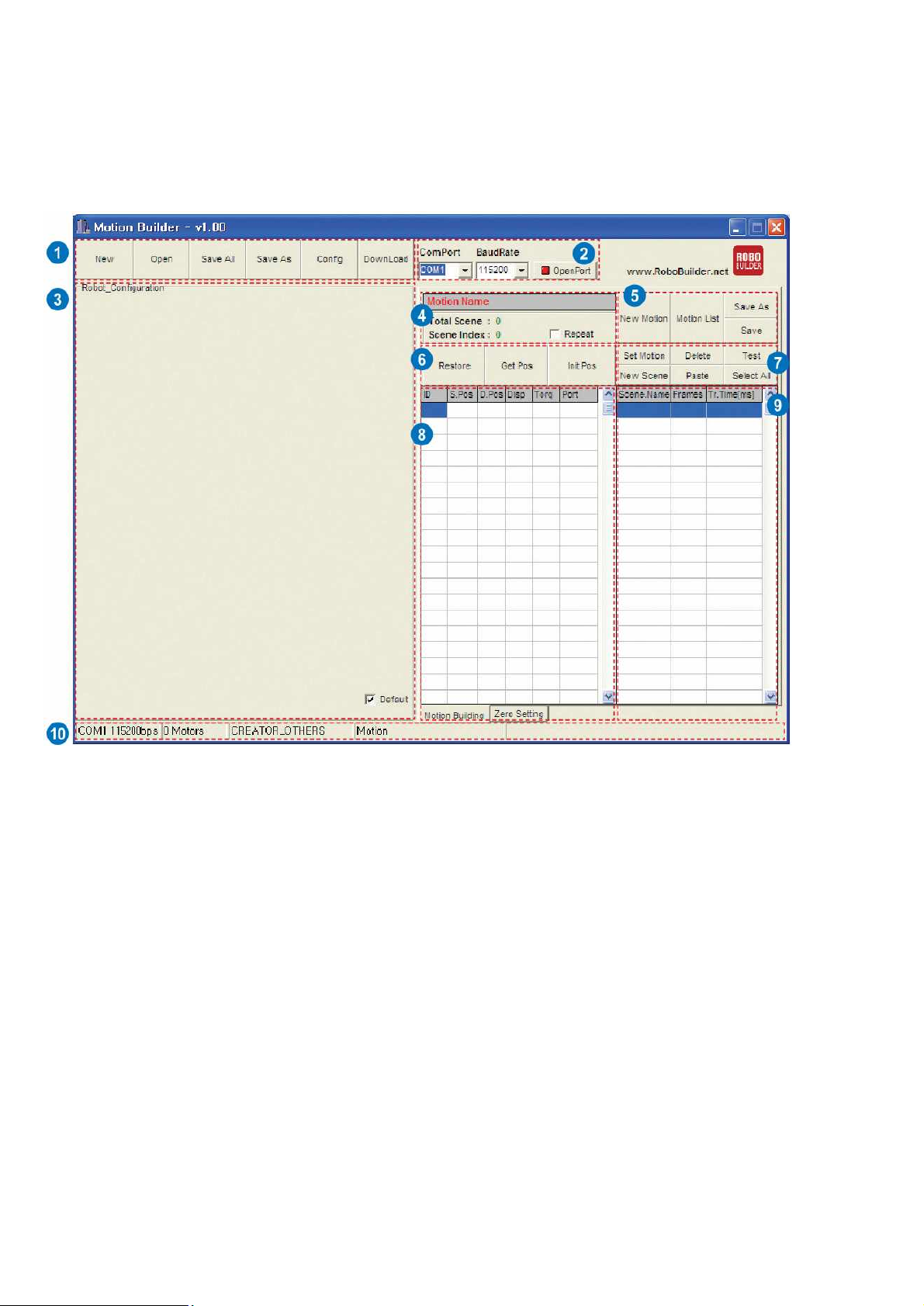
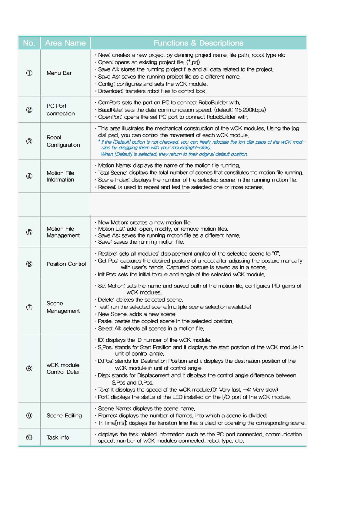
Screen Layout
This is the screen layout of the MotionBuilder.
Page 61
61
Page 62
62
6.2 Motion Programming #1
Let’s try one simple motion programming for RQ-HUNO.
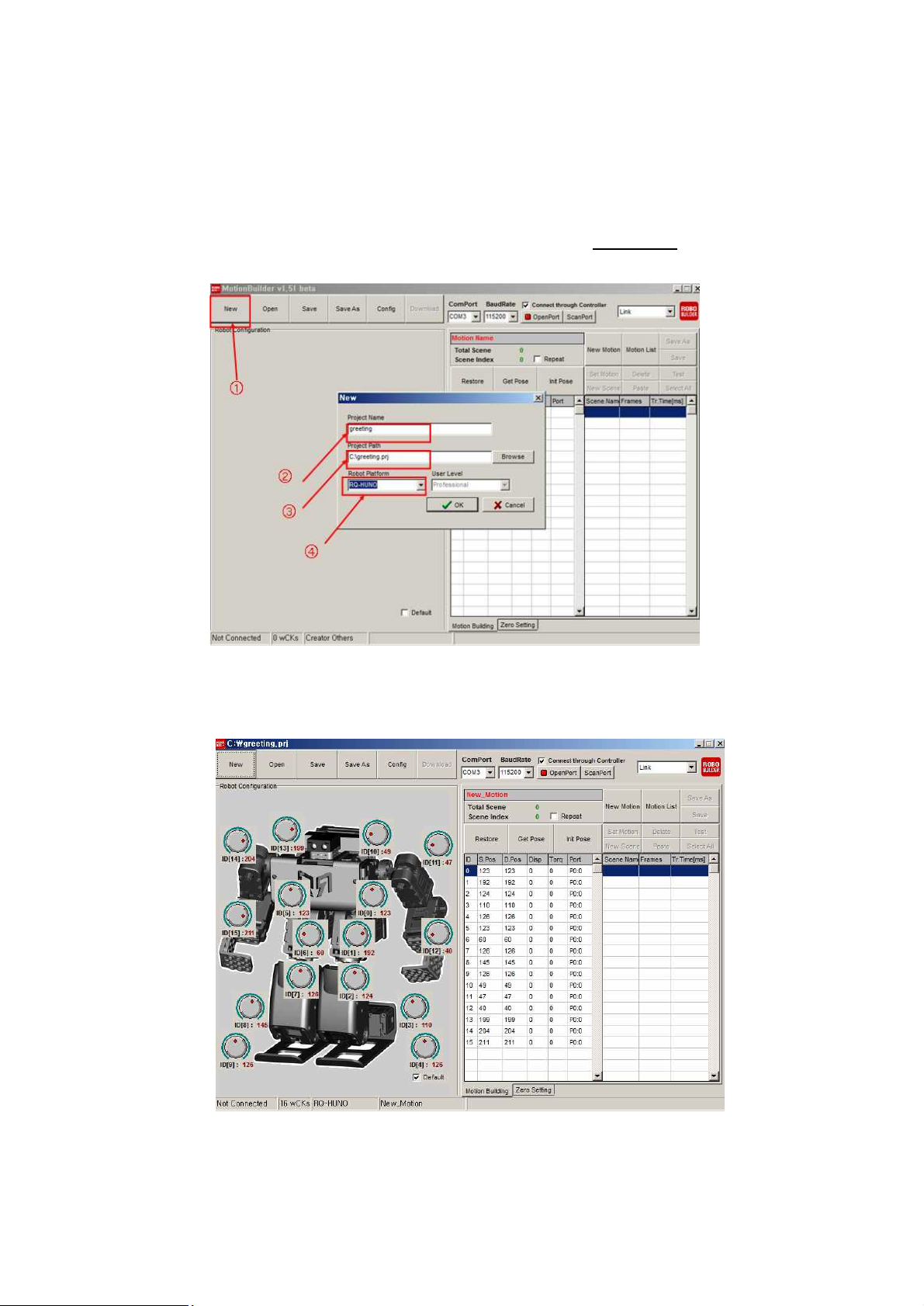
1) Run “MotionBuilder” and click “New”.
Input “greeting” in Project Name, then select Robot Platform “RQ-HUNO”.
2) Click “OK”, then it shows as below.
Page 63
63
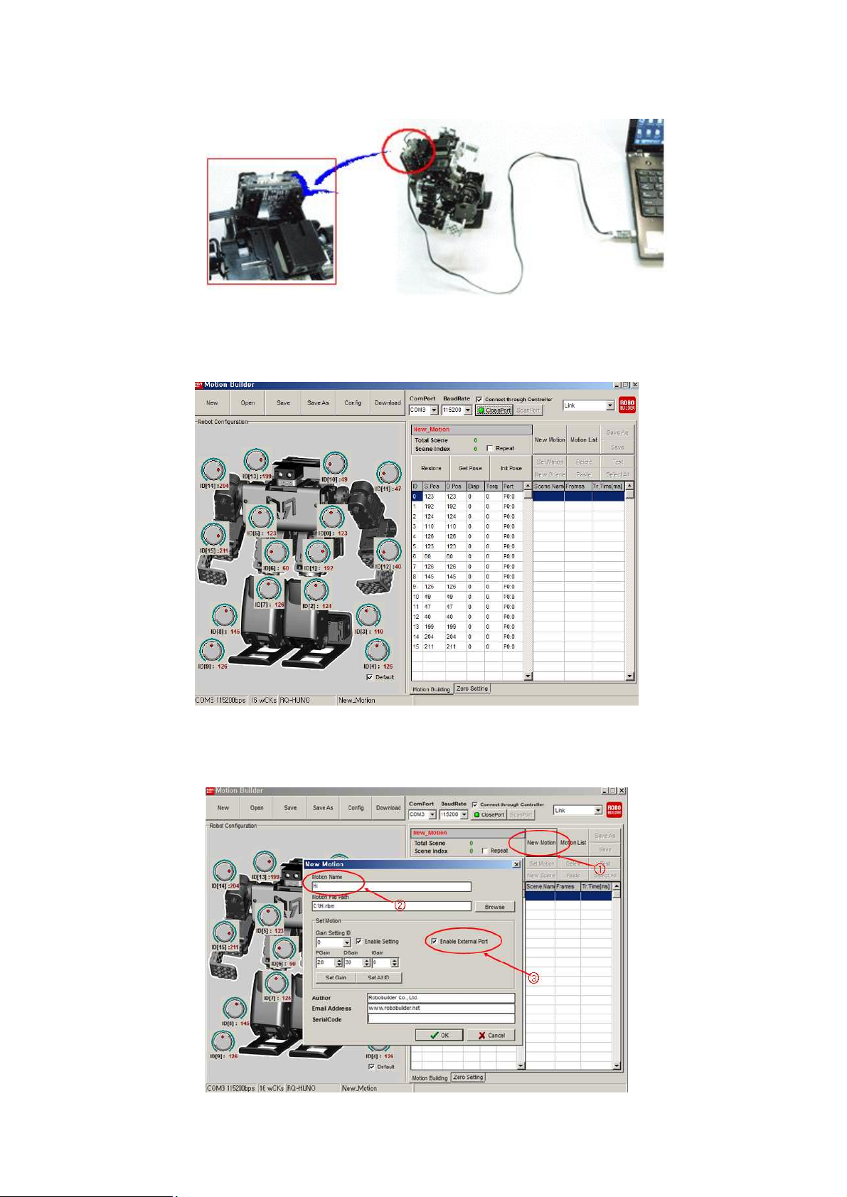
3) Connect RQ-HUNO with PC by using “Down Cable (UART)” then, power on smart controller
(Button P)
4) Click “Scan Port” to search correct COM Port, or you can click “Open Port” if you know the COM
Port No.
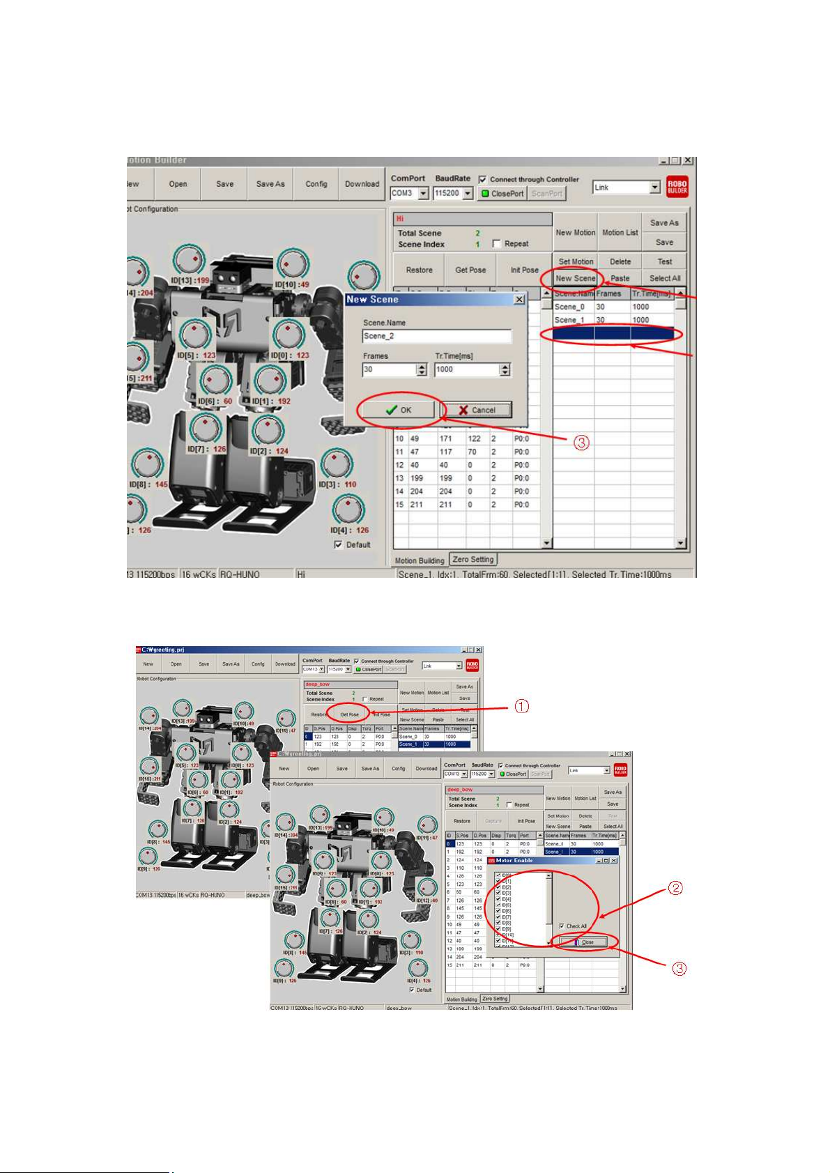
5) Click “New Motion”. Then input “hi” in Motion Name.
If you want to use smart servo LED, check the “Enable External Port”, then, click “OK”.
Page 64
64
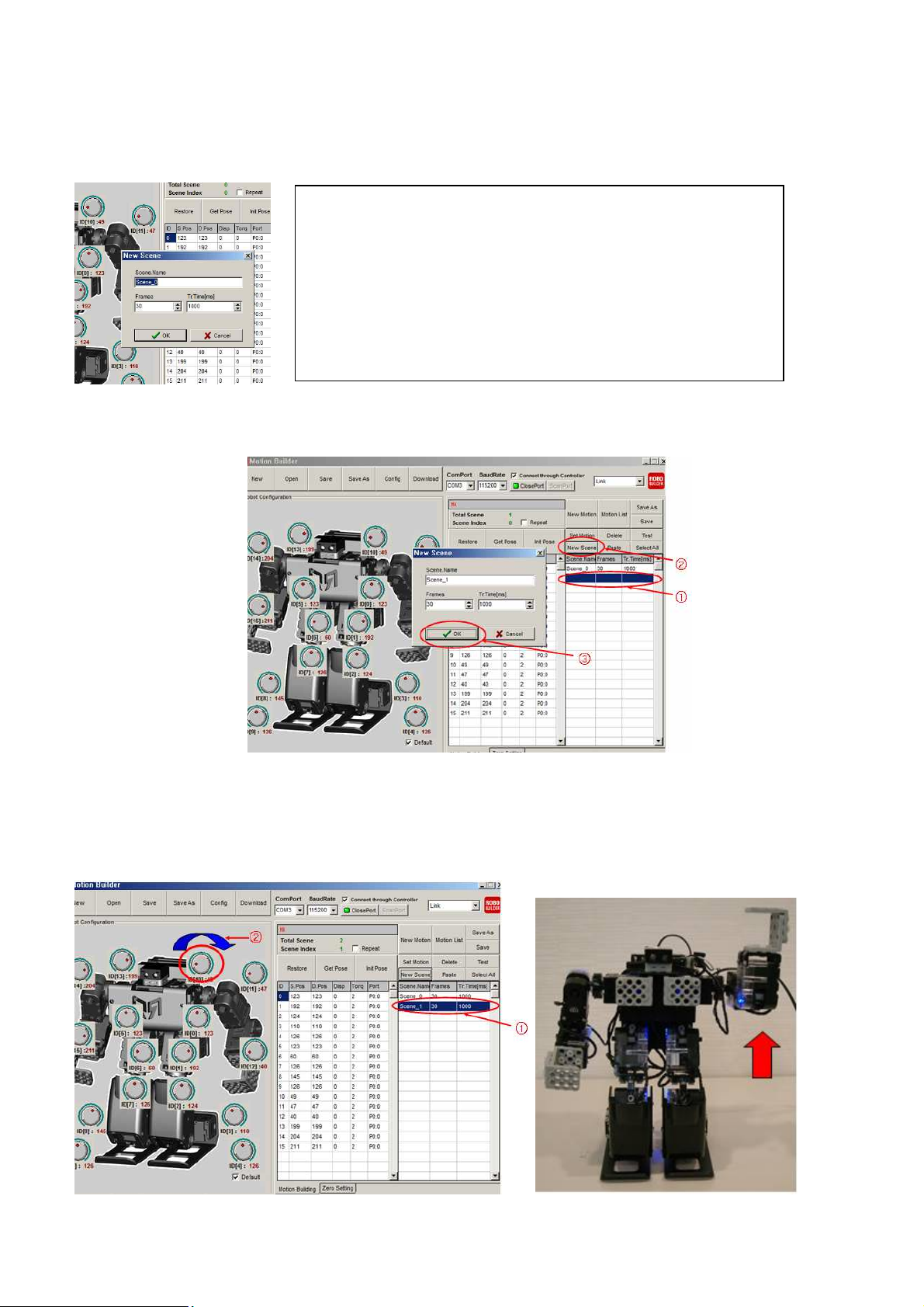
- Frames : If you increase the Frames, robot moves smoothly.
-Motion Run Time : Each frame run time range is 20~1000msec.
TIP. It is recommended that first scene and last scene is for robot basic
posture for stable motion movement
Therefore, do not revise the Frames and Run Time value of Scene0
6) If you see the New Scene window, click “OK”.
You can adjust “Frames”, and “Motion Run Time (ms)”.
7) In order to move up and shake the arm, add the second scene. For adding new scene, you
should select next empty scene before click “New Scene”.
8) In order to move up and shake the arm, add the second scene. For adding new scene, you
should select next empty scene before click “New Scene”. Move the Jog Dial of “ID10”.
Page 65
65
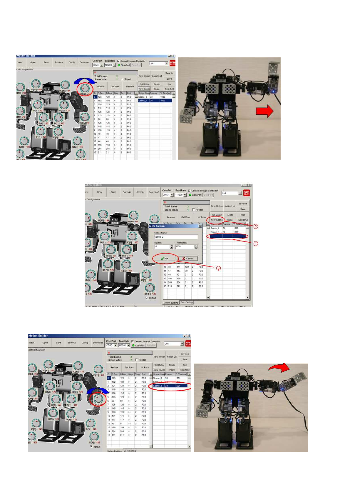
9) Move the Jog Dial of “ID11”.
10) For the next movement, add the third scene.
11) Move the Jog Dial of ID12.
Page 66
66
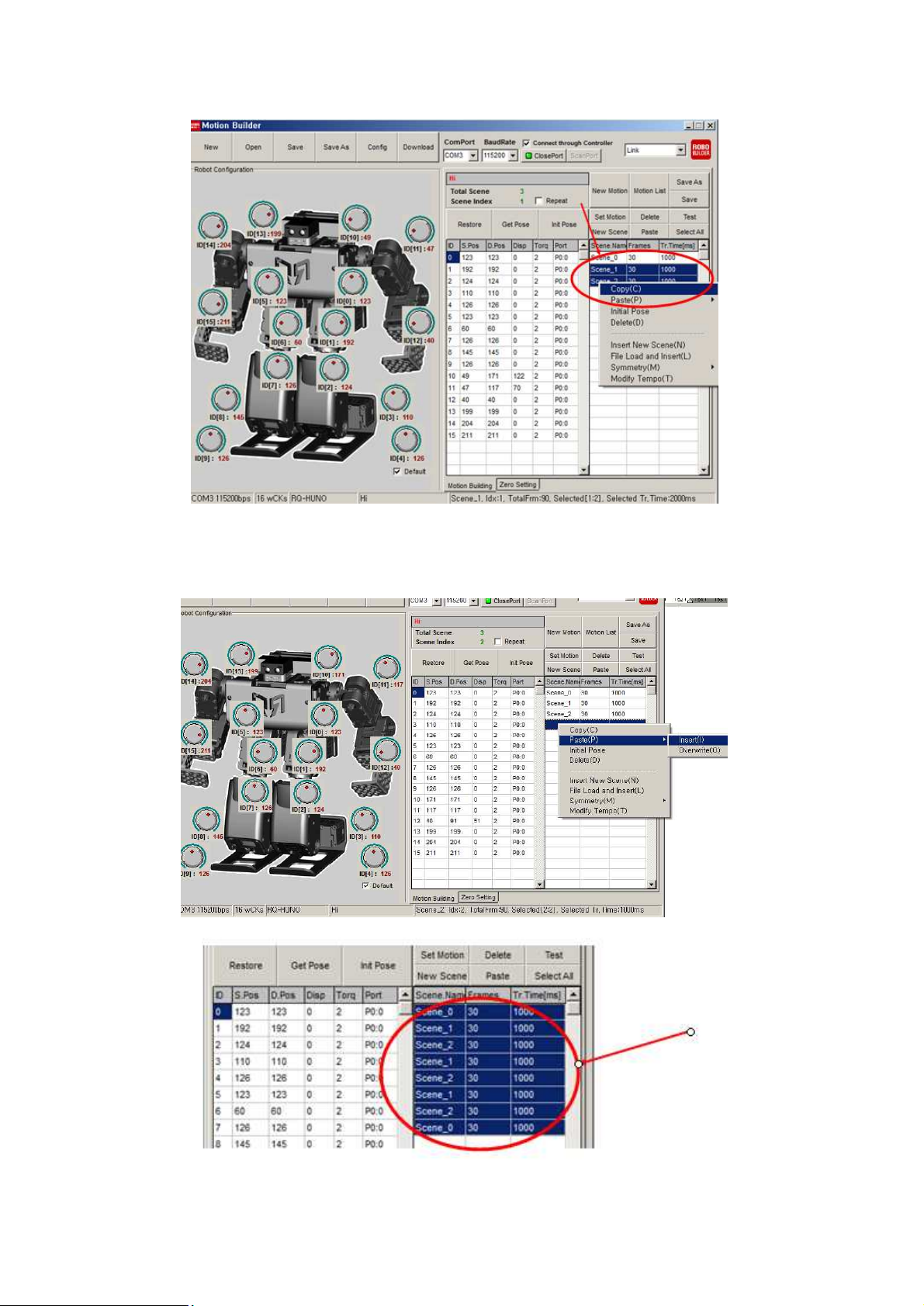
12) Then, let’s make the arm shaking motion like “saying Hi”. Copy the Scene 1 and Scene 2.
13) Paste the Scene 1 and Scene 2 to the next empty scene space, and do the paste again.
Lastly, copy the “Scene 0” and paste to the last scene.
Page 67
67
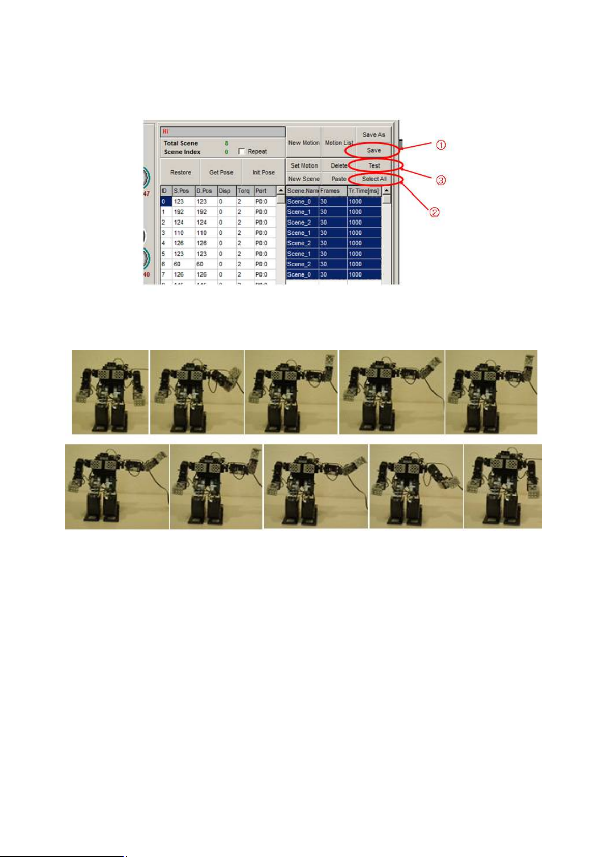
14) Save the Motion file, Click “select All” and then click “Test” button.
15) Completed “Hi.rbm” motion movement is as follows.
.
Page 68
68
6.3 Change Motion Speed
Let’s find out about frame and motion run time.
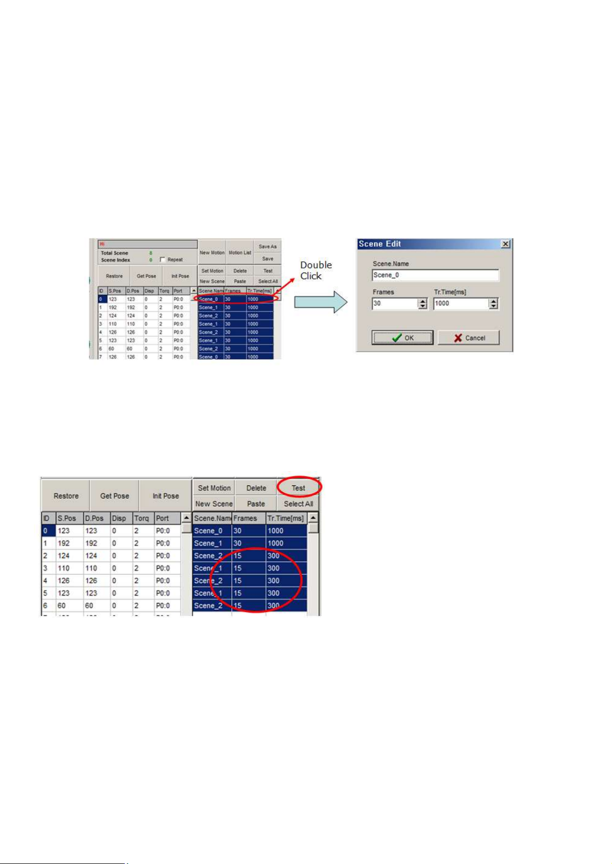
We have applied basic frame and motion run time (30 frames, 1000 msec) in the previous motion
1) If you look at the scene part, you can see all the frame value is 30 and time value is 1000. you can
change the frames and time as you double-click related scene.
2) Minimum motion run time is 20msec for each frame. Therefore, time value should be at least 600
msec if frames are 30. Change the frame value first, then input proper time value.
3) Try to change the frame value to 15, and time value is 300msec then click “Test” as shown below.
4) You can see that motion speed is faster than before.
Page 69
69
6.4 Motion Programming #2
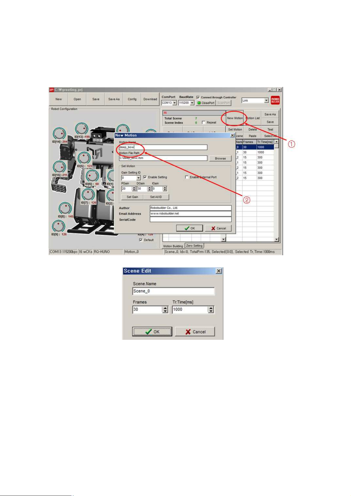
In this section, we will make a deep bow HUNO motion.
1) Click “New Motion”, then input motion name as a “deep_bow”.
Page 70
70
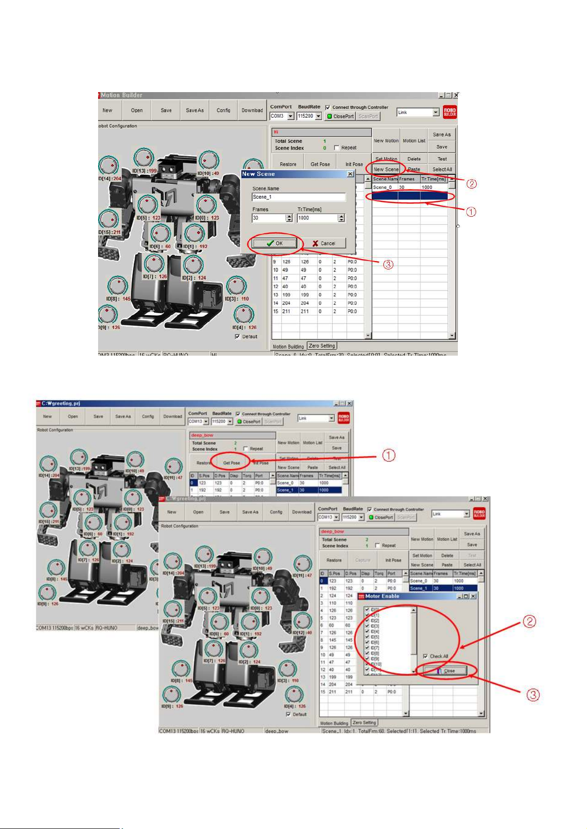
2) Click “New Scene” to add new scene.
3) Click “Get Pose”, you can see “Motor Enable” window, then check “Check All”.
Page 71
71
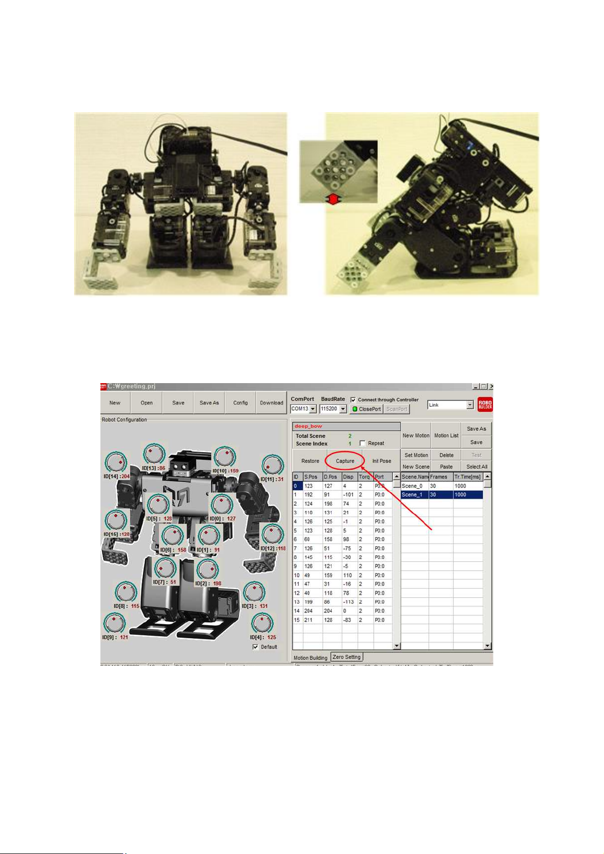
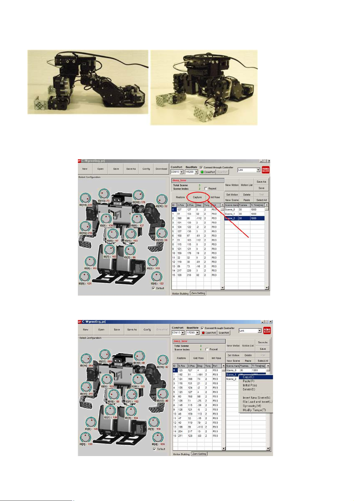
4) Then, you can make the RQ-HUNO posture by using your hand (Not by Jog Dial) as shown in the
below.
5) Then, click “Capture” to complete the above scene.
Page 72
72
6) Click “New Scene” to add new scene.
7) Click “Get Pose”, you can see “Motor Enable” window, then check “Check All”.
Page 73
73
8) Then, you can make the RQ-HUNO posture by using your hand (Not by Jog Dial) as shown in the
below.
9) Then, click “Capture” to complete the above scene.
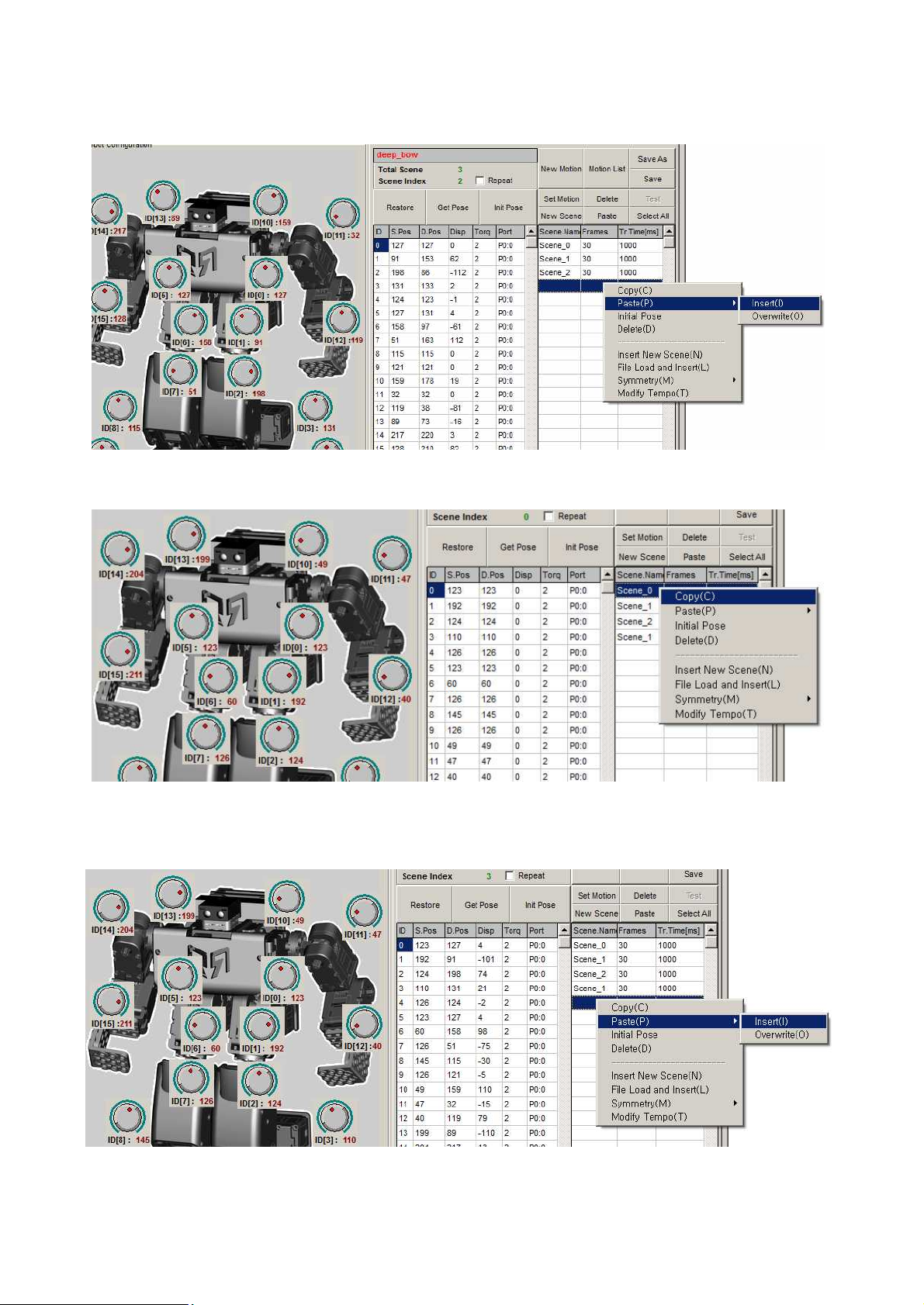
10) Now, Copy the “Scene_1” to ready get up.
Page 74
74
11) Mouse right click, then paste-insert to the next empty scene space after Scene_2.
12) Copy the “Scene_0” to take a basic posture.
13) Mouse right click, then paste-insert to the next empty scene space after Scene_1
Page 75
75
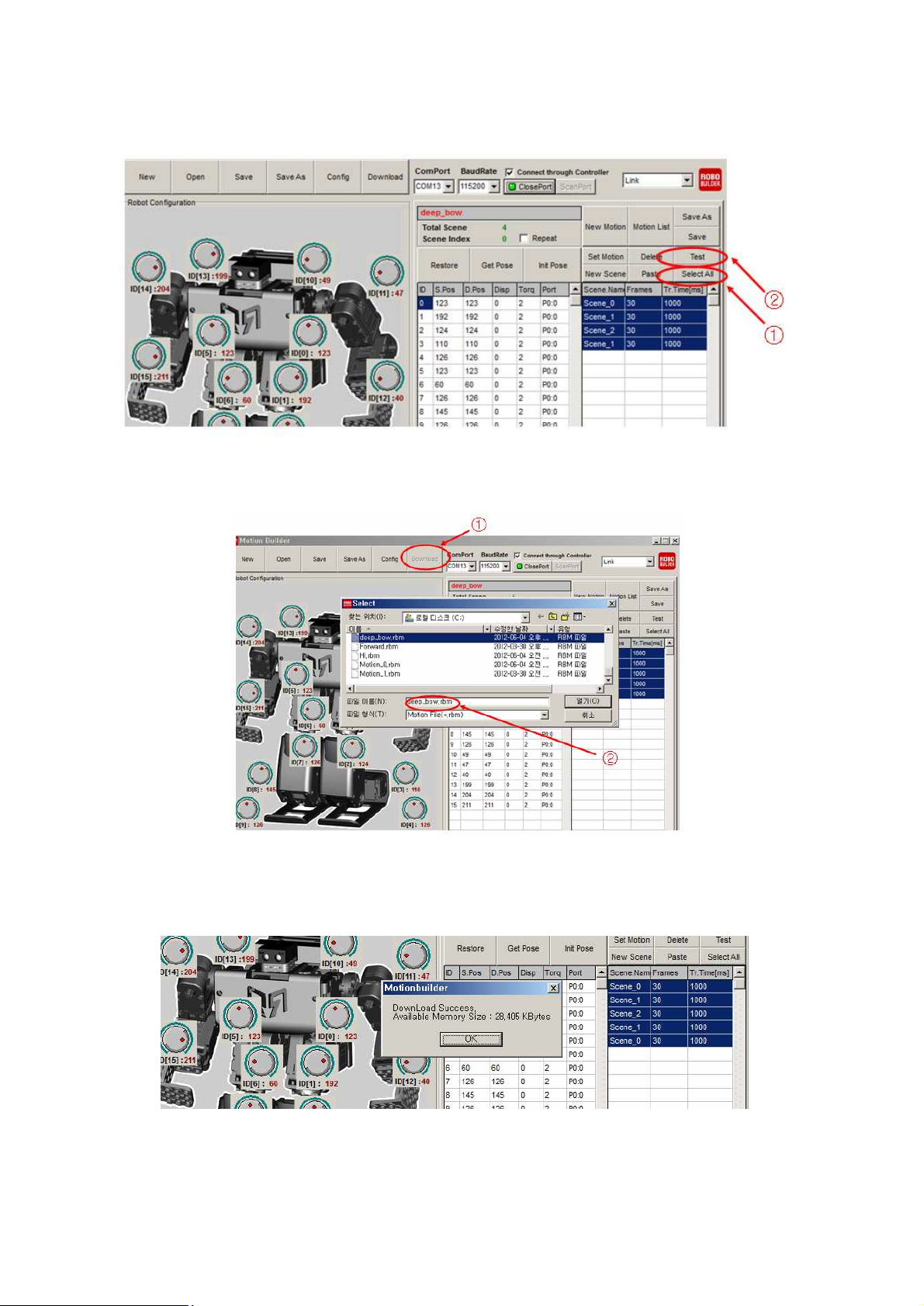
14) Now, click “Select All” and then click “Test”.
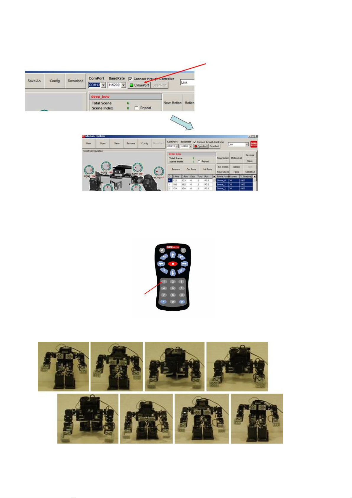
15) Click “Save” to save a “deep_bow.rbm” file.
16) “deep_bow.rbm” motion is downloaded successfully.
Page 76
76
17) Click “Close Port” to control RQ-HUNO by IR remote controller
’
18) Press button 1 of IR remote controller, “deep_bow.rbm” motion is played.
19) Completed “Hi.rbm” motion movement is as follows.
Page 77
77
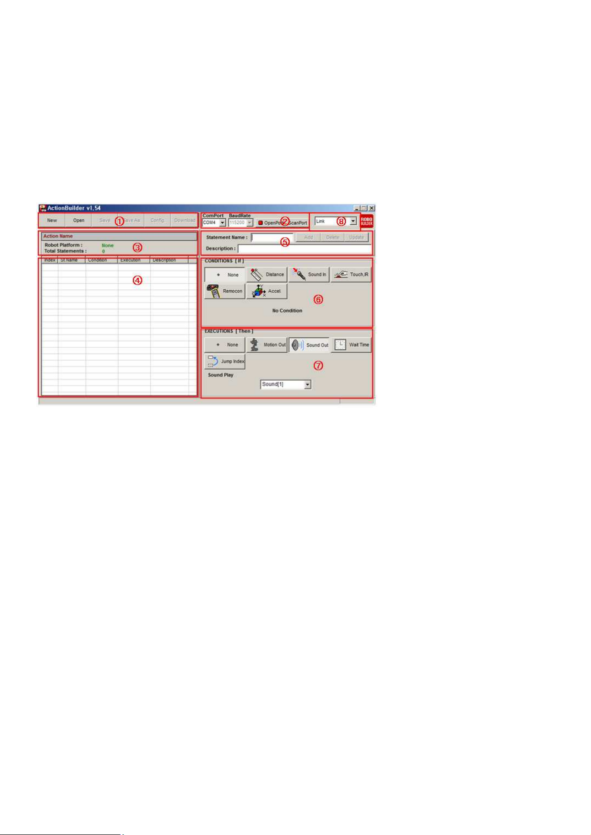
7. ActionBuilder
7.1 Introduction
ActionBuilder is the robot action programming software that uses various sensors of robot.
Layout
.
① Menu Bar
- New File : Create new action file.
- Open : Load existed action file.
- Save : Save action file.
- Save As : Save action file with new name.
- Config : Revise action file information.
- Download : Download action file to RQ smart controller
② PC COM Port
- COM Port : Choose correct COM Port.
- Baudrate : Display data communication speed.
- OpenPort : Open COM Port connect PC with RQ HUNO.
- ScanPort : Scan correct COM Port automatically.
- Config : Revise action file information.
③ Action Information
- Action Name : Display action file name.
- Robot Platform : Display action file robot platform.
- Total Statements : Display action file line numbers.
Page 78

78
④ Action list
- Index : Display action line index.
- St. Name : Display statement name.
- Condition : Display condition data.
- Execution : Display execution data.
- Description : Display description of statement.
⑤ Action Information
- Statement Name : Display statement name and user can revise it.
- Description : Display description of statement.
- Add : Add action statement from list
- Delete : Delete action statement from list.
- Update : Update action statement from list.
⑥ CONDITIONS [If]
- None : No condition
- Distance : Distance condition (unit : cm, 10~50cm)
- Sound : Sound condition (0~255, General clapping sound value is 10~15)
- Touch, IR : Input from button
- Remocon : Input from IR / Joystick remote controller
- Accel : Input X,Y,Z acceleration value
⑦ EXECUTIONS [Then]
- None : No execution
- Motion Out : Run motion
- Sound Out : Run sound
- Wait Time : Wait for designated time.
- Jump Index : Jump to designated index.
Page 79
79
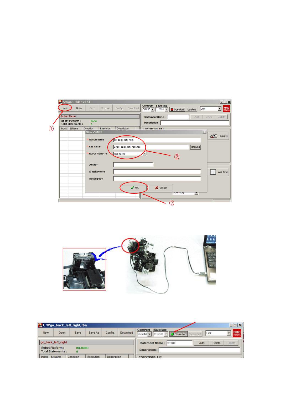
7.2 Action Programming #1 (Continuous Motions)
- Robot Action : Basic Posture => Go => Back => Left => Right.
1) Click “New” to create new action file, then input “Action Name, File Name” and select
“RQ-HUNO” platform as the below.
2) Connect RQ-HUNO with PC by using “Down Cable (UART)” then, power on smart
controller.
3) Click “Open Port”.
Page 80
80
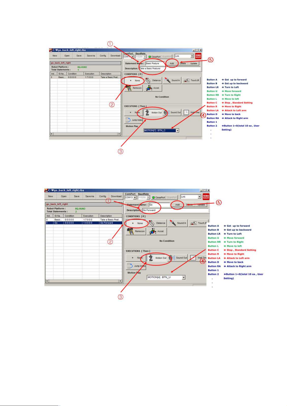
4) Click as the below procedures (1,2,3,4,5) by number to add robot basic posture motion..
5) Click as the below procedures (1,2,3,4,5) by number to add robot “go” motion.
Page 81

81
6) Click as the below procedures (1,2,3,4,5) by number to add robot “back” motion.
7) For “Left” and “Right” motion, it is same procedures except “Motion Play” section.
8) Click below procedures (1,2,3) to save action file and download to RO smart controller.
Page 82
82
9) Press “#” + “1” of IR remote controller, then robot moves “Basic Posture => Go
forward=> Backwards
=> Move Left => Move Right)
7.3 Action Programming #1 (Using Sound Sensor)
- Robot Action : Ready => If applause detected, move forward
Page 83
83
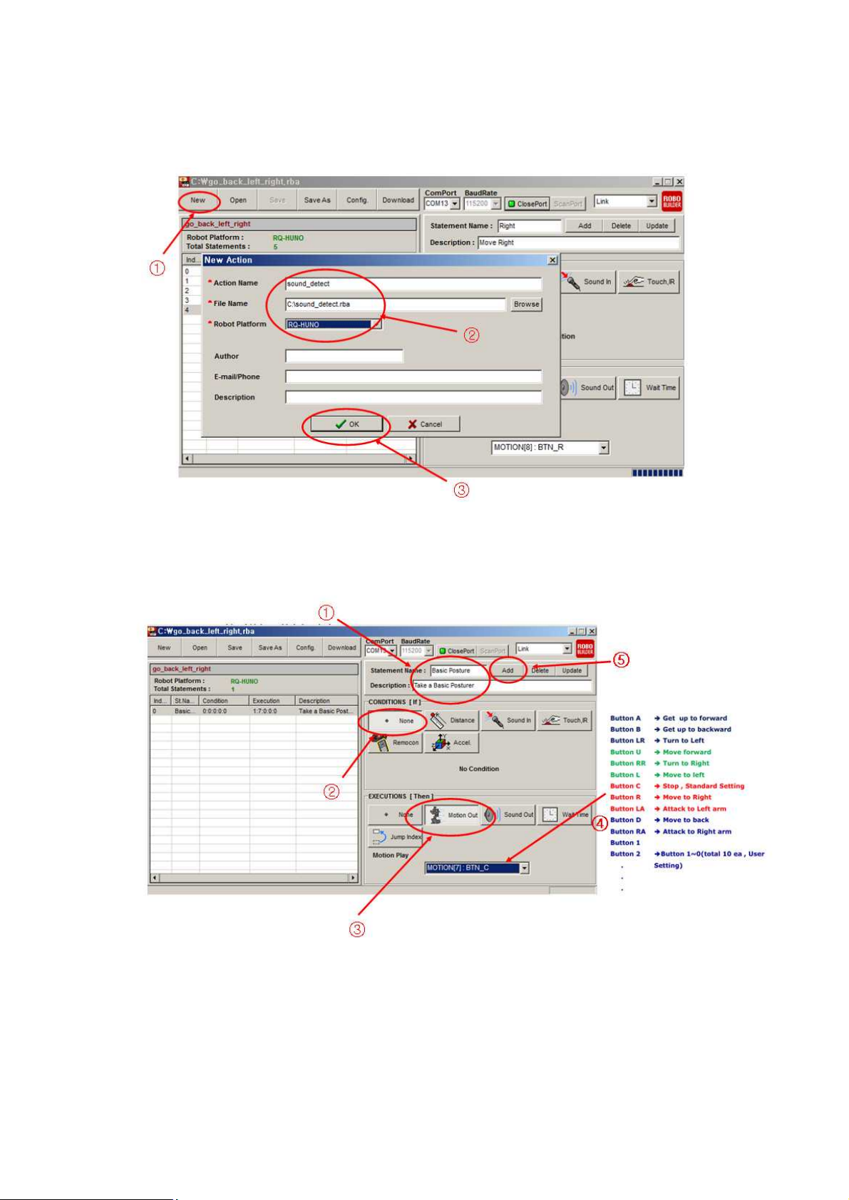
1) Click “New” to create new action file, then input “Action Name, File Name” and select
“RQ-HUNO” platform as the below.
2) Click as the below procedures (1,2,3,4,5) to add “basic posture” motion.
Page 84
84
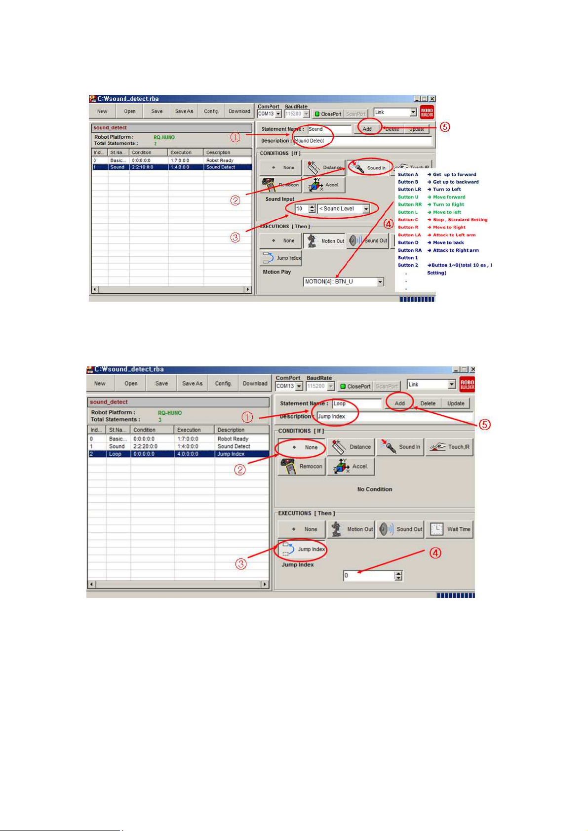
3) Click as the below procedures (1,2,3,4,5) to detect applause sound and add “go forward”
motion.
4) Click as the below procedures (1,2,3,4,5) to be in “infinite loop” state.
Page 85
85
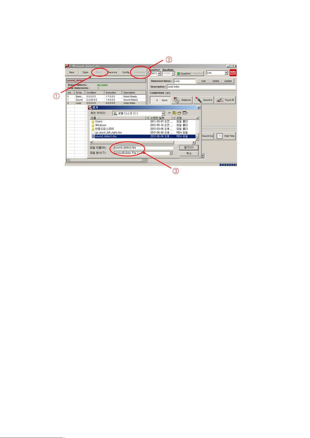
5) Click below procedures (1,2,3) to save action file and download to RO smart controller.
6) Press “#” + “2” of IR remote controller, then clap near RQ smart controller.
Page 86
86
8. Appendix
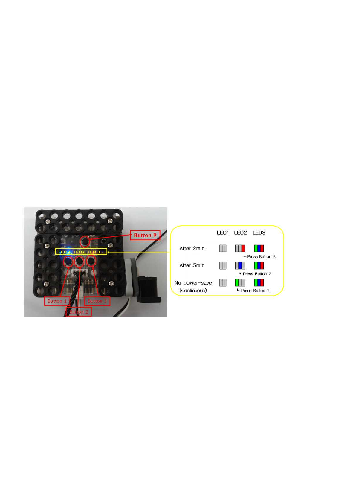
8.1 Auto power-saving mode
If there is no input or movement during certain time, RQ-HUNO goes into power-saving mode
automatically. You can set the entry time as below.
1) Power-off the smart controller.
2) Press button 3 and then, press button P concurrently.
→ LED3 "Green, Blue and Red" light up.
3) You can adjust the power-saving entry time as shown in the below.
4) Press “Button P” to save current setting after selecting power-saving entry time.
Page 87
87
8.2 How to change Smart Servo ID Number
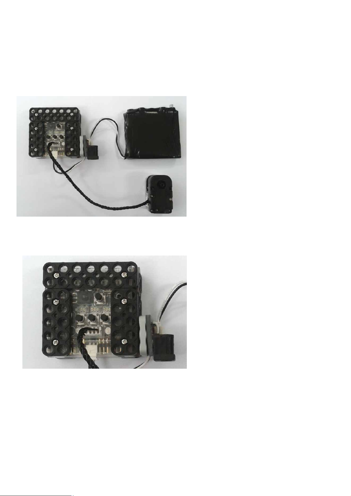
1) Connect single smart servo cable as shown in the below.
2) Make sure that Smart Controller power is “OFF” state.
Page 88
88
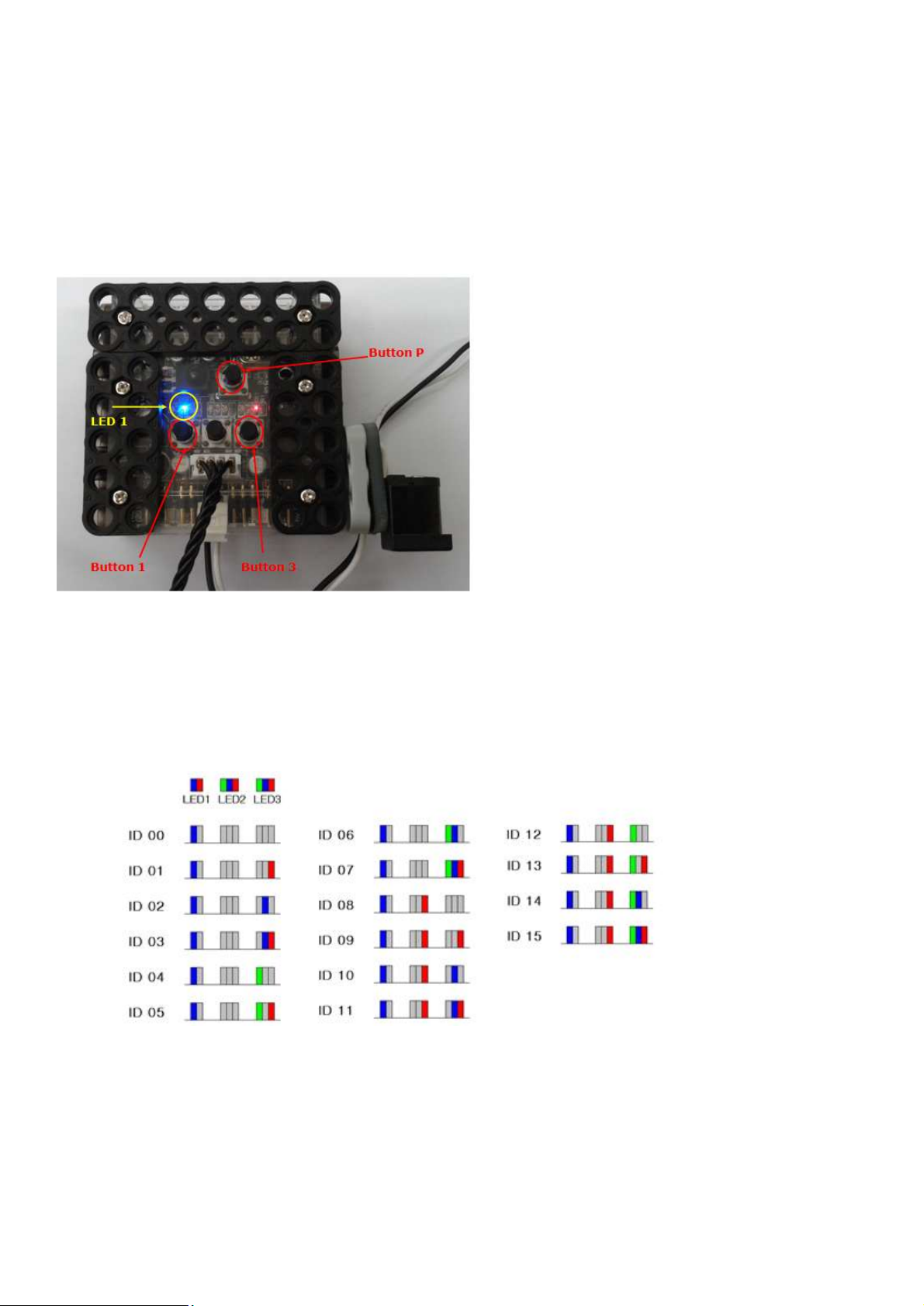
3) Press “Button P” as “Button 1” and “Button 3” are pressed together.
You can see “LED 1” is BLUE light. LED2 and LED3 indicates current Smart Servo ID. Yo
You can change Smart Servo ID by pressing “Button 1” or “Button 3”.
- Button 1 is to increase Smart Servo ID number.
- Button 2 is to cancel Smart Servo ID changes.
- Button 3 is to decrease Smart Servo ID number.
4) Press “Button P” to save current Smart Servo ID after change ID number.
Page 89
89
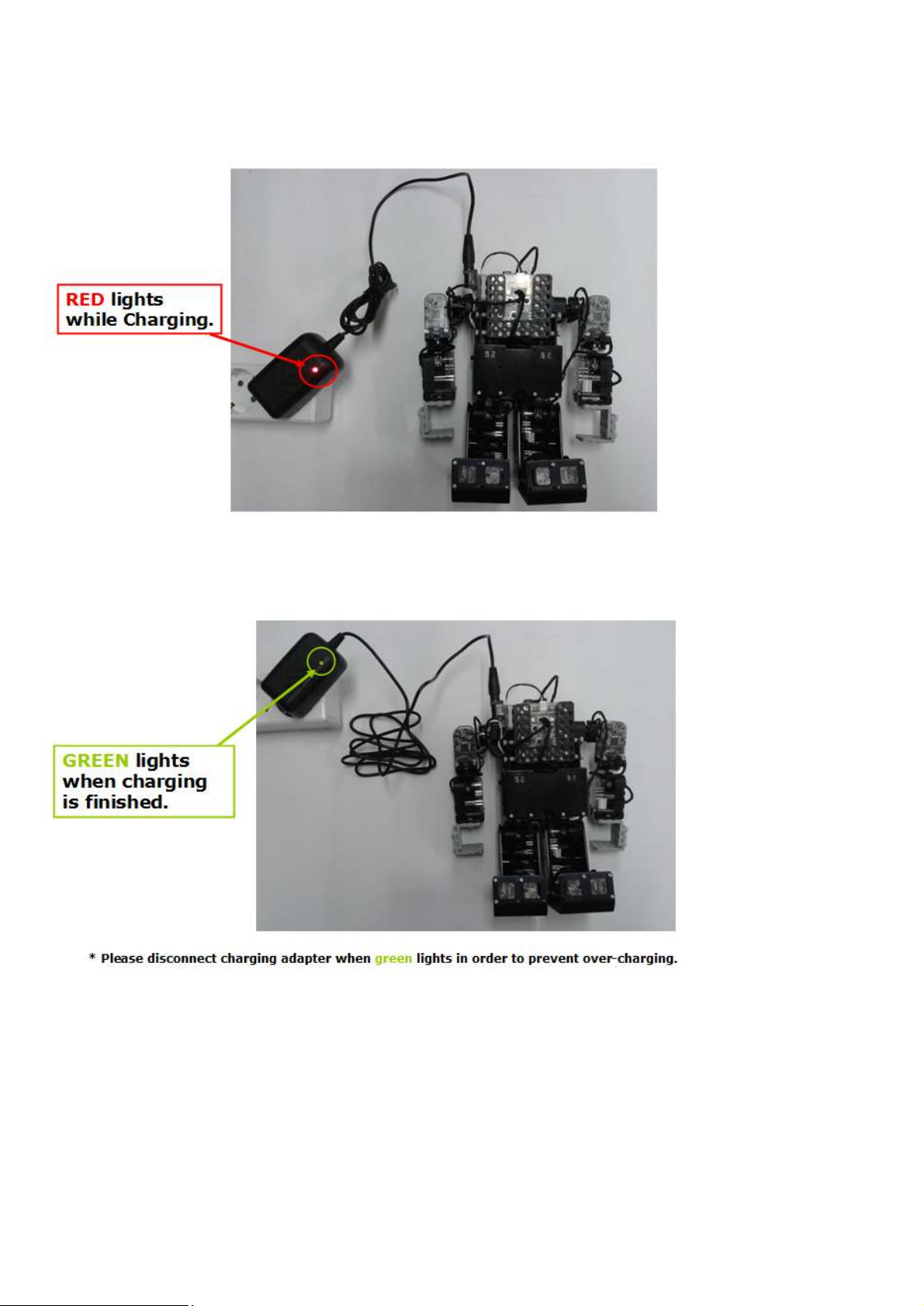
8.3 How to charge
 Loading...