

Page 1

USER’S GUIDE
RoboBuilder Co., Ltd.
Innovative DIY Robot kit with Motion File Shared on the Internet
Age 14 and up
Page 2

Page 3

4
Safety Instructions
Be cautious when assembling and using ROBOBUILDER kit for safety reasons.
This is especially important as ROBOBUILDER is a DIY assembly kit which users will
frequently build and disassemble, some of these components cause harm to the user.
The user should assume all responsibility for any accident caused by their careless
handling of the product. Attention must be paid to the following safety instructions.
Please read through this user’s guide and make sure you fully understand all the
instructions before assembling and operating this product.
Handling Electric Power
·Do not use any damaged power cord, plug, or loose outlet.
It may cause an electric shock or fire.
·Make sure that the power plug is inserted firmly into the outlet so that the power cord
can’t get loose. A loose connection may cause a fire.
·Do not forcibly bend or pull the power cord or place it under a heavy object.
It may cause an electric shock or fire.
·Do not handle the power cord with wet hands. It may cause an electric shock.
·Do not connect multiple electric devices to one outlet.
It may cause an abnormal heat or fire.
If this instruction is not properly followed, a serious injury, harm, or death may occur
to the user
If this instruction is not properly followed, an injury to user or physical damage may
arise.
Caution
·This product is not waterproof. Never operate the product in a wet place.
·Do not keep or operate the product in direct sunlight.
Caution
Warning
Warning
Page 4

5
Safety Instructions
·Do not assemble the product when you are tired or in a bad physical condition,
particularly whilst intoxicated.
·Do not place your face too close to the robot.
·Do not use dangerous tools such as a knife or a drill but only recommended tool.
·Keep the remote control that contains batteries away from children’s reach.
Should your child swallow a battery, consult with a doctor immediately.
·Do not keep or operate the robot in a place of high temperature or humidity.
·Keep small parts such as bolts, nuts, and joints away from children’s reach.
Should your child swallow any product part, consult with a doctor immediately.
Handling RoboBuilder Kit
·This product is available only for users aged 14 and up.
·Use the product only in an indoor environment.
·Do not arbitrarily disassemble, repair, and modify the product parts.
·Do not connect or disconnect cables while the robot product is in operation.
It may cause a damage or failure to the product.
·Make sure that only designated devices be connected to connectors or connection
ports of the product. It may cause a damage or failure to the product.
·When cleaning the product, do not use water or solvent such as benzene, and
alcohol but use a soft and dry cloth only. It may cause a failure to the product.
·Keep the robot or parts away from children’s reach.
·Do not leave the product with power on.
Battery damage may cause a product failure.
·Accumulated gear backlash may cause abnormal robot actions if the product is
operated for a long time or executes repeatedly excessive motions, which can
transmit mechanical overload stress to wCK actuator modules.
·Do not give excessive force while a torque is applied to the wCK actuators of the
robot. A gear damage may cause a product failure.
·In some cases wCK actuator module can vibrate a little under operation.
This is not a product failure but a phenomenon that is caused by improper
settings of gains and torque values of the wCK modules. When you set proper
values for them, this phenomenon disappears.
·When wCK actuator modules get twisted by running wrong motions while
programming, turn the power off quickly to prevent excessive torque from being
transmitted to the robot.
·If your finger is caught between actuator modules, turn the power off quickly and
remove force applied to robot to prevent any physical injury.
·Do not operate and let the robot touch any human life or animal.
It may cause injury to the life or product failure.
Caution
Warning
Page 5

Safety Instructions 4
Chapter 1.
Introduction to RoboBuilder 7
Product Features 8
Robot File Sharing on Internet 9
KIT Part List 10
Standard Robot Platforms 11
HUNO 11
DINO 12
DOGY 13
Play Guide 14
KIT Models 14
Chapter 2.
Assembling RoboBuilder 15
Before Assembly 16
Transformation of RoboBuilder 20
HUNO 22
Upgrade HUNO 36
DINO 38
DOGY 52
Chapter 3.
Operating RoboBuilder 65
Installing the Software 66
Software Components 68
MotionBuilder 68
RBC Upgrade Tool 70
Connecting RoboBuilder with PC 71
Checking PC serial port 71
Checking Robot Platform 72
Operating Control Box 73
Using Remote Control 74
Programming 75
Creating New Robot File 76
Modifying Robot File. 81
Quick & Easy Motion-Teaching
Programming Method 84
Modifying Downloaded Robot File 86
Transferring Robot File to Control Box 88
Playing with Robot 90
Recharging Battery 91
Replacing Battery 92
Setting Home Posture 93
Using the Package Tray 93
Adjusting Home Posture Manually 97
Manipulating Home Posture File 100
Upgrading Firmware 101
Chapter 4.
Troubleshooting 103
Table of Contents
Page 6

RoboBuilder is a DIY robot with multiple axes and
multiple functions, which is built by joining various
parts such as wCK robotic module, controller, joints,
and other body parts.
Users can build three standard robot platforms (HUNO,
DINO, and DOGY) for which building instructions are
provided with the kit. Various other robots of user’s
own design can also be easily created.
The robot can easily perform complex motions by
running robot files that are programmed by user or
from robot files that can be downloaded from the Internet.
Chapter 1.
Introduction to RoboBuilder
Page 7

8
Product Features
Short Building Time
Approximately 1 hour building is required to create a robot that is ready to run with
advanced functions and 16 degrees of freedom.
Robot File Sharing
The robot files that define a robot’s motions and actions can be shared over Internet.
(Realized for the first time in the world through precise motion control technology)
Quick & Simple Joint Assembly
Various types of joints enable the user to quickly build new articulated robotic creatures.
Precise Motion Control
Smooth and Natural motions realized through precise motion control both in wheel
mode (360˚) and position control mode(0 to 332˚).
Distributed Controls
Quick and Easy troubleshooting and upgrading are ensured as the main
control(control box) and remote control(wCK joint actuators)are separated.
Built-in Connector
You can easily connect signal line and power line by using two built-in connectors
installed on the wCK module.
Attractive Design
RoboBuilder has an attractive design with curved body lines.
The user can customize their unique robots with various optional accessories.
Creative Robot Building
You can make any desired robot with your own ideas and designs as well as three
standard robot platforms.
Page 8

9
Chapter 1. Introduction to RoboBuilder
Robot File Sharing on Internet
RoboBuilder has adopted the technology of sharing robot files on internet for the first time in the
world. A robot file uploaded on internet by a user can be downloaded and run by another user.
This new technology enables multiple robots with the same hardware structure to share motions
through the Internet.
To upload and download robot files, access the RoboBuilder homepage
(http://www.RoboBuilder.net) and go to COMMUNITY page.
ㆍ Motion files created by a user with MotionBuilder can be shared online as well as offline. However, any motion
files that are modified after being downloaded must but uploaded back to the RoboBuilder homepage if the user
wishes to share these with other users.
ㆍ All downloaded motion files from the homepage may not work perfectly when executed in a different user’s robot.
ㆍ In order to modify downloaded motion files, the user should first add the file to a project in MotionBuilder.
Page 9

10
KIT Part List
The Parts included in a RoboBuilder kit are as follows:
wCK module ×16
Body Frame ×1 Chest Cover ×1 Foot Part ×2
Hand Part ×2
Head Part ×1
(Sensor Module)
wCK module Cable ×20
J2
×8
J1
×2
J3
×3
Control Box ×1
Leg Cover ×2
B5 ×12 B16 ×24B12 ×17
B8 ×15
Nut ×84
B40 ×66
Shoe Plate ×2
Power Supply ×1
PC Cable ×1
Remote Controller ×1
J6
×7
J5
×1
J7
×3
J9
×1
J8
×1
J11
×5
J12
×2
J4
×3
J10
×3
B6 ×9
Software CD ×1 User’s guide ×1
User’s guide
B Gold ×10
※The parts within this product are subject to change without notice, this may occur
if the design of the product changes or is improved.
Page 10

11
Chapter 1. Introduction to RoboBuilder
Standard Robot Platforms
The specifications of three standard robot platforms(HUNO, DINO, and DOGY) are as follows:
HUNO
170
105
105 170
285
Item Specifications
Size (mm)
Approx. 285 (H) x 170 (W) x 105 (D)
Weight (kg)
1.25
Degree of freedom
16
Power
Battery: 8.4V Ni-MH
Power adapter: 12V
Controller
Atmega 128
External case
Engineering plastic
Battery operating time
Approx. 10 - 30 minutes
Introduction
HUNO is a humanoid walking robot designed to resemble a human being. This robot is one of
the best robots that can be built with RoboBuilder kit. A simple remote control can be used to
initiate basic motions such as walking, running, kicking, and a hand stand. The user can also
enjoy more complex motions such as dancing, performing Taekwon-do, responding to sounds,
and detecting objects by programming new robot files.
Page 11

12
DINO
180
170
180
285
170
Item Specifications
Size (mm)
Approx. 285 (H) x 170 (W) x 180 (D)
Weight (kg)
1.25
Degree of freedom
16
Power
Battery: 8.4V Ni-MH
Power adapter: 12V
Controller
Atmega 128
External case
Engineering plastic
Battery operating time
Approx. 10 - 30 minutes
Introduction
DINO is a three-legged robot designed to resemble a dinosaur This robot can perform
fun motions using its tail. It can move faster than the HUNO and can use it’s tail to demonstrate various motions. The user can enjoy entertaining motions such as dancing,
tail show, tail attacks, responding to sounds, and detecting objects by programming
new robot files.
Page 12

13
Chapter 1. Introduction to RoboBuilder
DOGY
215
170
260
215 170
Item Specifications
Size (mm)
Approx. 260 (H) x 170 (W) x 215 (D)
Weight (kg)
0.9
Degree of freedom
16
Power
Battery: 8.4V Ni-MH
Power adapter: 12V
Controller
Atmega 128
External case
Engineering plastic
Battery operating time
Approx. 10 - 30 minutes
Introduction
DOGY is a four-legged walking robot designed to resemble a dog. This robot can move
the fastest amongst the three standard robots. The user can enjoy entertaining motions
such as push-ups, handstands, standing on two legs, rolling, etc. The user can also
program motions so that the robot responds to sounds and object detection.
Page 13

14
Play Guide
KIT Models
Below are the RoboBuilder kit models available for order :
Model
wCK Module
Color
Sound
Recognition
Speaker
Degree of
Freedom
Actuator
Torque
Distance
Sensor
LED on
Actuator
CREATOR
5710K
Black Y
N
16
8kg·cm-12 EA
11kg·cm-4 EA
N N
CREATOR
5720T-S02
Transparent Y Y 16
8kg·cm-12 EA
11kg·cm-4 EA
Y Y
EXPERT
5730K
Black Y Y
Y N
Page 14
This Chapter provides the user with the required
procedures and skills needed to assemble the
three different standard robot platforms(HUNO,
DINO, and DOGY).
The user can apply the same information andknowledge to create their own robots using thesame parts included in the package.
Chapter 2.
Assembling RoboBuilder
Page 15

16
[HUNO Basic Posture]
[DINO Basic Posture] [DOGY Basic Posture]
Before assembly
The user should carefully read and familiarize themselves with the instructions before
starting assembly.
A beginner should first watch the video version of building instructions, this can be found in CD or
at RoboBuilder’s homepage(www.RoboBuilder.net). The user is responsible for any damage to the
robot and its components that are the result of the user not following the instructions, any such damage will not be repaired as a warranty claim.
A user who is not able to assemble a robot for themself can contact local distributor or agent who
can provide a robot-building service(this will incur an additional cost as set by the local distributor
or agent).
The Basic Postures of the three standard robot platforms are as shown in below pictures. If a robot
doesn’t show the exact Basic Posture when you push the red button(
) on the remote controller,
the robot doesn’t move properly or the red Error lamp is turned on, then the robot may not be built
correctly or may have another problem.
In this case, please refer to Chapter 4 [Troubleshooting] to solve the problem. Always make sure that
you start the robot from the correct Basic Posture. Trying to play the robot continuously with the Error
lamp on may cause a serious product failure or damage.
(When Error lamp is turned on, the robot doesn’t take any command signals from the remote control
for 30 seconds, which is designed to protect possible damage to product.)
Page 16

17
Chapter 2. Assembling RoboBuilder
In the process of building a robot the user may encounter a situation where the rotating axis of a
wCK module is stiff and won’t move smoothly. This is not a product fault but a situation caused
by the tight arrangement of the internal gears. Tight gear arrangement is designed for precise
motion control. In this case, please refer to troubleshooting material available on the product CD
and information from our homepage to help fix the problem.
1 hour of assembly time is the average time that is required for a user who has average building
skill to build one of the three standard robot platforms. Thus the building time may vary depending
on the level of the user and work environment.
Be careful not have a nut or a bolt slip inside the control box or wCK module, this may cause a
product fault or a failure.
Page 17

18
Adjusting the rotating axis of wCK module
When assembling wCK modules, there are cases where it is required to adjust the rotating axis
of the wCK module. In this case, rotate the axis using the joint part as shown in figure below:
Putting wCK module and joint together
When putting a wCK module and a joint together, be careful to set the direction of the rotating axis
of the wCK module as shown in below:
Wrong assembly (X) Correct assembly (O)
Recommended tool
EDISON EDM 100 [precision screwdriver (+ type)]
Blade thickness 3mm, Blade length 100mm
Page 18

19
Chapter 2. Assembling RoboBuilder
How to read the building instructions
Each step of the building instructions contains the assembly sequence, parts to be used,
cautions, etc. The following is an example STEP from the building instructions.
1) Prepare the parts required for the corresponding assembly step.
(Body Frame, wCK ID 10, J2, B8, B40, Nut)
2) Connect both cables to wCK(ID10) first before attaching it to body frame.
3) Attach ID 10 to the body frame using B40(4 EA) and nuts(4 EA). (①②③④)
4) Attach J2(ⓐ) to wCK(ID 10) using B8(1 EA). Follow caution to correctly set the axis angle. (⑤)
5) Arrange cables as shown in the picture.
Caution area requires special attention
When putting some wCK modules and joints together, adjusting
the alignment angle is important.
In this case, adjust the axis angle of the wCK module correctly
by following the illustration shown in the CAUTION picture.
A red highlight is added to help highlight this.
If not assembled as shown in the picture, it may cause
abnormal operation or a failure.
The angle adjustment is
critically important.
① displays the STEP number.
② displays the position of assembly.
(Left or right from the robot’s view point)
③ displays the information on bolts and joints required
for the step.(B40: 40mm Bolt, J2: Joint 2)
④ displays the ID number of the wCK module.
⑤ displays the caution area in which user should pay
more attention.
⑥ The joint part information.
⑦ displays the position of the inserted nut.
⑧ displays the assembly sequence.
⑨ illustrate the caution area (⑤)to help clear understanding.
STEP 01
Left
Connect both wCK cables first
before attaching it to body frame.
ⓐ
①
②
③
④
The adjustment of
connecting angle is
critically important.
ID 10
①②③④ : B40, ⑤ : B8
ⓐ : J2
ID 10
⑤
①
②
③
④
⑤
⑥
⑦
⑧
⑨
Page 19

20
Transformation of RoboBuilder
DOGY
The RoboBuilder kit has been designed for users to easily transform a robot to another standard
platform robot. For example, by reassembling some parts of a HUNO the user can transform it into
a DOGY in approximately 30 minutes. When the robot transformed from the HUNO to DOGY, the
PF LED on the control box must be set to change the platform type - then the DOGY is ready for
action and can be controlled by the remote control. The sound generated by the
robot is automatically changed for the various standard platforms.
Page 20

21
Chapter 2. Assembling RoboBuilder
HUNO
DINO
Page 21

22
HUNO
HUNO’s name comes from Humanoid as it resembles the appearence of a human
being. The assembly of HUNO consists of total 20 steps. The required parts for each
step and the related assembly instructions are provided here.
Completed HUNO
Page 22

23
Chapter 2. Assembling RoboBuilder
HUNO Part List
wCK module ×16
Body Frame ×1
Chest Cover ×1
Foot Part ×2
Hand Part ×2
Head Part ×1
(Sensor Module)
wCK module Cable ×16
J4
×2
J2
×6
J6
×4
Control Box ×1
Shoe Plate ×2 Leg Cover ×2
B5 ×8 B16 ×16B12 ×10B8 ×9Nut ×56 B40 ×40
※The components within this product are subject to change without notice, this may occur if the design of the
product changes or is improved.
B Gold ×3
H
U
N
O
B6 ×7
Page 23

24
Assembly Sequence
STEP 01, 02, 03, 04
01
STEP 05, 06
02
STEP 07, 08
03
STEP 09, 10
04
STEP 11, 12
05
STEP 13
06
All building instructions for HUNO are exactly the same as the ones for DINO except for the arms
and the tail.
STEP 14
07
STEP 15, 16
08
Page 24

25
Chapter 2. Assembling RoboBuilder
ID MAP
Front View Rear View
The ID map of the wCK robot modules for HUNO are as follows:
11 14
1512
1310
06
01
0500
07
02
0803
0904
14
15
11
12
13 10
06
01
05 00
07
02
08 03
09 04
STEP 17
09
STEP 18, 19, 20
10
H
U
N
O
Page 25

26
STEP 01
Right
Connect both wCK cables first
before attaching it to body frame.
ⓐ
⑤
①
②
③
④
STEP 02
ID 13
Left
Connect both wCK cables first
before attaching it to body frame.
ⓐ
①
②
③
④
ID 10
①②③④ : B40, ⑤ : B8
ⓐ : J2
①②③④ : B40, ⑤ : B8
ⓐ : J2
ID 10
ID 13
⑤
The adjustment of the
connecting angle is critically
important.
The adjustment of the
connecting angle is critically
important.
8mm Bolt
40mm Bolt
Joint 2
Page 26

27
Chapter 2. Assembling RoboBuilder
①
②
③
④
STEP 03
Right
STEP 04
⑤
①
②
③
④
Left
The adjustment of the
connecting angle is
critically important.
ID 00
ⓐ
The adjustment of the
connecting angle is
critically important.
ID 05
ⓐ
①②③④ : B40, ⑤ : B8
ⓐ : J2
Connect both wCK cables first
before attaching it to body
frame.
①②③④ : B40, ⑤ : B8
ⓐ : J2
Connect both wCK cables first
before attaching it to body
frame.
ID 00
ID 05
⑤
H
U
N
O
Page 27

28
①
②
⑦
ID 14
ID 15
STEP 05
STEP 06
①
②
ID 11
ID 12
ⓐ
⑦
⑤
⑥
③
④
ID 12
ⓑ
Left
①②③④⑤⑥ : B16, ⑦ : B12
ⓐ : J6, ⓑ : J4
Right
①②③④⑤⑥ : B16, ⑦ : B12
ⓐ : J6, ⓑ : J4
③
④
⑦
⑤
⑥
ID 15
ⓐ
ⓑ
ⓐ
⑦
ⓐ
Page 28

29
Chapter 2. Assembling RoboBuilder
ID 06
ID 07
ID 08
STEP 07
ID 01
ID 02
ID 03
Connect wCK cables as
above before attaching leg
cover.
Left
Connect wCK cables as
above before attaching
leg cover.
Right
STEP 08
②
①
⑪
①② : B16, ③④⑤⑥⑦⑧⑨⑩ : B40, ⑪ : B12
ⓐ : J6
①② : B16, ③④⑤⑥⑦⑧⑨⑩ : B40, ⑪ : B12
ⓐ : J6
ⓐ
ID 02
ID 03
ID 07
ID 08
⑩
⑨
⑧
⑦
⑥
⑤
④
③
⑪
②
①
⑩
⑨
⑧
⑦
⑥
⑤
④
③
※The pentagon-shaped rotation axes of
wCK ID01,02,03 should all face to same
direction(outwards)
※The pentagon-shaped rotation axes of
wCK ID06,07,08 should all face to same
direction(outwards)
ⓐ
H
U
N
O
Page 29

30
STEP 09
Left
STEP 10
①②③④ : B5, ⑤⑥⑦⑧ : B40
ID 04
⑧
⑦
⑥
⑤
④
③
②
①
R i g h t
①②③④ : B5, ⑤⑥⑦⑧ : B40
ID 09
⑧
⑦
⑥
⑤
④
③
②
①
※ Make sure that the front side of the
shoe plate has a narrower width of
its folded surface than rear side.
※ Make sure that the front
side of the shoe plate has
a narrower width of its
folded surface than rear
side.
Page 30

31
Chapter 2. Assembling RoboBuilder
STEP 11
Right
STEP 12
Left
The adjustment of the connecting
angle is critically important.
The adjustment of the connecting
angle is critically important.
① : B8, ② : B12
ⓐ : J2
① : B8, ② : B12
ⓐ : J2
ID 03
ⓐ
ID 04
②
ⓐ
②
ⓐ
ID 09
ID 08
①
①
ID 01
ID 02
ID 06
ID 07
ID 02
ID 03
ID 07
ID 08
H
U
N
O
Page 31

32
STEP 13
STEP 14
Left, Right
②
①
①② : B12
①②③④ : B6
②
①
④
③
ID 13
ID 10
ID 13
ID 10
ID 14
ID 06
ID 01
ID 06
ID 01
ID 00
ID 05
ID 15
ID 06
ID 01
ID 05
ID 00
ID 05
ID 00
ID 13
ID 10
Page 32
33
Chapter 2. Assembling RoboBuilder
STEP 15
Right
STEP 16
Left
① : B12
① : B12
①
①
ID 13
ID 10
ID 06
ID 11
ID 10
ID 11
ID 10
ID 11
ID 13
ID 10
ID 14
ID 13
ID 14
ID 14
ID 13
ID 01
H
U
N
O
Page 33

34
STEP 17
①
STEP 18
②
①②③ : B6
Left Arm
Right Arm
Head
Left Arm
Right Leg
Left Leg
③
ID 11
ID 14
ID 12
ID 11
Left Leg
Right
Leg
Right Arm
Head
Page 34

35
Chapter 2. Assembling RoboBuilder
Right Arm
Head
Left Arm
Right Leg
Left Leg
ID 11 ID 14
ID 12 ID 15
STEP 19
With the control box half slid
down, insert the cables from
both legs to the connectors on
the control box before the control box is fully pushed down
and secured. All cables, other
than the sensor cable from the
head, can be plugged into any
of the connectors.
STEP 20
①: Power ON
②: Check PF1
Blue LED
③: Check the basic
posture (
)
※ If battery is not sufficiently charged, connect
the power adapter to run the robot.
H
U
N
O
Page 35

36
Upgrade HUNO
Upgraded HUNO is a modified platform of HUNO enhanced by adding two more degrees of
freedom(2 more wCK module). With its waist twisting freely, the various motions that can be
programmed are much more natural and human like.
Page 36

37
Chapter 2. Assembling RoboBuilder
H
U
N
O
Page 37

38
DINO
DINO’s name comes from the Dinosaur as it resembles a dinosaur with a tail. The assembly of DINO consists of 20 steps. The required parts for each step and the related
assembly instructions are provided here.
Completed DINO
Page 38

39
Chapter 2. Assembling RoboBuilder
DINO Part List
J7
×2
J2
×5
J3
×2
J4
×2
J11
×1
J6
×4
wCK module ×16
Body Frame ×1
Chest Cover ×1
Foot Part ×2
Hand Part ×2
Head Part ×1
(Sensor Module)
wCK module Cable ×16
Control Box ×1
Shoe Plate ×2 Leg Cover ×2
※The components within the product are subject to change without notice, this may occur if the design of the
product changes or is improved.
B Gold ×3
B5 ×8 B16 ×16B12 ×11B8 ×9Nut ×56 B40 ×44
D
I
N
O
B6 ×7
Page 39

40
Assembly sequence
STEP 01, 02, 03, 04
01
STEP 05
02
STEP 06, 07, 08, 09,
10, 11
03
STEP 15
07
STEP 16
08
STEP 12
04
STEP 13
05
STEP 14
06
All building instructions for DINO are exactly the same as the ones for HUNO except for the arms and the tail.
Page 40
41
Chapter 2. Assembling RoboBuilder
ID MAP
STEP 17
09
STEP 18, 19, 20
10
Front View Rear View
The ID map of the wCK robot modules for DINO are as follows:
13
11
12
14
15
09 04
06
05
07
08
10
01
00
02
03
10
11
12
14
15
04 09
01
00
02
03
13
06
05
07
08
D
I
N
O
Page 41

42
STEP 01
Right
Connect one wCK cable first as above
before attaching it to body frame.
ⓐ
①
②
③
④
STEP 02
ID 13
Left
Connect one wCK cable first as above
before attaching it to body frame.
ⓐ
①
②
③
④
ID 10
①②③④ : B40, ⑤ : B8
ⓐ : J3
①②③④ : B40, ⑤ : B8
ⓐ : J3
ID 10
ID 13
⑤
⑤
The adjustment of the
connecting angle is critically
important.
8mm Bolt
40mm Bolt
Joint 3
The adjustment of the
connecting angle is critically
important.
Page 42

43
Chapter 2. Assembling RoboBuilder
①
②
③
④
STEP 03
Right
STEP 04
①
②
③
④
Left
ID 00
ⓐ
ID 05
ⓐ
①②③④ : B40, ⑤ : B8
ⓐ : J2
Connect both wCK cables first
before attaching it to body
frame.
①②③④ : B40, ⑤ : B8
ⓐ : J2
Connect both wCK cables first
before attaching it to body
frame.
ID 00
ID 05
⑤
⑤
ID 10
ID 13
ID 13
ID 10
The adjustment of the
connecting angle is
critically important.
D
I
N
O
The adjustment of the
connecting angle is
critically important.
Page 43

44
STEP 06
ID 01
ID 02
ID 03
Connect wCK cables as above
before attaching leg cover.
Left
⑪
①② : B16, ③④⑤⑥⑦⑧⑨⑩ : B40, ⑪ : B12
ⓐ : J6
ⓐ
ID 02
ID 03
STEP 05
Left
①② : B16
ⓐ : J7, ⓑ : J4
①
②
ⓐ
ⓑ
③
Right
①② : B16
ⓐ : J7, ⓑ : J4
①
②
ⓐ
ⓑ
③
②
①
⑩
⑨
⑧
⑦
⑥
⑤
④
③
※The pentagon-shaped rotation axes of
wCK ID01,02,03 should all face to same
direction(outwards)
Page 44

45
Chapter 2. Assembling RoboBuilder
ID 06
ID 07
ID 08
Connect wCK cables as
above before attaching leg
cover.
Right
STEP 07
②
①
①② : B16, ③④⑤⑥⑦⑧⑨⑩ : B40, ⑪ : B12
ⓐ : J6
ID 07
ID 08
⑩
⑨
⑧
⑦
⑥
⑤
④
③
ⓐ
⑪
STEP 08
Left
①②③④ : B5, ⑤⑥⑦⑧ : B40
ID 04
⑧
⑦
⑥
⑤
④
③
②
①
※ The pentagon-shaped rotation axes
of wCK ID06,07,08 should all face to
same direction(outwards)
※ Make sure that the front
side of the shoe plate has a
narrower width of its folded
surface than rear side.
D
I
N
O
Page 45
46
STEP 10
Left
① : B8, ② : B12
ⓐ : J2
ID 03
ⓐ
ID 04
②
ⓐ
①
ID 01
ID 02
ID 02
ID 03
STEP 09
Right
①②③④ : B5, ⑤⑥⑦⑧ : B40
ID 09
⑧
⑦
⑥
⑤
④
③
②
①
The adjustment of the connecting
angle is critically important.
※ Make sure that the front side of the shoe
plate has a narrower width of its folded
surface than rear side.
Page 46

47
Chapter 2. Assembling RoboBuilder
Right
STEP 11
① : B8, ② : B12
ⓐ : J2
②
ⓐ
ID 09
ID 08
①
ID 06
ID 07
ID 07
ID 08
STEP 12
① : B8, ②⑤⑧ : B12, ③④⑥⑦⑨⑩ : B16
ⓐ : J2, ⓑⓒ : J6, ⓓ : J11
②
③
④
⑤
ID 12
ID 11
ID 14
ⓑ
⑥
⑦
⑧
⑨
⑩
ID 14
ID 15
ⓑ
ⓓ
①
ⓐ
The adjustment of the connecting
angle is critically important.
ⓒ
D
I
N
O
Page 47

48
STEP 14
Left, Right
②
①
①② : B12
ID 06
ID 01
ID 06
ID 01
ID 00
ID 05
ID 06
ID 01
ID 05
ID 00
ID 05
ID 00
ID 13
ID 10
STEP 13
①②③④ : B6
②
①
④
③
ID 13
ID 10
ID 13
ID 10
Page 48

49
Chapter 2. Assembling RoboBuilder
STEP 15
ID 13
ID 10
STEP 16
①
③
②
①②③ : B6
Right Front Leg
Head
Left Front Leg
Left
Rear Leg
Right
Rear Leg
D
I
N
O
Page 49

50
STEP 18
STEP 17
①
③
④
②
①②③④ : B40
ID 01
ID 06
ID 11
ID 12
ID 02
ID 07
Page 50

51
Chapter 2. Assembling RoboBuilder
STEP 19
Head
Left Front Leg
Left Rear Leg
Left
Rear Leg
Right
Rear Leg
Tail
With the control box half slid
down, insert the cables from
both legs to the connectors on
the control box before the control box is fully pushed down
and secured. All cables, other
than the sensor cable from the
head, can be plugged into any
of the connectors.
STEP 20
①: Power ON
②: Check PF1
Pink LED
※ If battery is not sufficiently charged connect
the power adapter to run the robot.
③: Check the basic
posture (
)
D
I
N
O
Page 51

52
DOGY
DOGY’s appearance resembles that of a dog.
The assembly of DOGY consists of 18 steps. The required parts for each step and
the related assembly instructions are provided here.
Completed DOGY
Page 52

53
Chapter 2. Assembling RoboBuilder
DOGY Part List
J10
×1
J2
×4
B6 ×2
B16 ×18B12 ×11B8 ×9Nut ×32 B40 ×16
J11
×4
J6
×5
Body Frame ×1
wCK module ×16
Control Box ×1
wCK module Cable ×16
Sensor Module ×1
J12
×2
※The components within the product are subject to change without notice, this may occur if the design of the
product changes or is improved.
B Gold ×5
D
O
G
Y
Page 53

54
Assembly Sequence
STEP 01, 02, 03, 04
01
STEP 05, 06
02
STEP 07
03
STEP 08
04
STEP 09, 10
05
STEP 11, 12
06
STEP 13
07
STEP 14
08
Page 54

55
Chapter 2. Assembling RoboBuilder
ID MAP
STEP 15
09
STEP 16, 17, 18
10
Bottom View Back View
The ID map of the wCK robot modules for DOGY are as follows:
14
15
09
06
11
12
04
01
07
08
02
03
13
05
10
00
13
11
12
14
15
0904
06
05
07
08
10
01
00
02
03
D
O
G
Y
Page 55

56
STEP 01
Right
The adjustment of the
connecting angle is
critically important.
STEP 02
Left
ⓐ
①
②
③
The adjustment of
the connecting angle is
critically important.
ID 05
①②③ : B40, ④ : B8
ⓐ : J2
①②③ : B40, ④ : B8
ⓐ : J2
①
②
③
④
④
ⓐ
ID 00
Connect both wCK cables first
before attaching it to body frame.
ID 05
ID 00
Connect both wCK cables first
before attaching it to body frame.
8mm Bolt
40mm Bolt
Joint 2
Page 56

57
Chapter 2. Assembling RoboBuilder
STEP 03
Right
STEP 04
Left
①②③ : B40, ④ : B8
ⓐ : J2
①②③ : B40, ④ : B8
ⓐ : J2
The adjustment of
the connecting angle is
critically important.
①
②
③
④
ⓐ
ID 05
ID 13
ID 00
①
ⓐ
ID 00
ID 10
ID 05
④
③
②
Connect both wCK cables first
before attaching it to body frame.
ID 13
ID 10
Connect both wCK cables first
before attaching it to body frame.
D
O
G
Y
The adjustment of
the connecting angle is
critically important.
Page 57

58
Right
STEP 05
①②③④ : B16, ⑤ : B12
ⓐ : J6, ⓑ : J11
Left
①②③④ : B16, ⑤ : B12
ⓐ : J6, ⓑ : J11
Left
STEP 06
①②③④ : B16, ⑤ : B12
ⓐ : J6, ⓑ : J11
Right
①②③④ : B16, ⑤ : B12
ⓐ : J6, ⓑ : J11
①
②
③
④
⑤
①
②
③
④
⑤
①
②
③
④
⑤
ID 06
ID 09
①
②
③
④
⑤
ⓑ
ID 01
ID 04
ID 14
ID 15
ID 11
ID 12
ⓐ
ⓑ
ⓐ
ⓐ
ⓑ
ⓐ
ⓑ
Page 58

59
Chapter 2. Assembling RoboBuilder
STEP 07
STEP 08
②④ : B12
ⓐ : J10
①② : B16, ③ : B12, ④ : B Gold
ⓐ : J6, ⓑ : J12
②
③
④
①
The adjustment of the connecting
angle is critically important.
ⓐ
ID 03
ID 02
For easy assembly, insert two nuts into
the nut holes of J10 using a screwdriver.
And then fasten the bolt with the nuts held with your finger.
①
②
③
④
ID 08
ID 07
ⓐ
ⓑ
D
O
G
Y
The adjustment of the connecting angle is critically
important.
Page 59

60
Left
STEP 09
Right
STEP 10
① : B12
① : B12
①
①
The adjustment of the connecting angle is critically important.
ID 05
ID 06
ID 00
ID 01
The adjustment of the connecting angle is critically important.
Page 60

61
Chapter 2. Assembling RoboBuilder
STEP 11
STEP 12
Right
① : B12
Left
① : B12
①
①
ID 13
ID 14
ID 10
ID 11
ID 15
ID 12
The adjustment of the connecting angle is critically important.
The adjustment of the connecting
angle is critically important.
D
O
G
Y
Page 61

62
①
②
ID 10
ID 07
ID 13
STEP 13
STEP 14
The adjustment of the connecting angle is critically important.
With the control box half slid down, insert the
cables from both legs to the connectors on
the control box before the control box fully
pushed down and secured.
①
②
③
①② : B6
ID 06
ID 09
ID 05
ID 04
ID 14
ID 12
ID 11
ID 15
ID 13
Right Front Leg
Left Front Leg
Page 62

63
Chapter 2. Assembling RoboBuilder
STEP 15
①②③④ : B40
STEP 16
①②③④ : B Gold
The adjustment of the connecting angle is critically important.
①
②
③
④
①
②
③
④
⑤
ID 03
ID 02
ID 03
ID 02
Head
Right Front Leg
Left Front Foot
D
O
G
Y
After the head part is fixed
to the body frame, release
the control box half way to
insert the wCK cable from
wCK module ID02 into the
connector on the control
box.
Page 63

64
STEP 17
Sensor
Head
Left Front Leg
Right Front Leg
Tail
Right Rear Leg
Left Rear Leg
All cables, other than the sensor
cable from the head, can be
plugged into any of the connectors
STEP 18
③: Check the basic posture ( )
①: Power ON
②: Check PF1
Red LED
※ If battery is not sufficiently charged connect the
power adapter to run the robot.
Page 64

This chapter explains how to install the
software, connect RoboBuilder with your
PC, create and modify motion program
files, and operate the fully assembled
RoboBuilder.
Chapter 3.
Operating RoboBuilder
Page 65

66
Installing the Software
Before programming and operating your assembled robot you will need to install the software from
the installation CD provided with product package. Insert the CD into CD-ROM and run Setup.exe.
02 Click [Install] to start the program installation.
01 Click [Next] when Installation Wizard window pops up.
Page 66

67
Chapter 3. Operating RoboBuilder
04 The shortcut icons of the software programs are registered on Desktop and Start Menu.
03 When the Installation Wizard Complete window appears, click [Finish] to end the
installation procedure.
[Desktop]
[Start]
Page 67
68
Software Components
The RoboBuilder software consists of MotionBuilder and the RBC Upgrade tool. MotionBuilder is used
to create and modify robot files, transfer robot files to RoboBuilder, and adjust the home posture.
RBC Upgrade tool is used to upgrade the firmware of the main control board inside the control box.
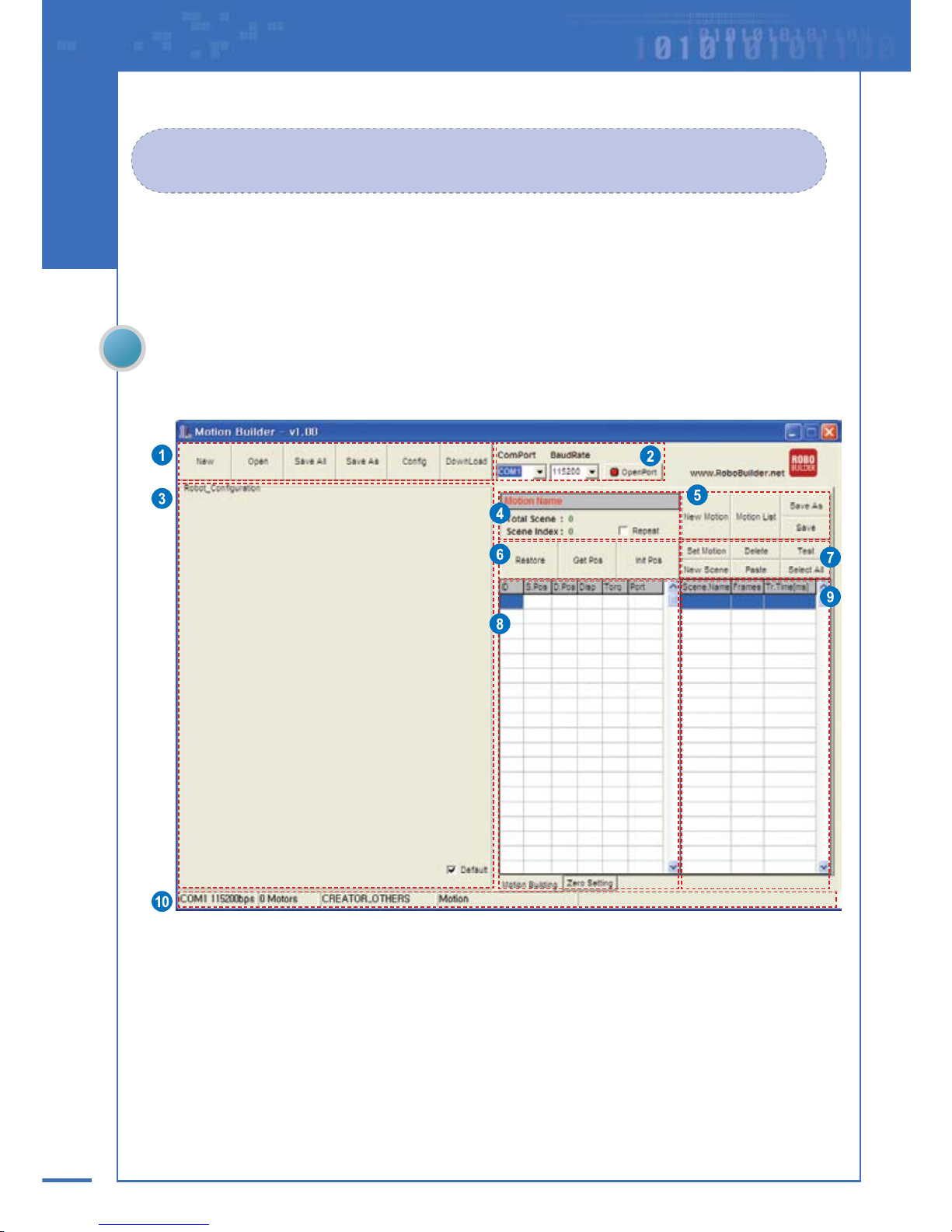
MotionBuilder
The MotionBuilder screen layout is as below.
Page 68

69
Chapter 3. Operating RoboBuilder
No. Area Name Functions & Descriptions
①
Menu Bar
ㆍ New: creates a new project by defining project name, file path, robot type etc.
ㆍOpen: opens an existing project file. (*.prj)
ㆍSave All: stores the running project file and all data related to the project.
ㆍSave As: saves the running project file as a different name.
ㆍConfig: configures and sets the wCK module.
ㆍDownload: transfers robot files to control box.
②
PC Port
connection
ㆍComPort: sets the port on PC to connect RoboBuilder with.
ㆍBaudRate: sets the data communication speed. (default: 115,200kbps)
ㆍOpenPort: opens the set PC port to connect RoboBuilder with.
③
Robot
Configuration
ㆍ This area illustrates the mechanical construction of the wCK modules. Using the jog
dial pad, you can control the movement of each wCK module.
* If the [Default] button is not checked, you can freely relocate the jog dial pads of the wCK mod-
ules by dragging them with your mouse(right-click).
When [Default] is selected, they return to their original default position.
④
Motion File
Information
ㆍMotion Name: displays the name of the motion file running.
ㆍTotal Scene:
displays the total number of scenes that constitutes the motion file running.
ㆍScene Index: displays the number of the selected scene in the running motion file.
ㆍRepeat: is used to repeat and test the selected one or more scenes.
⑤
Motion File
Management
ㆍNew Motion: creates a new motion file.
ㆍMotion List: add, open, modify, or remove motion files.
ㆍSave As: saves the running motion file as a different name.
ㆍSave: saves the running motion file.
⑥
Position Control
ㆍRestore: sets all modules’ displacement angles of the selected scene to “0”.
ㆍGet Pos: captures the desired posture of a robot after adjusting the posture manually
with user’s hands. Captured posture is saved as in a scene.
ㆍInit Pos: sets the initial torque and angle of the selected wCK module.
⑦
Scene
Management
ㆍSet Motion: sets the name and saved path of the motion file, configures PID gains of
wCK modules.
ㆍDelete: deletes the selected scene.
ㆍTest: run the selected scene.(multiple scene selection available)
ㆍNew Scene: adds a new scene.
ㆍPaste: pastes the copied scene in the selected position.
ㆍSelect All: selects all scenes in a motion file.
⑧
wCK module
Control Detail
ㆍID: displays the ID number of the wCK module.
ㆍS.Pos: stands for Start Position and it displays the start position of the wCK module in
unit of control angle.
ㆍD.Pos: stands for Destination Position and it displays the destination position of the
wCK module in unit of control angle.
ㆍDisp: stands for Displacement and it displays the control angle difference between
S.Pos and D.Pos.
ㆍTorq: It displays the speed of the wCK module.(0: Very fast, -4: Very slow)
ㆍPort: displays the status of the LED installed on the I/O port of the wCK module.
⑨
Scene Editing
ㆍScene Name: displays the scene name.
ㆍFrames: displays the number of frames, into which a scene is divided.
ㆍTr.Time[ms]:
displays the transition time that is used for operating the corresponding scene.
⑩
Task Info
ㆍ displays the task related information such as the PC port connected, communication
speed, number of wCK modules connected, robot type, etc.
Page 69

70
RBC Upgrade Tool
The screen layout of the RBC Upgrade Tool is as below.
No. Area Name Descriptions
①
Connection It selects the port connected between PC and RoboBuilder and the transfer speed
②
File Selection
It selects the firmware file to upgrade.
Click [Click here and Push Button] for upgrade.
(Press the Reset button that is located between PF1 and PF2 LEDs on the control box)
③
Upgrade It displays the upgrade status of the status display line.
④
Exit It ends the firmware upgrade program.
Page 70

71
Chapter 3. Operating RoboBuilder
Connecting RoboBuilder with PC
RoboBuilder robot connects to a PC via an RS232 serial cable. First check the PC’s com port
number assignment and connect the RS232 cable to the RoboBuilder.
The appropriate platform type(HUNO, DINO, DOGY) should be set on the control box (use PF1 or
PF2 button) as instructed on page 72.
Checking PC serial Port
01 Right-click [My Computer] icon on Desktop
and select the [property(R)] button.
Check the com port number assigned to the port into which the RS232 communication cable will be
plugged.
02 Select the [Hardware] tab in the
[System Registration Information] window
and click [Device Manager].
03 Select [Port] in the [Device Manager]
window and check the serial port number
assigned from PC.(COM1, COM2, etc.)
When the PC has no serial port, separately
purchase and use a USB to Serial converter
to connect RoboBuilder with PC.(refrain from
using a converter of poor quality)
Connecting the Serial Cable
After checking the port assigned from PC, plug the
RS232 cable that is provided in the product package
to connect the RoboBuilder and PC.
Page 71

72
Setting Robot Platform
Appropriate platform type(HUNO, DINO, DOGY) should be set on the control box before connecting
RoboBuilder with a PC. For example, it your robot is a HUNO but control box is set as DOGY platform,
the robot won’t operate properly. Robobuilder will think the robot is in the form of the configured
platform. Below is how to set and check the correct robot platform type on control box.
In case your robot is a non-standard platform(other than HUNO, DINO, and DOGY), press PF2 button
for 3 seconds until PF2 LED turns on orange.
HUNO - PF1 turns on blue LED
DINO - PF1 turns on pink LED
DOGY - PF1 turns on red LED
Press PF1 button
for 3 seconds
Press PF1 button
for 3 seconds
Press PF1 button
for 3 seconds
Non-standard platform - PF2 turns on orange LED
Page 72

73
Chapter 3. Operating RoboBuilder
Operating Control Box
By manipulating the control box, you can turn on the robot, select the platform type as well as
change to different modes such as PC control mode, battery recharge mode, firmware upgrade mode.
Function Manipulation Descriptions
Power ON Turn on the power switch.
It performs self-test(LEDs sequentially turns on and
off) and set as the most recently used platform.
ㆍHUNO: PF1 LED turns blue
ㆍDINO: PF1 LED turns pink
ㆍDOGY: PF1 LED turns red
ㆍNon-standard mode: PF2 LED turns orange
Power OFF Turn off the power switch. All LEDs turned off.
Power Status LED display
Different Power LED indicates different status of
battery charge level.
ㆍPOWER LED Green: Battery charge is sufficient
ㆍPOWER LED Red: Battery charge insufficient
ㆍPOWER LED Red turns on and off:
Immediate charge required
ㆍPOWER LED Green turns on and off:
In Charging mode
Home Posture
Turn on the power with PF1 button pressed
and release the button after 2 seconds.
Robot slowly takes the home posture.
(Only applicable for HUNO)
PC Control
Mode
Turn on the power with PF2 button pressed
and release the button after 2 seconds.
The control box is changed to PC control mode.
ㆍPF1 LED: Blue LED turns off
ㆍPF2 LED: Orange LED turns off
Platform
Setting
Press PF1 or PF2 button for 3 seconds.
Each time PF1 button pressed for 3 seconds, the
platform is changed in sequence
(HUNO ⇒ DINO ⇒ DOGY)
ㆍHUNO: PF1 LED turns blue
ㆍDINO: PF1 LED turns pink
ㆍDOGY: PF1 LED turns red
* When PF2 button is pressed for 3 seconds, it is changed
to non-standard platform. (Orange LED turns on)
Remote
Controller
Registration
Turn on the power switch with both PF1 and
PF2 buttons pressed and release the buttons
after 2 seconds. When the blue Run LED
blinks, use remote control and press the red
button (
) in the middle towards robot.
Press the red button(
) of the remote control
within 10 seconds for successful registration.
If registration is successfully completed, all LEDs of
control box blink together three times and the robot
turns into standby mode.
* When firmware of control box is upgraded, user should
register the remote controller again.
Power Switch
PF1 Button
(Standard platform)
PF2 Button
(Non-standard platform)
Reset Button
Page 73

74
Using Remote Control
The best way to use the remote control is to have remote controller point to the top of robot’s head.
Because the IR sensor unit is installed inside the top cover of head.
Whenever a robot is turned on, press red button in the middle to have your robot take basic posture
before playing with other buttons. Otherwise the buttons won’t work properly.
(This is a setting to prevent users from being injured by robot’s unexpected sudden action)
Button Motion Button Motion
Perform motion number 1
Perform motion number 11
Perform motion number 2
Perform motion number 12
Perform motion number 3
Perform motion number 13
Perform motion number 4
Perform motion number 14
Perform motion number 5
Perform motion number 15
Perform motion number 6
Perform motion number 16
Perform motion number 7
Perform motion number 17
Perform motion number 8
Perform motion number 18
Perform motion number 9
Perform motion number 19
Perform motion number 10
Perform motion number 20
ㆍ Do not use the remote control under a strong fluorescent lamp light. The IR sensor unit inside the top cover of head
may be affected by the fluorescent light.
ㆍ Maximum 5 remote controls can be registered to one control box, which means 5 different users can control a robot
together. If a user registers a 6th remote control, the 1st remote control information is deleted, so the control box only
remembers the most recently registered 5 remote controls.
Stand Up A
Stand Up B
Move Forward
Left Turn
Right Rurn
Side Step to the left
Side Step to the right
Arm Attack to the left
Arm Attack to the right
Move Backward
Basic Posture.
Buttons for downloaded
motions
Buttons for Basic Motions
Buttons for User
Defined Motions
(press a numeric button with
button pressed)
Page 74

75
Chapter 3. Operating RoboBuilder
Programming
Before starting programming, turn on your PC, run the MotionBuilder program, and then connect
RoboBuilder with your PC through the PC cable. Set RoboBuilder to “PC Control Mode” before it
is connected with PC. If you are planning on programming for long time connect the
power adapter too.
A motion file is what defines the RoboBuilder’s movements(file extension is .rbm).
If RoboBuilder can display a motion, then this motion file is played in the control box. A project file
includes more than one motion file and is used to manage multiple motion files efficiently. A motion file
consists of more than one scene.
ㆍProject file: It consists of multiple motion files that are created or edited by a user.
ㆍMotion file: It consists of multiple scenes and executes a complete motion.
ㆍScene: It is a smaller motion unit that constitutes a complete motion file, which contains the information such as
frames, Tr. Time, movement of wCK modules, LED lighting, etc.
ㆍFrame: It is a smaller motion unit that constitutes a scene.
The greater the number of frames, the smoother the robot’s motion will tend to be.
Page 75

76
Creating New Robot File(example, HUNO)
02 Select [New] on the menu bar. In the [New Project] window, assign project name, select the
location to save the project file, and robot platform type. Then click [OK].
03 new project for HUNO is created and HUNO image shows up and the basic information of the
wCK modules appear on the [Robot Configuration] area.
01 Set ComPort and BaudRate, and click OpenPort( ). If the connection between PC and
RoboBuilder is normal, the button changed to ClosePort(
).
Do not be surprised because the robot
can move suddenly at this moment.
Page 76

77
Chapter 3. Operating RoboBuilder
04 Select [New Motion] to add a new motion file into the project. Select the motion file name
and save path etc, and click [OK]
06 The new scene is now registered and the total scene is changed to “1.”
05 Register the first scene in the created motion file. Set the name of the scene, the number of
frames, and Tr.Time, and click [OK].
Tr.Time/Frame = 20~50 recommended,
Do not set this value less than 20.
Page 77

78
No. Name Description
①
ID It displays the ID number of the wCK module.
②
S.Pos It displays the start position of the wCK module as in control angle.
③
D.Pos It displays the destination position of the wCK module as in control angle.
④
Disp It displays the displacement between D.Pos and S.Pos as in control angle.
⑤
To rq It displays the motion speed of the wCK module.
⑥
Port
It displays the LED status of the wCK module.
(only available for transparent wCK module)
⑦
Scene.Name It displays the name of the scene.
⑧
Frames It displays the number of frames.
⑨
Tr.Time[ms] It displays the transition time of the corresponding scene. (Unit: ms)
The control angle 1 means the physical angle 1.05° (degree).
07 When you press [Test] button, the robot moves to the destination position of the selected scene
and the [Test] button get changed to [Return] button. In this state, set the posture of the robot
by adjusting the angles of wCK modules. You can drag the red point in the jog buttons for wCK
modules on the [Robot Configuration] area.
When you adjust the angle by using the red point on the wCK module jog button, slowly rotate the red
point because a sudden movement of robot may cause the robot to fall or an injury to user.
The angle setting is available within the
range of the minimum and maximum
value stored in the [Config] menu.
Page 78

79
Chapter 3. Operating RoboBuilder
08 When the desired posture with required destination positions are set, click [Return].
The changed settings are saved in the scene and the [Return] button is changed back to [Test].
If a scene is clicked, the robot moves to start position of the corresponding scene.
If you click on a scene click [Test], the robot shows the motion saved in the scene by moving to the destination
position. More than one scene can be selected and tested by dragging multiple scenes. If the [Repeat] check box
is selected in the Motion File Information area, the robot repeatedly performs the selected scenes.
For more precise control of the wCK module angle when setting the destination
position, the user can follow the three different methods instructed below:
1. Adjusting by changing D.Pos value
① Select the scene to change and click [Test].
② When the button is changed to [Return],
double-click the D.Pos value of the wCK module to change.
③ Type in the numeric D.Pos value and press ENTER.
④ Click [Return] to save the changed value.
2. Adjusting by changing Disp value
① Select the scene to change and click [Test].
② When the button is changed to [Return],
double-click the Disp value of the wCK module to change.
③ Type in the numeric Disp value and press ENTER.
④ Click [Return] to save the changed value.
3. Teaching Method(Posture Capture using [Get Pos] button)
Refer to P84 for details about Motion-Teaching method
① Select the scene to change and click [Test].
② When the button is changed to [Return], click [Get Pos].
③ Select the wCK modules to adjust and click [Close].
④ Now the selected wCK modules are in Teaching Mode so manually
adjust posture of the robot using hands.
⑤ Click [Capture].
⑥ Click [Return] to save the changed settings.
Page 79

80
10 Select added scene, click [Test] (it is changed to [Return] button), and adjust the posture for the
destination position.
11 When programming is completed, click [Save All] to save the project and motion file information.
09 Click [New Scene] to add another scene. Give the new scene a name, the required number
of frames, and the Tr.time. Then click [OK]. A new scene is added.
Repeat the process of adding scenes as shown above until you finish a complete motion file.
Page 80

81
Chapter 3. Operating RoboBuilder
Modifying Robot File(example, HUNO)
To modify an existing motion file, follow the instructions below:
01 Set ComPort and BaudRate, and click OpenPort( ). If the connection between PC and
RoboBuilder is normal, the button changed to ClosePort(
).
02 Select [Open] on the menu bar. Select the desired project in the [Open Project] window and
click [Open]. (e.g. HunoBasic.prj)
03 The settings of the wCK modules appear in the [Robot Configuration] window. At the same time,
the first motion file that is saved in the project opens.
In case of HunoBasic.prj, the
HunoBasic_PunchLeft motion opens.
In order to modify a motion file that
you downloaded from Internet, add the
motion file to a desired project first.
Page 81

82
04 Open [Motion List] menu. Choose a motion file to modify and click [Open to Edit].
The selected file opens.
05 When the scene to modify is selected, the robot moves to the start position of the corresponding
scene and the wCK module angle appears in the [Robot Configuration] window. Detailed control
information is shown on the [wCK Module Control Detail] area in the middle of the screen.
06 When the selected scene is double-clicked, the detail information of the scene will appear
in a pop-up window. Change the scene name, number of frames, and Tr.Time if needed.
Page 82

83
Chapter 3. Operating RoboBuilder
07 To change a scene, select the scene and click [Test]. The robot moves to destination position and
stops. Use the jog buttons of wCK modules in the [Robot Configuration] area to adjust the angles
of required wCK modules. When the angle adjustment is completed, click [Return] to save the
change.
08 When the required scene modification is completed, click [Save All] to save the project
and motion file.
For more precise control of the wCK module angle when setting destination
position, user can follow the three different methods instructed below:
1. Adjusting by changing D.Pos value
① Select the scene to change and click [Test].
② When the button is changed to [Return], double-click the D.Pos value
of the wCK module to change.
③ Type in the numeric D.Pos value and press ENTER.
④ Click [Return] to save the changed value.
2. Adjusting by changing Disp value
① Select the scene to change and click [Test].
② When the button is changed to [Return], double-click the Disp value
of the wCK module to change.
③ Type in the numeric Disp value and press ENTER.
④ Click [Return] to save the changed value.
3. Teaching Method(Posture Capture using [Get Pos] button)
① Select the scene to change and click [Test].
② When the button is changed to [Return], click [Get Pos].
③ Select the wCK modules to adjust and click [Close].
④ Now the selected wCK modules are in Teaching Mode so manually
adjust posture of the robot using hands.
⑤ Click [Capture].
⑥ Click [Return] to save the changed settings.
Refer to P84 for details about Motion-Teaching method
Page 83

84
Quick & Easy Motion-Teaching Programming Method
What is the Motion-Teaching Programming Method?
The motion-Teaching Programming Method is a quick & easy way of creating robot’s motions.
When editing a scene, click the [Get Pos] button in the middle of screen and use your hands to
adjust the angles of desired wCK modules freely.
The captured posture is saved as the destination position of the selected scene.
The destination position is automatically saved as the start position of the next scene.
01 Select a scene to edit and click [Test].
Robot moves to destination position of the scene and the [Test] button is changed to [Return].
02 Click [Get Pos] in the middle of screen.
A wCK module selection window appears and the button is changed to [Capture].
You can either add a new scene or select an existing scene.
Page 84

85
Chapter 3. Operating RoboBuilder
06 Click [Return] to save the change and close.
07 If the adjusted posture is not perfect, repeat the step 01 to 06.
03 Check the desired IDs of wCK modules to be adjusted and click [Close].
If you touch and handle the wCK modules with your hands, you can feel the selected modules
are now free of Torque and freely movable.
Now the selected wCK modules are in “Teaching Mode”. The unselected wCK modules are powered with torque
and difficult to rotate, which is set to help the robot stand still.
05 When finished with manual posture adjusting, click [Capture] to load in the change.
The [Capture] button returns to [Get Pos] buttion.
04 Use your hands to freely adjust the desired posture of the robot.
Be careful not to forcefully rotate the unselected wCK modules.
Page 85

86
Modifying Downloaded Robot File
The following section explains how to modify robot files that a user has downloaded from the Internet.
01 Set ComPort and BaudRate, and click OpenPort( ). If the connection between PC and
RoboBuilder is normal, the button changed to ClosePort(
).
02 Select [Open] on the menu bar. Select the desired project in the [Open Project] window and
click [Open]. (e.g. HunoBasic.prj)
Page 86

87
Chapter 3. Operating RoboBuilder
03 Choose [Motion List] menu and click [Add to Project] to select the file that you downloaded
from Internet and saved in your hard disk.
Click [Open to Edit] button to open the motion file.
04 Follow the steps of 05~08 of [Modifying Existing Robot File] section in page 82~83.
Page 87

88
Transferring Robot File to Control Box
You should first transfer and save robot files to control box before playing the robot using remote
control. Any robot file that you created with Motion Builder or downloaded from the Internet can be
used. The file transfer is done as per the instructions below.
01 Set ComPort and BaudRate, and click OpenPort( ). If the connection between PC and
RoboBuilder is normal, the button changed to ClosePort(
).
02 Click [Download] on the menu bar.
Select the robot file to transfer to control box, and click [Open].
Page 88
89
Chapter 3. Operating RoboBuilder
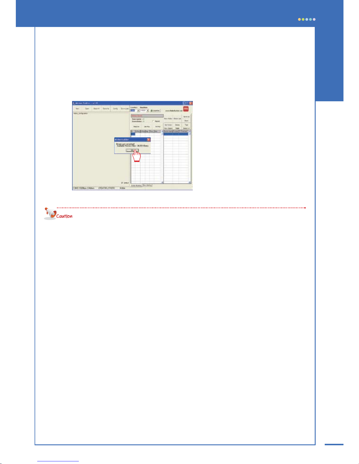
03 The selected [motion file] is transferred to control box. When download completed, success
message appears. Click [OK] to finish.
Repeat step 02 and step 03 until you transfer all required files.
· Once file transfer starts, all robot files already existing in control box are deleted and new files saved from
the beginning. So the first file transferred is assigned to button 1 of remote control, the second file transferred is
assigned to button 2, and the third file to buttion 3 and so on. So you have to plan and decide which robot
file to be assigned to which button of remote control before you actually start the file transfer.
· If the size of a certain robot file is too large, the control box may not be able to save up to 20 files.
· The motion performed with MotionBuilder can be a little bit different from the motion actually performed with
the transferred motion file.
Page 89

90
Playing with Robot
When building and programming are completed, you can play the RoboBuilder and have it play
the motions saved in control box by using remote control.
01 Turn on the control box and press the basic posture button ( ) on the remote control.
(Unless the basic posture button is pressed, other buttons do not work.)
02 According to platform type, the Robot takes its basic posture.
03 Perform motions by pressing the basic motion buttons or user defined motion buttons on
the remote control.
04 RoboBuilder performs best when the robot is located on a flat, horizontal, and hard floor.
A robot may lose balance, fall down, or show an awkward movement on a floor which is
uneven, or made from rough material such as carpet, rug etc.
05 The basic motions of the standard platform robots(HUNO,DINO,DOGY) are available and
playable immediately after building is completed. Use the buttons for basic motions.
For more information on the remote control, refer to the “Using Remote Control” section on page 74.
Page 90

91
Chapter 3. Operating RoboBuilder
Recharging Battery
To charge the battery enclosed in the control box, connect the adapter to the control box as shown
in below picture and turn on the power to prepare for charging.
The battery charging takes one and a half hour and automatically stops when finished.
Press the
button and button
on the remote control at the same time.
When charging begins, the green LED starts blinking.
Blinking stops when charging finished.
· If you choose to press PF1 and PF2 buttons on the control box, make sure the two buttons are pressed
simultaneously. Otherwise robot may execute another function.
·When shipped from the factory the battery pack are not charged.
So please use power adapter to operate the robot the first time.
·The enclosed power supply is used not only for recharging the battery but also for supplying direct power to the robot.
So it can be used as an alternative to the battery and be used to operate the robot continuously
(This function is not supported when recharging battery).
How to Start Battery Charging
Press the PF1 button and PF2
button at the same time for more
than 3 seconds.
Or
· If battery is fully charged, the robot can operate continuously approximately for 10 minutes to 30 minutes.
The operation time varies depending on the characteristics of a robot file, i.e. the types of motions performed.
·If you leave the controller on for long time with power on, it may cause a failure or a damage to battery.
·When you recharge the battery more than twice consecutively, it may cause a failure or a damage to
the battery.
Page 91

92
Replacing Battery
The battery replacement procedure is as follows:
01 Remove the four bolts from the cover of control box.
02 Replace the batteries after disconnecting the connector.(Battery Type: 8.4V Ni-MH)
03 Close the cover of the control box and screw in the four bolts.
Page 92

93
Chapter 3. Operating RoboBuilder
Setting Home Posture
In case of HUNO, if RoboBuilder’s motion is unstable or abnormal, you can choose to adjust the
Home Posture. For example, if robot’s movement is different from what it is supposed to be and it
doesn’t move as the way the robot file defines, you can correct the problem by adjusting the Home
Posture. The Home Posture adjustment is done as follows:
Using the Package Tray
You can adjust the home posture by using the plastic tray provided with the product package.
01 Prepare fully assembled HUNO and tray.
02 Run MotionBuilder software and connect RoboBuilder with PC using PC cable.
Set Com port and BaudRate and click OpenPort(
). If the connection between PC
and RoboBuilder is normal, the button will change to ClosePort(
).
When the connection is ready, select the [ZERO Setting] tab.
RS232 Cable
Page 93

94
04 Click [Open] on the menu bar to open a HUNO project. Any HUNO project will work.
05 Click [ZeroCaptureReady] and use hands to make sure that HUNO is correctly inserted into
the tray. The front HUNO should be tightly touching the hollow surface of tray.
03 Lay down HUNO into the tray as shown in the picture.
Turn on the control box as in PC Control Mode.
Page 94

95
Chapter 3. Operating RoboBuilder
Make sure that HUNO is laid down tightly into the tray by pressing some points of robot’s back side.
Follow the sequence as shown below.
① Press position 1( ) vertically together by using thumbs and index fingers of two hands.
② Use one hand to vertically press position 4(
) and use the other hand to press position 2( ).
③ Press position 3( ) vertically with two hands.
④ Repeat step② to press position 4( ) and position 2( ) together.
Correct Home Posture can be secured only when the front of the robot is tightly attached to the hollow surface
of tray.
06 If robot is laid correctly, click [ZeroCapture]. The current posture is copied in as one of the
five sampling postures and pop-up windows appears saying “4 times left”. Click [OK].
Page 95

96
07 Pull out HUNO from tray and release wCK modules.
Follow step 05 and 06 to complete the required 5 of posture captures.
When the adjustment is completed, a pop-up window appears saying “Complete!”. Click [OK].
08 Click [Save Zero & Set to RBC] to save the home posture and apply it to control box.
click [OK].
09 Remove HUNO from the tray and click [ZeroPose] to check if new home posture is correctly
configured or not.
Page 96

97
Chapter 3. Operating RoboBuilder
Adjusting Home Posture Manually
Without using the tray, you can also adjust robot’s home posture manually.
01 Run MotionBuilder software and connect RoboBuilder with PC using PC cable.
Set Com port and BaudRate and click OpenPort(
). If the connection between PC
and RoboBuilder is normal, the button will change to ClosePort(
).
When connection is ready, select the [ZERO Setting] tab.
02 Click [Open] on the menu bar to open a HUNO project. Any HUNO project will work.
RS232 Cable
Page 97

98
03 When you click [ZeroControlReady], the screen is changed to a mode where you can manually
adjust the home posture.
04 Adjust the home posture by using the jog buttons of wCK modules in the
[Robot Configuration] area.
Page 98

99
Chapter 3. Operating RoboBuilder
05 When adjustment is completed, click [StopZeroControl].
06 Click [Save Zero & Set to RBC] to save the home posture and apply it to control box.
Page 99

100
Manipulating Home Posture File
This button fetches the zero point file saved in control box.
This button applies the changed
home posture values to control box.
This button makes the robot take the
corresponding home posture.
This button saves a copy the home
posture file as a different name.
This button loads up any home posture
file separately saved elsewhere.
Page 100

101
Chapter 3. Operating RoboBuilder
Upgrading Firmware
The procedure to upgrade control box with up-to-date firmware is as follows.
01 Run “RBC Upgrade Tool” software and turn on the control box.
02 Connect control box with PC using RS-232 cable. Set Com Port and Baud Rate.
03 Select the firmware file to use for upgrade by clicking the folder icon.
click [Open] when firmware hex file is selected.
04 Click [Click here and Push Button] to enter “upgrade ready state”.
 Loading...