

Page 1
Mode d’emploi et installation
FR
Hotte de Cuisine
Instructions for use and installation
GB
Cooker Hood
Bedienungsanleitung und Einrichtung
DE
Dunstabzugshaube
Istruzioni per l’uso e l’installazione
IT
Cappa
Instrucciones de instalacion e utilizacion
E
Campana
Instructies voor het gebruik en installeren
NL
Dampkap
Inspiration 770
Page 2
F SOMMAIRE
GB CONTENTS
RACCORDEMENT ÉLECTRIQUE
CONSEILS D’INSTALLATIONS
POSE DE L’APPAREIL
FONCTIONNEMENT
CONSEILS D’UTILISATIONS
ENTRETIEN
GARANTIE ET SERVICE APRÈS-VENTE
REMARQUES
D INHALT
NETZANSCHLUSS
MONTAGEHILFEN
MONTAGE DES GERÄTES
BETRIEB DES GERÄTES
NUTZUNG
WARTUNG UND REINIGUNG
GARANTIE UND KUNDENDIENST
WICHTIGE HINVEISE
ELECTRICAL WIRING
INSTALLATION ADVICE
FITTING THE APPLIANCE
OPERATION
USEFUL HINTS
MAINTENANCE
GUARANTEE AND AFTER-SALES-SERVICES
REMARKS
I CONTENUTI
COLLEGAMENTO ELETTRICO
CONSIGLI DI INSTALLAZIONE
POSA DELL’ APPARECCHIO
FUNZIONAMENTO
CONSIGLI DI UTILIZZO
MANUTENZIONE
GARANZIA ED ASSISTENZA TECNICA
NOTE
E SUMARIO
CONEXION ELECTRICA
CONSEJOS DE INSTALACION
INSTALACION DEL APARATO
FUNCIONAMIENTO
CONSEJOS DE UTILIZACION
MANTENIMIENTO
GARANTIA Y ASSISTENCIA TECNICA
NOTA
NL INHOUD
ELECTRISCHE BEDRADING
MONTAGE AANWIJZING
AANSLUITEN VAN HET APPARAAT
FUNKTIONEREN
GEBRUIKSADVIES
ONDERHOUD
AFTER SALES SERVICE
OPMERKINGEN
Page 3
F
Nous vous remercions de la conance que vous nous avez accordée en choisissant un appareil de la
gamme ROBLIN.
Celui-ci a fait l’objet de toute notre attention dans sa conception et sa réalisation.
An qu’il vous donne entière satisfaction, nous vous recommandons de lire avec attention cette notice qui
vous expliquera comment l’installer, l’utiliser et l’entretenir dans les meilleures conditions.
La présente notice d’emploi vaut pour plusieurs versions de l’appareil. Elle peut contenir des descriptions
d’accessoires ne gurant pas dans votre appareil.
Avec ce kit, il est possible d’installer à distance le moteur de la hotte à l’intérieur de l’habitation. L’installation
devra être effectuée par un personnel qualié en accord avec les directives réglementaires édictées par les
services compétents en matière de renouvellement d’air. Le fabricant ne pourra être tenu pour responsable
des dégâts résultant d’une installation incorrecte ou de sa non-conformité.
1 RACCORDEMENT ÉLECTRIQUE.
• La hotte est équipée d’un cordon d’alimentation de type HO5VVF 3 x 0,75 mm² comportant une
che normalisée 10/16 A avec système de mise à la terre.
Mode de protection : classe I. Tension d’alimentation : 220-240 V mono - 50Hz / 220 V - 60Hz.
Vérier que la tension du secteur est identique aux valeurs indiquées sur la plaque signalétique à
l’intérieur de la hotte
• Si la hotte est raccordée directement sur le réseau sans sa che, un interrupteur omnipolaire avec
une ouverture de contact de 3 mm doit être installé avant la hotte. Le l de terre (Jaune / vert) ne doit
pas être interrompu par cet interrupteur.
2 CONSEILS D’INSTALLATION.
• Pour un fonctionnement idéal, nous vous conseillons une plage de hauteur de pose qui se situe de
0,65 m à 0,70 m au-dessus du plan de cuisson. Toutefois, il est formellement interdit d’installer toute
hotte ou groupe d’aspiration à une distance inférieure à 0,65 m du plan de travail (risque d’inammation
des ltres). La fumée doit monter naturellement vers la zone de captation.
• Respecter le diamètre de sortie de l’appareil : la hotte ne doit en aucun cas être raccordée à un
conduit de ventilation mécanique contrôlée (V.M.C.).
• Lorsqu’on évacue l’air vicié dans un conduit d’évacuation, veiller à ce que celui-ci ne soit pas déjà
exploité à véhiculer des gaz ou fumées provenant d’appareils alimentés par une énergie autre qu’électrique.
• Positionner le plan de cuisson au plus près de l’évacuation et éviter la formation de coudes sur la
gaine, an de réduire au maximum les pertes de charges.
• Dans tous les cas d’installation, veiller au bon renouvellement d’air de la cuisine. Penser à effectuer une ou des entrées d’air par une grille de section égale ou supérieure au diamètre du tuyau
d’évacuation, an de ne pas mettre la cuisine en dépression.
• Prévoir une aération sufsante lorsqu’un appareil de cuisson ou autre utilise simultanément l’air
ambiant de la pièce où est installée la hotte.
• La dépression maximum crée dans la pièce doit être inférieur à 0.04 mbar, ce qui évite un retour de
gaz de combustion.
• L’appareil doit être positionné de telle façon que la che d’alimentation soit accessible.
• Cet appareil ne doit pas être utilisé par des personnes (y compris les enfants) ayant des capacités
1
Page 4
F
psychiques, sensorielles ou mentales réduites, ni par des personnes n’ayant pas l’expérience et la
connaissance de ce type d’appareils, à moins d’être sous le contrôle et la formation de personnes responsables de leur sécurité.
Les enfants doivent être surveillés pour s’assurer qu’ils ne jouent pas avec l’appareil.
3 POSE DE L’APPAREIL.
Montage et raccordement doivent être réalisés par un installateur* qualié.
(*) Le non-respect de cette condition entraîne la suppression de la garantie du constructeur et
tout recours en cas d’accident.
Attention: prendre bien soin d’employer les chevilles adaptées au support, se renseigner au près
des fabricants, effectuer un scellement si nécessaire. La société décline toute responsabilité en
cas d’accrochage défectueux dû au perçage et chevillage au plafond.
Une isolation thermique adéquate devra être prévue au cas où le moteur serait installé dans une
pièce particulièrement froide pour éviter tout problème de condensation.
• La Hotte peut être installée directement sur la surface inférieure des Armoires Murales (650 mm min.
depuis le Plan de Cuisson)
• Réaliser une ouverture pour l’emboîtage sur la surface inférieure de l’Armoire Murale, comme indiqué .
• Percer le dessus du meuble haut ou le fond pour l’évacuation.
• Fixer les 2 équerres à l’aide des vis fournies.
• Mettre en place le clapet anti-retour (Rep. 9) sur la sortie de l’appareil. Fixer l’ensemble à l’aide de
colliers ou de ruban adhésif appropriés.
•Emboîter l’appareil dans la découpe et le xer sur les 2 équerres à l’aide des 4 vis fournies.
• RACCORDEMENTS
- VERSION EVACUATION EXTERIEURE
Brancher la hotte à la tuyauterie de sortie via un tuyau rigide ou exible de ø 150 mm, au choix de l’installateur.
• Fixer le tuyau par des colliers appropriés. Le matériau nécessaire n’est pas fourni.
• Retirer l’ éventuel ltre anti-odeur au charbon actif.
- VERSION RECYCLAGE
L’air ltré est évacué dans la pièce à travers une ouverture placée sur la partie supérieure du meuble ou
de la hotte.
• Percer un trou de ø 155 mm. sur l’éventuelle tablette qui se trouve au-dessus de la hotte.
• Connecter la asque au trou de sortie sur la tablette qui se trouve au-dessus de la hotte, au moyen
d’un tuyau rigide ou exible de ø150 mm.
• Fixer le tuyau par des colliers appropriés. Le matériau nécessaire n’est pas fourni.
• placer la cartouche à charbon actif dans son logement.
• Insérer l’appareil dans la découpe et le xer à l’aide des vis fournies sur les équerres.
2
Page 5
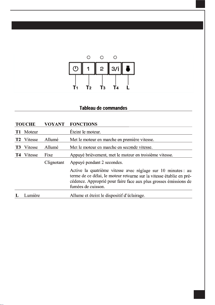
4 FONCTIONNEMENT
F
3
Page 6
F
5 CONSEILS D’UTILISATION.
• Pour obtenir une efcacité maximum d’absorption des fumées ou des vapeurs, faire fonctionner
l’appareil 5 minutes environ avant et après la cuisson des aliments; La première vitesse est conseillée
pour les cuissons à feu doux et pour les sauces. La deuxième pour les cuissons soutenues, grillades et
friteuses. La troisième est indiquée pour les cuissons à forte émanation de graisses et vapeur.
• IMPORTANT . NE JAMAIS FLAMBER DE METS AU DESSOUS DE L’APPAREIL
Ne laissez jamais de ammes libres sous la hotte en fonctionnement.
• Les fritures nécessitent une surveillance permanente, l’huile surchauffée pouvant s’enammer.
6 ENTRETIEN.
Déconnecter le câble d’alimentation pour toute intervention électrique.
L’appareil a été conçu pour faciliter au maximum les opérations d’entretien, synonyme de bon fonction-
nement et rendement de l’appareil dans le temps.
• Nettoyage des ltres métalliques.
Il est indispensable de procéder à un NETTOYAGE PÉRIODIQUE de ces ltres à la main (avec un déter-
gent liquide à l’eau tiède et rinçage) ou au lave- vaisselle (tous les deux mois environ pour une utilisation
normale).
• Carrosserie.
Nettoyer régulièrement celle-ci en utilisant des produits détergents, non abrasifs et une éponge légèrement
humide. N’utilisez jamais d’éponges ou de chiffons trempés
N’introduisez aucun objet, ni les mains dans l’ouverture servant à l’évacuation de l’air
• Conduit d’évacuation.
Vérier tous les 6 mois le bon écoulement de l’air vicié.
Observer les prescriptions réglementaires locales concernant l’évacuation de l’air vicié.
• Éclairage.
Avant toute intervention sur l’appareil, mettre l’interrupteur d’allumage des lampes en position éteinte.
Ne pas dépasser la puissance prescrite et ne pas changer de type de lampe.
• Télécommande.
Attention, la télécommande doit être équipée de piles alcalines standards : LR003-AAA, 1.5V.
Ces piles devraient assurer un usage optimum de longue durée et doivent être positionnées
correc-tement, elles peuvent exploser si elles sont endommagées ou exposées à la chaleur. Ne
pas les jeter dans le feu. An de préserver l’environnement, merci de déposer ces piles dans un
conteneur approprié.
7 GARANTIE ET SERVICE APRÈS-VENTE.
• En cas d’anomalie de fonctionnement, prévenez votre installateur qui devra vérier l’appareil et son
raccordement.
• Dans le cas où un composant électrique viendrait à être endommagé, celui-ci ne peut être remplacé
que par un atelier de réparation reconnu par le fabricant, car des outils spéciaux sont nécessaires.
• Débrancher complètement l’appareil.
• Exigez toujours l’utilisation de pièces de rechange d’origine. La non observation de cette prescription
peut compromettre la sécurité de l’appareil.
• Lors de la commande de pièces détachées, rappeler le numéro de l’appareil inscrit sur la plaque
signalétique située à l’intérieur de la hotte.
• Seule la facture d’achat de l’appareil fera foi pour l’application de la garantie contractuelle.
Cette garantie ne couvre pas les consommables comme :
4
Page 7
- L’éclairage : lampes incandescentes, halogènes ...
- Les ltres.
8 REMARQUES.
Cet équipement est conforme à la norme européenne sur la basse tension 2006/95/CE relative à la
sécurité électrique et aux normes européennes: 2004/108/CE relative à la compatibilité électromagnétique
et 93/68 relative au marquage CE.
F
Lorsque ce symbole
produit est couvert par la Directive Européenne 2002/96/EC. Votre produit est conçu et fabriqué avec
des matériaux et des composants de haute qualité, qui peuvent être recyclés et utilisés de nouveau.
Veuillez vous informer du système local de séparation des déchets électriques et électroniques. Veuillez
agir selon les règles locales et ne pas jeter vos produits usagés avec les déchets domestiques usuels.
Jeter correctement votre produit usagé aidera à prévenir les conséquences négatives potentielles contre
l’environnement et la santé humaine.
d’une poubelle à roue barrée est attaché à un produit, cela signie que le
5
Page 8
GB
Thank you for buying a ROBLIN product which has been manufactured to the highest quality standards
to meet your requirements.
We recommend you carefully read this booklet in which you will nd instructions for installation, hints for
use and maintenance.
The Instructions for Use apply to several versions of this appliance. Accordingly, you may nd descriptions of individual features that do not apply to your specic appliance.
With this kit it is possible to place the blower of the kitchen hood to a remote position inside the house.
Installation of the kit must be carried out by qualied staff, following all the rules given by the relevant
authorities concerning the exhaust air ducting. The manufacturer will not be liable for any damages
resulting from incorrect or from improper installation.
1 ELECTRICAL
• This cooker hood is tted with a 3-core mains cable with a standard 10/16A earthed plug.
• Alternatively the hood can be connected to the mains supply via a double-pole switch having 3mm
minimum contact gap on each pole.
• Before connecting to the mains supply ensure that the mains voltage corresponds to the voltage on
the rating plate inside the cooker hood.
• Technical Specication: Voltage 220-240 V, single phase ~ 50 Hz / 220 V - 60Hz.
2 INSTALLATION ADVICE
• Ensure the cooker hood is tted in compliance with the recommended xing heights.
• To ensure the safe operation of this cooker hood, we recommend that the hood should not be tted
below 65cm (for electric) or (70cm for gas) the measurements taken from the surface of the cooking
appliance to the underside of the cooker hood.
• It is a possible re risk if the hood is not sited as recommended.
• To ensure the best results, the cooking fumes should be able to rise naturally towards the inlet grilles
on the underside of the cooker hood and the cooker hood should be positioned away from doors and
windows, which will create turbulence.
• Ducting
• If the room where the hood is to be used contains a fuel-burning appliance such as a central heating
boiler then its ue must be of the room sealed or balanced ue type.
• If other types of ue or appliances are tted ensure that there is an adequate supply of fresh air to
the room. Ensure the kitchen is tted with an airbrick, which should have a cross-sectional measurement
equivalent to the diameter of the ducting being tted, if not larger.
• The ducting system for this cooker hood must not be connected to any existing ventilation system,
which is being used for any other purposes or to a mechanically controlled ventilation ducting.
• The ducting used must be made from re retardant materials and the correct diameter must be used,
as incorrect sized ducting will affect the performance of this cooker hood.
• When the cooker hood is used in conjunction with other appliances supplied with energy other than
electricity, the negative pressure in the room must not exceed 0.04 mbar to prevent the fumes from
combustion being drawn back into the room.
• The appliance is for domestic use only and should not be operated by children or people who are
inrm without supervision.
• This appliance must be positioned so that the wall socket is accessible.
• This appliance is not intended for use by persons (including children) with reduced physical, sensory
or mental capabilities, or lack of experience and knowledge, unless they have been given supervision or
instruction concerning use of the appliance by a person responsible for their safety.
Children should be supervised to ensure that they do not play with the appliance.
3 FITTING
Any permanent electrical installation must comply with the latest regulations concerning this type of installation and a qualied electrician must carry out the work. Non-compliance could cause serious accidents
6
Page 9
GB
or injury and would deem the manufacturers guarantee null and void.
IMPORTANT - The wires in this mains lead are coloured in accordance with the following code :
green / yellow : earth blue : neutral brown : live
As the colours of the wires in the mains lead of this appliance may not correspond with the coloured
markings identifying the terminals in your plug, proceed as follows.
- The wire which is coloured green and yellow must be connected to the terminal in the plug which is
marked with the letter E or by the earth symbol
- The wire which is coloured blue must be connected to the terminal which is marked with the letter N
or coloured black.
- The wire which is coloured brown must be connected to the terminal which is marked with the letter
L or coloured red.
ATTENTION: Do not forget to use adequate plugs to the support brackets. Enquire after the manufacturers. Do an embedding if necessary. The manufacturer accepts no responsibility in case of a
faulty hanging due to the drilling and the setting up of plugs in the ceiling.
It is necessary to provide an adequate thermal isolation in case the blower is placed in particularly
cold rooms.
• The Hood can be tted onto the lower surface of the wall furniture. (650 mm min. from the surface of the
cooking appliance to the underside of the cooker hood.)
• To carry out a cutting (embedding) on the lower surface of the wall furniture, as indicated.
• To drill the outlet onto the top or the back of the wall furniture.
• To x the 2 squares using the provided screws.
• To place the anti-backowats item 9 over the round outlet. To secure the connections with appropriate
clamping rings or adhesive tape.
or coloured green or green and yellow.
• To place the hood into the embedding and t it on the 2 squares using the 4 screws supplied.
• DUCTING
The hood is more effective when used in the extraction mode (ducted to the outside). When the cooker
hood is ducted to the outside, charcoal lters are not required.
The ducting used must be 150 mm (6 INS), rigid circular pipe and must be manufactured from re retardant material, produced to BS.476 or DIN 4102-B1. Wherever possible utilise rigid circular pipe which has
a smooth interior, rather than the expanding concertina type ducting.
Maximum length of ducting run:
- 4 metres with 1 x 90° bend.
- 3 metres with 2 x 90° bends.
- 2 metres with 3 x 90° bends.
The above assumes our 150 mm (6 INS) ducting is being installed. Please note ducting components and
ducting kits are optional accessories and have to be ordered, they are not automatically supplied with the
chimney hood.
- In the extraction mode:
• To connect the round outlet of the hood via a rigid or exible duct of ø 150 mm.
• To secure the connections with appropriate clamping rings or adhesive tape not provided.
• To remove the possible charcoal lte.
- In the recirculation mode: The ltered air is evacuated in kitchen through an outlet placed on the top of
furniture or the hood.
• To drill a hole of ø 155 mm on the top of furniture.
• To connect the round outlet of the hood via a rigid or exible duct of ø 150 mm to the outlet on the top of
7
Page 10
GB
the furniture.
• To secure the connections with appropriate clamping rings or adhesive tape not provided.
• To Install the charcoal lters inside the canopy.
• The hood can be connected to the mains supply via a double-pole switch having 3mm minimum contact
gap on each pole.
8
Page 11
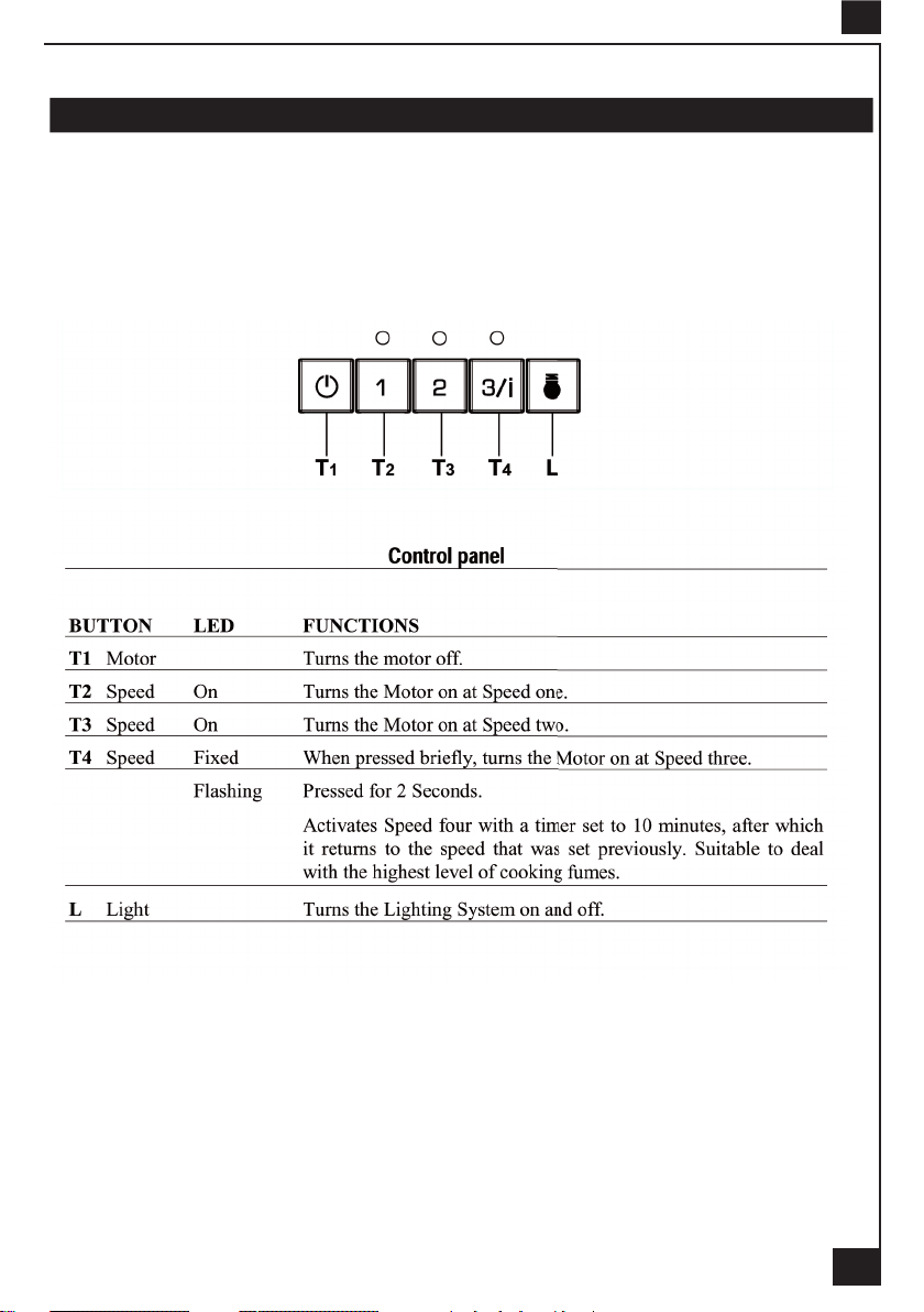
4 OPERATION
GB
9
Page 12
GB
5 USEFUL HINTS
• To obtain the best performance we recommend you to switch ‘ON’ the cooker hood a few minutes (in
the boost setting) before you start cooking and you should leave it running for approximately 15 minutes
after nishing.
• IMPORTANT: NEVER DO FLAMBÉ COOKING UNDER THIS COOKER HOOD
• Do not leave frying pans unattended during use as over-heated fat and oil might catch re.
• Do not leave naked ames under this cooker hood.
• Switch ‘OFF’ the electric and gas before removing pots and pans.
• Ensure heating areas on your hotplate are covered with pots and pans when using the hotplate
and cooker hood simultaneously.
6 MAINTENANCE
Before carrying out any maintenance or cleaning isolate the cooker hood from the mains supply.
The cooker hood must be kept clean; a build up of fat or grease may cause a re hazard.
Casing
• Wipe the cooker hood frequently with a clean cloth, which has been immersed in warm water containing a mild detergent and wrung out.
• Never use excessive amounts of water when cleaning particularly around the control panel.
• Never use scouring pads or abrasive cleaners.
• Always wear protective gloves when cleaning the cooker hood.
Metal Grease Filters : The metal grease lters absorb grease and dust during cooking in order to keep
clean the cooker hood inside. The grease lters should be cleaned once a month or more frequently if
the hood is used for more than 3 hours per day.
To remove and replace the metal grease lters
• Remove the metal grease lters one at a time by releasing the catches on the lters; the lters can
now be removed.
• The metal grease lters should be washed, by hand, in mild soapy water or in a dishwasher.
• Allow to dry before replacing.
Active Charcoal Filter : The charcoal lter cannot be cleaned. The lter should be replaced at least
every three months or more frequently if the hood is used for more than three hours per day.
To remove and replace the lter
• Remove the metal grease lters.
• Press against the two retaining clips, which hold the charcoal lter in place and this will allow the lter
to drop down and be removed.
• Clean the surrounding area and metal grease lters as directed above.
• Insert the replacement lter and ensure the two retaining clips are correctly located.
• Replace the metal grease lters.
Extraction tube : Check every 6 months that the dirty air is being extracted correctly. Comply with local
rules and regulations with regard to the extraction of ventilated air.
Lighting : If the lamp fails to function check to ensure it is tted correctly into the holder. If lamp failure
has occurred then it should be replaced with identical replacement.
Do not replace with any other type of lamp and do not t a lamp with a higher rating.
Remote control handset : Caution, the remote control handset must be tted with standard LR03-AAA
size 1.5V zinc-carbon alkaline batteries. These batteries should give a long life and constant discharge
throughout their life. These batteries must be disposed of properly and could explode if damaged or
exposed to heat. Do not dispose of on re. Dispose of batteries in the appropriate sort
10
Page 13
GB
7 GUARANTEE AND AFTER SALES SERVICE
• In the event of any malfunction or anomaly, notify your tter who will have to check the appliance and its connection.
• In the event of damage to the mains supply cable, this can only be replaced by at approved repair
centre appointed by the manufacturer who will have the required tools and equipment to carry out any
repairs properly. Repairs carried out by other persons will invalidate the guarantee.
• Use only genuine spare parts. Should these warnings fail to be observed it could affect the safety of
your cooker hood.
• When ordering spare parts quote the model number and serial number written on the rating plate,
which is found on the casing behind the grease lters inside the hood.
• Proof of purchase will be required when requesting service. Therefore, please have your receipt
available when requesting service as this constitutes the date from which your guarantee commenced.
This Guarantee does not cover :
- Damage or calls resulting from transportation, improper use or neglect, the replacement of any light
bulbs or lters or removable parts of glass or plastic.
These items are considered to be consumable under the terms of this guarantee.
8 REMARKS
This appliance complies with European regulations on low voltages Directive 2006/95/CE on electrical
safety, and with the following European regulations: Directive 2004/108/CE on electromagnetic compatibility and Directive 93/68 on EC marking.
When this crossed-out wheeled bin symbol
ered by the European directive 2002/96/EC.Your product is designed and manufactured with high quality
materials and components, which can be recycled and reused.Please inform yourself about the local
separate collection system for electrical and electronic product. Please act according to your local rules
and do not dispose of your old products with your normal household waste. The correct disposal of your
old product will help prevent potential negative consequences for the environment and human health.
is attached to a product it means the product is cov-
11
Page 14
D
Wir gratulieren Ihnen für das Vertrauen, welches Sie uns mit dem Kauf dieses ROBLIN-Produktes
entgegengebracht haben.
Dieses Gerät wurde nach dem neuesten Stand der Technik entwickelt und mit grösster Sorgfalt hergestellt.
Um eine problemlose und sichere Montage zu ermöglichen und die volle Zufriedenheit bei der Benutzung
dieser Dunstesse zu erhalten, empfehlen wir Ihnen dringenst, sowohl die Montageanweisung sorgfältig
zu beachten und die Gebrauchs-und Wartungshinweise aufmerksam zu lesen und anzuwenden. Bitte
bewahren Sie diese Broschüre sorgfältig auf.
Diese Gebrauchsanleitung gilt für mehrere Geräte-Ausführungen. Es ist möglich, dass einzelne Ausstattungsmerkmale beschrieben sind, die nicht auf Ihr Gerät zutreffen.
Es ist möglich mit diesem Set, den Motor endfern von der Haube in der Wohnung unterzubringen. Die Einrichtung wird von einem Qualifizierten Installateur gemacht, im Einverständnis mit
den ordnungsgemäßen verfügten Direktiven im Gebiet Luft-Erneuerung. In falls einer falsche
Einrichtung oder einer Schlechte Benützung wird den Fabrikant nicht Verantwortlich sein.
1 NETZANSCHLUSS
• Die Dunstabzugshaube ist mit einer Anschlussleitung der Art HO5VVF 3 x 0,75 mm2, die
einen Schutzstecker 10 / 16 A enthält, ausgestattet. Das entspricht Schutzklasse 1.
Nennspannung : 220 - 240 V - Wechselstrom : 50 Hz / 220 V - 60 Hz.
• Es ist sicherzustellen, daß die Netzspannung den angegebenen Anschlusswerten auf dem
Typenschild im Inneren der Dunstesse entspricht.
• Beim Anschluss der Dunstesse an das Wechselstromnetz ist ein zweipoliger Schalter mit
einem Öffnungsweg von wenigstens 3 mm für jeden Pol zwischenzuschalten.
2 MONTAGEHILFEN
• Die Mindest- und Höchstabstände zwischen der Dunstesse und der Kochäche sind zu
berücksichtigen. Wir empfehlen Ihnen einen Abstand von 650 mm bis 700 mm zwischen Filteräche
und Oberkante Kochäche einzuhalten, um einen optimalen Betrieb des Gerätes zu gewährleisten.
Jedoch ist es untersagt, Dunstessen oder Einbaugeräte mit einem Abstand, der niedriger als
650 mm ist, einzubauen (Entzündungsgefahr der Filter). Beachten Sie die richtige Ableitung der
Kochschwaden (Luftzug kann Turbulenzen verursachen).
• Der Aussendurchmesser am Gebläseabgang des Gerätes ist für die Wahl des AbluftRohrsystems zu berücksichtigen : Die Dunstesse darf keinesfalls an eine Entlüftungsleitung mit
Unterdruck angeschlossen werden. Die Abluft darf nicht in einen Schornstein geleitet werden, der
für die Abgase von Koch- oder Heizgeräten, (Kohle-, Öl-, oder Gas-Öfen / -Herde) benutzt wird.
• Die Kochstelle (und damit auch die Dunstesse) unbedingt so planen und installieren, daß
möglichst kurze Wege für eventuelle Abluft-Rohrleitungen erreicht werden. So wenig Umlenkungen
[90°-Bögen] wie möglich vorsehen ! Keine Querschnittsverengungen vornehmen !
• Für eine ausreichende Belüftung zur Gewährleistung des Luftaustausches in der Küche
ist zu sorgen. Nötigenfalls ist an einer Aussenwand eine entsprechende Öffnung anzubringen,
die die Frischluftzufuhr gewährleistet.
• Sorgen Sie für eine ausreichende Zuluft, wenn z.B. ein gasbetriebenes Koch-oder anderes Gerät die Luft des Raumes, in dem die Dunstesse eingebaut ist, gleichzeitig verwendet. Ein
gefahrloser Betrieb ist möglich, wenn bei gleichzeitigem Betrieb von Dunstesse und Feuerstätte
im Raum ein Unterdruck von höchstens 0.04 mbar erreicht wird und ein Rücksaugen der Feuerstättenabgase vermieden wird.
Das Gerät muß so installiert werden, daß der Geräte-Stecker leicht erreichbar ist.
• Dieses Gerät darf nicht von Personen, auch Kindern, mit verminderten psychischen,
sensorischen und geistigern Fähigkeiten, oder von Personen ohne Erfahrung und Kenntnisse
benutzt werden, sofern sie nicht von für ihre Sicherheit verantwortlichen Personen beaufsichtigt
und beim Gebrauch des Geräts angeleitet werden.
Kinder dürfen sich nicht unbeaufsichtigt in der Nähe des Geräts aufhalten und auf keinen Fall
12
Page 15
mit dem Gerät spielen.
3 MONTAGE DES GERÄTES
Montage und Anschluss müssen von einem qualizierten Installateur* durchgeführt werden.
(*) Wenn diese Bedingung nicht eingehalten wird, wird die Garantie des Herstellers, sowie jeder
Anspruch im Falle eines Unfalles aufgehoben.
Achtung ! Bitte beachten Sie bei der Montage das Gewicht der kompletten Dunstesse. Die Tragfähigkeit der Decke oder alternativ der Trägerplatte für diese Zugbelastung muss vor der Montage
geprüft und gegebenenfalls durch die Anbringung von geeigneten Befestigungs-oder Stabilisierungselementen hergestellt werden. Kann eine hinreichende Tragfähigkeit nicht sichergestellt
werden, ist von einer Montage abzusehen.
Im Falls das Motor in einen sehr kaltes Zimmer angebracht sein sollte, muss einen angemessene
Isolation vorgesehen sein um Probleme wegen der Kondensation zu vermeiden.
MONTAGE
• Bohren der Trägerplatte und Montage der Dunstabzugshaube
• Die Haube kann direkt an der Unterseite der Hängeschränke (mindesten 650 mm von der Kochmulde
entfernt) xiert werden.
• An der Unterseite des Hängeschranks, wie in der Abbildung gezeigt, eine Öffnung anbringen.
• In das über oder der hintere Teil der Haube vorhandene Bord ein Loch bohren.
D
• Die 2 Winkeln mit den gelieferten Schrauben xieren.
• Der Haube im Zerschneiden einfügen und es auf den 2 Winkeln mittels der 4 gelieferten Schrauben
festlegen.
• Die Rückstauklappe (Pos .9) am Gerätsausgang anbringen. Beim Anschluss die Ringe und den passenden Kleber benutzen.
• ANSCHLÜSSE
- ANSCHLUSS IN ABLUFTVERSION
• Für die Installation in Abluftversion, die Haube mit Hilfe eines Rohres oder Schlauches von 150 mm
Durmesser an die Auslassleitung anschließen.
• Das Rohr mit geeigneten Rohrschellen xieren. Das Hierzu erforderliche Material wird nicht mitgeliefert.
• Eventuell vorhanden Aktivkohlelter entnehmen.
- ANSCHLUSS IN UMLUFTVERSION
Die ltrierte Luft wird durch einer Öffnung im Zimmer weg-befördert.
• In das über der Haube vorhandenen Bord ein Loch Ø 155 mm bohren.
• Den Flansch beim Luftaustritt am Bord oberhalb der Haube mittels Rohr oder Schlauch Ø 150 mm
anschließen.
• Das Rohr mit geeigneten Rohrschellen xieren. Das Hierzu erforderliche Material wird nicht mitgeliefert.
• Die Aktivkohlenltern, mit Hilfe der 2 x 4 Spangen, auf den Metalllter xieren.
• Die Haube einschieben und mit den Schrauben auf den Winkeln xieren.
13
Page 16

D
4 BETRIEB DES GERÄTES
14
Page 17

5 NUTZUNG
• Um ein optimales Absaugen der Dunstschwaden zu erzielen, wird empfohlen, das Gerät
vor dem Kochen einzuschalten und nach dem Kochen noch einige Zeit nachlaufen zu lassen. Für
die Speisen, die wenig Dunst entwickeln, verwenden Sie vorzugsweise eine niedere Geschwindigkeit.
• WICHTIG : NIEMALS UNTER DEM GERÄT FLAMBIEREN.
Niemals eine grosse Koch-Flamme bei eingeschalteter Dunstesse unbedeckt lassen.
Wenn der Topf entfernt wird, ist die Koch-Flamme abzuschalten oder für einen kurzen Zeitraum
auf kleinste Stellung zu drehen, dennoch aber unbedingt im Auge zu behalten.
Frittiergeräte, die unter der Dunstesse betrieben werden, sind während der gesamtem Betriebsdauer zu beaufsichtigen: Überhitztes Öl kann sich entzünden und die Haube in Brand setzen.
6 WARTUNG UND REINIGUNG
Vor jedem Eingriff im Gerät immer den Netzstecker ziehen, oder die Sicherung herausdrehen bzw. die
Stromzufuhr unterbrechen.
Bei der Entwicklung des Gerätes wurde besonders die Wartungsfreundlichkeit berücksichtigt.
• Herausnehmen des Metalllters :
D
Es ist unerlässlich, diese Filter REGELMÄSSIG falls notwendig auch in kurzen Intervallen, mit der Hand
(lauwarmes Wasser mit Waschmittel und Nachspülen) oder in der Geschirrspülmaschine zu REINIGEN.
Diese Massnahmen vermindern die Brandgefahr (starke Fettrückstände sind leicht brennbar).
• Gehäuse:
Keine nassen Tücher für die Reinigung der Oberächen der Dunstesse verwenden. Es sollen nur milde
Reinigungsmittel und leicht feuchte Tücher verwendet werden. Keine Gegenstände in die Luftaustrittsöffnung stecken. Nicht in die Luftaustrittsöffnung greifen.
• Abluftleitung:
Kontrollieren Sie von Zeit zu Zeit, dasss der Luftkanal nicht verstopft ist. Diese Prüfung muss halbjährlich
durchgeführt werden. Die behördlichen Anforderungen, für die Ableitung der Abluft sind zu berücksichtigen.
• Beleuchtung:
Bei Leuchtmittel-Wechsel in jedem Fall den Schalter der Beleuchtung ausschalten.
Die Art des Leuchtmittels nicht wechseln. Leistung nicht überschreiten.
• Fernbedienung:
Vorsicht ! Die Fernbedienung muss mit Zink-Kohle Alkali-Batterien im Standard-Format LR03AAA zu 1.5 V, angezeigt ausstatten sein. Die Batterie müssten eine dauerhaft optimale Benutzung
garantieren. Diese Batterie müssen richtig einstecken sein, und mögen zerspringen, wenn sie beschädigt
sind oder in der Hitze liegen. Nicht ins Feuer werfen ! Um die Umwelt zu schützen, bitte diese Batterien
15
Page 18

D
in einen geeigneten Container abladen.
7 GARANTIE UND KUNDENDIENST
• Bei Ausfall des Gerätes benachrichtigen Sie Ihren Händler, der den Werkskundendienst informieren wird.
• Stets nur Original-Ersatzteile verwenden.
• Wird dies nicht berücksichtigt, kann die Sicherheit des Gerätes beeinträchtigt werden. Außerdem
erlischt die Garantie.
• Bei der Bestellung von Ersatzteilen geben Sie bitte Nummer und Typ des Gerätes, die Sie auf
dem Typenschild nden, das sich im Gehäuse hinter den Fettltern bendet, an.
• Für die Anwendung der vertraglichen Garantie wird nur die Rechnung des Gerätes verbindlich
anerkannt. Von der Garantieleistung ausgenommen sind:
- Die Beleuchtung : Klassik - und Halogenbeleuchtung
- Die Filter (Filter sind als Verbrauchsgüter anzusehen).
8 WICHTIGE HINWEISE
Dieses Gerät entspricht den europäischen Niederspannungsrichtlinien 2006/95/EWG zur elektrischen
Sicherheit, den europäischen Richtlinien 2004108/EWG zur elektromagnetischen Verträglichkeit und den
Richtlinien 93/68/EWG zur CE Kennzeichnung.
Das Symbol
als normaler Haushaltsabfall zu behandeln ist, sondern an einem Sammelpunkt für das Recycling von
elektrischen oder elektronischen Geräten abgegeben werden muss. Durch Ihren Beitrag zum korrekten
Entsorgen dieses Produktes schützen Sie die Umwelt und die Gesundheit Ihrer Mitmenschen. Umwelt
und Gesundheit werden durch falsches Entsorgen gefährdet. Weitere Informationen über das Recycling
dieses Produktes erhalten Sie von Ihrer kommunalen Behörde, den örtlichen Müllentsorgungsunternehmen oder von Ihrem Fachhändler.
auf dem Produkt oder seiner Verpackung weist darauf hin, dass dieses Produkt nicht
16
Page 19

La ringraziamo per la ducia accordataci nell’aver scelto un prodotto della gamma ROBLIN.
Questo apparecchio è stato studiato e realizzato con la massima cura, secondo i più alti criteri di
qualità.
Le raccomandiamo di leggere attentamente questo opuscolo, nel quale troverà le istruzioni per
installare, utilizzare e conservare al meglio il suo apparecchio ed ottenere dal suo acquisto il massimo
dei beneci.
Questo libretto di istruzioni per l’uso è previsto per più versioni dell’ apparec-chio. É possibile che siano
descritti singoli particolari della dotazione, che non riguardano il Vostro apparecchio.
Questo kit permette lo spostamento dell’aspiratore della cappa in un punto remoto all’interno dell’abitazione.
L’installazione deve essere effettuata da personale specializzato, rispettando tutte le prescrizioni delle
autorità competenti relative allo scarico dell’aria da evacuare. Il produttore declina qualsiasi responsabilità
per danni dovuti ad installazione non corretta o non conforme alle regole dell’arte.
1 COLLEGAMENTO ELETTRICO
• La cappa é dotata di un cavo di alimentazione di tipo HOSVVF 3x 0,75 mm² e comporta una
spina normalizzata 10/16 A, con sistema di terra .
Protezione : classe 1. Tensione di alimentazione : 220 - 240 V mono - 50 Hz / 220 V - 60 Hz.
Vericare che la tensione di rete sia identica ai valori indicati sull’etichetta all’interno della cappa.
• Se la cappa é collegata direttamente all’impianto elettrico senza la sua spina, è necessario istallare
prima della cappa un interruttore omnipolare con un’apertura di contatto di 3 mm. senza interrompere
illo della terra (giallo/verde).
2 CONSIGLI DI INSTALLAZIONE
• Per un funzionamento ideale, vi consigliamo un’altezza di posa situata entro 0,65 m e 0,70 m al
di sopra del piano di cottura. Tuttavia, é formalmente vietata l’istallazione di qualsiasi cappa o gruppo
aspirante ad una distanza inferiore a 0,65 m dal piano di cottura (rischio di incendio dei ltri). I fumi devono
salire naturalmente verso la zona aspirante (attenzione alla correnti d’aria che potrebbero provocare delle
turbolenze).
• Rispettare il diametro di uscita dell’apparecchio : la cappa non deve in alcun caso essere collegata
ad un condotto di ventilazione meccanica controllata (V.M.C.).
• Qualora l’aria viziata fosse scaricata in un condotto d’evacuazione, vericare che quest’ultimo non
sia già utilizzato per evacuare gas o fumi provenienti da apparecchi alimentati da un’energia diversa da
quella elettrica.
• Posizionare il piano di cottura in corrispondenza della zona di evacuazione della cappa ed evitare
la posa di gomiti che ne potrebbero ridurre la potenza.
• In tutti i casi di istallazione, fare attenzione al ricambio d’aria della cucina. Istallare una o più griglie
d’aerazione di misura uguale o superiore al diametro del tubo di evacuazione per evitare di mettere il
locale in depressione.
• Prevedere un’aerazione sufficiente qualora un apparecchio di cottura o altro utilizzi
simultaneamente l’aria dell’ambiente in cui é situata la cappa. La depressione massima creata nel locale
deve essere inferiore a 0,04 mbar per evitare un ritorno di gas di combustione.
• L’apparecchio deve essere posizionato in modo che la spina sia accessibile.
• Questo apparecchio non deve essere utilizzato da persone (bambini inclusi) con ridotte capacità
psichiche, sensoriali o mentali, oppure da persone senza esperienza e conoscenza, a meno che non
siano controllati o istruiti all’uso dell’apparecchio da persone responsabili della loro sicurezza.
I bambini devono essere supervisionati per assicurarsi che non giochino con l’apparecchio.
I
3 POSA DELL’ APPARECCHIO
Il montaggio ed il collegamento devono essere realizzati da un istallatore qualicato*
17
Page 20

I
(*) Il non rispetto di questa condizione provocherà l’annullamento della garanzia del costruttore
e di qualsiasi ricorso i caso di incidente.
Attenzione: usare dei tasselli adatti al supporto, informarsi presso i fabbricanti, effettuare una
sigillatura se necessario. La società declina ogni responsabilità in caso di agganciatura difettosa
dovuta alla perforazione ed al ssaggio al softto.
Nel caso in cui l’aspiratore venga collocato in ambienti molto freddi prevedere un adeguato
isolamento termico.
• La cappa puo’ essere installata direttamente sul lato inferiore dei mobili da parete (ad una distanza
minima di 650 mm. dal piano di cottura)
• Praticare un’apertura per l’incastro nella facciata inferiore del mobile da parete come indicato.
• Svitare le tre viti situate vicino alle lampade. Togliere il gruppo luci per accedere ai ssaggi del pannello
di aggiustamento.
• Forare la parte superiore o la parte posteriore del mobile.
• Fissare i due supporti con le viti fornite.
• Inserire la cappa nel taglio e ssarla sui 2 quadrati per mezzo delle 4 viti fornite.
• Posizionare la valvola di non-ritorno (Rif. 9) sull’uscita dell’apparecchio. Fissare il tutto tramitecollari o
nastro adesivo adeguati.
COLLEGAMENTO
VERSIONE EVACUAZIONE ESTERNA :
• Per un collegamento in versione evacuazione esterna, collegare la cappa alle tubazioni di scrico tramite
un tubo rigido o essibile di Ø 150 mm.
• Fissare il tubo tramite collari appropriati. Il materiale necesario non è fornito.
• Togliere gli eventuali ltri al carbone attivo.
VERSIONE FILTRANTE :
• L’aria ltrata viene evacuata nel locale attraverso un’apertura situata nella parte superiore del mobile o
della cappa.
• Praticare un’apertura di Ø 155 mm. sul lato superiore del mobile.
• Collegare la angia al foro di uscita del mobile tramite un tubo rigido o essibile di Ø 150 mm.
• Fissare il tubo tramite collari appropriati. Il materiale necssario non è fornito.
• Fissare i ltri al carbone attivo sui ltri metallici con i 2 x 4 fermagli.
• Collegare la cappa interponendo un interruttore bipolare con apertura dei contatti di almeno 3 mm.
• Inserire l’apprecchio nell’apertura del mobile e ssarlo ai supporti con le viti fornite.
18
Page 21

4 FUNZIONAMENTO
I
19
Page 22

I
5 CONSIGLI DI UTILIZZO
• Per ottenere il massimo dell’efcacia per quanto riguarda l’assorbimento dei fumi o del vapore,
mettere in funzione l’apparecchio prima e dopo la cottura degli alimenti ; per le preparazioni che producono
poco vapore, utilizzare di preferenza le velocità più basse.
• IMPORTANTE : NON CUCINARE MAI PIATTI ALLA FIAMMA SOTTO LA CAPPA.
Non lasciate mai amme libere sotto una cappa funzionante. Spegnere la amma o ridurla al minimo per
un tempo ridotto e sotto sorveglianza.
• Se cucinate delle fritture, abbiate cura di farlo con attenzione costante : l’olio surriscaldato
potrebbe inammarsi.
6 MANUTENZIONE
Staccare il cavo di alimentazione prima di qualsiasi intervento elettrico.
L’apparecchio é stato pensato per facilitare al massimo le operazioni di manutenzione, sinonimo di buon
funzionamento e rendimento nel tempo.
• Pulizia dei ltri metallici.
E’ necessario procedere ad una PULIZIA PERIODICA dei ltri a mano (con un detergente liquido diluito
in acqua tiepida e risciacquo) oppure in lavastoviglie , con una frequenza che dipenderà dall’utilizzo, per
evitare i rischi di incendio.
• Struttura esterna.
Pulire regolarmente la parte esterna utilizzando dei detergenti non abrasivi ed una spugna leggeremente
umida. Non utilizzare mai spugne o panni bagnati.
Non introdurre alcun oggetto e tanto meno le mani nell’apertura d’evacuazione dell’aria.
• Condotto d’evacuazione.
Vericare ogni 6 mesi la buona evacuazione dell’aria viziata.
Rispettare le norme nazionali vigenti relative all’evacuazione dell’aria viziata.
• Illuminazione.
Prima di effettuare qualsiasi intervento sull’apparecchio, mettere l’interruttore di accensione delle lampade
in posizione spenta.
Non superare la potenza prescritta e non cambiare tipo di lampada.
• telecomando.
Questo apparecchio può essere comandato elettronicamente attraverso un telecomando. È importante
utilizzare per il telecomando pile alcaline zinco-carbone da 1.5V del tipo standard LR03-AAA. Queste pile
garantiscono lunga durata ed una curva di scarica costante durante tutto il tempo di vita, mantenendo
costanti le prestazioni del telecomando no alla scarica completa . Non riporre il telecomando in prossimità
di fonti di calore.Non disperdere le pile nell’ambiente, depositarle negli appositi contenitori.
7 GARANZIA ED ASSISTENZA TECNICA
• In caso di anomalia di funzionamento, avvisare il vostro istallatore il quale dovrà vericare
l’apparecchio ed il suo collegamento. Nel caso in cui il cavo fosse danneggiato, dovrà essere sostituito
esclusivamente da un centro di riparazione consigliato dal fabbricante, poiché la riparazione prevede
l’utilizzo di attrezzature apposite.
• Staccare la spina dell’apparecchio.
• Esigete sempre l’utilizzo di pezzi di ricambio originali in quanto il non rispetto di questa prescrizione
potrebbe compromettere la sicurezza dell’apparecchio e metterebbe ne al contratto di garanzia.
• Per ordinare i pezzi di ricambio, indicare il numero dell’apparecchio che si trova sull’etichetta
segnaletica.
• Solo la fattura d’acquisto farà fede ai ni dell’applicazione della garanzia contrattuale.
20
Page 23

Questa garanzia non copre: - L’illuminazione : lampade ad incandescenza, alogene.
- I ltri.
In quanto sono considerati come materiali di consumo.
8 NOTE
Quest’apparecchio é conforme alla norma europea sulla bassa tensione 2006/95/CE relativaalla sicurezza
elettrica e alle norme europee: 2004/108/CE relativa alla compatibilità elettromagnetica e C.E.E. 93/68
relativa alla marcatura CE.
I
Quando ad un prodotto è attaccato il simbolo
signica che il prodotto è tutelato dalla Directiva Europea 2003/96/EC. Questo prodotto è stato progettato
e fabbricato con materiali e componenti di alta qualità, che posssono esere riciclati e riutilizzati.Si prega di
informarsi in merito al sistema locale di raccolta differenziata per i prodotti elettrici ed elettronici.Rispettare
le norme locali in vigore e non smaltire i prodotti vecchi nei normali riuti domestici. Il correto smaltimento
del prodotto aiuta ad evitare possibili conseguenze negative per la salute dell’ambiente e dell’uomo.
del bidone con le ruote segnato da una croce,
21
Page 24

E
Le agradecemos la conancia que nos participan ustedes elegiendo un aparato de la gama ROBLIN
quien fue el objeto de toda nuestra atención en su concepción y realisación.
Para que les de entera satisfacción, les aconsejamos ustedes leer con atención esta noticia que les
explicara ustedes como instalarle, utilisarle y mantenerle en las mejores condiciones.
Esta noticia de instrucciones esta utilizada para varios aparatos. Puede contener descripciones de
accessorios no utilizados en su proprio aparato.
Con este kit, es possible instalar a distancia el motor de la campana al interior de la habitacion. La
instalacion debe ser realisada por un personal calicado en acuerdo con las directivas reglamentarias
decretadas por los servicios competentes conciernando el cambio del aire. El fabricante no puede ser
responsable de los danos resultantes de la no conformidad o de una instalacion incorrecta.
1 CONEXION ELECTRICA
• La campana esta dotada de un cable de alimentación del tipo HOSVVF 3x 0,75 mm² y permite un
cable de conexión normalizada 10/16 A con conexión a tierra..
Protección : clase 2. Tensión de alimentación : 220-240 V mono - 50 Hz / 220 v - 60 Hz.
Vericar que la tensión de la red sea idéntica a los valores indicados en la etiqueta que se encuentra
dentro de la campana.
• Si la campana esta conectada directamente a la instalación eléctrica sin su cable de conexión, será
necesario instalar antes que la campana, un interruptor omnipolar con una abertura de contacto de 3
mm. sin interrumpir la toma a tierra (amarillo/verde).
2 CONSEJOS DE INSTALACION
• Para un perfecto funcionamiento, es aconsejable una distancia de instalación entre 0,65 m y 0,70
m de la base de la campana al plano de cocción. Con todo esto, esta formalmente prohibida la
instalación de cualquier campana o grupo de aspiración a una distancia inferior a 0,65 m del plano de
cocción ( entonces existiría riesgo de incendio del ltro). Los humos deben salir libremente por la zona
de aspiración (atención a la corriente de aire, la cual puede provocar turbulencias).
• Respetar el diámetro de salida del aparato : la campana no debe en ningún caso ser instalada a un
conducto de ventilación mecánica controlada (V.M.C.).
• En caso de que el aire viciado fuese conducido por un conducto de evacuación, hay que vericar
que dicho conducto no corresponda a tuberías de evacuación de humos causados por combustión.
• Colocar el plano de cocción teniendo en cuenta la zona de evacuación de la campana, y evitar la
instalación de ángulos que podrían reducir la potencia de la misma.
• En cualquier instalación hay que prestar atención al recambio del aire de la cocina. Instalar uno o
mas rejillas de aireación de medida igual o superior al diámetro del tubo de evacuación para evitar
depresiones en la habitación.
• Si en la cocina se usan tanto la campana como otros aparatos no accionados con energía eléctrica (por ejemplo aparatos a gas), se debera proceder a una ventilación suciente del ambiente. La
depresión máxima creada en la habitación debe ser inferior a 0,04 mbar para evitar un retorno del gas
de combustión.
• El aparato debe estar colocado de tal forma que el cable de conexión sea accesible.
• Este aparato no debe ser utilizado por personas (asi como las niños) cuyas capacitades psíquicas,
sensoriales o mentales estan reducidas, ni por personas que no tienen la experiencia o el conocimiento
de este tipo de aparatos a menos de estar bajo el control y la formación de personas responsables de
ella securidad.
Las niños deben ser cuidados para asegurarse que no juegan con el aparato.
3 INSTALACION DEL APARATO
La instalación y conexión debe ser realizada por un instalador autorizado *.(*)
No respetar dicha condición llevara a la anulación de la garantía del fabricante y de todos los
22
Page 25

recursos en caso de accidente.
Cuidado : Tener cuida utilizar las clavijas adaptadas al soporte, informarse con los fabricantes,
si es necesario hacer un sellado. La sociedad abandona toda responsabilidad en caso de jación
defectuosa debe a la perforación y unión con espigas de madera en la pared.
Una isolación térmica en adecuación debe ser prevista en casa de instalación en una pieza particularmente fresca para evitar todo problema de condensación.
• La Campana puede instalarse directamente sobre la supercie inferior del mueble (650 mm. min
desde la encimera)
• Realizar una apertura para el envasado sobre la supercie inferior del Armario Mural, como se indica.
• Taladrar la parte del alto mueble o el fondo para la evacuación.
• Fijar las 2 escuadras con ayuda de los tornillos proporcionados.
• Establecer la válvula antirretorno (REP. 9) sobre la salida del aparato. Fijar el conjunto con ayuda de
cuellos o cinta adhesiva convenientes.
•Embalar el aparato en el recorte y jarlo en las 2 escuadras con ayuda de los 4 tornillos proporcionados.
• CONEXIONES
. Versión Evacuación Exterior:
Conectar la campana a la tubería de salida mediante un tubo rígido o exible de ø 150 mm., a la elección del instalador.
• Fijar el tubo por cuellos convenientes. No se proporciona el material necesario.
• Retirar el posible ltro antiolor al carbón activo.
E
. Versión reciclaje:
El aire ltrado se evacua en la parte a través de una apertura colocada sobre la parte superior del
mueble o la campana.
• Taladrar un agujero de ø 155 mm. sobre el posible estante que se encuentra sobre la campana.
• Conectar la salida al agujero sobre el estante que se encuentra sobre la campana, por medio de un
tubo rígido o exible de ø150 mm.
• Fijar el tubo por cuellos convenientes. No se proporciona el material necesario.
• colocar el cartucho a carbón activo en su alojamiento.
• Insertar el aparato en el recorte y jarlo con ayuda de los tornillos proporcionados sobre las escuadras.
23
Page 26

E
4 FUNCIONAMIENTO
24
Page 27

5 CONSEJOS DE UTILIZACIÓN
• Para obtener una ecacia máxima de aspiración de humos o vapores, ponga en marcha la campana
5 minutos antes y después de la cocción de los alimentos. La primera velocidad la aconsejamos para las
cocciones a fuego lento y para salsas. La segunda para las cocciones más largas, parrilladas y fritos.
La tercera está indicada para las cocciones con una gran emanación de grasa y vapor.
• IMPORTANTE – JAMÁS FLAMBEAR NINGÚN ALIMENTO BAJO LA CAMPANA.
No dejar jamás los fogones prendidos (llama viva) mientras la campana esté encendida.
• Los fritos necesitan una vigilancia permanente, el aceite recalentado podría producir llama.
6 MANTENIMIENTO
Desconectar el cable de alimentación de la campana para proceder a cualquier intervención técnica.
La campana ha sido concebida de manera a facilitar al máximo las operaciones de mantenimiento ,
sinónimo de buen funcionamiento y rendimiento de la campana en el tiempo.
. Limpieza de los ltros metálicos
Es indispensable proceder a una LIMPIEZA REGULAR de los ltros a mano (con un detergente líquido
con agua templada y aclarado) o en el lavavajillas (cada dos meses, más o menos, para una utilización
normal).
. Carcasa
Limpiar regularmente la carcasa utilizando detergentes no abrasivos y una esponja ligeramente húmeda.
No utilice jamás esponjas o trapos empapados.
No introduzca ningún objeto, ni las manos, en la apertura para la evacuación del aire.
. Conducto de evacuación
Vericar cada 6 meses el buen ujo del aire viciado.
Observar las prescripciones reglamentarias locales sobre la evacuación del aire viciado.
. Alumbrado
Antes de cualquier intervención en la campana, ponga el interruptor de encendido de luces en posición
apagado.
No superar la potencia indicada y no cambiar el tipo de lámpara.
. Telemendo
Es necessario equipar el telemendo con las pilas estandares LR03-AAA dimensión 1.5 V zinc-carbono
alcalinas como indicado Fig 7. Estas pilas deberían asegurar un uso óptimo de larga duración. Estas
pilas deben estar posicionadas corectamente y pueden estallar en caso de exposición al calor.No
echar en el fuego. A n de preservar el medio ambiente, le agradecemos descargar estas pilas en un
contenedor apropriado.
E
7 GARANTIA Y ASISTENCIA TECNICA
• En caso de anomalías en su funcionamiento, avisar a su instalador el cual deberá vericar el aparato
25
Page 28

E
y su instalación. En el caso de que el cable estuviera dañado, deberá ser sustituido únicamente por un
centro de reparaciones autorizado por el fabricante, puesto que las reparaciones prevén la utilización
de componentes propios.
• Soltar el cable de conexión del aparato.
• Exigir siempre la utilización de piezas de recambio originales, máxime cuando el no respeto a esta
armación podrá comprometer la seguridad del aparato y poner n al contrato de la garantía.
• Para pedir las piezas de recambio, indicar el numero del aparato que se encuentra en la etiqueta
indicada.
• Sera necesaria la factura de compra para la aplicación de la garantia.
Dicha garantia no cubre :
- La iluminación: lámparas a la incandescencia, halógenas.
- Los ltros.
En cuanto que son considerados como materiales de consumo.
8 NOTA
Este aparato esta en conformidad con la norma europea en relación con baja tensión 2006/95/CE de
la securidad electrica y a las normas europeas 2004/108/CE en relatión con la compatibilad electromagnetica y C.E.E 93/68 en relación con la marcación CE.
Cuando vea este símbolo
que el producto está bajo la Directiva Europea 2002/96/EC.Su producto ha sido diseñado y fabricado con
materiales y componentes de alta calidad, que pueden ser reciclados y reutilizados. Deberá informarse
sobre el sistema de reciclaje local separado para productos eléctricos y electrónicos.Siga las normas
locales y no se deshaga de los productos usados tirándolos en la basura normal de su hogar. El reciclaje
correcto de su producto usado ayudará a evitar consecuencias negativas para el medio ambiente y la
salud de las personas.
de una papelera con ruedas tachada junto a un producto, esto signica
26
Page 29

Wij danken U voor de goede keuze en het vertrouwen dat U ons, ROBLIN specialist op het gebied van
afzuigkappen geeft, om in de toekomst met een afzuigkap uit het gamma ROBLIN te werken.
Wij raden U aan om alvorens U de ROBLIN afzuigkap in werking zet deze handleiding aandachtig te lezen.
eze gebruiksaanwijzing geldt voor verschillende uitvoeringen van het apparaat. Het is mogelijk dat er
een aantal kenmerken worden beschreven die niet van toepassing zijn op uw apparaat.
Met dit kit, is het mogelijk om de motor van afzuigkap binnen de woning op een afstand te plaatsen. De
installatie zal door een personeel moeten uitgevoerd worden dat in overeenstemming met de reglementaire
richtlijnen wordt gekwaliceerd, die door de bevoegde diensten inzake vernieuwing van lucht worden
bepaald. De fabrikant zal niet voor resulterend verantwoordelijke voor de schade gehouden kunnen
worden van de niet-overeenstemming of van een incorrecte installatie.
1 ELECTRISCHE BEDRADING
• De afzuigkap is voorzien van een HO5VVF 3 x 0,75 mm aansluitkabel met een standaard 10/16
amp. geaarde stekker.
Bescherming: klasse 1. Netspanning: 220 - 240 V. Wisselstroom: 50 Hz / 220 V - 60 Hz.
• Voordat het apparaat op het electriciteitsnet wordt aangesloten, dient u zich ervan te overtuigen dat
de netspanning overeenkomt met de netspanning vermeld op het typeplaatje van de afzuigkap.
• Bij het aansluiten van de afzuigkap op het electriciteitsnet, is een 2-polige wisselstroomschakelaar
met een minimum opening van 3 mm. tussen de polen toegestaan.
2 MONTAGE AANWIJZING
• Respecteer de minimum en maximum installatiehoogte. Om verzekerd te zijn van een juist functioneren van het apparaat, dient een installatiehoogte gerespecteerd te worden van 65 cm. tot 70 cm.
vanaf de kookplaat. Opgepast: het is absoluut verboden om een afzuigkap, of inbouwlterunit te
installeren op een installatiehoogte die minder is dan 65 cm. vanaf de kookplaat, vanwege het
gevaar dat de lters vlam zouden kunnen vatten. De kookdamp moet uit zichzelf naar het lter toe stijgen.
Voorkom tocht, aangezien tocht luchtturbulentie kan veroorzaken.
• Het is van groot belang dat de afvoerdiameter in acht wordt genomen. Een apparaat met motor
mag nooit worden aangesloten op een centraal ventilatiesysteem!
• De kookdampen mogen niet door een afvoerbuis geleid worden, welke al gebruikt wordt voor de
afvoer van lucht of gassen, die afkomstig zijn van apparaten die op een andere vorm van energie lopen
dan electriciteit.
• Plaats de kookplaat zo recht mogelijk onder de afzuigkap en maak het aantal bochten in de afvoer
zo gering mogelijk. Op deze wijze wordt de meest effectieve afzuiging bereikt.
• Zorg bij het installeren van een afzuigkap altijd dat de lucht in de ruimte regelmatig vernieuwd wordt.
Bedenk daarbij dat er 1 of meerder luchtingangen aanwezig moeten zijn die dezelfde diameter hebben
als de afvoerbuis, zodat de ruimte niet geheel wordt leeggezogen.
• Voldoende ventilatie is noodzakelijk, zeker indien er meerdere apparaten op hetzelfde moment de
aanwezige lucht uit de ruimte halen waar ook de afzuigkap hangt.
• Indien de afzuigkap wordt gebruikt in een ruimte waar ook andere apparaten, aangesloten op andere
energiebronnen dan electriciteit aanwezig zijn, mag de negatieve druk in de ruimte niet boven 0,04 mbar
komen, Dit om gasverbranding te voorkomen.
• Het apparaat dient zo geïnstalleerd te zijn dat de stroomtoevoer kan worden afgesloten, indien
noodzakelijk.
• Dit apparaat mag niet worden gebruikt door personen (inclusief kinderen) met beperkte psychische,
sensorische en geestelijke vermogens, of door personen zonder ervaring en kennis, tenzij ze onder toezicht staan of worden geïnstrueerd over het gebruik van het apparaat door personen die verantwoordelijk
NL
27
Page 30

NL
zijn voor hun veiligheid.
Kinderen moeten worden gecontroleerd om er zeker van te zijn dat ze niet met het apparaat spelen.
3 INSTALLATIE VAN HET APPARAAT
Montage en installatie dienen door een bevoegd* vakman te gebeuren.
(*) Het niet respecteren van deze voorwaarde houd in dat de garantie en de verantwoordelijkheid
van de fabrikant vervalt.
Let op! Zorg dat u pluggen gebruikt die geschikt zijn voor het type wand. Vraag advies aan de
fabrikant. Indien nodig vastmetselen. Wij zijn niet aansprakelijk in geval van defecte bevestiging
veroorzaakt door de in de muur gemaakte boorgaten en de gebruikte pluggen.
Een adequate warmte-isolatie zal moeten voorzien zijn ingeval de motor in een bijzonder koud
stuk zou geplaatst worden om elk probleem van condensatie te vermijden.
• De Afzuigkap kan direct op de lagere oppervlakte van de Muurkasten geïnstalleerdn worden (650 mm
min sinds het Plan van Koken)
• Een opening voor emboîtage op de lagere oppervlakte van de Muurkast, zoals verwezenlijken aangegeven.
• De bovenkant van het hoge of de bodem meubel boren.
• De 2 tekendriehoeken bepalen met behulp van de geleverde schroeven.
• De anti-retour klep opstellen (Rep. 9) op de output van het apparaat. Het geheel bepalen àl’ helpt van
aangewezen kettingen of plakband.
•Het apparaat in de opening ineenvoegen en het bepalen op de 2 tekendriehoeken met behulp van de 4
geleverde schroeven.
• AANSLUITINGEN
- OUTPUT LUCHT VERSIE DIE STREEFT
In geval van installatie in versie die, de afzuigkap aan de leidingen van output via een starre of
exibele buis van ø 150 mm, aan de keus van de installateur aansluiten streeft.
• De buis door aangewezen kettingen bepalen. Het vereiste materiaal wordt niet geleverd.
• De eventuele lters anti-geur aan de actieve steenkool terugtrekken.
- OUTPUT LUCHT FILTRERENDE VERSIE
De geltreerde lucht wordt in het stuk door een opening ontruimd die op het hogere deel van het meubel
of de afzuigkap wordt geplaatst.
• Een gat van ø boren de 155 Heren op eventuele tablette die zich boven de afzuigkap bevindt.
• De acon aansluiten op het gat van output op tablette die zich boven de afzuigkap, door middel van
een starre of exibele buis van ø150 de Heren bevindt.
• De buis door aangewezen kettingen bepalen. Het vereiste materiaal wordt niet geleverd.
• De lters steenkool op de metalen lters bepalen.
• De afzuigkap elektrisch verenigen door een bipolaire schakelaar met opening van de contacten van
de minstens 3 Heren te plaatsen.
28
Page 31

4 BEDIENIEG
NL
29
Page 32

NL
5 GEBRUIKSADVIES
• Om een optimale afzuiging van de kookdampen te realiseren is het aan te bevelen om het apparaat
voor het koken in te schakelen en enige tijd aan te laten nadat het eten bereid is. Voor voedsel dat weinig
damp ontwikkelt, is een lagere afzuigsnelheid voldoende.
• Zeer belangrijk : ambeer nooit een gerecht onder de afzuigkap!
Bij het gebruik van een gaskookplaat en een in werking zijnde afzuigkap, mogen de branders nooit
branden zonder dat deze afgedekt worden door een pan. Schakel het gas uit, of zet het op de laagste
stand wanneer de pan verwijderd wordt.
• Frituurpannen dienen altijd onder toezicht gehouden te worden, aangezien oververhit vet tot brand
kan leiden in de afzuigkap.
6 ONDERHOUD
Schakel de stroomtoevoer altijd uit indien er onderhoud aan wordt gepleegd.
Het apparaat is op een dermate manier ontworpen dat het schoonmaken ervan op zeer eenvoudige wijze
kan worden uitgevoerd, waardoor het langer mee gaat.
• Verwijderen van de lters:
De lters dienen regelmatig gereinigd te worden in overeenstemming met het gebruik. Ze kunnen
handmatig worden schoongemaakt d.m.v. een warm sopje waarin de lters worden gespoeld, of in de
afwasmachine. Deze maatregel voorkomt het gevaar van brand.
• Behuizing:
Gebruik geen natte doeken om de behuizing te reinigen. Het gebruik van een milde zeep in combinatie
met een vochtige doek wordt aangeraden.
Steek geen handen of andere objecten in de luchtinlaat.
• Afvoerkanaal:
Controleer ieder half jaar of het afvoerkanaal niet verstopt is conform de lokale regels t.a.v. luchtafvoerkanalen.
• Verlichting:
Voordat eventuele reparatiewerkzaamheden aan het appararaat mogen worden uitgevoerd, dient de
lichtschakelaar te worden uitgeschakeld.
Gebruik geen sterkere lampen en verander niet van type.
• Afstandbediening:
Let op! De afstandbediening werkt op standaard LR03-AAA 1.5 volt zink-alkaline batterijen zoals aangegeven . Deze batterijen zorgen voor een goede stroomvoorziening gedurende het gebruik van de
afstandbediening. De batterijen moeten op de juiste wijze worden vernietigd en nooit worden blootgesteld
aan hitte.Nooit in het vuur gooien. Zorg voor het milieu en deponeer de batterijen in de chemobak.
7 AFTER SALES SERVICE
• In het geval dat de afzuigkap niet goed functioneert, dient u uw installateur te raadplegen. Deze
kan de aansluitingen van het apparaat controleren.
• Indien de stroomkabel beschadigd is, kan deze uitsluitend worden vervangen door een erkende
installateur, aangezien speciaal gereedschap vereist is.
• Schakel in ieder geval de stroomtoevoer af.
30
Page 33

• Indien u onderdelen wilt bestellen dient het nummer van het apparaat vermeld te worden. Dit nummer
bevindt zich op het identicatieplaatje dat op de afzuigkap geplaatst is.
• Om aanspraak op de fabrieksgarantie te maken, dient de aankoopnota overlegd te worden.
• De garantie termijn gaat in op datum van uw factuur. Hou deze steeds bij de hand bij eventuele
service.
Onze garantie dekt geen vervanging van :
- lampen, halogeenspots
- lters
8 OPMERKINGEN
Dit apparaat voldoet aan de Europese Laagspanningsrichtlijn 2006/95/EEG inzake de elektrische
veiligheid en aan de Europese normen 2004/108/EEG inzake de elektromagnetische compatibiliteit en
93/68/EEG inzake de CE markering.
NL
Wanneer het symbool
bevestigd,betekent dit dat het product conform is de Europese Richtlijn 2002/96/EC.Uw apparaat werd
ontworpen met en vervaardigd uit onderdelen en materialen van superieure kwaliteit, die gerecycleerd
en opnieuw gebruikt kunnen worden. Gelieve u te informeren in verband met het plaatselijke inzamelingsysteem voor elektrische en elektronische apparaten. Gelieve u te houden aan de plaatselijke reglementering en apparaten niet met het gewone huisvuil mee te geven.Door afgedankte apparaten op een
correcte manier weg te werpen help u mogelijke negatieve gevolgen voor het milieu en de gezondheid
te voorkomen.
van een doorstreepte vuilnisemmer op wielen op een product is
31
Page 34

1
2
32
306
736
Page 35

3
4
12b
155
12a
130
42
105
33
Page 36

5
736
306
130
42
105
34
Page 37

298
258
80
14080
259
86
0.7
29
Ø150
731
770
110
300
120
320
306
736
35
Page 38

6
C
6
36
Page 39

A
37
Page 40

650 mm mini
Page 41

Eclairage
Lighting
Beleuchtung
Illumiazione
Iluminación
Verlichting
2 x 9 W
12EC003
39
Page 42

9
A - AZUR - AZUR - AZUR BLAU
BK - BLACK - NOIR- SCHWARZ
B - BLUE - BLEU - BLAU
Br - BROWN - BRUN - BRAUN
G-Y - GREEN YELLOW - VERT JAUNE - GRÜN GELB
Gr - GREY - GRIS - GRAU
L B - LIGHT BLUE - BLEU CLAIR - HELL BLAU
P - PINK - ROSE - ROSA
V - PURPLE - MAUVE - MALVER FARBIG
R - RED - ROUGE - ROT
W - WHITE - BLANC - WEISS
W-P - WHITE PINK - BLANC ROSE - WEISS ROSA
Y - YELLOW - JAUNE - GELB
FLUORESCENT 2 x 9 W
Galaxy 770 depuis : Février 2010
(From)
3S_Galaxy_770_V2010-02
MAJ (UPDATE) : 10/03/01
Page 1/1
Page 43

UK ELECTRICAL CONNECTION
ELECTRICAL REQUIREMENTS
Any permanent electrical installation must comply
with the latest I.E.E. Regulations and local Electricity
Board regulations. For your own safety this should be
undertaken by a qualified electrician e.g. your local
Electricity Board, or a contractor who is on the roll of
the National Inspection Council for Electrical
Installation Contracting (NICEIC).
ELECTRICAL CONNECTION
Before connecting to the mains supply ensure that
the mains voltage corresponds to the voltage on the
rating plate inside the cooker hood.
This appliance is fitted with a 2 core mains cable and
must be permanently connected to the electricity supply
via a double-pole switch having 3mm minimum contact
gap on each pole. A Switched Fuse Connection Unit
to BS.1363 Part 4, fitted with a 3 Amp fuse, is a
recommended
ensure compliance with the Safety Requirements
applicable to
mains supply connection accessory to
fixed wiring instructions.
CH
Fiche de sécurité class 1, 250 V~ 10A
2 poles + terre.
The wires in this mains
lead are coloured in
accordance with the
following code:
Green & Yellow Earth
Blue Neutral
Brown Live
As the colours of the wires
in the mains lead of this
appliance may not
correspond with the
coloured markings
identifying the terminals in
your connection unit,
proceed as follows:-
The wire which is coloured blue must be connected
to the terminal which is marked with the letter ‘N’ or
coloured black.
The wire wh
to the terminal which is marked with the letter ‘L’ or
coloured red.
ich is coloured brown must be connected
Stecker der Schutzklasse 1, 250 V~ 10A
Zweipolig mit Schutzkontakt (Erde).
Spira di sicurezza classe 1, 250 V~ 10A
2 poli + terra
SEV 1011, SN416534-2, CH-Typ 12
41
Page 44

Composants
Components
Bauelemente
Componenti
Componentes
Onderdelen
42
).30)2!4)/.770
Page 45

Plaque Signalétique de la hotte
Rating plate of the cookerhood
Typenschild im Inneren der Dunstesse
Etichetta all'interno della cappa
Etiqueta de la campana
Typeplaatje van de afzuigk
ap
Modèle
Model
Modell
Mo
dello
Modelo
Model
Numéro de série
Serial number
Seriennummer
Numero di serie
Numero de serie
Serienummer
43
Page 46

Charnière
Hinge
Scharnier
Cerniera
Bisagra
Scharnier
44
Page 47

ACCESSOIRES
ACCESSORIES
ZUBEHÖRE
12EC003
ACCESSORI
ACCESORI
ACCESSOIRES
45
Page 48

20NO260 - 100304
 Loading...