

Page 1
DECLIC
609 / 610 & 909 / 910
NOTICE D’INSTALLATION ET D’UTILISATION
INSTRUCTIONS FOR INSTALLATION AND DIRECTIONS FOR USE
MONTAGE- UND GEBRAUCHSANWEISUNG
LIBRETTO DI ISTRUZIONI
INSTRUCCIONES DE INSTALACION E UTILIZACION
MONTAGE- EN GEBRUIKSHANDLEIDING
Page 2
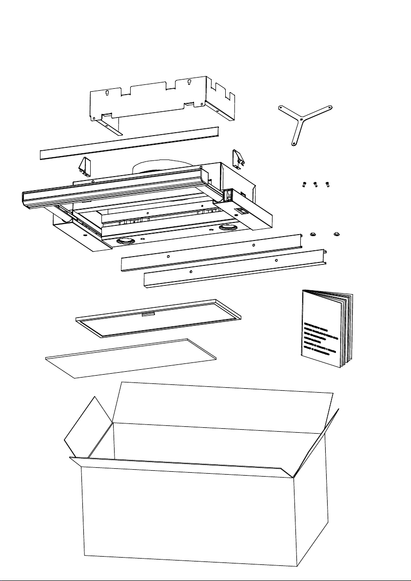
DECLIC 609 / 610
Composants
Components
Bauelemente
Componenti
Componentes
Onderdelen
Page 3
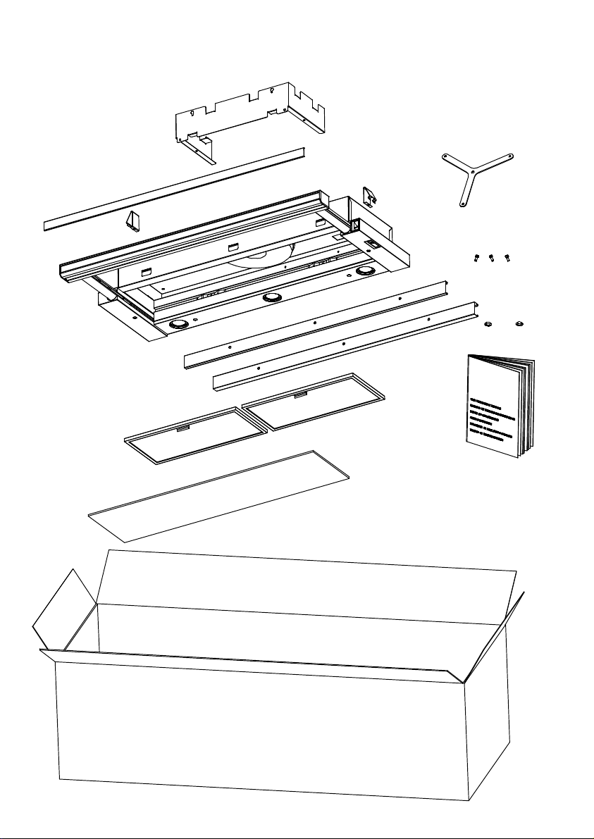
DECLIC 909 / 910
Composants
Components
Bauelemente
Componenti
Componentes
Onderdelen
Page 4

F SOMMAIRE 1
GB CONTENTS 5
RACCORDEMENT ÉLECTRIQUE
CONSEILS D’INSTALLATIONS
POSE DE L’APPAREIL
FONCTIONNEMENT
CONSEILS D’UTILISATIONS
ENTRETIEN
GARANTIE ET SERVICE APRÈS-VENTE
REMARQUES
D INHALT 9
NETZANSCHLUSS
MONTAGEHILFEN
MONTAGE DES GERÄTES
BETRIEB DES GERÄTES
NUTZUNG
WARTUNG UND REINIGUNG
GARANTIE UND KUNDENDIENST
WICHTIGE HINVEISE
ELECTRICAL WIRING
INSTALLATION ADVICE
FITTING THE APPLIANCE
OPERATION
USEFUL HINTS
MAINTENANCE
GUARANTEE AND AFTER-SALES-SERVICES
REMARKS
I SOMMARIO 14
COLLEGAMENTO ELETTRICO
CONSIGLI PER L' INSTALLAZIONE
POSA DELL’ APPARECCHIO
FUNZIONAMENTO
CONSIGLI DI UTILIZZO
MANUTENZIONE
GARANZIA ED ASSISTENZA TECNICA
NOTE
E SUMARIO
19
CONEXION ELECTRICA
CONSEJOS DE INSTALACION
INSTALACION DEL APARATO
FUNCIONAMIENTO
CONSEJOS DE UTILIZACION
MANTENIMIENTO
GARANTIA Y ASSISTENCIA TECNICA
NOTA
NL INHOUD 24
ELECTRISCHE BEDRADING
MONTAGE AANWIJZING
AANSLUITEN VAN HET APPARAAT
FUNKTIONEREN
GEBRUIKSADVIES
ONDERHOUD
AFTER SALES SERVICE
OPMERKINGEN
Page 5
Nous vous remercions de la confiance que vous nous avez accordée en choisissant un appareil de la
gamme ROBLIN.
Celui-ci a fait l’objet de toute notre attention dans sa conception et sa réalisation.
Afin qu’il vous donne entière satisfaction, nous vous recommandons de lire avec attention cette notice
qui vous expliquera comment l’installer, l’utiliser et l’entretenir dans les meilleures conditions.
1 RACCORDEMENT ÉLECTRIQUE
• La hotte est équipée d’un cordon d’alimentation de type HO5VVF 3 x 0,75 mm² comportant une
fiche normalisée 10/16 A avec système de mise à la terre.
Mode de protection : classe 1. Tension d’alimentation : 220-240 V mono - 50/60Hz.
Vérifier que la tension du secteur est identique aux valeurs indiquées sur la plaque signalétique à l’inté-
rieur de la hotte
• Si la hotte est raccordée directement sur le réseau sans sa fiche, un interrupteur omnipolaire avec
une ouverture de contact de 3 mm doit être installé avant la hotte. Le fil de terre (Jaune / vert) ne doit pas
être interrompu par cet interrupteur.
2 CONSEILS D’INSTALLATION
• Pour un fonctionnement idéal, nous vous conseillons une plage de hauteur de pose qui se situe de
0,65 m à 0,70 m au-dessus du plan de cuisson. Toutefois, il est formellement interdit d’installer toute
hotte ou groupe d’aspiration à une distance inférieure à 0,65 m du plan de travail (risque d’inflammation des filtres). La fumée doit monter naturellement vers la zone de captation.
• Respecter le diamètre de sortie de l’appareil : la hotte ne doit en aucun cas être raccordée à un
conduit de ventilation mécanique contrôlée (V.M.C.).
• Lorsqu’on évacue l’air vicié dans un conduit d’évacuation, veiller à ce que celui-ci ne soit pas déjà
exploité à véhiculer des gaz ou fumées provenant d’appareils alimentés par une énergie autre qu’électrique.
• Positionner le plan de cuisson au plus près de l’évacuation et éviter la formation de coudes sur la
gaine, afin de réduire au maximum les pertes de charges.
• Dans tous les cas d’installation, veiller au bon renouvellement d’air de la cuisine. Penser à effectuer une ou des entrées d’air par une grille de section égale ou supérieure au diamètre du tuyau
d’évacuation, afin de ne pas mettre la cuisine en dépression.
• Prévoir une aération suffisante lorsqu’un appareil de cuisson ou autre utilise simultanément l’air
ambiant de la pièce où est installée la hotte.
• La dépression maximum crée dans la pièce doit être inférieur à 0.04 mbar, ce qui évite un retour de
gaz de combustion.
• L’appareil doit être positionné de telle façon que la fiche d’alimentation soit accessible.
F
3 POSE DE L’APPAREIL.
Montage et raccordement doivent être réalisés par un installateur* qualifié.
(*) Le non-respect de cette condition entraîne la suppression de la garantie du constructeur et
tout recours en cas d’accident.
Groupe DECLIC + Moteur CONFORT PRO
La pose de l’appareil DECLIC peut être effectuer de 2 manières différentes :
• Soit en intégrant le moteur à la hotte ou au meuble.
• Soit en dissociant le moteur, pour être placé à distance, afin de diminuer la nuisance sonore .
Groupe DECLIC + Moteur MISTRAL 800
La pose de l’appareil DECLIC s’effectue seule, le moteur MISTRAL est fixé sur un mur extérieur.
1
Page 6

F
A - POSE AVEC MOTEUR INTÉGRÉ (CONFORT PRO)
1. Visser les 2 clips réglables sur le groupe DECLIC. (fig 1)
2. Positionner la buse du moteur sur celle du groupe. (fig 2).
3. Fixer l’ensemble à l’aide des 2 vis du couvercle du moteur .(fig 3).
4. Cliper les amortisseurs sur le moteur (fig 4)
5. Une plaque de compensation, de largeur 10 mm, est fixé à l’arrière du groupe DÉCLIC.
Si nécessaire, elle peut être enlevée ou remplacée par un plaque de compensation de 20 mm
(fournie).
Dévisser les 2 vis situées entre les lampes. Déposer la platine lumière afin d’accéder aux fixations
de la plaque de compensation. (fig. 5)
6. Percer le plancher de l’élément suivant les indications de la figure 6.
7. Insérer le groupe dans la découpe. Les 2 clips de fixation permettent par leurs élasticité un pose très
rapide. Resserrer les vis si nécessaire. (fig 1)
8. Il est conseillé de fixer le moteur CONFORT PRO à la paroi verticale du meuble si celui-ci le permet
(fig 7)
9. Mettre en place les obturateurs. (fig 8)
10. Raccorder la tuyauterie à la buse du moteur
11. Raccorder électriquement les 2 appareils. (fig 9)
(voir aussi paragraphe RACCORDEMENT ELECTRIQUE)
Attention les points 10 et 11 seront traités avant le point 7 si l ‘accessibilité ne permet pas de les
traiter après.
• Recyclage
L’air filtré est evacué dans la pièce à travers une ouverture placée sur la partie supérieure du meuble ou
de la hotte (fig. 10).
Fixer l’étrier sur le corps par 3 vis M4 x 6. Fixer ensuite la cartouche filtrante (fig 11)
B - POSE AVEC MOTEUR A DISTANCE (CONFORT PRO OU MISTRAL 800)
Se rapporter à la notice du moteur pour la pose de celui-ci.
1. Visser les 2 clips réglables sur le groupe DECLIC. (fig 1)
2. Une plaque de compensation, de largeur 10 mm, est fixé à l’arrière du groupe DÉCLIC.
Si nécessaire, elle peut être enlevée ou remplacée par un plaque de compensation de 20 mm
(fournie).
Dévisser les 2 vis situées entre les lampes. Déposer la platine lumière afin d’accéder aux fixations
de la plaque de compensation. (fig. 5)
3. Percer le plancher de l’élément suivant les indications de la figure 6.
4. Insérer le groupe dans la découpe. Les 2 clips de fixation permettent par leurs élasticité un pose très
rapide. Resserrer les vis si nécessaire. (fig 1)
5. Mettre en place les obturateurs. (fig 8)
6. Raccorder la tuyauterie à la buse de l’appareil
7. Raccorder électriquement les 2 appareils. (fig 9)
(voir aussi paragraphe RACCORDEMENT ELECTRIQUE)
Attention les points 6 et 7 seront traités avant le point 4 si l ‘accessibilité ne permet pas de les
traiter après.
C - REMPLACEMENT DU BANDEAU DECORATIF
Le bandeau peut être démonté et remplacé par un bandeau de même finition que le meuble.
1. Déposer la vitre (voir paragraphe 6 ENTRETIEN).
2
Page 7

2. Défaire l’embout droit du bandeau. Enlever la réglette aluminium afin d’accéder aux vis de fixation du
bandeau. Déposer le bandeau. (fig 13)
3. Usiner le nouveau bandeau suivant la figure 14.
Fixer la règle fourni sur les coulisseaux du groupe déclic. Fixer le bandeau sur la règle (fig 15)
4 FONCTIONNEMENT
Accés aux fonctions par ouverture du tiroir.
• Lumière : par interrupteur marche arrêt (fig 16)
• Moteur : par variation electronique (fig 17)
Arrêt automatique des fonctions par fermetue du tiroir.
5 CONSEILS D’UTILISATION
• Pour obtenir une efficacité maximum d’absorption des fumées ou des vapeurs, faire fonctionner
l’appareil 5 minutes environ avant et après la cuisson des aliments; La première vitesse est conseillée
pour les cuissons à feu doux et pour les sauces. La deuxième pour les cuissons soutenues, grillades et
friteuses. La troisième est indiquée pour les cuissons à forte émanation de graisses et vapeur.
• IMPORTANT . NE JAMAIS FLAMBER DE METS AU DESSOUS DE L’APPAREIL
Ne laissez jamais de flammes libres sous la hotte en fonctionnement.
• Les fritures nécessitent une surveillance permanente, l’huile surchauffée pouvant s’enflammer.
6 ENTRETIEN
Déconnecter le câble d’alimentation pour toute intervention électrique.
L’appareil a été conçu pour faciliter au maximum les opérations d’entretien, synonyme de bon fonction-
nement et rendement de l’appareil dans le temps.
• Dépose de la vitre
Celle-ci peut être enlevée afin de faciliter son nettoyage.
Pousser la vitre dans son logement afin de la faire basculer (fig 12)
• Nettoyage des filtres métalliques.
Il est indispensable de procéder à un NETTOYAGE PÉRIODIQUE de ces filtres à la main (avec un
détergent liquide à l’eau tiède et rinçage) ou au lave- vaisselle (tous les deux mois environ pour une
utilisation normale).
• Carrosserie.
Nettoyer régulièrement celle-ci en utilisant des produits détergents, non abrasifs et une éponge légèrement humide. N’utilisez jamais d’éponges ou de chiffons trempés
N’introduisez aucun objet, ni les mains dans l’ouverture servant à l’évacuation de l’air
• Conduit d’évacuation.
Vérifier tous les 6 mois le bon écoulement de l’air vicié.
Observer les prescriptions réglementaires locales concernant l’évacuation de l’air vicié.
• Éclairage.
Avant toute intervention sur l’appareil, mettre l’interrupteur d’allumage des lampes en position éteinte.
Ne pas dépasser la puissance prescrite et ne pas changer de type de lampe.
F
7 GARANTIE ET SERVICE APRÈS-VENTE
• En cas d’anomalie de fonctionnement, prévenez votre installateur qui devra vérifier l’appareil et son
raccordement.
• Dans le cas où un composant électrique viendrait à être endommagé, celui-ci ne peut être remplacé que par un atelier de réparation reconnu par le fabricant, car des outils spéciaux sont nécessaires.
3
Page 8

F
• Débrancher complètement l’appareil.
• Exigez toujours l’utilisation de pièces de rechange d’origine. La non observation de cette prescription peut compromettre la sécurité de l’appareil.
• Lors de la commande de pièces détachées, rappeler le numéro de l’appareil inscrit sur la plaque
signalétique située à l’intérieur de la hotte.
• Seule la facture d’achat de l’appareil fera foi pour l’application de la garantie contractuelle.
Cette garantie ne couvre pas les consommables comme :
- L’éclairage : lampes incandescentes, halogènes ...
- Les filtres.
8 REMARQUES
Nos appareils sont conformes aux normes harmonisées CEI 335 et aux directives européennes basse
tension 73/23 et compatibilité électromagnétique 89/336.
4
Page 9

Thank you for buying a Roblin product which has been manufactured to the highest quality standards to
meet your requirements.
We recommend you carefully read this booklet in which you will find instructions for installation, hints for
use and maintenance.
1 ELECTRICAL
• This cooker hood is fitted with a 3-core mains cable with a standard 10/16A earthed plug.
• Alternatively the hood can be connected to the mains supply via a double-pole switch having 3mm
minimum contact gap on each pole.
• Before connecting to the mains supply ensure that the mains voltage corresponds to the voltage on
the rating plate inside the cooker hood.
• Technical Specification: Voltage 220-240, single phase ~50/60Hz.
2 INSTALLATION ADVICE
• Ensure the cooker hood is fitted in compliance with the recommended fixing heights.
• To ensure the safe operation of this cooker hood, we recommend that the hood should not be fitted
below 65cm (for electric) or (70cm for gas) the measurements taken from the surface of the cooking
appliance to the underside of the cooker hood.
• It is a possible fire risk if the hood is not sited as recommended.
• To ensure the best results, the cooking fumes should be able to rise naturally towards the inlet grilles
on the underside of the cooker hood and the cooker hood should be positioned away from doors and
windows, which will create turbulence.
• Ducting
• If the room where the hood is to be used contains a fuel-burning appliance such as a central heating
boiler then its flue must be of the room sealed or balanced flue type.
• If other types of flue or appliances are fitted ensure that there is an adequate supply of fresh air to the
room. Ensure the kitchen is fitted with an airbrick, which should have a cross-sectional measurement
equivalent to the diameter of the ducting being fitted, if not larger.
• The ducting system for this cooker hood must not be connected to any existing ventilation system,
which is being used for any other purposes or to a mechanically controlled ventilation ducting.
• The ducting used must be made from fire retardant materials and the correct diameter must be used,
as incorrect sized ducting will affect the performance of this cooker hood.
• When the cooker hood is used in conjunction with other appliances supplied with energy other than
electricity, the negative pressure in the room must not exceed 0.04 mbar to prevent the fumes from
combustion being drawn back into the room.
• The appliance is for domestic use only and should not be operated by children or people who are
infirm without supervision.
• This appliance must be positioned so that the wall socket is accessible.
3 FITTING
Any permanent electrical installation must comply with the latest regulations concerning this type of
installation and a qualified electrician must carry out the work. Non-compliance could cause serious
accidents or injury and would deem the manufacturers guarantee null and void.
IMPORTANT - The wires in this mains lead are coloured in accordance with the following code :
green / yellow : earth blue : neutral brown : live
As the colours of the wires in the mains lead of this appliance may not correspond with the coloured
markings identifying the terminals in your plug, proceed as follows.
- The wire which is coloured green and yellow must be connected to the terminal in the plug which is
marked with the letter E or by the earth symbol
- The wire which is coloured blue must be connected to the terminal which is marked with the letter N or
coloured black.
- The wire which is coloured brown must be connected to the terminal which is marked with the letter L or
coloured red.
or coloured green or green and yellow..
GB
5
Page 10

GB
Telescopic DECLIC + CONFORT PRO Motor
The installation of the built-in telescopic DECLIC can be carried out in 2 different ways:
• Either while integrating the motor in the hood or in the kitchen furniture.
• Either while separating the motor, to be placed at a distance, in order to be more comfortable improving
noise level
Telescopic DECLIC + Remote MISTRAL 800 external motor
The Mistral 800 external motor is installed with the built-in DECLIC telescopic extractor in the kitchen
furniture, or remotely at a distance fitted on an outside wall.
A - INSTALLATION WITH THE CONFORT PRO MOTOR FIXED INTO THE BUILT-IN TELESCOPIC
EXTRACTOR
1. Turn the screws anticlockwise to loosen the 2 fixing clips on the Declic (fig 1).
2. Position the Confort motor inlet above the Declic and lower into position (fig 2).
3. Fix the Declic motor assembly to the Confort with the 2 screws (fig 3).
4. Insert the 4 shock absorbers into the holes in the back of the Confort motor (fig 4).
5. The Declic is supplied with a 10mm and 20mm spacer to fill the gap between the wall and the rear
of the extractor. To fit the spacer unscrew the screws located between the halogen lights and remove
the front light housing in order to access (fig.5).
6. Cut the require aperture in the base of the kitchen cabinet as indicated (fig. 6).
7. Insert the telescopic extractor in the aperture in the kitchen cabinet and turning the screws clockwise
secure the assembly to the kitchen cabinet (fig 1).
8. We recommend that the CONFORT PRO motor be secured to the back of the kitchen cabinet,
which will allow access via the cabinet door (fig 7).
9. Insert the grommets into the screw holes (fig 8).
10. Connect the ducting onto the round outlet on the top of the motor assembly.
11. Connect both appliances together (fig 9) and connect them to the mains supply (See ELECTRICAL
WIRING chapter).
CAUTION : If the kitchen cabinet does not have a door you must execute points 10 and 11 before
point 7.
• RECIRCULATION
In the recirculation mode (with the optional activated charcoal filter fitted) the contaminated air enters the
hood through the grease filter and through the purifying activated charcoal filters and back out into the
kitchen through a grille in the front of the kitchen cabinet (fig. 10).
Before the charcoal filter can be fitted it is necessary to fix the propeller shaped bracket over the outlet in
the body of the canopy using the 3 No M4 x 6 screws provided and then the activated charcoal cartridge
can be fitted (fig 11).
B - REMOTE INSTALLATION OF THE DECLIC WITH CONFORT PRO OR MISTRAL 800 MOTOR
See the specific instruction booklet supplied when fitting the remote controlled Confort or Mistral 800 motor
at a distance from the Declic extractor hood.
1. Turn the screws anticlockwise to loosen the 2 fixing clips on the Declic (fig 1).
2. The Declic is supplied with a 10mm and 20mm spacer to fill the gap between the wall and the rear of
the extractor. To fit the spacer unscrew the screws located between the halogen lights and remove the
front light housing in order to access (fig.5).
3. Cut the require aperture in the base of the kitchen cabinet as indicated (fig. 6).
4. Insert the telescopic extractor in the aperture in the kitchen cabinet and turning the screws clockwise
secure the assembly to the kitchen cabinet (fig 1).
6
Page 11

5. Insert the grommets into the screw holes (fig 8).
6. Connect the ducting onto the round outlet on the top of the motor assembly.
7. Connect both appliances together (fig 9) and connect them to the mains supply (See ELECTRICAL
WIRING chapter).
CAUTION : If the kitchen cabinet does not have a door you must execute points 6 and 7 before
point 4.
C - REPLACING THE DECORATIVE FRONT STRIP
You can replace the strip in the front trim with a matching strip of kitchen furniture finish or with a complete
piece of cornice.
1. Remove the glass (See chapter 6: MAINTENANCE).
2. When replacing the front strip with matching laminate. Firstly, remove the right-hand end capping from
the front trim and slide out the aluminium front strip plate. Secondly, insert the cut piece of laminate
and replace the right-hand end capping.
3. When replacing the whole front trim with a piece of lighting pelmet or similar. Firstly, remove the righthand end capping and the aluminium strip to access to the front fixing screws. Secondly, cut the new
front trim in accordance with the dimension contained in fig.14 and machine finish the new strip before
fixing the trim and metal plate using the original screws (fig.15).
4 OPERATION
Access to the functions by opening of the side.
• Lighting : By rock-switch ON / OFF ( Fig. 16 ).
• Motor : By dimmer switch ( Fig. 17).
Automatic stop of the functions by closing of the side.
GB
5 USEFUL HINTS
• To obtain the best performance it is advisable to switch ‘ON’ the cooker hood a few minutes (in the boost
setting) before you start cooking and you should leave it running for approximately 15 minutes after finishing.
• IMPORTANT: NEVER DO FLAMBÉ COOKING UNDER THIS COOKER HOOD
• Do not leave frying pans unattended during use as over-heated fat and oil might catch fire.
• Do not leave naked flames under this cooker hood.
• Switch ‘OFF’ the electric and gas before removing pots and pans.
• Ensure heating areas on your hotplate are covered with pots and pans when using the hotplate
and cooker hood simultaneously.
6 MAINTENANCE
Before carrying out any maintenance or cleaning isolate the cooker hood from the mains supply.
The cooker hood must be kept clean; a build up of fat or grease can be a fire hazard.
Remove the glass.
It is possible to remove the glass for ease of cleaning by sliding the glass to the left, which will allow it to
hinge down and be removed as illustrated (fig.12).
Casing
• Wipe the cooker hood frequently with a clean cloth, which has been immersed in warm water containing
a mild detergent and wrung out.
• Never use excessive amounts of water when cleaning particularly around the control panel.
• Never use scouring pads or abrasive cleaners.
• Always wear protective gloves when cleaning the cooker hood.
Metal Grease Filters : The metal grease filters absorb grease and dust during cooking to help keep the
cooker hood clean inside. The grease filters should be cleaned once a month or more frequently if the
hood is used for more than 3 hours per day.
7
Page 12

GB
To remove and replace the metal grease filters
• Remove the metal grease filters one at a time by releasing the catches on the filters; the filters can
now be removed.
• The metal grease filters should be washed, by hand, in mild soapy water or in a dishwasher.
• Allow to dry before replacing.
Extraction tube : Check every 6 months that the dirty air is being extracted correctly. Comply with local
rules and regulations with regard to the extraction of ventilated air.
Lighting : If the lamp fails to function check to ensure it is fitted correctly into the holder. If lamp failure
has occurred then it should be replaced with identical replacement.
Do not replace with any other type of lamp and do not fit a lamp with a higher rating.
7 GUARANTEE AND AFTER SALES SERVICE
• In the event of any malfunction or anomaly, notify your fitter who will have to check the appli-
ance and its connection.
• In the event of damage to the mains supply cable, this can only be replaced by at approved repair
centre appointed by the manufacturer who have the necessary tools and equipment to carry out any
repairs properly. Repairs carried out by other persons will invalidate the guarantee.
• Use only genuine spare parts. Should these warnings fail to be observed it could affect the safety of
your cooker hood.
• When ordering spare parts quote the model number and serial number written on the rating plate,
which is found on the casing behind the grease filters inside the hood.
• Proof of purchase will be required when requesting service. Therefore, please have your receipt
available when requesting service as this constitutes the date from which your guarantee commenced.
This Guarantee does not cover :
- Damage or calls resulting from transportation, improper use or neglect, the replacement of any light
bulbs or filters or removable parts of glass or plastic.
These items are considered to be consumable under the terms of this guarantee.
8 REMARKS
Your appliance comply with harmonised standards CEI 335 and the Europeans’ directives (Low voltage)
73/23 and ( Electromagnetic compatibility ) 89/336.
8
Page 13

1
2
25
Page 14

3
26
4
Page 15

5
6
7
A
B
DECLIC 609/610
A = 514 mm
B = 255 mm
DECLIC 909/910
A = 814 mm
B = 255 mm
8
9
27
Page 16

10
12
11
28
Page 17

13
14
15
16
17
29
Page 18

30
Page 19

k
e
tihW
kn
c
alB
i
P
e
u
l
B-
nw
t
r
h
u
or
z
g
i
A
B
L
Black
AZUR - AZUR - AZUR BLAU
BLACK - NOIR- SCHWARZ
BLUE - BLEU - BLAU
BROWN - BRUN - BRAUN
GREEN YELLOW - VERT JAUNE - GRÜN GELB
GREY - GRIS - GRAU
LIGHT BLUE - BLEU CLAIR - HELL BLAU
PINK - ROSE - ROSA
PURPLE - MAUVE - MALVER FARBIG
WHITE - BLANC - WEISS
YELLOW - JAUNE - GELB
ye
rG
e
l
pruP
d
e
R
Ha logen S potlight
600 : 2 x 50 W - 230 V
900 : 3 x 50 W - 230 V
31
Page 20

UK ELECTRICAL CONNECTION
ECTRICAL REQUIREMENTS
EL
Any permanent electrical installation must comply
with the latest I.E.E. Regulations and local Electricity
Board regulations. For your own safety this should be
un
dertaken by a qualified electrician e.g. your local
Electricity Board, or a contractor who is on the roll of
the National Inspection Council for Electrical
Inst
allation Contracting (NICEIC).
ELECTRICAL CONNECTION
Before connecting to the mains supply ensure that
the mains voltage corresponds to the voltage on the
rating plate inside the cooker hood.
This appliance is fitted with a 2 core mains cable and
must be permanently connected to the electricity supply
via a double-pole switch having 3mm minimum contact
gap on each pole. A Switched Fuse Connection Unit
to BS.1363 Part 4, fitted with a 3 Amp fuse, is a
rec
ommended mains supply connection accessory to
ensure compliance with the Safety Requirements
ap
plicable to fixed wiring instructions.
The wires in this mains
lead are coloured in
ac
cordance with the
following code:
Blue Neutral
Brown Live
As the colours of the wires
in the mains lead of this
appliance may not
co
rrespond with the
coloured markings
ide
ntifying the terminals in
your connection unit,
proceed as follows:-
The wire which is coloured blue must be connected
to the terminal which is marked with the letter ‘N’ or
coloured black.
The wire which is coloured brown must be connected
to the terminal which is marked with the letter ‘L’ or
coloured red.
32
Page 21

ACCESSOIRES ACCESSORI
ACCESSORIES ACCESORIA
ZUBEHÖRE
GU10
50 W - 230 V
Code 12EC006
ACCESSOIRES
5403003
33
Page 22

A
CD
B
EF
34
F
Page 23

G
H
J
I
K
L
35
Page 24

Plaque Signalétique de la hotte
Rating plate of the cookerhood
Typenschild im Inneren der Dunstesse
Etichetta all'interno della cappa
Etiqueta de la campana
Typeplaatje van de afzuigkap
Numéro de série
Serial number
Seriennummer
Numero di serie
Numero de serie
Serienummer
Modèle
Model
Modell
Modello
Modelo
Model
37
Page 25

F - Votre produit est conçu et fabriqué avec des matériaux et des composants
de haute qualité, qui peuvent être recyclés et utilisés de nouveau.
Lorsque ce symbole d’une poubelle à roue barrée est attaché à un produit,
cela signifie que le produit est couvert par la Directive Européenne 2002/96/EC.
Veuillez vous informer du système local de séparation des déchets électriques
et électroniques.
Veuillez agir selon les règles locales et ne pas jeter vos produits usagés avec
les déchets domestiques usuels. Jeter correctement votre produit usagé aidera à prévenir les
conséquences négatives potentielles contre l’environnement et la santé humaine.
GB - Your product is designed and manufactured with high quality materials and components,
which can be recycled and reused.
When this crossed-out wheeled bin symbol is attached to a product it means the product is
covered by the European directive 2002/96/EC.
Please inform yourself about the local separate collection system for electrical and electronic
product.
Please act according to your local rules and do not dispose of your old products with your
normal household waste. The correct disposal of your old product will help prevent potential
negative consequences for the environment and human health.
D - Ihr Produkt ist au hochqualitativen Materialien und Bestandteilen hergestellt, die dem
Recycling zugefürht und wiederverwertet werden können.
Falls dieses Symbol eines durchgestrichchenen Müllcontainers auf Rollen auf diesem Produkt
angebracht ist, bedeutet dies, dass es von der Europäischen Richtlinie 2002/96/EG erfasst wird.
Bitte informieren Sie sich über die örtlichen Sammelstellen für Elektroprodukte und elektronische
Geräte.
Bitte beachten Sie die lokalen Vorschriften und entsorgen Sie Ihre Altgeräte nicht mit dem
normalen Haushaltsmüll. Die korrekte Entsorgung Ihres Altgerätes ist ein Beitrag zur Vermeidung möglicher negativer Folgen für die Umwelt und die menschliche gesundhei.
I - Questo prodotto è stato progettato e fabbricato con materiali e componenti di alta qualità, che
posssono esere riciclati e riutilizzati.
Quando ad un prodotto è attaccato il simbolo del bidone con le ruote segnato da una croce,
significa che il prodotto è tutelato dalla Directiva Europea 2003/96/EC.
Si prega di informarsi in merito al sistema locale di raccolta differenziata per i prodotti elettrici ed
elettronici.
Rispettare le norme locali in vigore e non smaltire i prodotti vecchi nei normali rifiuti domestici. Il
correto smaltimento del prodotto aiuta ad evitare possibili conseguenze negative per la salute
dell’ambiente e dell’uomo.
E - Su producto ha sido diseñado y fabricado con materiales y componentes de alta calidad,
que pueden ser reciclados y reutilizados.
Cuando vea este símbolo de una papelera con ruedas tachada junto a un producto, esto significa
que el producto está bajo la Directiva Europea 2002/96/EC.
Deberá informarse sobre el sistema de reciclaje local separado para productos eléctricos y
electrónicos.
Siga las normas locales y no se deshaga de los productos usados tirándolos en la basura normal
de su hogar. El reciclaje correcto de su producto usado ayudará a evitar consecuencias negativas
para el medio ambiente y la salud de las personas.
Page 26

NL - Uw apparaat werd ontworpen met en vervaardigd uit onderdelen en materialen van
superieure kwaliteit, die gerecycleerd en opnieuw gebruikt kunnen worden.
Wanneer het symbool van een doorstreepte vuilnisemmer op wielen op een product is bevestigd,
betekent dit dat het product conform is de Europese Richtlijn 2002/96/EC.
Gelieve u te informeren in verband met het plaatselijke inzamelingsysteem voor elektrische en
elektronische apparaten.
Gelieve u te houden aan de plaatselijke reglementering en apparaten niet met het gewone huisvuil
mee te geven.
Door afgedankte apparaten op een correcte manier weg te werpen help u mogelijke negatieve
gevolgen voor het milieu en de gezondheid te voorkomen.
Page 27

Cet équipement est conforme à la norme européenne sur la basse tension C.E.E. 73/23 relative
à la sécurité électrique et aux normes européennes: C.E.E. 89/336 relative à la compatibilité
électromagnétique et C.E.E. 93/68 relative au marquage CE.
This appliance complies with European regulations on low voltages, EEC Directive 73/23 on
electrical safety, and with the following European regulations: EEC Directive 89/336 on
electromagnetic compatibility and EEC Directive 93/68 on EC marking.
Dieses Gerät entspricht den europäischen Niederspannungsrichtlinien 73/23/EWG zur
elektrischen Sicherheit, den europäischen Richtlinien 89/336/EWG zur elektromagnetischen
Verträglichkeit und den Richtlinien 93/68/EWG zur CE-Kennzeichnung
Quest’apparecchio é conforme alla norma europea sulla bassa tensione C.E.E. 73/23 relativa
alla sicurezza elettrica e alle norme europee: C.E.E. 89/336 relativa alla compatibilità elettromagnetica e C.E.E. 93/68 relativa alla marcatura CE.
Este aparato esta en conformidad con la norma europea en relación con baja tensión C.E.E 73/
23 de la securidad electrica y a las normas europeas C.E.E 89/336 en relatión con la compatibilad
electromagnetica y C.E.E 93/68 en relación con la marcación CE.
Dit apparaat voldoet aan de Europese Laagspanningsrichtlijn 72/23/EEG inzake de elektrische
veiligheid en aan de Europese normen 89/336/EEG inzake de elektromagnetische compatibiliteit
en 93/68/EEG inzake de CE-markering.
ROBLIN S.A. - Route de Caen - Sainte Cécile - B. P. 56 - 50800 VILLEDIEU-LES-POËLES - France
Tél. 02 33 91 26 50 - Fax 02 33 51 54 79 - e-mail : com.France@roblin.fr
e-mail : com.export@roblin.fr
For outside France : Tel. +33 (0)2 33 91 26 57 - Fax. +33 (0)2 33 51 54 79
20NO089 - 061208
 Loading...