

Page 1
Instruction Manual
Manuel d’Instructions
Bedienungsanleitung
Page 2
INDEX
RECOMMENDATIONS AND SUGGESTIONS ..................................................................................................................... 4
CHARACTERISTICS ............................................................................................................................................................. 7
INSTALLATION ...................................................................................................................................................................... 9
USE ...................................................................................................................................................................................... 13
MAINTENANCE ................................................................................................................................................................... 14
EN
SOMMAIRE
CONSEILS ET SUGGESTIONS .......................................................................................................................................... 16
CARACTERISTIQUES ......................................................................................................................................................... 19
INSTALLATION .................................................................................................................................................................... 21
UTILISATION ....................................................................................................................................................................... 25
ENTRETIEN ......................................................................................................................................................................... 26
INHALTSVERZEICHNIS
EMPFEHLUNGEN UND HINWEISE ................................................................................................................................... 28
CHARAKTERISTIKEN ......................................................................................................................................................... 31
MONTAGE ........................................................................................................................................................................... 33
BEDIENUNG ........................................................................................................................................................................ 37
WARTUNG ........................................................................................................................................................................... 38
FR
DE
2
2
Page 3
EN
2°
RECOMMENDATIONS AND SUGGESTIONS
The Instructions for Use apply to several versions of this appliance.
Accordingly, you may find descriptions of individual features that do not
apply to your specific appliance.
INSTALLATION
•
The manufacturer will not be held liable for any damages resulting from
incorrect or improper installation.
• The minimum safety distance between the cooker top
and the extractor hood is 650 mm (some models can
be installed at a lower height, please refer to the
paragraphs on working dimensions and installation).
• Check that the mains voltage corresponds to that
indicated on the rating plate fixed to the inside of the
hood.
• For Class I appliances, check that the domestic
power supply guarantees adequate earthing.
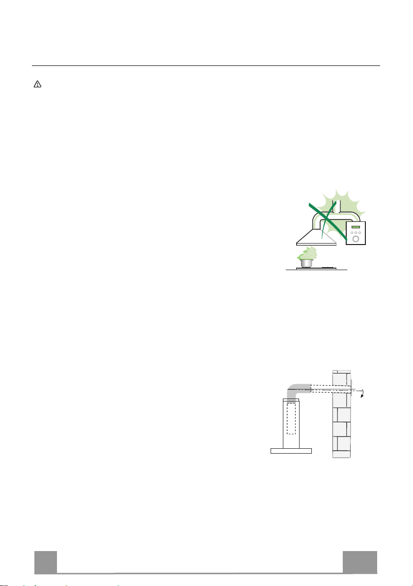
Connect the extractor to the exhaust flue through a pipe of minimum
diameter 120 mm. The route of the flue must be as short as possible.
• Do not connect the extractor hood to exhaust ducts carrying combustion
fumes (boilers, fireplaces, etc.).
• If the extractor is used in conjunction with nonelectrical appliances (e.g. gas burning
appliances), a sufficient degree of aeration must
be guaranteed in the room in order to prevent the
backflow of exhaust gas. The kitchen must have
an opening communicating directly with the open
air in order to guarantee the entry of clean air.
When the cooker hood is used in conjunction with
appliances supplied with energy other than electric, the negative pressure in
the room must not exceed 0,04 mbar to prevent fumes being drawn back
into the room by the cooker hood.
• In the event of damage to the power cable, it must be replaced by the
manufacturer or by the technical service department, in order to prevent any
risks.
4
4
Page 4
EN
• If the instructions for installation for the gas hob specify a greater distance
specified above, this has to be taken into account. Regulations concerning
the discharge of air have to be fulfilled.
• Use only screws and small parts in support of the hood.
Warning: Failure to install the screws or fixing device in accordance with
these instructions may result in electrical hazards.
• Connect the hood to the mains through a two-pole switch having a contact
gap of at least 3 mm.
USE
• The extractor hood has been designed exclusively for domestic use to
eliminate kitchen smells.
• Never use the hood for purposes other than for which it has been designed.
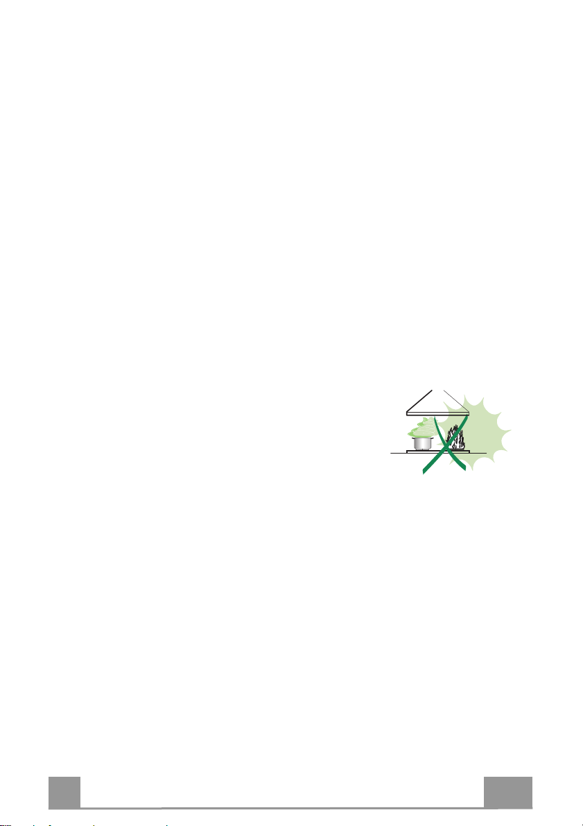
• Never leave high naked flames under the hood when it is in operation.
• Adjust the flame intensity to direct it onto the bottom of the pan only, making
sure that it does not engulf the sides.
• Deep fat fryers must be continuously monitored
during use: overheated oil can burst into flames.
• Do not flambè under the range hood; risk of fire.
• This appliance can be used by children aged from
8 years and above and persons with reduced
physical, sensory or mental capabilities or lack of
experience and knowledge if they have been given supervision or instruction
concerning use of the appliance in a safe way and understand the hazards
involved. Children shall not play with the appliance. Cleaning and user
maintenance shall not be made by children without supervision.
5
5
Page 5
EN
• “CAUTION: Accessible parts may become hot when used with cooking
appliances.”
MAINTENANCE
•
Switch off or unplug the appliance from the mains supply before carrying out
any maintenance work.
• Clean and/or replace the Filters after the specified time period (Fire hazard).
• The Grease filters must be cleaned every 2 months of operation, or more
frequently for particularly heavy usage, and can be washed in a dishwasher.
• The Activated charcoal filter is not washable and cannot be regenerated,
and must be replaced approximately every 4 months of operation, or more
frequently for particularly heavy usage.
• Clean the hood using a damp cloth and a neutral liquid detergent.
The symbol on the product or on its packaging indicates that this product
may not be treated as household waste. Instead it shall be handed over to the
applicable collection point for the recycling of electrical and electronic
equipment. By ensuring this product is disposed of correctly, you will help
prevent potential negative consequences for the environment and human
health, which could otherwise be caused by inappropriate waste handling of
this product. For more detailed information about recycling of this product,
please contact your local city office, your household waste disposal service or
the shop where you purchased the product.
6
6
Page 6
EN
11a
16
12c
12d
8
9
2.1
2.2
12c
12a
7.2.1 11
1
11
12a
12r
9
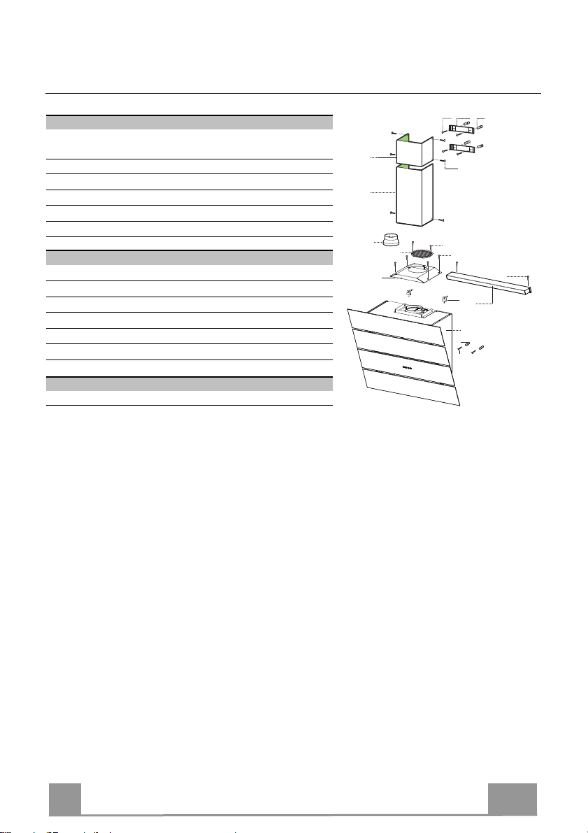
CHARACTERISTICS
Components
Ref. Q.ty Product Components
1 1 Hood Canopy complete with: Controls, Light, Fan unit,
Filters
2.1 1 Upper chimney
2.2 1 Lower chimney
5 1 Lighting unit
8 1 Directional air outlet grille
9 1 Reduction flange 150-120
16 1 Filter cover
Ref. Q.ty Installation Components
7.2.1 2 Upper chimney fixing brackets
11 6 Plugs
11a 2 SB 12/10 Wall Plugs
12a 6 Screws 4.2 x 44.4
12c 10 Screws 2.9 x 6.5
12r 2 Screws 2.9 x 6.5
12d 2 Screws 2.9 x 9.5
Q.ty Documentation
1 Instruction Manual
7
7
Page 7
EN
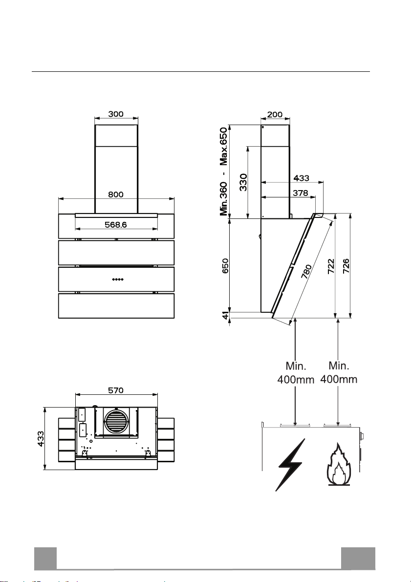
Dimensions
8
8
Page 8
EN
11a
1
1
2 2
210
11
12a
247 247
1004
482
400
210
X
1÷2
7.2.1
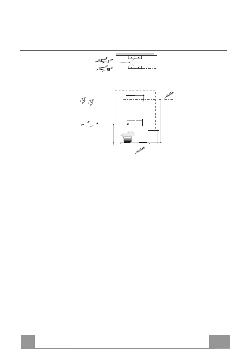
INSTALLATION
Wall drilling and bracket fixing
As a first step, proceed with the following drawings:
• a vertical line up to the ceiling or up to the upper limit, at the centre of the area in which the
hood is to be fitted;
• a horizontal line at a minimum 1004 mm above the cooker top.
• Mark a point (1) on the horizontal line, 247 mm to the right of the vertical reference line.
• Repeat this operation on the other side, checking that the two marks are levelled.
• Mark a reference point (2) as indicated at 210 mm from the vertical reference line and 482
mm above the cooker top.
• Repeat this operation on the other side, checking that the two marks are levelled.
• Drill at the marked points (1), using a ø 12 mm drill bit.
• Drill at the marked points (2) using a ø 8 mm drill bit.
• Insert the bracket plugs 11a into the holes (1) and tighten the screws.
• Insert plug 11 into holes (2).
To install a decorative chimney ( optional )
• Place bracket 7.2.1 on the wall, about 1-2 mm from the ceiling or from the upper limit,
aligning the centre (notch) with the vertical reference line.
• Mark the wall at the centres of the bracket holes.
• Place the bracket 7.2.1 on the wall at X mm below the first bracket (X = height of the upper
chimney section), aligning the centre (notch) with the vertical line.
• Mark the wall at the centres of the bracket holes.
• Drill ø 8 mm holes at all the marked centre points.
• Insert the wall plugs 11 in the holes.
• Fix the brackets using the 12a screws (4,2 x 44,4) supplied with the hood.
9
9
Page 9
EN 1
Fitting the hood body
12a
Vr
11a
ø 150
9
ø 120
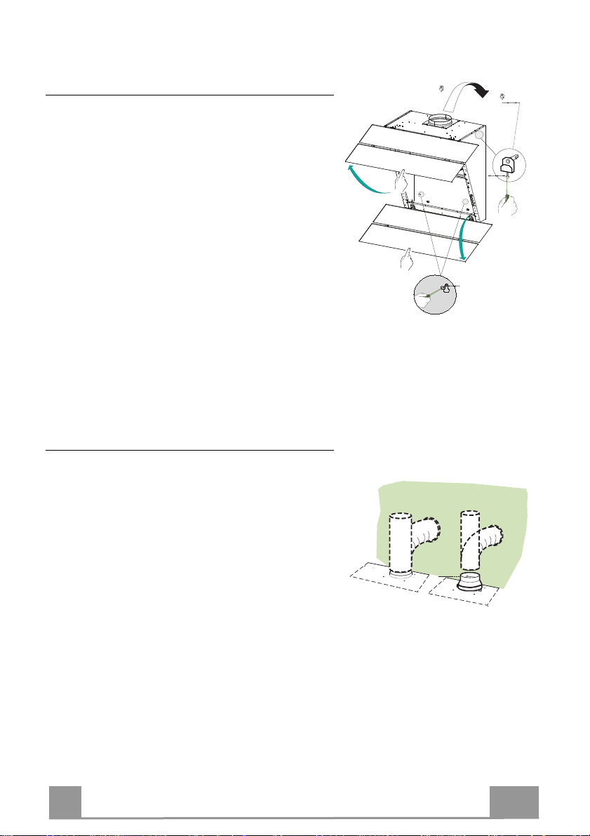
• Open the doors/the door (See section Open Panels).
• Remove the Metal grease filters using the handles
provided.
• Adjust the two screws Vr, in the brackets 11a, so that
they are at the start of their travel.
• Hook the hood body to the two brackets 11a.
• From the inside of the hood body, turn screws Vr to
level the hood body itself.
• Fasten the safety screw 12a.
• Close the doors/the door again.
Connections
DUCTED VERSION AIR EXHAUST SYSTEM
When installing the ducted version, connect the hood to
the chimney using either a flexible or rigid pipe ø 150
or 120 mm, the choice of which is left to the installer.
• To install a ø 120 mm air exhaust connection, insert
the reducer flange 9 on the hood body outlet.
• Fix the pipe in position using sufficient pipe clamps
(not supplied).
• Remove possible charcoal filters.
10
Page 10
EN 1
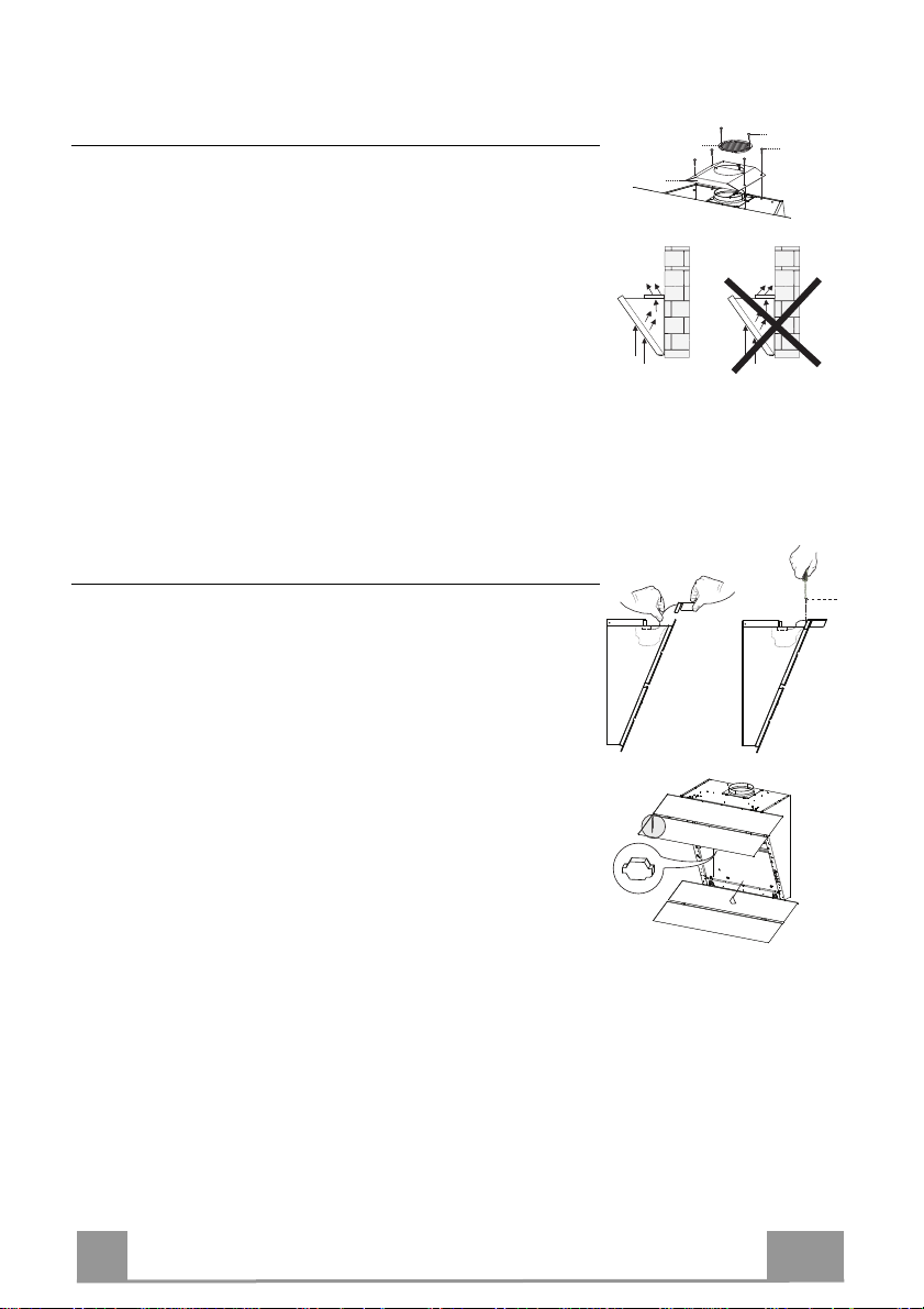
RECYCLING VERSION AIR OUTLET
16
12c
12d
8
12r
To install the hood in recycling version, the optional charcoal
filter kit must be purchased.
• Remove the chimney angle bracket.
• Screw the filter cover onto the air outlet, using four screws 12c
(2.9 x 12.5).
• Fix the air outlet grid 8 on the recirculation air outlet using the
2 screws 12d (2,9 x 9,5) provided.
Fitting the Lighting Unit
• Insert the Lighting unit cable into the opening.
• Rest the Lighting unit 9 .
• Fix it using the Screws 12r provided.
• Remove grease filters.
• Inside the hood canopy there is a wiring box for connection of
the lighting unit.
• Open the box and connect the wires to the terminal inside it,
checking that the colours are combined properly.
• Close the wiring box, replace the grease filters and close the
doors.
11
Page 11
EN 1
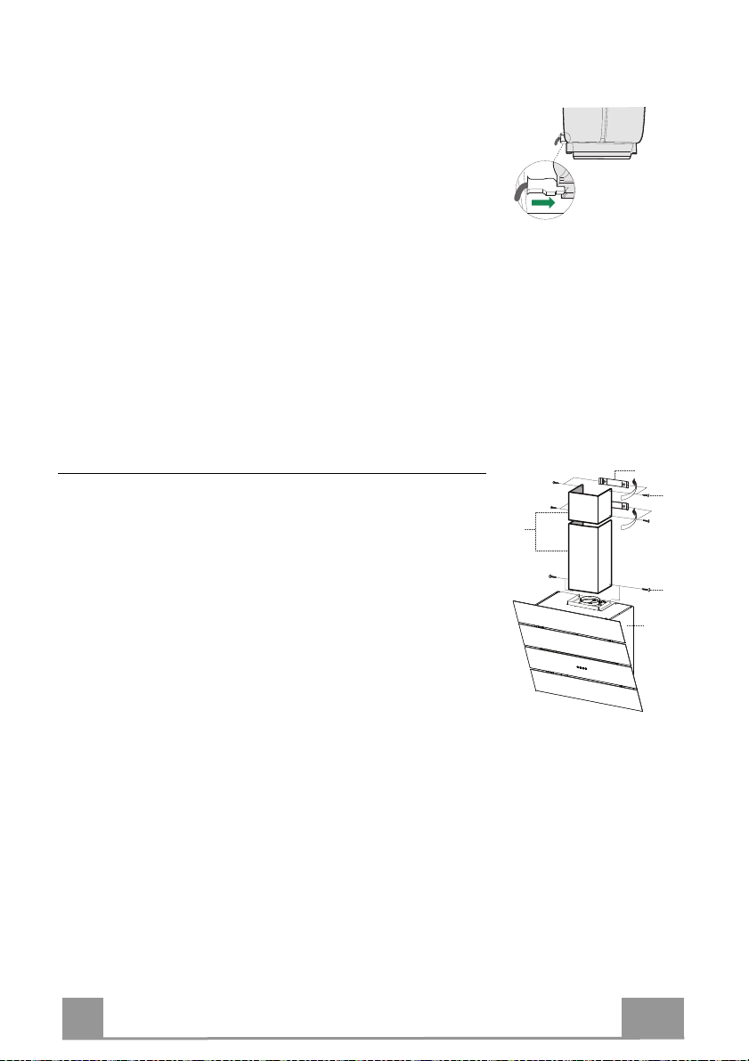
ELECTRICAL CONNECTION
12c
2.1
2.2
2
7.2.1
12c
1
• Connect the hood to the mains through a two-pole switch
having a contact gap of at least 3 mm.
• Remove the grease filters (see paragraph Maintenance) being
sure that the connector of the feeding cable is correctly inserted
in the socket placed on the side of the fan.
Chimney assembly
Upper exhaust Chimney
• Slightly widen the two sides of the upper chimney and hook
them behind the brackets 7.2.1, making sure that they are well
seated.
• Secure the sides to the brackets using the 4 screws 12c (2,9 x
9,5) supplied.
Lower exhaust Chimney
• Slightly widen the two sides of the chimney and hook them
between the upper chimney and the wall, making sure that they
are well seated.
• Fix the lower part laterally to the hood body using the 2 screws
12c (2,9 x 9,5) supplied.
12
Page 12
EN
1
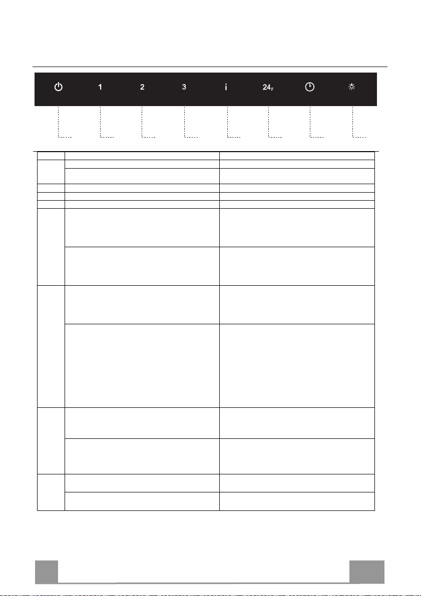
Button Function
Led
A Turns the Motor off.
The Leds indicating the Speed of the motor turn off.
Enables / Disables Keyboard Lock mod
e if pressed and
All the Leds light up in cycle.
B Activates speed one.
The Leds indicating Speed one and Motor Off turn on.
C Activates speed two.
The Leds indicating Speed two and Motor Off turn on.
D
Activates speed three.
The Led
s indicating Speed three and Motor Off turn on.
E
Activates
Intensive
speed. This speed is timed to run
Flashes once a second.
Press and hold the button for approximately 5 seconds,
seconds.
Button A
Led flashes twice.
F
Starts the
24H
function, in which the motor starts at a
The Leds indicating
24H
speed and Motor Off turn on.
When the filters alarm is triggered, the alarm can be
When the procedure terminates, the indication shown
for 200 working hours.
G
Activates
Delay
mode, with automatic shutdown of the
The
Delay
Led lights up.
Pressing and holding the button for 5 seconds enables
Button A
Led flashes twice.
H
Press briefly to turn the lighting system on and off at
The Lighting Led lights up.
Press and hold the button for 2 seconds to turn the
A B C D E F G H
USE
Control panel
held for 5 seconds.
for 6 minutes. At the end of this time the system will
automatically return to the speed set before.
It is disabled by pressing the Button or turning the
Motor off.
with all the loads turned off (Motor and Lights), to turn
the Activated Charcoal Filter alarm on.
To turn it off, press and hold the button again for 5
Button A Led flashes once.
speed that allows suction of 100 m3/h for 10 minutes per
hour. This mode cannot be activated if Intensive or
Delay modes are active.
To turn it off, press the button again.
reset by pressing and holding this button for
approximately 5 seconds. These indications are only
visible when the motor is turned off.
Motor, the Fans and the Lighting with a 30’ delay.
It is disabled by pressing the button or turning the motor
off.
the remote control
Pressing and holding the button for 5 seconds disables
the remote control
maximum intensity.
Courtesy Lights On (if provided).
previously turns off:
24H Flashing
Indicates the need to wash the metal grease filters. The
alarm is triggered after the Hood has been in operation
for 100 working hours.
24H Flashing
Indicates the need to change the activated charcoal
filters, and also to wash the metal grease filters. The
alarm is triggered after the Hood has been in operation
Button A Led flashes once.
13
Page 13

EN
1
MAINTENANCE
REMOTE CONTROL (OPTIONAL)
The appliance can be controlled using a remote control powered
by a 1.5 V carbon-zinc alkaline batteries of the standard LR03AAA type (not included).
• Do not place the remote control near to heat sources.
• Used batteries must be disposed of in the proper manner.
Metal grease filters
These can also be washed in the dishwasher, and need to be
cleaned whenever the 24H Led flashes or at least once every 2
months use, or more frequently if use is particularly intensive.
Resetting the alarm signal
• Turn the Lights and the Suction Motor off.
• Press and hold button F (24H) for 5 seconds.
Cleaning the Filters
• Remove the Filters one at a time, pushing them towards the
back of the unit and at the same time pulling downward.
• Wash the Filters without bending them, and leave them to dry
completely before replacing. (If the surface of the filter
changes colour as time goes by, this will have absolutely no
effect on the efficiency of the filter itself.)
• Replace, taking care to ensure that the handle faces forwards.
14
Page 14

EN
1
Activated Charcoal Filter (Recirculation Version)
The Activated Charcoal Filter is only present on the Hoods in Recirculation version, and has
the job of retaining smells in the flow of air that passes over it, until reaching saturation. This
cannot be washed or regenerated, and must be changed when the 24H led on the display starts
to flash, or at least once every 4 months. The Alarm signal, if it has been activated, only
appears when the Suction motor is turned on.
Activating the alarm signal
• In Recirculation Version Hoods, the Filter Saturation Alarm must be activated on
installation or at a later date.
• Turn the Lights and the Suction Motor off.
• Press button E (Intensive) until confirmation is given:
• Motor Off Leds flash twice – Activated Charcoal Filter saturation alarm ACTIVATED.
• Motor Off Leds flash once – Activated Charcoal Filter saturation alarm DEACTIVATED.
CHANGING THE ACTIVATED CHARCOAL FILTER
Resetting the alarm signal
• Turn the Lights and the Suction Motor off.
• Press and hold button F (24H) for 5 seconds.
Changing the Filter
• Remove the Metal grease filters.
• Remove the saturated Activated charcoal filter, using the hooks
provided.
• Fit the new Filter, hooking it into place.
• Replace the Metal grease filters.
Lighting unit
Warning: This appliance is fitted with a white LED lamp classed
as 1M according to EN 60825-1: 1994 + A1:2002 + A2:2001
standards; maximum optical power emitted @439nm: 7µW. Do
not look directly at the light through optical devices (binoculars,
magnifying glasses…).
• For replacement contact technical support. ("To purchase
contact technical support")
15
Page 15

FR 1
CONSEILS ET SUGGESTIONS
2°
Les instructions pour l’utilisation se réfèrent aux différents modèles de cet
appareil. Par conséquent, certaines descriptions de caractéristiques
particulières pourraient ne pas appartenir spécifiquement à cet appareil.
INSTALLATION
• En aucun cas le fabricant ne peut être tenu pour responsable d’éventuels
dommages dus à une installation ou à une utilisation impropre.
• La distance de sécurité minimum entre le plan de
cuisson et la hotte aspirante est de 650 mm (certains
modèles peuvent être installés à une hauteur inférieure ;
voir le paragraphe concernant les dimensions de travail
et l’installation).
• Assurez-vous que la tension de votre secteur correspond
à celle indiquée sur la plaque des données appliquée à
l’intérieur de la hotte.
• Pour les appareils de Classe I, s’assurer que l’installation électrique de votre
intérieur dispose d’une mise à la terre adéquate.
Relier l’aspirateur au conduit de cheminée avec un tube d’un diamètre minimum
de 120 mm. Le parcours des fumées doit être le plus court possible.
Ne pas relier la hotte aspirante aux conduits de cheminée qui acheminent les
•
fumées de combustion (par exemple de chaudières, de cheminées, etc.).
• Si vous utilisez l’aspirateur en combinaison avec des
appareils non électriques (par ex. appareils à gaz), vous
devez garantir un degré d’aération suffisant dans la pièce,
afin d’empêcher le retour du flux des gaz de sortie. La
cuisine doit présenter une ouverture communiquant
directement vers l’extérieur pour garantir l’amenée d’air
propre. Si vous utilisez la hotte de cuisine en combinaison avec des appareils
non alimentés à l’électricité, la pression négative dans la pièce ne doit pas
dépasser 0,04 mbar afin d’éviter que la hotte ne réaspire les fumées dans la
pièce.
•
Si le cordon d’alimentation est endommagé, veuillez le faire remplacer par le
fabricant ou par un service après-vente agréé pour éviter tout risque d’accident.
16
Page 16

FR 1
• Si les instructions d’installation du plan de cuisson à gaz spécifient une
distance supérieure à celle indiquée ci-dessus, veuillez impérativement en
tenir compte. Toutes les normes concernant l’évacuation de l’air doivent être
respectées.
• Utiliser exclusivement des vis et des petites pièces du type adapté pour la
hotte.
Attention : toute installation des vis et des dispositifs de fixation non
conforme aux présentes instructions peut entraîner des risques de
décharges électriques.
• Brancher la hotte à l’alimentation de secteur avec un interrupteur bipolaire
ayant une ouverture des contacts d’au moins 3 mm.
UTILISATION
• Cette hotte aspirante a été conçue exclusivement pour un usage
domestique, dans le but d’éliminer les odeurs de cuisine.
• Ne jamais utiliser la hotte pour des objectifs différents de ceux pour lesquels
elle a été conçue.
• Ne jamais laisser un feu vif allumé sous la hotte lorsque celle-ci est en
fonction.
• Régler l’intensité du feu de manière à l’orienter exclusivement vers le fond
de la casserole, en vous assurant qu’il ne déborde pas sur les côtés.
• Contrôler constamment les friteuses durant leur
utilisation : l’huile surchauffée risque de s’incendier.
• Ne pas flamber des mets sous la hotte : sous risque
de provoquer un incendie.
• Cet appareil n’est pas destiné à être utilisé par des
enfants d’un âge inférieur à 8 ans, ni par des personnes dont les capacités
physiques, sensorielles ou mentales sont diminuées ou qui ont une
expérience et des connaissances insuffisantes, à moins que ces enfants ou
ces personnes ne soient attentivement surveillés et instruits sur la manière
d’utiliser cet appareil en sécurité et sur les dangers que cela comporte.
ssurez-vous que les enfants ne jouent pas avec cet appareil. Le nettoyage
A
et l’entretien de la part de l’utilisateur ne doivent pas être effectués par des
enfants, à moins que ce ne soit sous la surveillance d’une personne
responsable.
17
Page 17

FR 1
• ATTENTION : les parties accessibles peuvent devenir très chaudes durant
l’utilisation des appareils de cuisson.
ENTRETIEN
• Avant d’effectuer toute opération de nettoyage et d’entretien, éteindre ou
débrancher l’appareil du secteur.
• Nettoyer et/ou remplacer les filtres après le délai indiqué (danger
d’incendie).
• Nettoyer les filtres à graisse tous les 2 mois de fonctionnement ou plus
souvent en cas d’utilisation particulièrement intense. Ces filtres peuvent être
lavés au lave-vaisselle.
• Le filtre à charbon actif ne peut être ni lavé ni régénéré et il doit être
remplacé environ tous les 4 mois de fonctionnement ou plus souvent en cas
d’utilisation particulièrement intense.
• Nettoyer la hotte avec un chiffon humide et un détergent liquide neutre.
Le symbole
produit ne peut pas être éliminé comme déchet ménager normal. Lorsque ce
produit doit être éliminé, veuillez le remettre à un centre de collecte prévu pour
le recyclage du matériel électrique et électronique. En vous assurant que cet
appareil est éliminé correctement, vous participez à prévenir des
conséquences potentiellement négatives pour l'environnement et pour la
santé, qui risqueraient de se présenter en cas d’élimination inappropriée. Pour
toute information supplémentaire sur le recyclage de ce produit, contactez
votre municipalité, votre déchetterie locale ou le magasin où vous avez acheté
ce produit.
marqué sur le produit ou sur son emballage indique que ce
18
Page 18

FR
1
11a
16
12c
12d
8
9
2.1
2.2
12c
12a
7.2.1 11
1
11
12a
12r
9
CARACTERISTIQUES
Composants
Réf. Q.té Composants du produit
1 1 Corps hotte équipé de : Commandes, Éclairage,
2.1 1 Cheminée supérieure
2.2 1 Cheminée inférieure
5 1 Groupe d’éclairage
8 1 Grille orientable Sortie de l’Air
9 1 Buse de réduction 150--120
16 1 Couvercle filtrant
Réf. Q.té Composants de l’installation
7.2.1 2 Brides de fixation cheminée supérieure
11 6 Chevilles
11a 2 Chevilles SB 12/10
12a 6 Vis 4,2 x 44,4
12c 10 Vis 2,9 x 6,5
12r 2 Vis 2,9 x 6,5
12d 2 Vis 2,9 x 9,5
Q.té Documentation
1 Manuel d’instructions
Groupe de ventilation, Filtres
19
Page 19

FR
2
Encombrement
20
Page 20

FR
2
11a
1
1
2 2
210
11
12a
247 247
1004
482
400
210
X
1÷2
7.2.1
INSTALLATION
Perçage de la paroi et fixation des supports
Tracer sur la paroi :
• une ligne verticale jusqu’au plafond ou à la limite supérieure, au centre de la zone prévue
pour le montage de la hotte ;
• une ligne horizontale à 1004 mm au-dessus du plan de cuisson.
• Marquer un point (1) sur la ligne horizontale à 247 mm à droite de la ligne verticale de
référence.
• Répéter cette opération de l’autre côté et vérifier la mise à niveau.
• Marquer comme indiqué, un point de référence (2) à 210 mm de la ligne verticale de
référence et 482 mm au-dessus du plan de cuisson.
• Répéter cette opération de l’autre côté et vérifier la mise à niveau.
• Percer les points marqués (1) avec une mèche de ø 12 mm.
• Percer les points marqués (2) avec une mèche de ø 8 mm.
• Mettre les chevilles avec le support 11a dans les trous (1) et visser.
• Insérer les chevilles 11 dans les trous (2).
Pour installation avec cheminée décorative : (Option)
• Poser le support 7.2.1 comme indiqué, à 1-2 mm du plafond ou de la limite supérieure, en
alignant le centre (encoches) sur la ligne verticale de référence.
• Marquer les centres des trous du support.
• Faire reposer le support 7.2.1, comme indiqué, à X mm en dessous du premier support (X =
hauteur de la partie supérieure fournie), en alignant le centre (encoches) sur la ligne verticale
de référence.
• Marquer les centres des trous du support.
• Percer les points marqués avec une mèche de ø 8 mm.
• Insérer les chevilles 11 dans les trous.
• Fixer les supports à l’aide des vis 12a (4,2 x 44,4) fournies.
21
Page 21

FR
2
12a
Vr
11a
ø 150
9
ø 120
Montage du corps de hotte
• Ouvrir les portes/la porte (Regard paragraphe
Ouverture Panels).
• Retirer les Filtres à graisse en agissant sur les
poignées appropriées.
• Placer les deux vis Vr, sur les équerres 11a sans les
visser.
• Accrocher le corps de hotte aux 2 barres 11a.
• Agir sur les vis Vr de l’intérieur du corps de hotte
pour en régler le niveau.
• Visser les vis de sécurité 12a.
• Refermer les portes/la porte.
Branchements
SORTIE AIR VERSION ASPIRANTE
Pour l’installation en version aspirante, relier la hotte au
tube de sortie au moyen d’un tube rigide ou flexible de
ø 150 ou 120 mm dont le choix est laissé à
l’installateur.
• Pour la liaison avec le tube ø120 mm, insérer la buse
de réduction 9 sur la sortie du corps de la hotte.
• Fixer le tube avec des colliers serre-tube appropriés.
Le matériel nécessaire n’est pas fourni.
• Retirer les filtres anti-odeur à charbon actif
éventuels.
22
Page 22

FR
2
16
12c
12d
8
12r
SORTIE AIR VERSION FILTRANTE
Pour l’installation dans la Version Filtrante, il faut acheter le kit
fourni sur demande Cartouche au charbon actif.
• Enlever la cornière de la cheminée
• Visser le couvercle filtrant sur la sortie de l’air, en utilisant les
quatre vis 12c (2,9 x 6,5).
• Fixer la Grille orientée 8 sur la sortie de l’air recyclé à l’aide
de 2 Vis 12d (2,9 x 9,5) fournies avec l’appareil.
Montage du groupe d’éclairage
• Introduire le câble du groupe d’éclairage dans le trou.
• Appuyer le groupe d’éclairage 9 .
• Le fixer avec les vis 12r fournies.
• Retirer les filtres à graisse.
• À l’intérieur du corps de hotte, se trouve le boîtier pour la
connexion électrique du groupe d’éclairage.
• Ouvrir le boîtier et relier les fils à la borne présente à
l’intérieur, en vérifiant l’association des couleurs.
• Refermer le boîtier électrique, remonter les filtres à graisse et
fermer les portes.
23
Page 23

FR
2
12c
2.1
2.2
2
7.2.1
12c
1
BRANCHEMENT ELECTRIQUE
• Brancher la hotte sur le secteur en interposant un interrupteur
bipolaire avec ouverture des contacts d’au moins 3 mm.
• Enlever les filtres à graisse (voir § "Entretien") et s'assurer que
le connecteur du câble d'alimentation soit bien branché dans la
prise du diffuseur.
Montage Cheminée
Cheminée supérieure
• Elargir légèrement les deux bords latéraux, et les accrocher
derrières les brides 7.2.1 ; refermer jusqu’en butée.
• Fixer latéralement aux brides à l’aide des 4 vis 12c fournies.
Cheminée inférieure
• Elargir légèrement les deux bords latéraux de la cheminée et
les accrocher entre la cheminée supérieure et la paroi ; refermer
jusqu’en butée.
• Fixer latéralement la partie inférieure au corps de la hotte, à
l’aide des deux 2 vis 12c fournies.
24
Page 24

FR 2
UTILISATION
24H
Delay
Delay
A B C D E F G H
Touche Fonction Led
Tableau des commandes
A Coupe le moteur.
Appuyer pendant 5 secondes pour activer/désactiver le
mode de verrouillage du clavier.
B Active la première vitesse.
C Active la deuxième vitesse.
D Active la troisième vitesse.
E Active la vitesse Intensive, cette vitesse est temporisée à
6 minutes, à la fin de ce délai, le système retourne à la
vitesse précédemment programmée.
Pour la désactiver, appuyer sur la touche ou éteindre le
moteur.
Garder la touche appuyée pendant 5 secondes, lorsque
toutes les charges sont éteintes (Moteur+ Éclairage),
l’alarme des filtres à charbon actif se branche.
Pour la désactiver, appuyer de nouveau sur la touche
pendant encore 5 secondes.
F Active la fonction 24H lorsque le moteur se branche à
une vitesse qui permet une aspiration de 100 m3/h
pendant 10 minutes par heure. Ce mode n’est pas
activable si le mode Intensive ou Delay sont actifs.
Pour la désactiver, appuyer de nouveau sur la touche.
L’alarme filtres étant activée, appuyer sur la touche
pendant environ 5 secondes pour restaurer l’alarme. Ces
signalisations sont visibles seulement lorsque le moteur
est arrêté.
G Active le
moteur et du système d’éclairage de 30’.
Pour le désactiver, appuyer sur la touche ou éteindre le
moteur.
Appuyer sur la touche pendant 5 secondes pour valider la
télécommande.
Appuyer sur la touche pendant 5 secondes pour invalider
la télécommande.
H Appuyée brièvement, elle allume et éteint l’éclairage à
l’intensité maximale.
Garder la touche appuyée pendant environ 2 secondes
pour allumer les lumières de courtoisie. (s’il est fourni)
, l’extinction automatique retardée du
Les leds d’indication de la vitesse du moteur s’éteignent.
Toutes les leds s’éclairent cycliquement et effectuent une séquence
d’allumage.
Les leds de première vitesse et Off moteur s’éclairent.
Les leds de deuxième vitesse et Off moteur s’éclairent.
Les leds de troisième vitesse et Off moteur s’éclairent.
Clignote une fois par seconde.
2 clignotements led Touche A.
1 clignotement led Touche A.
Les leds de vitesse
À la fin de la procédure, la signalisation précédemment affichée
s’éteint :
24H Clignotante
Signale la nécessité de laver les filtres à graisse métalliques. L’alarme
entre en fonction après 100 heures de travail effectif de la hotte.
24H Clignotante
Signale la nécessité de remplacer les filtres à charbon actif. Laver
également les filtres à graisse métalliques. L’alarme entre en fonction
après 200 heures de travail effectif de la hotte.
La led
2 clignotements led Touche A.
1 clignotement led Touche A.
La led Éclairage s’éclaire.
et Off moteur s’éclairent.
s’éclaire.
25
Page 25

FR
2
ENTRETIEN
TELECOMMANDE (FOURNIE SUR DEMANDE)
Il est possible de commander cet appareil au moyen d’une
télécommande, alimentée avec des piles alcalines zinc-charbon
1,5 V du type standard LR03-AAA (non compris).
• Ne pas ranger la télécommande à proximité de sources de
chaleur.
• Ne pas jeter les piles; il faut les déposer dans les récipients de
récolte spécialement prévus à cet effet.
Filtres à graisse métalliques
Ils peuvent être lavés au lave-vaisselle et doivent être lavés quand
la touche 24H clignote ou au moins tous les 2 mois d’utilisation
environ ou plus fréquemment, en cas d’utilisation
particulièrement intensive.
Reset du signal d'alarme
• Éteindre les lumières et le moteur d’aspiration.
• Appuyer sur la touche F (24H) pendant 5 sec.
NETTOYAGE FILTRES
• Retirer les filtres un à un, en les poussant vers l’arrière du
groupe, tout en tirant en même temps vers le bas.
• Laver les filtres en évitant de les plier et les laisser sécher avant
de les remonter (Tout changement de couleur de la surface du
filtre, susceptible de se produire avec le temps, ne nuit en rien à
l’efficacité de ce dernier).
• Les remonter en veillant à ce que la poignée soit toujours vers
la partie visible externe.
26
Page 26

FR
2
Filtres anti-odeur à charbon actif (version filtrante)
Le filtre anti-odeur à charbon actif est uniquement présent sur les hottes en version filtrante. Il
a pour fonction de retenir les odeurs du flux d’air qui le traverse jusqu’à ce qu’il atteigne la
saturation. Il n’est ni lavable, ni régénérable. Le remplacer lorsque la led 24H clignote à
l’afficheur ou au moins tous les 4 mois. Le signal d’alarme, si préalablement activé, a lieu
seulement lorsque le moteur d’aspiration est en marche.
Activation du signal d’alarme
• Dans les hottes en version filtrante, activer le signal d’alarme de saturation filtres au
moment de l’installation ou après.
• Éteindre les lumières et le moteur d’aspiration.
• Appuyer sur la touche E (Intensive) jusqu’à la validation :
• 2 clignotements led Off Moteur - Alarme saturation filtre à charbon actif ACTIVÉE
• 1 clignotement led Off Moteur - Alarme saturation filtre à charbon actif DÉSACTIVÉE
REMPLACEMENT DU FILTRE ANTI-ODEUR À CHARBON ACTIF
Reset du signal d'alarme
• Éteindre les lumières et le moteur d’aspiration.
• Appuyer sur la touche F (24H) pendant 5 sec.
Remplacement du filtre
• Retirer les filtres à graisse métalliques.
• Enlever le filtre anti-odeur à charbon actif saturé en intervenant
sur les crochets prévus à cet effet.
• Monter le nouveau filtre en l’accrochant dans son siège.
• Remonter les filtres à graisse métalliques.
Éclairage
Attention : Cet appareil est doté d’une lumière LED blanche de
classe 1M conformément à la norme EN 60825-1: 1994 +
A1:2002 + A2:2001 : puissance optique maximum émise à
439nm : 7µW. Ne pas observer directement avec des instruments
optiques (jumelles, lentilles grossissantes…)
• Pour le remplacement, contacter le Service après-vente.
(« Pour l’achat, s’adresser au service après-vente »).
27
Page 27

DE 2
EMPFEHLUNGEN UND HINWEISE
2°
Diese Gebrauchsanleitungen beziehen sich auf die verschiedenen Modelle
der Abzugshaube. Darum kann es möglich sein, dass die Beschreibung
bestimmter Merkmale für das vorliegende Gerät nicht zutrifft.
INSTALLATION
• Der Hersteller haftet nicht für etwaige Schäden, die durch die fehlerhafte
Installation oder falschen Gebrauch entstehen könnten.
• Der min. Sicherheitsabstand zwischen Kochfeld
und Abzugshaube beträgt 650 mm (einige Modelle
können auch niedriger installiert werden; siehe
Absatz Installation).
• Kontrollieren Sie, ob die Netzspannung den Daten
des Typenschilds im Innern der Haube entspricht.
• Für Geräte der Klasse I muss kontrolliert werden,
ob das häusliche Versorgungsnetz korrekt geerdet
ist.
Die Absaughaube mit Hilfe eines Rohrs mit einem Mindestdurchmesser von
120 mm mit dem Rauchabzug verbinden. Der Verlauf des Rauchabzugs soll
so kurz wie möglich sein.
Die Abzugshaube darf nicht an einen Schacht angeschlossen werden, in den
•
Rauchgase geleitet werden (z. B. von Heizkessel, Kaminen, usw.).
• Falls in dem Raum neben dem Abzug auch nicht
mit Strom betriebene Geräte (zum Beispiel
Gasgeräte) eingesetzt werden, muss für eine
ausreichende Belüftung gesorgt werden, damit der
Rückfluss der Abgase verhindert wird. Die Küche
muss eine direkte Öffnung nach Außen aufweisen,
damit ein ausreichender Luftaustausch
gewährleistet wird. Wird die Abzugshaube
zusammen mit nicht mit Strom betriebenen Geräte eingesetzt, darf der
Unterdruck im Raum 0,04 mbar nicht überschreiten, damit die Abgase nicht
wieder angesaugt werden.
• Schadhafte Kabel müssen durch den Hersteller oder vom Kundendienst
ausgewechselt werden, damit jedes Risiko ausgeschlossen wird.
28
Page 28

DE
2
• Falls die Montageanweisungen für die gasbetriebene Kochmulde einen
größeren Abstand vorschreiben, als der oben angegebene, muss diese
Vorgabe befolgt werden. Es sind sämtliche Abluftvorschriften zu beachten.
• Nur für die Abzugshaube geeignete Schrauben und Kleinteile verwenden.
Achtung: Werden die Schrauben und Befestigungselemente nicht
entsprechend der vorliegenden Anleitungen verwendet, besteht
Stromschlaggefahr.
• Die Abzugshaube mittels zweipoligem Schalter mit einer Öffnung der
Kontakte von mindestens 3 mm an das Netz anschließen.
GEBRAUCH
•
Die Abzugshaube wurde ausschließlich für den häuslichen Gebrauch
entwickelt, um Kochdünste zu beseitigen.
• Die Haube darf nur für die ihr zugedachten Zwecke benutzt werden.
• Unter der eingeschalteten Haube keine offenen Flammen benutzen.
• Die Flamme so regulieren, dass sie nicht über den Boden des Kochgeschirrs
hinausreicht.
• Fritteusen müssen während des Gebrauchs
ständig überwacht werden: überhitztes Öl könnte
sich entzünden.
• Auf keinen Fall unter der Haube flambieren:
Brandgefahr.
• Kinder ab 8 Jahren und Personen mit
eingeschränkten physischen, sensorischen oder psychischen Fähigkeiten,
oder mit mangelnden Erfahrungen oder Kenntnissen dürfen nicht mit dem
Gerät umgehen, es sei denn, sie werden von einer für ihre Sicherheit
verantwortlichen Person beaufsichtigt oder angeleitet. Sicherstellen, dass
Kinder nicht mit dem Gerät herumspielen können. Reinigungs- und
Wartungsarbeiten dürfen nicht von unbeaufsichtigten Kindern durchgeführt
werden.
29
Page 29

DE
3
• ACHTUNG: Die zugänglichen Teile können während des Gebrauchs der
Kochgeräte sehr heiß werden.
WARTUNG
•
Vor Reinigungs- oder Wartungsarbeiten am Gerät, muss dieses
ausgeschaltet und spannungslos gemacht werden.
• Die Filter stets nach den angegebenen Intervallen reinigen oder
auswechseln (Brandgefahr).
• Die Fettfilter sind alle 2 Monate oder bei intensiver Nutzung öfter zu reinigen
und können in der Spülmaschine gespült werden.
• Der Aktivkohlefilter ist weder waschbar, noch regenerierbar und muss bei
normalem Betrieb zirka alle 4 Monate oder auch öfter ausgewechselt
werden, je nach Intensität des Gebrauchs.
• Die Haube mit einem feuchten Lappen und einem neutralen
Reinigungsmittel abwischen.
Das Symbol am Produkt oder auf der Verpackung weist darauf hin, dass
das Gerät nicht als normaler Hausmüll entsorgt werden darf. Das ausrangierte
Gerät muss vielmehr bei einer speziellen Sammelstelle für elektrische und
elektronische Geräte abgegeben werden. Mit der vorschriftsmäßigen
Entsorgung des Gerätes trägt der Benutzer dazu bei, schädliche
Auswirkungen auf Umwelt und Gesundheit zu vermeiden. Weitere
Informationen zum Recycling dieses Produktes können bei der zuständigen
Behörde, der örtlichen Abfallbeseitigung oder bei dem Händler, der das Gerät
verkauft hat, eingeholt werden.
30
Page 30

DE 3
CHARAKTERISTIKEN
11a
16
12c
12d
8
9
2.1
2.2
12c
12a
7.2.1 11
1
11
12a
12r
9
Komponenten
Bezug Menge Produktkomponenten
1 1 Haubenkörper, komplett mit: Bedienelemente,
Beleuchtung, Ventilatorgruppe, Filter
2.1 1 Oberer Kaminteil
2.2 1 Unterer Kaminteil
5 1 Beleuchtung
8 1 Luftstromrichtungsgitter
9 1 Reduzierflansch 150-120
16 1 Filterdeckel
Bezug Menge Installationskomponenten
7.2.1 2 Befestigungswinkel oberer Kaminteil
11 6 Dübel
11a 2 Dübel SB 12/10
12a 6 Schrauben 4,2 x 44,4
12c 10 Schrauben 2,9 x 6,5
12r 2 Schrauben 4,2 x 12,7
12d 2 Schrauben 2,9 x 9,5
Menge Dokumentation
1 Betriebsanleitung
31
Page 31

DE 3
Platzbedarf
32
Page 32

DE
3
11a
1
1
2 2
210
11
12a
247 247
1004
482
400
210
X
1÷2
7.2.1
MONTAGE
Bohren der Wand und Befestigung der Bügel
An der Wand anzeichnen:
• eine senkrechte Linie bis zur Decke oder zum oberen Rand in der Mitte des Installationsbereichs der
Haube,
• eine waagrechte Linie mindestens 1004 mm oberhalb der Kochmulde.
• 247 mm rechts von der senkrechten Bezugslinie einen Punkt (1) auf der waagrechten Linie
kennzeichnen.
• Diesen Vorgang an der gegenüberliegenden Seite wiederholen und die Ausrichtung überprüfen.
• Wie angegeben 210 mm rechts von der senkrechten Bezugslinie und 482 mm oberhalb der
Kochmulde einen Punkt (2) kennzeichnen.
• Diesen Vorgang an der gegenüberliegenden Seite wiederholen und die Ausrichtung überprüfen.
• Die gekennzeichneten Punkte (1) mit einem Bohrer ø 12 mm bohren.
• Die gekennzeichneten Punkte (2) mit einem Bohrer ø 8 mm bohren.
• Die Dübel mit dem Bügel 11a in die Bohrungen (1) einfügen und festschrauben.
• Den Dübel 11 in die Bohrungen (2) einfügen.
Zur Montage der Haube mit Dekorkamin (Option)
• Den Bügel 7.2.1 wie angegeben 1-2 mm unterhalb der Decke oder der oberen Begrenzung anlegen
und seinen Mittelpunkt (Einschnitte) an der senkrechten Bezugslinie ausrichten.
• Die Mitte der Löcher des Bügels kennzeichnen.
• Den Bügel 7.2.1 wie angegeben X mm unterhalb des ersten Bügels (X = Höhe des mitgelieferten
oberen Kaminteils) anlegen und seinen Mittelpunkt (Einschnitte) an der senkrechten Bezugslinie
ausrichten.
• Die Mitte der Löcher des Bügels kennzeichnen.
• Die gekennzeichneten Punkte mit einem Bohrer ø 8 mm bohren.
• Die Dübel 11 in die Bohrungen einfügen.
• Die Bügel mit den mitgelieferten Schrauben 12a (4,2 x 44,4) fixieren.
33
Page 33

DE 3
Montage des Haubenkörpers
12a
Vr
11a
ø 150
9
ø 120
• Die Klappen öffnen/ Die Klappe öffnen (siehe
Abschnitt Öffnung Panel).
• Die Fettfilter an den speziellen Griffen herausziehen.
• Die beiden Schrauben Vr der Bügel 11a auf den
Hubbeginn regulieren.
• Den Haubenkörper an den 2 Bügeln 11a einhaken.
• Vom Haubeninneren her den Haubenkörper mit Hilfe
der Schrauben Vr ausrichten.
• Die Sicherungsschraube 12a einschrauben.
• Die Klappen wieder verschließen/ Die Klappe
öffnen.
Anschluss im Abluftbetrieb
Bei Abluftbetrieb kann die Haube vom Installateur
wahlweise mittels Rohr oder Schlauch (ø 150 oder 120
mm) an die Außenrohrleitung angeschlossen werden.
• Bei Verwendung eines Anschlussrohres ø 120 den
Reduzierflansch 9 am Haubenaustritt anbringen.
• Das Rohr mit geeigneten Rohrschellen fixieren. Das
hierzu erforderliche Material wird nicht mitgeliefert.
• Eventuell vorhandene Aktivkohlefilter entnehmen.
34
Page 34

DE
3
16
12c
12d
8
12r
ANSCHLUSS IN UMLUFTVERSION
Für die Installation in Umluftversion muss das optionale Kit
„Aktivkohle-Filtereinsatz“ erworben werden.
• Das Winkelstück der Kaminbefestigung entfernen
• Den Filterdeckel am Luftausgang mit den vier Schrauben 12c
(2,9 x 6,5) fixieren.
• Das Luftleitgitter 8 mit Hilfe von 2 der mitgelieferten
Schrauben 12d (2,9 x 9,5) beim Austritt der rückzuführenden
Luft fixieren.
Montage der Beleuchtungseinheit
• Das Kabel der Beleuchtungseinheit durch das Loch stecken.
• Die Beleuchtungseinheit 9 auf der Oberseite der Haube ablegen.
• Mit den mitgelieferten Schrauben 12r befestigen.
• Die Fettfilter entfernen.
• Im Innern des Haubenkörpers Kappe eine Abzweigdose für den
elektrischen Anschluss der Beleuchtungseinheit.
• Den Kasten öffnen und die Drähte gemäß der Farben an die
Klemme anschließen.
• Die Abzweigdose verschließen, die Fettfilter wieder einbauen und
die Klappen schließen.
35
Page 35

DE 3
ELEKTROANSCHLUSS
12c
2.1
2.2
2
7.2.1
12c
1
• Bei Anschluss der Haube an das Stromnetz muss ein
zweipoliger Schalter mit einem Öffnungsweg von mindestens
3 mm zwischengeschaltet werden.
• Entfernen Sie die Fettfilter (s. Abschnitt „Wartung“) und
versichern Sie sich, daß die Kabelverbindung in die Steckdose
des Gebläses einwandfrei eingesteckt wird.
Kaminmontage
Oberer Kaminteil
• Die beiden seitlichen Schenkel leicht auseinanderbiegen, hinter
den Bügeln 7.2.1 einhängen und bis zum Anschlag wieder
schließen.
• Bei den Bügeln mit Hilfe der 4 mitgelieferten Schrauben 12c
fixieren.
Unterer Kaminteil
• Die beiden seitlichen Schenkel des Kaminteils leicht
auseinanderbiegen, zwischen dem oberen Kaminteil und der
Wand einhängen und bis zum Anschlag wieder schließen.
• Den unteren Teil seitlich am Haubenkörper mit 2 der
mitgelieferten Schrauben 12c fixieren.
36
Page 36

DE 3
BEDIENUNG
Stellt den Motor ab.
Die LEDs, welche die Drehzahl des Motors angeben, gehen aus.
sich ein.
Zum Abstellen die Taste erneut drücken.
die Fernbedienung deaktiviert.
A B C D E F G H
Taste Funktion LED
Schalttafel
A
Aktiviert/Deaktiviert bei 5 Sekunden langem Drücken den
Modus Tastatursperre.
B Schaltet die erste Betriebsgeschwindigkeit ein. Die LEDs der ersten Betriebsgeschwindigkeit und Motor Off schalten
C Schaltet die zweite Betriebsgeschwindigkeit ein. Die LEDs der zweiten Betriebsgeschwindigkeit und Motor Off schalten
D Schaltet die dritte Betriebsgeschwindigkeit ein. Die LEDs der dritten Betriebsgeschwindigkeit und Motor Off schalten
E Aktiviert die auf 6 Minuten eingestellte
Intensivgeschwindigkeit, nach deren Ablauf wieder zur zuvor
gewählten Gebläsestufe zurückgekehrt wird.
Wird durch Betätigen der Taste oder Abstellen des Motors
deaktiviert.
Mit zirka 5 Sekunden langem Gedrückthalten der Taste bei
abgeschalteten Verbrauchern (Motor+Licht) wird der Alarm
der Aktivkohlefilter aktiviert.
Zum Abstellen die Taste erneut 5 Sekunden lang drücken.
F Aktiviert die Funktion 24H, mit welcher sich der Motor bei
einer Geschwindigkeit einschaltet, die eine Absaugleistung von
100 m3/h für die Dauer von 10 Minuten pro Stunde ermöglicht.
Dieser Modus ist nicht verfügbar, wenn die
Intensivgeschwindigkeit oder Delay zugeschaltet ist.
Bei laufendem Filteralarm wird durch 5 Sekunden anhaltendes
Drücken der Taste ein Reset des Alarms ausgelöst. Derlei
Anzeigen sind nur bei abgestelltem Motor sichtbar.
G Aktiviert das Delay, das um 30 Minuten verzögerte,
automatische Abschalten von Motor und Beleuchtung.
Wird durch Betätigen der Taste oder Abstellen des Motors
deaktiviert.
Mit zirka 5 Sekunden langem Gedrückthalten der Taste wird
die Fernbedienung aktiviert.
Mit zirka 5 Sekunden langem Gedrückthalten der Taste wird
H Schaltet durch kurzes Drücken die Beleuchtungsanlage auf
höchster Intensitätsstufe ein und aus.
Mit zirka 2 Sekunden langem Gedrückthalten der Taste wird
die Notbeleuchtung aktiviert (wenn vorgesehen).
Alle LEDs schalten sich nacheinander mit einer bestimmten
Reihenfolge ein.
sich ein.
sich ein.
Blinkt einmal pro Sekunde.
2 Mal Blinken der LED Taste A.
1 Mal Blinken der LED Taste A.
Die LEDs der Betriebsgeschwindigkeit 24H und Motor Off schalten
sich ein.
Nach abgeschlossener Prozedur verlöscht die vorherige Anzeige:
24H Blinkend
Zeigt an, dass die Metallfettfilter gewaschen werden müssen. Dieser
Alarm wird nach 100 effektiven Betriebsstunden der Abzugshaube
ausgelöst.
24H Blinkend
Zeigt an, dass die Aktivkohlefilter ausgewechselt und die Metallfettfilter
gewaschen werden müssen. Dieser Alarm wird nach 200 effektiven
Betriebsstunden der Abzugshaube ausgelöst.
Die LED Delay schaltet sich ein.
2 Mal Blinken der LED Taste A.
1 Mal Blinken der LED Taste A.
Die LED der Beleuchtung schaltet sich ein.
37
Page 37

DE 3
WARTUNG
FERNBEDIENUNG (OPTIO
N)
Dieses Gerät kann mit einer Fernbedienung gesteuert werden,
welche mit alkalischen Zink-Kohle-Batterien 1,5 V des
Standardtyps LR03-AAA versorgt wird (nicht im Lieferumfang
enthalten).
• Die Fernbedienung nicht in die Nähe von Hitzequellen legen.
• Batterien müssen vorschriftsmäßig entsorgt werden.
Metallfettfilter
Die Fettfilter sind spülmaschinengeeignet und müssen gewaschen
werden, sobald die LED 24H blinkt, oder mindestens alle 2
Monate, oder auch öfter, je nach Intensität des Gebrauchs.
Reset des Alarmsignals
• Die Beleuchtung und den Absaugmotor abstellen.
• Die Taste F (24H) 5 Sekunden lang drücken.
Reinigung der Filter
• Die Filter einzeln ausbauen, indem sie in den hinteren Teil der
Gruppe geschoben und gleichzeitig nach unten gezogen
werden.
• Die Filter waschen, ohne sie zu verbiegen, und vor dem
erneuten Einbau trocknen lassen. (Die Farbe der
Filteroberfläche kann sich mit der Zeit verändern, was aber die
Wirksamkeit keinesfalls beeinträchtigt.)
• Nun die Filter wieder einbauen, so dass der Griff nach der
äußeren Sichtseite zeigt.
38
Page 38

DE 3
Aktivkohle-Geruchsfilter (Umluftversion)
Der Aktivkohlefilter ist nur an Umluftversionen der Abzugshauben vorhanden und hat die
Aufgabe die Gerüche des durchfließenden Luftstroms zurückzuhalten. Der Aktivkohlefilter ist
weder waschbar, noch regenerierbar und muss ausgewechselt werden, wenn die LED 24H
blinkt, oder mindestens alle 4 Monate. Die Alarmmeldung, wenn zuvor aktiviert, erfolgt nur,
wenn der Absaugmotor zugeschaltet ist.
Aktivierung des Alarmsignals
• Bei den Umluftversionen der Abzugshauben wird die Alarmanzeige für Filtersättigung im
Augenblick der Installation oder in der Folge aktiviert.
• Die Beleuchtung und den Absaugmotor abstellen.
• Die Taste E (Intensivgeschwindigkeit) bis zur Bestätigung drücken:
• Zweimaliges Blinken der LEDs Motor Off – Sättigungsalarm Aktivkohlefilter
AKTIVIERT
• Einmaliges Blinken der LEDs Motor Off – Sättigungsalarm Aktivkohlefilter
DEAKTIVIERT.
AUSWECHSELN DES AKTIVKOHLE-GERUCHSFILTERS
eset des Alarmsignals
R
• Die Beleuchtung und den Absaugmotor abstellen.
• Die Taste F (24H) 5 Sekunden lang drücken.
Auswechseln des Filters
• Die Fettfilter aus Metall entfernen.
• Den gesättigten Aktivkohle-Geruchsfilter durch Öffnen der
Klammern ausbauen.
• Den neuen Filter in seinen Sitz einhängen.
• Die Fettfilter aus Metall wieder einbauen.
Beleuchtung
LED-Strahler
• Für den Austausch der LED-Strahler wenden Sie sich bitte an den
Kundendienst.
Achtung: Dieses Gerät ist mit einer weißen LED-Lampe der Klasse 1M
gemäß EN 60825-1 ausgestattet: 1994 + A1:2002 + A2:2001; max.
gelieferte Lichtleistung @439nm: 7µW. Nicht direkt mit optischen
Instrumenten (Fernglas, Lupe, usw.) in das Licht schauen.
39
Page 39

991.0270.997_ver3
 Loading...