

Page 1
Libretto di Istruzioni
Instruction Manual
Manuel d’Instructions
Bedienungsanleitung
Page 2

INDICE
CONSIGLI E SUGGERIMENTI .............................................................................................................................................. 3
CARATTERISTICHE .............................................................................................................................................................. 6
INSTALLAZIONE ................................................................................................................................................................... 7
USO ...................................................................................................................................................................................... 10
MANUTENZIONE................................................................................................................................................................. 11
IT
INDEX
RECOMMENDATIONS AND SUGGESTIONS ................................................................................................................... 13
CHARACTERISTICS ........................................................................................................................................................... 16
INSTALLATION .................................................................................................................................................................... 17
USE ...................................................................................................................................................................................... 20
MAINTENANCE ................................................................................................................................................................... 21
SOMMAIRE
CONSEILS ET SUGGESTIONS .......................................................................................................................................... 23
CARACTERISTIQUES ......................................................................................................................................................... 26
INSTALLATION .................................................................................................................................................................... 27
UTILISATION ....................................................................................................................................................................... 30
ENTRETIEN ......................................................................................................................................................................... 31
INHALTSVERZEICHNIS
EMPFEHLUNGEN UND HINWEISE ................................................................................................................................... 33
CHARAKTERISTIKEN ......................................................................................................................................................... 36
MONTAGE ........................................................................................................................................................................... 37
BEDIENUNG ........................................................................................................................................................................ 40
WARTUNG ........................................................................................................................................................................... 41
EN
FR
DE
2
2
Page 3
IT
2°
CONSIGLI E SUGGERIMENTI
Le Istruzioni per l’uso si riferiscono ai diversi modelli di questo
apparecchio. Pertanto, si potrebbero trovare descrizioni di singole
caratteristiche che non appartengono al proprio apparecchio specifico.
INSTALLAZIONE
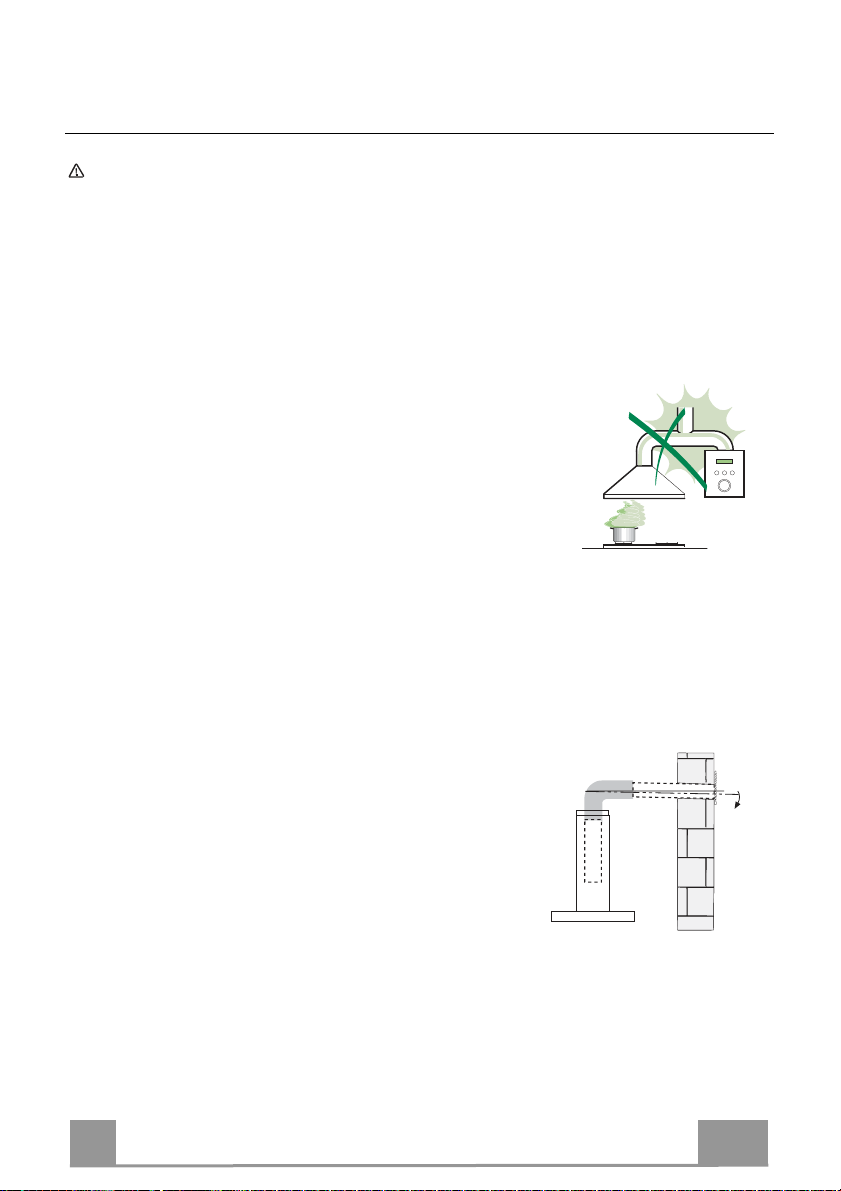
•
Il fabbricante non potrà ritenersi responsabile per eventuali danni risultanti
da un’installazione o utilizzazione impropria.
• La distanza minima di sicurezza tra il piano cottura
e la cappa aspirante è di 650 mm (alcuni modelli
possono essere installati a un’altezza inferiore;
vedere il paragrafo relativo alle dimensioni di lavoro
e all'installazione).
• Controllare che la tensione di rete corrisponda a
quella indicata sulla targa dati applicata all’interno
della cappa.
• Per gli apparecchi di Classe I, controllare che la rete di alimentazione
domestica disponga di un adeguato collegamento a massa.
Collegare l'aspiratore al condotto dei fumi mediante un tubo con diametro
minimo di 120 mm. Il percorso dei fumi deve essere il più corto possibile.
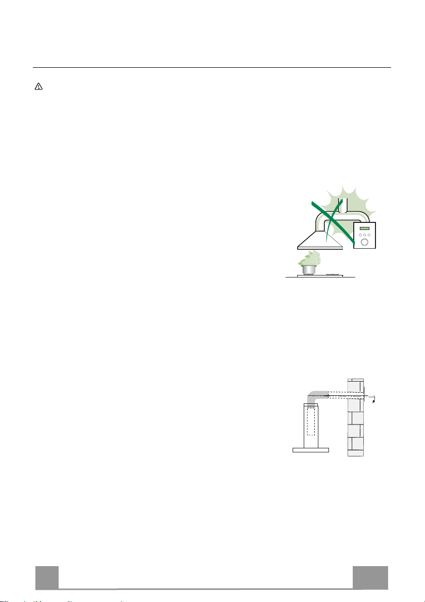
• Non collegare la cappa aspirante ai condotti fumari che trasportano fumi di
combustione (per es. caldaie, camini ecc.).
• Se l’aspiratore è utilizzato in combinazione con
apparecchi non elettrici (per es. apparecchi a gas),
deve essere garantito un sufficiente grado di
aerazione nel locale per impedire il ritorno di flusso
dei gas di scarico. La cucina deve avere un'apertura
comunicante direttamente con l'esterno per garantire
l'afflusso di aria pulita. Quando la cappa per cucina è utilizzata in
combinazione con apparecchi non alimentati dalla corrente elettrica, la
pressione negativa nel locale non deve superare 0,04 mbar per evitare che i
fumi vengano riaspirati nel locale dalla cappa.
• In caso di danneggiamento del cavo di alimentazione, occorre farlo sostituire
dal produttore o dal reparto di assistenza tecnica per evitare qualsiasi
rischio.
3
3
Page 4
IT
• Se le istruzioni di installazione del piano cottura a gas specificano una
distanza maggiore di quella sopra indicata, è necessario tenerne conto.
Devono essere rispettate tutte le normative riguardanti lo scarico dell'aria.
• Usare solo viti e minuteria di tipo idoneo per la cappa.
Avvertenza: la mancata installazione delle viti o dei dispositivi di fissaggio in
conformità alle presenti istruzioni può comportare rischi di scosse elettriche.
• Collegare la cappa all'alimentazione di rete mediante un interruttore bipolare
con distanza tra i contatti di almeno 3 mm.
USO
•
La cappa aspirante è progettata esclusivamente per l’uso domestico allo
scopo di eliminare gli odori dalla cucina.
• Non usare mai la cappa per scopi diversi da quelli per cui è stata progettata.
• Non lasciare mai fiamme alte sotto la cappa quando è in funzione.
• Regolare l'intensità della fiamma in modo da dirigerla esclusivamente verso
il fondo del recipiente di cottura, assicurandosi che non ne avvolga i lati.
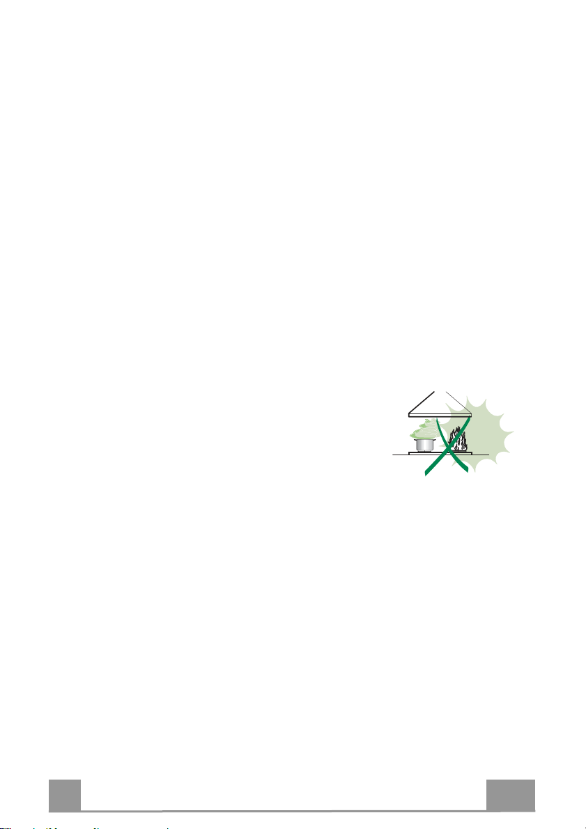
• Le friggitrici devono essere costantemente
controllate durante l’uso: l’olio surriscaldato
potrebbe incendiarsi.
• Non cuocere al flambé sotto la cappa: si potrebbe
sviluppare un incendio.
• Questo apparecchio può essere utilizzato da
bambini di età non inferiore a 8 anni e da persone con ridotte capacità psicofisico-sensoriali o con esperienza e conoscenze insufficienti, purché
attentamente sorvegliati e istruiti su come utilizzare in modo sicuro
l'apparecchio e sui pericoli che ciò comporta. Assicurarsi che i bambini non
giochino con l'apparecchio. Pulizia e manutenzione da parte dell'utente non
devono essere effettuate da bambini, a meno che non siano sorvegliati.
4
4
Page 5
IT
• “ ATTENZIONE: le parti accessibili possono diventare molto calde durante
l’uso degli apparecchi di cottura ”.
MANUTENZIONE
• Spegnere o scollegare l’apparecchio dalla rete di alimentazione prima di
qualunque operazione di pulizia o manutenzione.
• Pulire e/o sostituire i filtri dopo il periodo di tempo specificato (pericolo di
incendio).
• I filtri antigrasso devono essere puliti ogni 2 mesi di funzionamento o più
frequentemente in caso di utilizzo molto intenso e possono essere lavati in
lavastoviglie.
• Il filtro al carbone attivo non è lavabile né è rigenerabile e deve essere
sostituito ogni 4 mesi di funzionamento circa o più frequentemente in caso di
utilizzo molto intenso.
• Pulire la cappa utilizzando un panno umido e un detergente liquido neutro.
Il simbolo
può essere smaltito come un normale rifiuto domestico. Il prodotto da smaltire
deve essere conferito presso un apposito centro di raccolta per il riciclaggio
dei componenti elettrici ed elettronici. Assicurandosi che questo prodotto sia
smaltito correttamente, si contribuirà a prevenire potenziali conseguenze
negative per l’ambiente e per la salute che potrebbero altrimenti derivare dal
suo smaltimento inadeguato. Per informazioni più dettagliate sul riciclaggio di
questo prodotto, contattare il Comune, il servizio locale di smaltimento rifiuti
oppure il negozio dove è stato acquistato il prodotto.
sul prodotto o sulla sua confezione indica che il prodotto non
5
5
Page 6
IT
650 min.
200
100
ø150
698 - 898
190
240
30
9055
r 58
492
360
min 560
max 760
10
11
17
12e
1
7.1
7.2.1
12a 11
12a
12e
12d
2.1
2.2
2
8b
8a
15
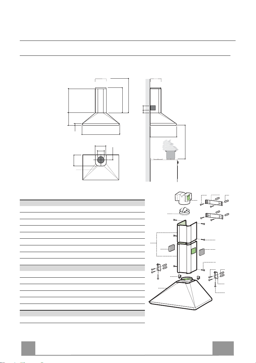
CARATTERISTICHE
Componenti
Rif. Q.tà Componenti di Prodotto
1 1 Corpo Cappa completo di: Comandi, Luce, Filtri
2 1 Camino Telescopico formato da:
2.1 1 Camino Superiore
2.2 1 Camino Inferiore
8a 1 Griglia direzionata Destra
8b 1 Griglia direzionata Sinistra
10 1 Flangia con valvola
15 1 Raccordo uscita Aria
17 2 Boccole Fissaggio Camino Inferiore
Rif. Q.tà Componenti di Installazione
7.1 2 Staffe Fissaggio Corpo Cappa
7.2.1 2 Staffe Fissaggio Camino Superiore
11 8 Tasselli
12a 8 Viti 4,2 x 44,4
12c 6 Viti 2,9 x 9,5
12d 2 Viti M4 x 25
Q.tà Documentazione
1 Libretto Istruzioni
Ingombro
6
6
Page 7
IT
H 175
X
1÷2
650 min.
7.2.1
7.1
120
120
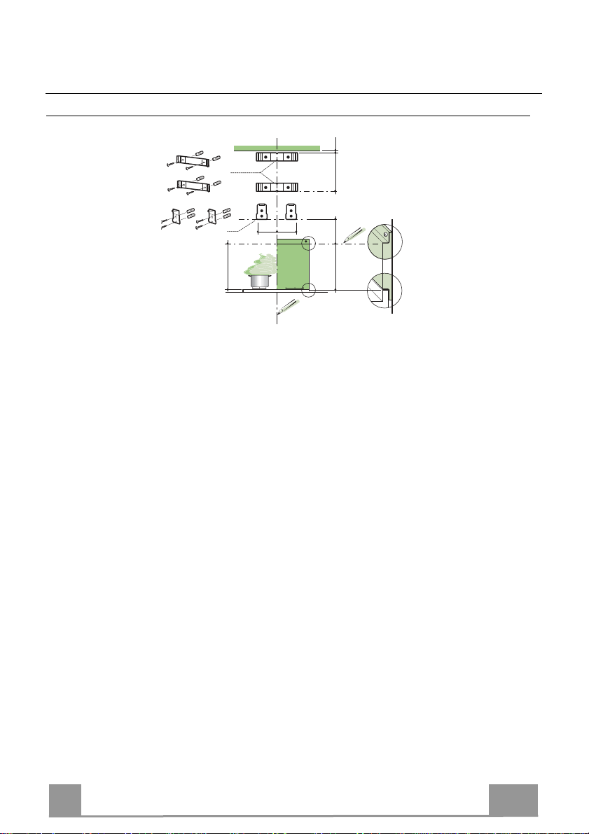
INSTALLAZIONE
Foratura Parete e Fissaggio Staffe
Tracciare sulla Parete:
• una linea Verticale fino al soffitto o al limite superiore, al centro della zona prevista per il
montaggio della Cappa;
• una linea Orizzontale a: 650 mm min. sopra il Piano di Cottura, per installazione senza
Fondale; alla quota H (H = altezza della parte in vista del Fondale), per installazione con
Fondale.
• Appoggiare come indicato la Staffa 7.2.1 a 1-2 mm dal soffitto o dal limite superiore,
allineando il suo centro (intagli) sulla linea Verticale di riferimento.
• Segnare i centri dei Fori della Staffa.
• Appoggiare come indicato la Staffa 7.2.1 a X mm sotto la prima staffa (X = altezza Camino
Superiore in dotazione), allineando il suo centro (intagli) sulla linea Verticale di riferimento.
• Segnare i centri dei Fori della Staffa.
• Appoggiare come indicato, la Staffa 7.1 a 120 mm dalla linea Verticale di riferimento, e
175mm sopra la linea Orizzontale di riferimento.
• Segnare i centri dei Fori della Staffa.
• Ripetere questa operazione dalla parte opposta
FONDALE (OPZIONALE)
Il Fondale va montato prima di montare il Corpo Cappa e, se si desidera fissarlo alla parete sia
superiormente che inferiormente, è necessario montarlo alla giusta altezza, prima del
montaggio delle basi. Essendo questa operazione complessa va effettuata solamente
dall’installatore della cucina o da personale competente che conosca tutte le dimensioni finali
dei mobili.
Limitandosi al solo fissaggio superiore, procedere come segue:
• Appoggiare il Fondale sulla base inserendo la faldina inferiore tra il piano superiore e la
parete, centrandolo sulla linea Verticale di riferimento.
• Segnare i centri dei due fori della faldina superiore.
• Forare ø 8 mm i punti segnati.
• Inserire i tasselli 11 nei fori.
• Fissare le Staffe, utilizzando le Viti 12a (4,2 x 44,4) in dotazione.
• Fissare il Fondale, se presente, utilizzando le Viti 12a (4,2 x 44,4) in dotazione.
7
7
Page 8
IT
Montaggio Corpo Cappa
12.d
7.1
10
ø 150
15
• Avvitare sulle Staffe 7.1, le 2 Viti 12d in dotazione.
• Agganciare il Corpo Cappa alle Staffe 7.1, centrandolo sulla
linea verticale.
• Agire sulle Viti 12d, dal sotto della Cappa, per livellare il
Corpo Cappa.
Connessioni
USCITA ARIA VERSIONE ASPIRANTE
Per installazione in Versione Aspirante collegare la Cappa alla
tubazione di uscita per mezzo di un tubo rigido o flessibile la cui
scelta è lasciata all'installatore.
Collegamento tubo ø 150
• Inserire la Flangia con valvola 10 ø 150 sull’Uscita del Corpo
Cappa.
• Fissare il tubo con adeguate fascette stringitubo. Il materiale
occorrente non è in dotazione.
• Togliere eventuali Filtri Antiodore al Carbone attivo.
USCITA ARIA VERSIONE FILTRANTE
• Applicare a pressione il Raccordo Uscita Aria 15 sull’Uscita
del Corpo Cappa.
• Assicurarsi della presenza del Filtro Antiodore al Carbone
attivo.
8
8
Page 9
IT
1
12e
17
8b
2.1
2.2
2
8a
7.2.1
12e
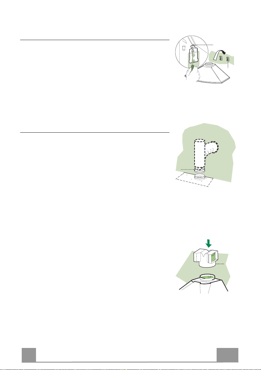
CONNESSIONE ELETTRICA
• Collegare la Cappa all’Alimentazione di Rete interponendo un
Interruttore bipolare con apertura dei contatti di almeno 3 mm.
• Rimuovere i Filtri antigrasso (vedi par. “Manutenzione”) e
assicurarsi che il connettore del Cavo di alimentazione sia
correttamente inserito nella presa dell’Aspiratore
Montaggio Camino
Camino superiore
• Allargare leggermente le due falde laterali, agganciarle dietro
le Staffe 7.2.1 e richiuderle fino a battuta.
• Fissare lateralmente alle Staffe con 4 Viti 12c (2,9 x 9,5) in
dotazione.
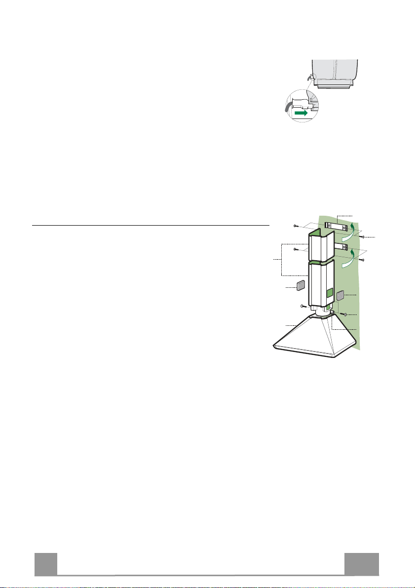
Camino inferiore
• Inserire le Boccole 17 nella parte superiore del Corpo Cappa,
ruotandole di 90° in senso orario fino a battuta.
• Allargare leggermente le due falde laterali del Camino,
agganciarle tra il Camino superiore e la parete e richiuderle
fino a battuta.
• Fissare lateralmente la parte inferiore alle Boccole predisposte,
con 2 Viti 12c (2,9 x 9,5) in dotazione.
• Per la Versione Filtrante applicare le Griglie direzionate 8a 8b nelle apposite sedi, in modo che i simboli direzionali
risultino orientati verso l’alto e il fronte della Cappa.
Assicurarsi inoltre che risultino inserite correttamente nel
Raccordo 15.
9
9
Page 10

IT
1
1
1
0
1
0
2
3
L
M
V
USO
L Luci Accende e spegne l’Impianto di Illuminazione.
M Motore Accende e spegne il motore Aspirazione.
V Velocità Determina la velocità di esercizio:
1. Velocità minima, adatta ad un ricambio d’aria continuo particolarmente
silenzioso, in presenza di pochi vapori di cottura.
2. Velocità media, adatta alla maggior parte delle condizioni d’uso, dato
l’ottimo rapporto tra portata d’aria trattata e livello sonoro.
3. Velocità massima, adatta a fronteggiare le massime emissioni di vapore
di cottura, anche per tempi prolungati.
10
Page 11
IT
1
A
B
MANUTENZIONE
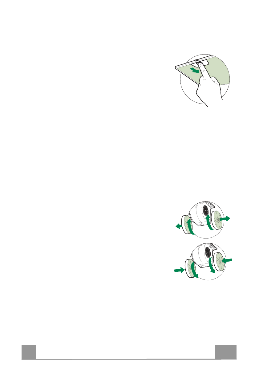
Filtri antigrasso
PULIZIA FILTRI ANTIGRASSO METALLICI AUTOPORTANTI
• Sono lavabili anche in lavastoviglie, e necessitano di essere
lavati ogni 2 mesi circa di utilizzo o più frequentemente, per un
uso particolarmente intenso.
• Togliere i Filtri uno alla volta, spingendoli verso la parte
posteriore del gruppo e tirando contemporaneamente verso il
basso.
• Lavare i Filtri evitando di piegarli e lasciarli asciugare prima di
rimontarli.
• Rimontarli facendo attenzione a mantenere la maniglia verso la
parte visibile esterna.
Filtri antiodore al Carbone attivo (Versione Filtrante)
Il Filtro antiodore al Carbone attivo non è lavabile e non è
rigenerabile, va sostituito ogni 4 mesi circa di utilizzo o più
frequentemente, per un uso particolarmente intenso.
SOSTITUZIONE
• Togliere i Filtri antigrasso.
• Rimuovere i Filtri antiodore al Carbone attivo saturi, come
indicato (A).
• Montare i nuovi Filtri, come indicato (B).
• Rimontare i Filtri antigrasso.
11
Page 12
IT
1
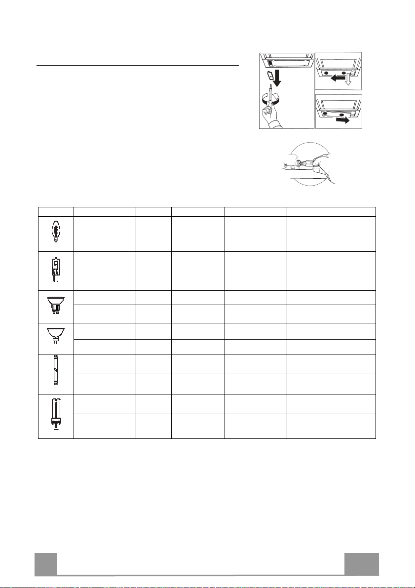
Illuminazione
SOSTITUZIONE LAMPADE
Lampade alogene da 28W/40W
• Togliere i terminali metallici che fissano la
plafoniera.
• Far scorrere la plafoniera verso un lato, fino a
liberare l’estremità opposta. Abbassare leggermente
l’estremità libera e farla scorrere fino a liberarla
totalmente.
• Svitare la Lampada e sostituirla con una nuova di
uguali caratteristiche.
• Rimontare la plafoniera in sequenza inversa.
Lampada Assorbimento (W) Attacco Voltaggio (V) Dimensione (mm) Codice ILCOS
28 E14 220 – 240 104 x 35
20 G4 12 33 x 9 HSG/C/UB-20-12-G4
35 GU10 230 51 x 50,7 HAGS-35-230-GU10-51/40
50 GU10 230 51 x 50,7 HAGS-35-230-GU10-51/20
20 GU4 12 40 x 35 HRGS-20-12-GU4-35/30
20 GU5.3 12 46 x 51 HRGS-20-12-GU5.3-50/10
16 G13 95 720 x 26
18 G13 57 589,8 x 26
9 G23
11 G23
60 (lampada)
220-240 (starter)
91 (lampada)
220-240 (starter)
167 x 28 FSD-9/27/1B-I-G23
235,8 x 28 FSD-11/40/1B-I-G23
HSGSB/C/UB-28-220/240-E14
FD--16/40/1B-E--G13--26/720
FD--18/40/1B--E--G13--26/600
12
Page 13
EN 1
RECOMMENDATIONS AND SUGGESTIONS
2°
The Instructions for Use apply to several versions of this appliance.
Accordingly, you may find descriptions of individual features that do not
apply to your specific appliance.
INSTALLATION
• The manufacturer will not be held liable for any damages resulting from
incorrect or improper installation.
• The minimum safety distance between the cooker top
and the extractor hood is 650 mm (some models can
be installed at a lower height, please refer to the
paragraphs on working dimensions and installation).
• Check that the mains voltage corresponds to that
indicated on the rating plate fixed to the inside of the
hood.
• For Class I appliances, check that the domestic
power supply guarantees adequate earthing.
Connect the extractor to the exhaust flue through a pipe of minimum
diameter 120 mm. The route of the flue must be as short as possible.
Do not connect the extractor hood to exhaust ducts carrying combustion
•
fumes (boilers, fireplaces, etc.).
• If the extractor is used in conjunction with nonelectrical appliances (e.g. gas burning
appliances), a sufficient degree of aeration must
be guaranteed in the room in order to prevent the
backflow of exhaust gas. The kitchen must have
an opening communicating directly with the open
air in order to guarantee the entry of clean air.
When the cooker hood is used in conjunction with
appliances supplied with energy other than electric, the negative pressure in
the room must not exceed 0,04 mbar to prevent fumes being drawn back
into the room by the cooker hood.
•
In the event of damage to the power cable, it must be replaced by the
manufacturer or by the technical service department, in order to prevent any
risks.
13
Page 14

EN
1
• If the instructions for installation for the gas hob specify a greater distance
specified above, this has to be taken into account. Regulations concerning
the discharge of air have to be fulfilled.
• Use only screws and small parts in support of the hood.
Warning: Failure to install the screws or fixing device in accordance with
these instructions may result in electrical hazards.
• Connect the hood to the mains through a two-pole switch having a contact
gap of at least 3 mm.
USE
•
The extractor hood has been designed exclusively for domestic use to
eliminate kitchen smells.
• Never use the hood for purposes other than for which it has been designed.
• Never leave high naked flames under the hood when it is in operation.
• Adjust the flame intensity to direct it onto the bottom of the pan only, making
sure that it does not engulf the sides.
• Deep fat fryers must be continuously monitored
during use: overheated oil can burst into flames.
• Do not flambè under the range hood; risk of fire.
• This appliance can be used by children aged from
8 years and above and persons with reduced
physical, sensory or mental capabilities or lack of
experience and knowledge if they have been given supervision or instruction
concerning use of the appliance in a safe way and understand the hazards
involved. Children shall not play with the appliance. Cleaning and user
maintenance shall not be made by children without supervision.
14
Page 15

EN 1
• “CAUTION: Accessible parts may become hot when used with cooking
appliances.”
MAINTENANCE
• Switch off or unplug the appliance from the mains supply before carrying out
any maintenance work.
• Clean and/or replace the Filters after the specified time period (Fire hazard).
• The Grease filters must be cleaned every 2 months of operation, or more
frequently for particularly heavy usage, and can be washed in a dishwasher.
• The Activated charcoal filter is not washable and cannot be regenerated,
and must be replaced approximately every 4 months of operation, or more
frequently for particularly heavy usage.
• Clean the hood using a damp cloth and a neutral liquid detergent.
The symbol
may not be treated as household waste. Instead it shall be handed over to the
applicable collection point for the recycling of electrical and electronic
equipment. By ensuring this product is disposed of correctly, you will help
prevent potential negative consequences for the environment and human
health, which could otherwise be caused by inappropriate waste handling of
this product. For more detailed information about recycling of this product,
please contact your local city office, your household waste disposal service or
the shop where you purchased the product.
on the product or on its packaging indicates that this product
15
Page 16

EN
1
650 min.
200
100
ø150
698 - 898
190
240
30
9055
r 58
492
360
min 560
max 760
10
11
17
12e
1
7.1
7.2.1
12a 11
12a
12e
12d
2.1
2.2
2
8b
8a
15
CHARACTERISTICS
Dimensions
Components
Ref. Q.ty Product Components
1 1 Hood Body complete with: Controls, Light, Blower,
2 1 Telescopic Chimney comprising:
2.1 1 Upper Section
2.2 1 Lower Section
8a 1 Right Air Outlet Grill
8b 1 Left Air Outlet Grill
10 1 Damper
15 1 Air Outlet Connection
17 2 Lower Chimney Fixing Bush
Ref. Q.ty Installation Components
7.1 2 Hood Body Fixing Brackets
7.2.1 2 Upper Chimney Section Fixing Brackets
11 8 Wall Plugs
12a 8 Screws 4.2 x 44,4
12c 6 Screws 2.9 x 9.5
12d 2 Screws M4 x 25
Q.ty Documentation
1 Instruction Manual
Filters
16
Page 17

EN 1
INSTALLATION
H 175
X
1÷2
650 min.
7.2.1
7.1
120
120
Wall drilling and bracket fixing
W
all marking:
• Draw a vertical line on the supporting wall up to the ceiling, or as high as practical, at the
centre of the area in which the hood will be installed.
• Draw a horizontal line at 650 mm above the hob for installation without the back panel, or at
height H (height of the visible part of the panel) for installation with the back panel.
• Place bracket 7.2.1 on the wall as shown about 1-2 mm from the ceiling or upper limit,
aligning the centre (notch) with the vertical reference line.
• Mark the wall at the centres of the holes in the bracket.
• Place bracket 7.2.1 on the wall as shown at X mm below the first bracket (X = height of the
upper chimney section supplied), aligning the centre (notch) with the vertical line.
• Mark the wall at the centres of the holes in the bracket.
• Place bracket 7.1 as shown 120 mm from the vertical reference line and 175 mm above the
horizontal reference line.
• Mark the centres of the holes in the bracket.
• Repeat this operation on the other side.
REAR PANEL (OPTIONAL)
The Rear Panel must be fitted before fixing the hood body and, if it is to be fixed at both top
and bottom, must be fitted at the correct height prior to installing the bases. As this operation is
rather complex, it should be carried out either by the kitchen installer or a qualified person
who knows the final dimensions of the units.
For fixing at the top only, proceed as follows:
• Rest the back panel on the base, inserting the lower plate between the upper surface and the
wall, centring it on the vertical reference line.
• Mark the centres of the two holes in the upper plate.
• Drill ø 8 mm holes at all the centre points marked.
• Insert the wall plugs 11 in the holes.
• Fix the brackets using the screws 12a (4.2 x 44.4 ) provided.
• Fix the back panel (where present) using the screws 12a (4.2 x 44.4 ) provided.
17
Page 18

EN
1
12.d
7.1
10
ø 150
15
Mounting the hood body
• Screw the two screws 12d supplied onto the brackets 7.1.
• Hook the hood body onto the bracket 7.1, centring it around
the vertical line.
• Use the adjusting screws 12d underneath the hood to level the
hood body.
Connections
DUCTED VERSION AIR EXHAUST SYSTEM
When installing the ducted version, connect the hood to the
chimney using either a flexible or rigid pipe the choice of which
is left to the installer.
To install a ø 150
• To install the dumper 10 ø 150.
• Fix the pipe in position using sufficient pipe clamps (not
supplied).
• Remove any activated charcoal filters.
RECIRCULATION VERSION AIR OUTLET
• Push fit the air outlet fitting 15 onto the air outlet of the hood
body.
• Ensure that the activated charcoal filters have been inserted.
18
Page 19

EN
1
1
12e
17
8b
2.1
2.2
2
8a
7.2.1
12e
ELECTRICAL CONNECTION
• Connect the hood to the mains through a two-pole switch
having a contact gap of at least 3 mm.
• Remove the grease filters (see paragraph Maintenance) being
sure that the connector of the feeding cable is correctly inserted
in the socket placed on the side of the fan.
Chimney assembly
Upper chimney section
• Slightly widen the two sides of the upper chimney and hook
them behind the brackets 7.2.1, making sure that they are
properly housed.
• Secure the sides to the brackets using the 4 screws 12e (2,9 x
9,5) supplied.
Lower exhaust flue
• Insert the lower flue fixing bush 17 in the top of the hood body
and rotate it 90° clockwise as far as it will go.
• Slightly widen the two sides of the chimney and hook them
between the upper chimney section and the wall, making sure
that they are properly housed.
• Secure the sides of the bottom section to the bushes provided
using the 2 screws 12c (2,9 x 9,5) supplied.
• On the recirculation version, fit the directional grids 8a – 8b in
their housings making sure that the directional symbols are
towards the top and front of the hood. Also make sure that they
are correctly inserted in the outlet connection piece 15.
19
Page 20

EN
2
1
1
0
1
0
2
3
L
M
V
USE
L Light Switches the lighting system on and off
M Motor Switches the extractor motor on and off
V Speed Sets the operating speed of the extractor:
1. Low speed, used for a continuous and silent air change in the presence of
light cooking vapour.
2. Medium speed, suitable for most operating conditions given the optimum
treated air flow/noise level ratio.
3. Maximum speed, used for eliminating the highest cooking vapour
emission, including long periods.
20
Page 21

EN
2
A
B
MAINTENANCE
Grease filters
CLEANING METAL SELF- SUPPORTING GREASE FILTERS
• The filters must be cleaned every 2 months of operation, or
more frequently for particularly heavy usage, and can be
washed in a dishwasher.
• Remove the filters one at a time by pushing them towards the
back of the group and pulling down at the same time.
• Wash the filters, taking care not to bend them. Allow them to
dry before refitting.
• When refitting the filters, make sure that the handle is visible
on the outside.
Activated charcoal filter (Recirculation version)
These filters are not washable and cannot be regenerated, and
must be replaced approximately every 4 months of operation, or
more frequently with heavy usage.
REPLACING THE ACTIVATED CHARCOAL FILTER
• Remove the metal grease filters
• Remove the saturated activated charcoal filter as shown (A).
• Fit the new filters (B).
• Replace the metal grease filters.
21
Page 22

EN
2
Lighting
LIGHT REPLACEMENT
28W/40W incandescent light.
• Remove the metal terminals fixing the light cover.
• Slide the light cover to the right until the left hand is
free. Lower it slightly and slide it to the left to free it
completely.
• Unscrew the bulbs and replace them with new ones
having the same characteristics.
• Replace the lighting support in reverse order.
Lamp Power (W) Socket Voltage (V) Dimension (mm) ILCOS Code
28 E14 220 – 240 104 x 35
20 G4 12 33 x 9 HSG/C/UB-20-12-G4
35 GU10 230 51 x 50,7 HAGS-35-230-GU10-51/40
50 GU10 230 51 x 50,7 HAGS-35-230-GU10-51/20
20 GU4 12 40 x 35 HRGS-20-12-GU4-35/30
20 GU5.3 12 46 x 51 HRGS-20-12-GU5.3-50/10
16 G13 95 720 x 26
18 G13 57 589,8 x 26
9 G23
11 G23
60 (lamp)
220-240 (starter)
91 (lamp)
220-240 (starter)
167 x 28 FSD-9/27/1B-I-G23
235,8 x 28 FSD-11/40/1B-I-G23
HSGSB/C/UB-28-220/240-E14
FD--16/40/1B-E--G13--26/720
FD--18/40/1B--E--G13--26/600
22
Page 23

FR
2
2°
CONSEILS ET SUGGESTIONS
Les instructions pour l’utilisation se réfèrent aux différents modèles de cet
appareil. Par conséquent, certaines descriptions de caractéristiques
particulières pourraient ne pas appartenir spécifiquement à cet appareil.
INSTALLATION
•
En aucun cas le fabricant ne peut être tenu pour responsable d’éventuels
dommages dus à une installation ou à une utilisation impropre.
• La distance de sécurité minimum entre le plan de
cuisson et la hotte aspirante est de 650 mm (certains
modèles peuvent être installés à une hauteur inférieure ;
voir le paragraphe concernant les dimensions de travail
et l’installation).
• Assurez-vous que la tension de votre secteur correspond
à celle indiquée sur la plaque des données appliquée à
l’intérieur de la hotte.
• Pour les appareils de Classe I, s’assurer que l’installation électrique de votre
intérieur dispose d’une mise à la terre adéquate.
Relier l’aspirateur au conduit de cheminée avec un tube d’un diamètre minimum
de 120 mm. Le parcours des fumées doit être le plus court possible.
• Ne pas relier la hotte aspirante aux conduits de cheminée qui acheminent les
fumées de combustion (par exemple de chaudières, de cheminées, etc.).
• Si vous utilisez l’aspirateur en combinaison avec des
appareils non électriques (par ex. appareils à gaz), vous
devez garantir un degré d’aération suffisant dans la pièce,
afin d’empêcher le retour du flux des gaz de sortie. La
cuisine doit présenter une ouverture communiquant
directement vers l’extérieur pour garantir l’amenée d’air
propre. Si vous utilisez la hotte de cuisine en combinaison avec des appareils
non alimentés à l’électricité, la pression négative dans la pièce ne doit pas
dépasser 0,04 mbar afin d’éviter que la hotte ne réaspire les fumées dans la
pièce.
• Si le cordon d’alimentation est endommagé, veuillez le faire remplacer par le
fabricant ou par un service après-vente agréé pour éviter tout risque d’accident.
23
Page 24

FR 2
• Si les instructions d’installation du plan de cuisson à gaz spécifient une
distance supérieure à celle indiquée ci-dessus, veuillez impérativement en
tenir compte. Toutes les normes concernant l’évacuation de l’air doivent être
respectées.
• Utiliser exclusivement des vis et des petites pièces du type adapté pour la
hotte.
Attention : toute installation des vis et des dispositifs de fixation non
conforme aux présentes instructions peut entraîner des risques de
décharges électriques.
• Brancher la hotte à l’alimentation de secteur avec un interrupteur bipolaire
ayant une ouverture des contacts d’au moins 3 mm.
UTILISATION
• Cette hotte aspirante a été conçue exclusivement pour un usage
domestique, dans le but d’éliminer les odeurs de cuisine.
• Ne jamais utiliser la hotte pour des objectifs différents de ceux pour lesquels
elle a été conçue.
• Ne jamais laisser un feu vif allumé sous la hotte lorsque celle-ci est en
fonction.
• Régler l’intensité du feu de manière à l’orienter exclusivement vers le fond
de la casserole, en vous assurant qu’il ne déborde pas sur les côtés.
• Contrôler constamment les friteuses durant leur
utilisation : l’huile surchauffée risque de s’incendier.
• Ne pas flamber des mets sous la hotte : sous risque
de provoquer un incendie.
• Cet appareil n’est pas destiné à être utilisé par des
enfants d’un âge inférieur à 8 ans, ni par des personnes dont les capacités
physiques, sensorielles ou mentales sont diminuées ou qui ont une
expérience et des connaissances insuffisantes, à moins que ces enfants ou
ces personnes ne soient attentivement surveillés et instruits sur la manière
d’utiliser cet appareil en sécurité et sur les dangers que cela comporte.
ssurez-vous que les enfants ne jouent pas avec cet appareil. Le nettoyage
A
et l’entretien de la part de l’utilisateur ne doivent pas être effectués par des
enfants, à moins que ce ne soit sous la surveillance d’une personne
responsable.
24
Page 25

FR
2
• ATTENTION : les parties accessibles peuvent devenir très chaudes durant
l’utilisation des appareils de cuisson.
ENTRETIEN
•
Avant d’effectuer toute opération de nettoyage et d’entretien, éteindre ou
débrancher l’appareil du secteur.
• Nettoyer et/ou remplacer les filtres après le délai indiqué (danger
d’incendie).
• Nettoyer les filtres à graisse tous les 2 mois de fonctionnement ou plus
souvent en cas d’utilisation particulièrement intense. Ces filtres peuvent être
lavés au lave-vaisselle.
• Le filtre à charbon actif ne peut être ni lavé ni régénéré et il doit être
remplacé environ tous les 4 mois de fonctionnement ou plus souvent en cas
d’utilisation particulièrement intense.
• Nettoyer la hotte avec un chiffon humide et un détergent liquide neutre.
Le symbole marqué sur le produit ou sur son emballage indique que ce
produit ne peut pas être éliminé comme déchet ménager normal. Lorsque ce
produit doit être éliminé, veuillez le remettre à un centre de collecte prévu pour
le recyclage du matériel électrique et électronique. En vous assurant que cet
appareil est éliminé correctement, vous participez à prévenir des
conséquences potentiellement négatives pour l'environnement et pour la
santé, qui risqueraient de se présenter en cas d’élimination inappropriée. Pour
toute information supplémentaire sur le recyclage de ce produit, contactez
votre municipalité, votre déchetterie locale ou le magasin où vous avez acheté
ce produit.
25
Page 26

FR
2
650 min.
200
100
ø150
698 - 898
190
240
30
9055
r 58
492
360
min 560
max 760
10
11
17
12e
1
7.1
7.2.1
12a 11
12a
12e
12d
2.1
2.2
2
8b
8a
15
CARACTERISTIQUES
Encombrement
Composants
Réf. Q.té Composants de Produit
1 1 Corps Hotte équipé de : Commandes, Lumière, Groupe
2 1 Cheminée Télescopique formée par :
2.1 1 Cheminée Supérieure
2.2 1 Cheminée Inférieure
8a 1 Grille en Direction Droite Sortie Air
8b 1 Grille en Direction Gauche Sortie Air
10 1 Buse avec clapet
15 1 Raccord Sortie Air
17 2 Bagues Fixation Cheminée Inférieure
Réf. Q.té Composants pour l’installation
7.1 2 Brides Fixation Corps Hotte
7.2.1 2 Brides Fixation Cheminée Supérieure
11 8 Chevilles
12a 8 Vis 4,2 x 44,4
12c 6 Vis 2,9 x 9,5
12d 2 Vis M4 x 25
Q.té Documentation
1 Manuel d’instructions
Ventilateur, Filtres
26
Page 27

FR
2
H 175
X
1÷2
650 min.
7.2.1
7.1
120
120
INSTALLATION
Perçage Paroi et Fixation Brides
Tracer sur la paroi :
• une ligne verticale allant jusqu’au plafond ou à la limite supérieure, au centre de la zone
prévue pour le montage de la hotte.
• une ligne horizontale à 650 mm min. au-dessus du plan de cuisson pour installation sans
embases :à la cote H (H = hauteur de la partie en vue de l’embase), en cas d’installation avec
embase.
• Poser comme indiqué une bride 7.2.1 sur la paroi à 1-2 mm du plafond ou de la limite
supérieure, en alignant son centre (découpes) sur la ligne verticale de repère.
• Marquer les centres des trous de la bride.
• Poser comme indiqué la bride 7.2.1 à X mm sous la première bride (X = hauteur cheminée
supérieure fournie), en alignant son centre (découpes) sur la ligne verticale de repère.
• Marquer les centres des trous de la bride.
• Poser comme indiqué, la bride 7.1 à 120 mm de la ligne verticale de repère, et 175 mm audessus de la ligne horizontale de repère.
• Marquer les centres des trous de la bride.
• Répéter cette opération sur le côté opposé.
FIXATION EMBASE (SI FOURNIE)
L’Embase doit être montée avant d’installer le corps de la hotte et si l'on souhaite la fixer au
mur par le haut ou par le bas, il est nécessaire de la monter à la juste hauteur avant de monter
les bases. Comme il s’agit d’une opération complexe, elle doit être confiée à l’installateur de la
cuisine ou à un personnel compétent ayant pris connaissance de toutes les dimensions finales
des meubles.
En se limitant à la fixation supérieure, procéder comme suit :
• Poser l’embase sur la base en insérant l’intercalaire inférieur entre le plan supérieur et la
paroi, en le centrant par rapport à la ligne verticale de repère.
• Marquer les centres des deux trous de l’intercalaire supérieur.
• Percer de ø 8 mm tous les points marqués.
• Insérer les chevilles 11 dans les trous.
• Fixer les brides en utilisant les vis 12a (4,2 x 44,4) fournies.
• Si présente, fixer l’embase, en utilisant les vis 12a (4,2 x 44,4) fournies.
27
Page 28

FR
2
12.d
7.1
10
ø 150
15
Montage Corps Hotte
• Visser sur les brides 7.1 les 2 vis 12d fournies.
• Accrocher le corps hotte aux brides 7.1, en le centrant sur la
ligne verticale.
• Agir sur les vis 12d, par le dessous de la hotte pour en niveler
le corps.
Branchements
SORTIE AIR VERSION ASPIRANTE
En cas d’installation en version aspirante, brancher la hotte à la
tuyauterie de sortie via un tube rigide ou flexible au choix de
l’installateur.
Raccordement du tuyau de ø 150
• Positionner la bride 10 ø 150 sur la sortie du corps de la hotte ;
• Fixer le tuyau à l’aide de colliers serre-tube appropriés. Le
matériel nécessaire n’est pas fourni.
• Retirer les éventuels Filtres Anti-odeur au Charbon actif.
SORTIE AIR VERSION FILTRANTE
• Appliquer par pression le raccord sortie air 15 sur
la sortie du corps de la hotte.
• S’assurer de la présence des filtres anti-odeur au
charbon actif.
28
Page 29

FR
2
1
12e
17
8b
2.1
2.2
2
8a
7.2.1
12e
BRANCHEMENT ELECTRIQUE
• Brancher la hotte sur le secteur en interposant un interrupteur
bipolaire avec ouverture des contacts d’au moins 3 mm.
• Enlever les filtres à graisse (voir § "Entretien") et s'assurer que
le connecteur du câble d'alimentation soit bien branché dans la
prise du diffuseur.
Montage Cheminée
Cheminée supérieure
• Elargir légèrement les deux bords latéraux, et les accrocher
derrière les brides 7.2.1 ; refermer jusqu’à la butée.
• Fixer latéralement aux brides, à l’aide des 4 vis 12e (2,9 x 9,5)
fournies.
Cheminée inférieure
• Insérer les bagues 17 dans la partie supérieure du corps de la
hotte en les tournant de 90° dans le sens des aiguilles d’une
montre jusqu’à la butée.
• Elargir légèrement les deux bords latéraux de la Cheminée et
les accrocher entre la Cheminée supérieure et la paroi ;
refermer jusqu’à la butée.
• Fixer latéralement la partie inférieure aux bagues prévues à cet
effet, à l’aide des 2 vis 12c fournies.
• Pour la version filtrante, appliquer les grilles en direction 8a –
8b dans les logements appropriés, pour que les symboles de
direction soient orientés vers le haut et la partie avant de la
hotte. S’assurer également qu’elles soient bien insérées dans
les raccord 15.
29
Page 30

FR 3
UTILISATION
1
1
0
1
0
2
3
L
M
V
L Lumières Allume et éteint l’éclairage.
M Moteur Allume et éteint le moteur aspiration
V Vitesses Détermine les vitesses d’exploitation ainsi subdivisées:
1.Vitesse minimale, pour un rechange d’air permanent particulièrement
silencieux en cas de faibles vapeurs de cuisson.
2.Vitesse moyenne pour la plupart des conditions d’utilisation, étant donné
le rapport optimal entre débit d’air traité et niveau sonore.
3.Vitesse maximum, pour faire face aux émissions maximum de vapeur de
cuisson, même pendant des temps prolongés .
30
Page 31

FR
3
A
B
ENTRETIEN
Filtres anti-graisse
NETTOYAGE FILTRES ANTI-GRAISSE METALLIQUES AUTOPORTEURS
• Lavables au lave-vaisselle, ils doivent être lavés environ tous
les 2 mois d’emploi ou plus fréquemment en cas d’emploi
particulièrement intense.
• Retirer les filtres l’un après l’autre, en les poussant vers la
partie arrière du groupe et en tirant simultanément vers le bas.
• Laver les filtres en évitant de les plier et les laisser sécher avant
de les remonter.
• Remonter les filtres en veillant à ce que la poignée reste vers la
partie visible externe
Filtre anti-odeur (Version filtrante)
Il ne sont pas lavables ni régénérables, il faut les remplacer au
moins tous les 4 mois d’emploi ou plus fréquemment en cas
d’emploi particulièrement intense.
REMPLACEMENT FILTRE AU CHARBON ACTIF
• Retirer les filtres anti-graisse métalliques.
• Retirer les filtres anti-odeur au charbon actif saturés, comme
indiqué (A).
• Monter les nouveaux filtres (B).
• Remonter le filtres anti-graisse métalliques.
31
Page 32

FR
3
Remonter le plafonnier, en exécutant la séquence à
Éclairage
REMPLACEMENT DES AMPOULES
Ampoules halogènes de 28W/40W
• Retirer les crochets métalliques qui fixent le
plafonnier.
• Faire coulisser le plafonnier sur un côté, jusqu’à
dégager l’extrémité opposée. Baisser légèrement
l’extrémité qui est dégagée et faire coulisser cette
dernière jusqu’à ce qu’elle soit totalement dégagée.
• Dévisser l’Ampoule puis la remplacer par une neuve,
possédant les mêmes caractéristiques.
•
rebours.
Ampoule Absorption (W) Culot Voltage (V) Dimensions (mm) Code ILCOS
28 E14 220 – 240 104 x 35
20 G4 12 33 x 9 HSG/C/UB-20-12-G4
35 GU10 230 51 x 50,7 HAGS-35-230-GU10-51/40
50 GU10 230 51 x 50,7 HAGS-35-230-GU10-51/20
20 GU4 12 40 x 35 HRGS-20-12-GU4-35/30
20 GU5.3 12 46 x 51 HRGS-20-12-GU5.3-50/10
16 G13 95 720 x 26
18 G13 57 589,8 x 26
9 G23
11 G23
60 (ampoule)
220-240 (starter)
91 (ampoule)
220-240 (starter)
167 x 28 FSD-9/27/1B-I-G23
235,8 x 28 FSD-11/40/1B-I-G23
HSGSB/C/UB-28-220/240-E14
FD--16/40/1B-E--G13--26/720
FD--18/40/1B--E--G13--26/600
32
Page 33

DE 3
EMPFEHLUNGEN UND HINWEISE
2°
Diese Gebrauchsanleitungen beziehen sich auf die verschiedenen Modelle
der Abzugshaube. Darum kann es möglich sein, dass die Beschreibung
bestimmter Merkmale für das vorliegende Gerät nicht zutrifft.
INSTALLATION
• Der Hersteller haftet nicht für etwaige Schäden, die durch die fehlerhafte
Installation oder falschen Gebrauch entstehen könnten.
• Der min. Sicherheitsabstand zwischen Kochfeld
und Abzugshaube beträgt 650 mm (einige Modelle
können auch niedriger installiert werden; siehe
Absatz Installation).
• Kontrollieren Sie, ob die Netzspannung den Daten
des Typenschilds im Innern der Haube entspricht.
• Für Geräte der Klasse I muss kontrolliert werden,
ob das häusliche Versorgungsnetz korrekt geerdet
ist.
Die Absaughaube mit Hilfe eines Rohrs mit einem Mindestdurchmesser von
120 mm mit dem Rauchabzug verbinden. Der Verlauf des Rauchabzugs soll
so kurz wie möglich sein.
Die Abzugshaube darf nicht an einen Schacht angeschlossen werden, in den
•
Rauchgase geleitet werden (z. B. von Heizkessel, Kaminen, usw.).
• Falls in dem Raum neben dem Abzug auch nicht
mit Strom betriebene Geräte (zum Beispiel
Gasgeräte) eingesetzt werden, muss für eine
ausreichende Belüftung gesorgt werden, damit der
Rückfluss der Abgase verhindert wird. Die Küche
muss eine direkte Öffnung nach Außen aufweisen,
damit ein ausreichender Luftaustausch
gewährleistet wird. Wird die Abzugshaube
zusammen mit nicht mit Strom betriebenen Geräte eingesetzt, darf der
Unterdruck im Raum 0,04 mbar nicht überschreiten, damit die Abgase nicht
wieder angesaugt werden.
• Schadhafte Kabel müssen durch den Hersteller oder vom Kundendienst
ausgewechselt werden, damit jedes Risiko ausgeschlossen wird.
33
Page 34

DE
3
• Falls die Montageanweisungen für die gasbetriebene Kochmulde einen
größeren Abstand vorschreiben, als der oben angegebene, muss diese
Vorgabe befolgt werden. Es sind sämtliche Abluftvorschriften zu beachten.
• Nur für die Abzugshaube geeignete Schrauben und Kleinteile verwenden.
Achtung: Werden die Schrauben und Befestigungselemente nicht
entsprechend der vorliegenden Anleitungen verwendet, besteht
Stromschlaggefahr.
• Die Abzugshaube mittels zweipoligem Schalter mit einer Öffnung der
Kontakte von mindestens 3 mm an das Netz anschließen.
GEBRAUCH
•
Die Abzugshaube wurde ausschließlich für den häuslichen Gebrauch
entwickelt, um Kochdünste zu beseitigen.
• Die Haube darf nur für die ihr zugedachten Zwecke benutzt werden.
• Unter der eingeschalteten Haube keine offenen Flammen benutzen.
• Die Flamme so regulieren, dass sie nicht über den Boden des Kochgeschirrs
hinausreicht.
• Fritteusen müssen während des Gebrauchs
ständig überwacht werden: überhitztes Öl könnte
sich entzünden.
• Auf keinen Fall unter der Haube flambieren:
Brandgefahr.
• Kinder ab 8 Jahren und Personen mit
eingeschränkten physischen, sensorischen oder psychischen Fähigkeiten,
oder mit mangelnden Erfahrungen oder Kenntnissen dürfen nicht mit dem
Gerät umgehen, es sei denn, sie werden von einer für ihre Sicherheit
verantwortlichen Person beaufsichtigt oder angeleitet. Sicherstellen, dass
Kinder nicht mit dem Gerät herumspielen können. Reinigungs- und
Wartungsarbeiten dürfen nicht von unbeaufsichtigten Kindern durchgeführt
werden.
34
Page 35

DE
3
• ACHTUNG: Die zugänglichen Teile können während des Gebrauchs der
Kochgeräte sehr heiß werden.
WARTUNG
•
Vor Reinigungs- oder Wartungsarbeiten am Gerät, muss dieses
ausgeschaltet und spannungslos gemacht werden.
• Die Filter stets nach den angegebenen Intervallen reinigen oder
auswechseln (Brandgefahr).
• Die Fettfilter sind alle 2 Monate oder bei intensiver Nutzung öfter zu reinigen
und können in der Spülmaschine gespült werden.
• Der Aktivkohlefilter ist weder waschbar, noch regenerierbar und muss bei
normalem Betrieb zirka alle 4 Monate oder auch öfter ausgewechselt
werden, je nach Intensität des Gebrauchs.
• Die Haube mit einem feuchten Lappen und einem neutralen
Reinigungsmittel abwischen.
Das Symbol am Produkt oder auf der Verpackung weist darauf hin, dass
das Gerät nicht als normaler Hausmüll entsorgt werden darf. Das ausrangierte
Gerät muss vielmehr bei einer speziellen Sammelstelle für elektrische und
elektronische Geräte abgegeben werden. Mit der vorschriftsmäßigen
Entsorgung des Gerätes trägt der Benutzer dazu bei, schädliche
Auswirkungen auf Umwelt und Gesundheit zu vermeiden. Weitere
Informationen zum Recycling dieses Produktes können bei der zuständigen
Behörde, der örtlichen Abfallbeseitigung oder bei dem Händler, der das Gerät
verkauft hat, eingeholt werden.
35
Page 36

DE
3
650 min.
200
100
ø150
698 - 898
190
240
30
9055
r 58
492
360
min 560
max 760
10
11
17
12e
1
7.1
7.2.1
12a 11
12a
12e
12d
2.1
2.2
2
8b
8a
15
CHARAKTERISTIKEN
Platzbedarf
Komponenten
Pos. St. Produktkomponenten
1 1 Haubenkörper mit Schaltern, Beleuchtung,
2 1 Teleskopkamin bestehend aus:
2.1 1 oberer Kaminteil
2.2 1 unterer Kaminteil
8a 1 Luftleitgitter Luftaustritt rechts
8b 1 Luftleitgitter Luftaustritt links
10 1 Flansch mit Ruckstauklappe
15 1 Luftaustritt-Anschlussstück
17 2 Befestigungsbuchsen unter Kaminteil
Pos. St. Montagekomponenten
7.1 2 Befestigungsbügel Haubenkörper
7.2.1 2 Befestigungsbügel oberer Kaminteil
11 8 Dübel
12a 8 Schrauben 4,2 x 44,4
12c 6 Schrauben 2,9 x 9,5
12d 2 Schrauben M4 x 25
St. Dokumentation
1 Bedienungsanleitung
Gebläsegruppe, Filtern
36
Page 37

DE
3
H 175
X
1÷2
650 min.
7.2.1
7.1
120
120
MONTAGE
Bohren der Befestigungslöcher und Fixieren der Befestigungsbügel
Nachstehende Linien an die Wand zeichnen:
• eine vertikale Linie bis zur Decke oder oberen Begrenzung, und zwar in der Mitte des
Bereiches, in dem die Haube montiert werden soll;
• eine horizontale Linie: mit einem minimalen Abstand von 650 mm zur Kochmulde bei
Montage ohne Rückwandpaneel; mit einem Abstand H (Höhe des sichtbaren Teils des
Rückwandpaneels) bei Montage mit Rückwandpaneel.
• Einen Bügel 7.2.1 zirka 1-2 mm unter der Decke oder oberen Begrenzung an die Wand
legen und seinen Mittelpunkt (Einschnitte) auf die vertikale Bezugslinie ausrichten.
• Die Mitte der beiden Bügellöcher an der Wand markieren.
• Den zweiten Bügel 7.2.1 an die Wand legen, wobei ein Abstand X mm vom oberen Bügel
einzuhalten ist (X = Höhe des jeweiligen oberen Kaminteils); den Mittelpunkt (Einschnitte)
auf die vertikale Bezugslinie ausrichten.
• Die Mitte der Bügellöcher an der Wand markieren.
• Einen der beiden Bügel 7.1 120 mm von der vertikalen Bezugslinie und 175 mm oberhalb
der horizontalen Bezugslinie auflegen.
• Die Mittelpunkte der Bügelbohrungen an der Wand markieren.
• Gleichermaßen an der gegenüberliegenden Seite vorgehen.
RÜCKWANDPANEEL (OPTION)
Das Rückwandpaneel wird vor der Dunstabzugshaube montiert; falls es sowohl an der Oberwie auch Unterseite befestigt werden soll, muss es vor Montage der Unterschränke in korrekter
Höhe fixiert werden.Da es sich hierbei um einen komplexen Arbeitsschritt handelt, muss
dieser Vorgang vom Kücheninstallateur bzw. auf jeden Fall von erfahrenem Personal
durchgeführt werden, das die Endmaße der Küchenmöbel kennt.
Wird das Rückwandpaneel nur oben fixiert, ist wie nachstehend vorzugehen:
• Das Paneel auf den Unterschrank stellen und den unteren Rand zwischen Arbeitsfläche und
Wand schieben, wobei die Rückwand auf die vertikale Bezugslinie auszurichten ist.
• Die Bohrungen an der oberen Kante kennzeichnen.
• Mit einem Bohrer ø 8 mm die markierten Punkte bohren.
• Die Dübel 11 in die Bohrungen einfügen.
• Die Bügel mit den mitgelieferten Schrauben 12a (4,2 x 44,4) fixieren.
• Falls ein Rückwandpaneel vorhanden ist, dieses mit den mitgelieferten Schrauben 12a (4,2 x
44,4) fixieren.
37
Page 38

DE
3
12.d
7.1
10
ø 150
15
Montage des Haubenkörpers
• Bei den Bügeln 7.1 die 2 mitgelieferten Schrauben 12d
einschrauben.
• Den Haubenkörper bei den Haltebügeln 7.1 einhängen und auf
die vertikale Linie ausrichten.
• Mit Hilfe der Schrauben 12d vom Haubenunteren her den
Haubenkörper ausrichten.
Anschlüsse
ANSCHLUSS IN ABLUFTVERSION
Bei Abluftbetrieb kann die Haube vom Installateur wahlweise
mittels Rohr oder Schlauch an die Außenrohrleitung
angeschlossen werden.
Anschlussrohres ø 150
• Den Flansch mit Rückstauklappe 10 ø 150 anbringen.
• Das Rohr mit geeigneten Rohrschellen fixieren. Das hierzu
erforderliche Material wird nicht mitgeliefert.
• Eventuell vorhandene Aktivkohlefilter entnehmen.
ANSCHLUSS IN UMLUFTVERSION
• Das Anschlussstück 15 beim Luftaustritt des Haubenkörpers
eindrücken.
• Sicherstellen, dass der Aktivkohle-Geruchsfilter vorhanden ist.
38
Page 39

DE 3
ELEKTROANSCHLUSS
1
12e
17
8b
2.1
2.2
2
8a
7.2.1
12e
• Bei Anschluss der Haube an das Stromnetz muss ein
zweipoliger Schalter mit einem Öffnungsweg von mindestens
3 mm zwischengeschaltet werden.
• Entfernen Sie die Fettfilter (s. Abschnitt „Wartung“) und
versichern Sie sich, daß die Kabelverbindung in die Steckdose
des Gebläses einwandfrei eingesteckt wird.
Kaminmontage
Oberer Kaminteil
• Die beiden seitlichen Schenkel leicht auseinanderbiegen, hinter
den Bügeln 7.2.1 einhängen und bis zum Anschlag wieder
schließen.
• Bei den Bügeln mit Hilfe der 4 mitgelieferten Schrauben 12e
(2,9 x 9,5) fixieren.
Unterer Kaminteil
• Die Buchsen 17 an der Oberseite des Haubenkörpers einfügen
und bis zum Anschlag im Uhrzeigersinn um 90° drehen.
• Die beiden seitlichen Schenkel des Kaminteils leicht
auseinanderbiegen, zwischen dem oberen Kaminteil und der
Wand einhängen und bis zum Anschlag wieder schließen.
• Den unteren Kaminteil an der Seite bei den entsprechenden
Buchsen mit 2 der mitgelieferten Schrauben 12c fixieren.
• Bei Umluftbetrieb die Luftleitgitter 8a – 8b in die
entsprechenden Sitze einsetzen, wobei darauf zu achten ist,
dass die Richtungssymbole nach oben und vorne weisen.
Sicherstellen, dass sie korrekt beim Luftaustritt-Anschluss 15
eingerastet sind.
39
Page 40

DE
4
1
1
0
1
0
2
3
L
M
V
BEDIENUNG
L Beleuch. Schaltet die Beleuchtung ein und aus
M Motor Schaltet den Gebläsemotor ein und aus
V Geschw. Steuert folgende Geschwindigkeitsstufen:
1.geringste Gebläsestufe, diese Stufe ist für einen ständigen und besonders
leisen Luftaustausch bei geringer Kochdunstentwicklung geeignet;
2.mittlere Gebläsestufe, eignet sich aufgrund des guten Verhältnisses
zwischen Fördervolumen und Geräuschentwicklung für die meisten
Anwendungssituationen;
3.höchste Gebläsestufe, eignet sich für starke Kochdunstentwicklung, auch
über längere Zeit hin.
40
Page 41

DE 4
WARTUNG
A
B
Fettfilter
SELBSTTRAGENDER METALLFETTFILTER REINIGUNG
• Sie müssen nach 2-monatigem Betrieb bzw. bei starkem
Einsatz auch häufiger gereinigt werden, was im Geschirrspüler
möglich ist.
• Die Filter nacheinander aushaken, indem sie auf die Rückseite
der Gruppe geschoben und gleichzeitig nach unten gezogen
werden.
• Die Filter reinigen (darauf achten, sie nicht zu verbiegen) und
vor der Remontage trocknen lassen.
• Bei der Remontage ist darauf zu achten, dass sich der Griff auf
der sichtbaren Außenseite befindet.
Geruchsfilter (Umluftbetrieb)
Sie können weder gewaschen noch wiederverwendet werden und
sind alle 4 Betriebsmonate bzw. bei starkem Einsatz auch
häufiger auszutauschen.
AUSTAUSCHEN DER AKTIVKOHLE FILTER
• Die Metallfettfilter entnehmen.
• Den gesättigten Aktivkohle-Geruchsfilter wie gezeigt
entfernen (A).
• Die neuen Filter wie gezeigt montieren (B).
• Die Metallfettfilter wieder montieren.
• Die Kohlefilter können mit dem Hausmüll entsorgt werden.
41
Page 42

DE 4
Beleuchtung
ERSETZEN DER LAMPEN
Halogenlampen 28W/40W
• Die Metallenden, mit denen die Lampenabdeckung
befestigt ist, entfernen.
• Die Lampenabdeckung zur Seite gleiten lassen, bis
die gegenüberliegende Seite frei liegt. Die freie Seite
leicht nach unten ziehen und die Lampenabdeckung
ganz herausziehen.
• Die Lampe herausdrehen und durch eine neue mit
identischen Eigenschaften ersetzen.
• Die Lampenabdeckung in umgekehrter Reihenfolge
wieder montieren.
Lampe Leistung (W) Fassung Spannung (V) Größe (mm) ILCOS-Code
28 E14 220 – 240 104 x 35
20 G4 12 33 x 9 HSG/C/UB-20-12-G4
35 GU10 230 51 x 50,7 HAGS-35-230-GU10-51/40
50 GU10 230 51 x 50,7 HAGS-35-230-GU10-51/20
20 GU4 12 40 x 35 HRGS-20-12-GU4-35/30
20 GU5.3 12 46 x 51 HRGS-20-12-GU5.3-50/10
16 G13 95 720 x 26
18 G13 57 589,8 x 26
9 G23
11 G23
60 (Lampe)
220-240 (Starter)
91 (Lampe)
220-240 (Starter)
167 x 28 FSD-9/27/1B-I-G23
235,8 x 28 FSD-11/40/1B-I-G23
HSGSB/C/UB-28-220/240-E14
FD--16/40/1B-E--G13--26/720
FD--18/40/1B--E--G13--26/600
42
Page 43

436003985_ver3
 Loading...