


KTS1625
Digital Multifunction Tester
Users Manual


KTS1625
Digital Multifunction Tester
Users Manual
September 2011, Rev.1
©2011 Amprobe Test Tools.
All rights reserved. Printed in China
English

Limited Warranty and Limitation of Liability
Your Amprobe product will be free from defects in material and workmanship for 1 year from
the date of purchase, unless local laws require otherwise. This warranty does not cover fuses,
disposable batteries or damage from accident, neglect, misuse, alteration, contamination, or
abnormal conditions of operation or handling. Resellers are not authorized to extend any other
warranty on Amprobe’s behalf. To obtain service during the warranty period, return the product
with proof of purchase to an authorized Amprobe Test Tools Service Center or to an Amprobe
dealer or distributor. See Repair Section for details. THIS WARRANTY IS YOUR ONLY REMEDY.
ALL OTHER WARRANTIES - WHETHER EXPRESS, IMPLIED OR STAUTORY - INCLUDING IMPLIED
WARRANTIES OF FITNESS FOR A PARTICULAR PURPOSE OR MERCHANTABILITY, ARE HEREBY
DISCLAIMED. MANUFACTURER SHALL NOT BE LIABLE FOR ANY SPECIAL, INDIRECT, INCIDENTAL
OR CONSEQUENTIAL DAMAGES OR LOSSES, ARISING FROM ANY CAUSE OR THEORY. Since
some states or countries do not allow the exclusion or limitation of an implied warranty or of
incidental or consequential damages, this limitation of liability may not apply to you.
Repair
All test tools returned for warranty or non-warranty repair or for calibration should be
accompanied by the following: your name, company’s name, address, telephone number, and
proof of purchase. Additionally, please include a brief description of the problem or the service
requested and include the test leads with the meter. Non-warranty repair or replacement charges
should be remitted in the form of a check, a money order, credit card with expiration date, or a
purchase order made payable to Amprobe® Test Tools.

PFC PSC
KTS1625 Digital Multifunction Tester
1
2
3
6 7 5
LCD Display
1
Function Buttons (F1, F2, F3, F4)
2
F1: Display Backlight
Continuity Buzzer
0° or 180° phase selection for RCD test
L - N or L - PE loop test
F2: Lock Test
RCD 30s count-down test
Sine wave selection for RCD test
Half-wave selection for RCD test
F3: Test Lead resistance zero
Test data recall for RCD Auto Test
F4: I
n selection for RCD Test
4
Test Button
3
Rotary Switch
4
COM / N Terminal(Black)
5
L / V / Ω Terminal(Red)
6
PE terminal(Green)
7

PFC PSC
Screen Display
1 2 3 4 5 6 7 8 9
16 20
17
18
19
L – N or L – PE Loop Test
1
Presence of Hazardous
2
Voltages
Continuity Buzzer
3
Over-temperature! Allow
4
the Tester to cool down
Sine wave signal (AC Current)
5
Half-wave Signal
6
30s Count-down Test
7
Test Lock for Continuous
8
Measurement
Test Data Recall For RCD
9
Auto Test
Test Lead Resistance Zero
10
RCD Test at X1/2, X1, X5
11
RCD Auto Test
12
10
Fault Voltage Between N and
13
PE Conductor Exceeds 50V
RCD Ramp Test
14
Low Battery Indicator
15
Noise Between N and PE Conductor
16
RCD Test Phase Selection 0° / 180°
17
Over-temperature! Allow the
18
Tester to cool down
Wiring correction Check for Loop
19
and RCD Test
Prospective Earth Fault Current
20
Prospective Short-Circuit Current
21
DC Voltage
22
AC Voltage
23
12 13 14 15
23 22
21

KTS1625 Digital Multifunction Tester
CONTENTS
SYMBOL .................................................................................................................2
SAFETY INFORMATION .........................................................................................2
UNPACKING AND INSPECTION .............................................................................3
FEATURES ...............................................................................................................4
MAKING MEASUREMENT .....................................................................................5
Rotary Switch Positions ....................................................................................5
Function Buttons ..............................................................................................6
Measuring AC Voltage .....................................................................................8
Measuring Insulation Resistance .....................................................................9
Measuring Continuity ......................................................................................11
Measuring Loop Impedance ............................................................................14
Measuring RCD Tripping Time .........................................................................17
Using Test Probe with Remote Test Button ....................................................23
SPECIFICATION ......................................................................................................24
MAINTENANCE ......................................................................................................28
BATTERY AND FUSE REPLACEMENT .....................................................................28
1

SYMBOLS
SAFETY INFORMATION
The Meter complies with:
EN 61010-1 3nd Edition, Category III 300 Volts, Pollution degree 2,
IP40 as per EN 60529
EN 61010-2-030
EN 61010-2-31 for test leads
EMC EN 61326-1
EN 61557-1/-2/-3/-4/-6/10
Measurement Category III (CAT III) is for measurements performed in the
building installation. Examples are measurements on distribution boards,
circuit- breakers, wiring, including cables, bus-bars, junction boxes, switches,
socket-outlets in the fixed installation, and equipment for industrial use
and some other equipment, for example, stationary motors with permanent
connection to the fixed installation.
Caution ! Risk of electric shock.
Caution! Refer to the explanation in this Manual
The equipment is protected by double insulation or
reinforced insulation
Do not use in distribution systems with voltages higher
than 440V
Earth (Ground)
Battery
Complies with European Directives
Do not dispose of this product as unsorted municipal waste.
Contact a qualified recycler.
2

CENELEC Directives
The instruments conform to CENELEC Low-voltage directive 2006/95/EC and
Electromagnetic compatibility directive 2004/108/EC
Warning: Read Before Using
• To avoid possible electrical shock or personal injury, follow these
instructions and use the Meter only as specied in this manual.
• Do not use the Tester or test leads if they appear damaged, or if the
Meter is not operating properly. If in doubt, have the Tester serviced.
• Always use the proper function and range for measurements.
• Before rotating the function range selection switch, disconnect test
probe from circuit under test.
• Verify the Tester’s operation by measuring on a known voltage source.
• Do not apply more than the rated voltage, as marked on the Tester,
between the test probe or between any test probe and earth ground.
• Use the Tester with caution for voltages above 30 Vac rms, 42 Vac peak,
or 60 Vdc. These voltages pose electrical shock hazards.
• Disconnect circuit power and discharge all high-voltage capacitors before
testing insulation resistance and continuity.
• Do not use the Tester around explosive gas or vapor.
• When using the test leads, keep your ngers behind the nger guards.
• Remove test leads from the Tester and turn off the Tester before opening
the Tester case or battery door.
• Do not use in distribution systems with voltages higher than 440V AC or
DC.
• Follow the operating manual at all times when using the Tester and have
the operating manual in an easily accessible place.
• Incorrect operation will cause incident and damage to the Tester.
• Before and after testing, conrm that no hazardous voltage at the
terminals presents.
3

UNPACKING AND INSPECTION
Your shipping carton should include:
1 KTS1625 Digital Multifunction Tester
1 3-Wire Mains Test Cord Set
1 Test Lead set (Red, Black, Green)
1 Test Probe set (Red, Black, Green)
1 Alligator clip set (Red, Black, Green)
1 Red Test probe with Remote Test Button
8 1.5V alkaline AA battery
1 Users manual
1 Strap
1 Carrying case
If any of the items are damaged or missing, return the complete package to
the place of purchase for an exchange.
FEATURES
Safety and performance are two most critical requirements for every electrical
system. The quality of insulation, properly working grounding system and
active protection are “must have” to assure safety of the people, electrical
systems and buildings against electrocution, fire, and other equipment
damage. They are critical to prevent loss of productivity due to power
interruption.
Robin-Amprobe KTS1625 is a multifunction installation tester measuring
various parameters of the electrical system to provide complete safety
analysis. It features loop impedance measurements as well as measurement of
continuity and insulation resistance of motors, transformers or wires, testing of
RCD systems, measuring voltage and frequency.
• Insulation Resistance Functions:
- Tests insulation of wires, cables, transformers and electrical motors
- Selectable test voltages 250V, 500V and 1000V
- Test button lock for dielectric absorption ration test
- Automatic discharge of test object after completion of measurement
4

• Continuity Functions:
- Earth continuity @ 200mA
• Line / Loop Impedance Functions:
- Prospective Fault Current
- Prospective Short-Circuit current
• RCD Functions:
- Phase switch selection 0° and 180° for positive and negative semi-cycle testing
- RAMP Slope measurement
- 30 Seconds Countdown Measurement
- RCD Half-Wave test
- Auto RCD test
• Designed to allow testing to BS7671 IEE 17th Edition regulations
• Voltage and Frequency Measurements
• Instant correct wiring status check
• Dual measurement result display
• Large, backlit display
• Low Battery Indication
• Safety CAT III 300V
MAKING MEASUREMENT
1. Use the proper function and range for measurements.
2. To avoid possible electrical shock, personal injury or damages to the
Tester, disconnect circuit power and discharge all high-voltage capacitors
before testing insulation resistance and continuity.
3. Connecting test leads:
• Connect PE test lead (green) to the circuit before connecting the live leads;
• After measurement, remove live leads before removing PE test lead
from the circuit
5

Rotary Switch Positions
Switch Position Measurement Function
Volts AC Voltage / Frequency measurement.
250V Insulation Resistance at DC 250V.
Insulation
Continuity Ω Continuity measurement.
Loop
RCD
500V Insulation Resistance at DC 500V.
1000V Insulation Resistance at DC 1000V.
NO TRIP L – PE(PSC) or L – N(PFC) Loop impedance NO TRIP mode
Hi
L – PE Loop Impedance and Prospective Short-Circuit
PSC
Current
Auto Automatic tripping test for unknown RCD.
X ½ Non-Tripping RCD test.
X 1 Tripping RCD test.
X 5 Fast tripping RCD test.
Ramp Test, 50%~110% Default nominal residual
currents (I
Ramp
Increasing by 10%, total 7 steps of residual current.
n).
Function Buttons
TEST Button
Press TEST button to begin selected measurement function on the rotary switch.
F1 Button
Press > 2 sec to turn the display backlight on or off.
Insulation resistance < 2MΩ buzzer will sound. Continuity
test < 20Ω buzzer will sound.
RCD test phase selection (0 or 180 degrees).
L-N/L-PE
Loop Impedance (L-PE) or Line Impedance (L-N)
measurement for NO TRIP mode.
6

F2 Button
“Test Lock” for continuous measurement. Press F2 to enable
Test Lock mode (
press TEST button for continuous measurement. Under Test
Lock mode, TEST button will hold for Dielectric Absorption
Ratio Test (DAR) purpose. DAR value can be calculated by
Riso(1min)/Riso(30s).
To exit Test Lock mode, press F2 or turn rotary switch to
another function position.
Selective mode. A 30 second time delay.
AC current to test type AC (standard AC RCD).
Half-wave current to test type A (pulse-DC sensitive RCD).
Press F2 to select the RCD test-current waveform:
F3 Button
ZERO
RCL
Delayed response to test S-type AC (time delayed AC RCD)
Half-wave current to test type A (pulse-DC sensitive RCD)
Delayed response to S-type A
(time delayed pulse-DC sensitive RCD)
AC current to test type AC (standard AC RCD)
Test Lead / Probe Zeroing. Press F3 to zero the test lead / probe.
Can subtract up to 10Ω of lead resistance. Buzzer audio
warning sound for lead resistance >10 Ω.
Error message and buzzer audio sound for resistance >10 Ω.
Data recall for RCD Auto test. Press F3 to scroll the test results.
symbol is shown on the screen) and
F4 Button
Press F4 to select I
n (RCD current rating 10, 30, 100, 300, or 500 mA).
7

Error message display
PFC
1. Over-temperature: wait while the temperature cools down for next measurement
2. Fault Voltage: Check voltage between N and PE conductor.
Measuring AC Voltage
• To avoid personal injury or damage to the tester, do not apply voltage
higher than 440V.
• Connecting test leads:
- Connect COM test lead (black) to the circuit before connecting the live leads;
- After measurement, remove live leads before removing COM test lead
from the circuit
To measure voltage and frequency:
1. Turn the rotary switch to Volts position.
2. Use red and black (V – COM) terminals for this test. You can use test
leads or 3-wire mains test cord when measuring AC voltage.
The primary display shows the Voltage.
The secondary (smaller digits on the right side) display shows the Frequency.
8

v
V
COM
F1 b u tt on
Figure 1: Measuring AC voltage by test leads
9
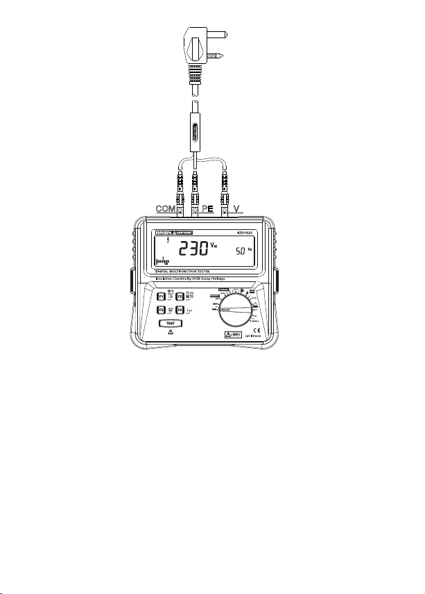
COM PE
V
Figure 2: Measuring AC voltage by 3-wire mains test cord
Measuring Insulation Resistance
• Make sure disconnecting circuit power and de-energize the circuit before test.
• When measuring insulation resistance, make sure test leads are separated
and are not twisted together.
• Do not short circuit two test leads when output DC voltage presents at
the output terminals.
• Do not measure insulation resistance at live high voltage circuit.
• Do not carry out measurement when the battery compartment is open or
accessible.
10

• When the measurement is completed, do not touch the circuit as the
circuit may store energy, which may cause electric shock. Allow time for
circuit to discharge
• Warning buzzer will sound when the Tester detects a voltage >30Vac or
dc. Display shows symbol and the detected voltage.
Figure 3: Tester detects a voltage >30Vac
Figure 4: Tester detects a voltage >30Vdc
To measure voltage and frequency:
1. Turn the rotary switch to Insulation position (250V, 500V, or 1000V).
2. Use the red and black (L – N) terminals for this test with test leads.
3. Press F1 to activate
4. Press F2 to activate Test Lock mode for continuous measurement.
Note: Testing is inhibited if voltage is detected in the circuit under
measurement.
5. Press TEST button to begin measurement.
The primary display shows the insulation resistance.
The secondary (smaller digits on the right side) display shows the actual
test voltage.
, buzzer will sound when resistance < 2MΩ.
11

LN
R
F 1 F 2
Figure 5: Measuring insulation resistance
Measuring Continuity
• Disconnect circuit power and de-energize the circuit before test.
• Do not measure continuity at live high voltage circuit.
• Do not carry out measurement when the battery compartment is open
or accessible.
• Warning buzzer will sound when the Tester detects a voltage >30Vac or
dc. Display shows
symbol and the detected voltage.
12

Figure 6: Tester detects a voltage >30Vac
Figure 7: Tester detects a voltage >30Vdc
To measure continuity:
1. Turn the rotary switch to Continuity position.
2. Use the red and black (Ω – COM) terminals for this test with test leads.
3. Before making a continuity measurement, use ZERO function to zero
the test leads.
Test lead resistance zeroing:
Step 1: Connect test leads to Ω and COM terminals and short-circuit the
test leads/probes.
Step 2: Press and hold F3 (ZERO) button. The measured resistance of
the test leads is shown on the primary display until a beep is heard and
the ZERO annunciator appears. When Display shows 0.00Ω, test lead
resistance zero is complete.
The tester measures test leads / probe resistance, stores the reading in
memory, and subtracts it from readings. The resistance value of test leads
/ probe is saved even when the Tester is switched off. When the next time
you switch on the Tester, you do not need to repeat test lead / probe
zeroing step every time you use the Tester. When using a different set of
test leads / probes, zeroing has to be repeated.
Note: The ZERO function can subtract up to 10Ω of lead resistance.
Warning buzzer audio sound for lead resistance >10 Ω.
13

4. Press TEST button
COM
R
F1 F 2 F3
ZERO
The primary display shows the continuity resistance.
The secondary (smaller digits on the right side) display shows the actual
output DC voltage.
When
symbol on screen, buzzer threshold ≤ 20Ω
Figure 8: Measuring continuity
14

Measuring Loop Impedance
• The Tester is designed for measurement on single phase system only – AC
230V, 50Hz (operating voltage range: AC 230V +10%/-15%, 50Hz).
• Make sure the wiring is correct and the ground wire is reliably connected
earth. The tester displays symbols of “L-PE”, “L-N” and “N-PE” to indicate
the correct wiring connections. Blinking of symbols “L-PE” or “L-N” or
“N-PE” indicates incorrect wiring.
• Make sure the grounding of the socket-outlet is connected to Earth. The
symbol of “L-PE” and “N-PE” on the display means grounding wire is not
connected to earth or not well-connected to earth.
• When measuring the loop impedance/prospective short-circuit current,
make sure line and neutral wires are connected correctly. Pay attention to
the wiring symbols on display.
• Use Volts function to check the circuit voltage before the measurement.
• “HOT” symbol on screen indicates over-temperature. Allow time for the
Tester to cool down for next measurements.
Connecting to the circuit
Correct wiring: “L-PE” and“L-N” symbols are displayed – proceed to test
Incorrect wiring: when wiring symbols are blinking on display – STOP!
Check the wiring connections.
• “L-PE” and “L-N” symbols blinking indicate missing L wiring connection
or incorrect wiring of line conductor
• “L-PE” and “N-PE” symbols blinking indicate missing PE wiring
connection or incorrect wiring of PE conductor
• “L-N” and “N-PE” symbols blinking indicate missing N wiring connection
or incorrect wiring of N conductor
15

N LPE
PFC
F
(NO TRIP only)
(NO TRIP only)
1 button
Figure 9: Measuring Loop by 3-wire mains test cord
16

PE
NEUTRAL
EARTH
PHASE
PFC
N L
Figure 10: Measuring Loop by test leads
Loop Impedance (Line to Protective Earth L-PE)
To measure L-PE loop impedance:
1. Turn the rotary switch to Hi PSC position.
2. Use the red, green and black (L – PE – N) terminals for this test. You can
use test leads or mains test cord when measuring loop impedance.
Check the signs of wiring connection before proceeding test.
3. Press TEST button
The primary display shows the L-PE loop impedance.
The secondary (smaller digits on the right side) display shows PEFC.
17

Measuring loop impedance NO TRIP mode:
To prevent tripping RCDs in the circuit:
• Use the NO TRIP function for loop measurements.
• An RCD with a nominal fault current of 15mA or above will trip.
To measure L-PE loop impedance NO TRIP mode:
1. Turn the rotary switch to NO TRIP position. L-PE symbol on the screen
(upper-left corner) indicates L-PE loop impedance.
2. Use the red, green and black (L – PE – N) terminals for this test. You can
use test leads or mains test cord when measuring loop impedance.
Check the signs of wiring connection before proceeding test.
3. Press TEST button
The primary display shows the L-PE loop impedance.
The secondary (smaller digits on the right side) display shows PFC.
To measure L-N loop impedance NO TRIP mode:
1. Turn the rotary switch to NO TRIP position.
2. Press F1 button to select L-N loop impedance measurement. L-N symbol
displays on the screen (upper-left corner).
3. Use the red, green and black (L – PE – N) terminals for this test. You can
use test leads or mains test cord when measuring loop impedance.
Check the signs of wiring connection before proceeding test.
4. Press TEST button
The primary display shows the L-N loop impedance.
The secondary (smaller digits on the right side) display shows PSC.
Measuring RCD Tripping Time
• The Tester is designed for measurement on single phase system only – AC
230V, 50Hz (operating voltage range: AC 230V +10%/-15%, 50Hz).
• Any test and measurement procedures in circuits equipped with residual current
devices should only be performed after having consulted the operator terminals
(data processing systems, material processing, motors, etc.).
• Equipment, which is connected downstream of a residual current
protective device (RCD) may cause a considerable extension of the
operating time. Examples of such equipment might be connected
capacitors or running motors.
• The protective earth must be free of external voltage for the RCD test.
However if an extraneous voltage is present (>50V fault voltage), the
18

Tester indicates >50V Uf having been generated by the measurement.
The measurement interruption caused by excess of Uf is only generated
by the actual voltage present between the neutral conductor (N) and the
protective earth (E).
• Time-delayed residual current devices trip at nominal residual current
within 130…500ms, for double nominal fault current within 60…200ms.
• Such RCDs are implemented as main residual current protection devices
(please refer to IEC 61008-1) and are marked with the symbol “ S ”.
• At a measuring circuit without probe, available voltages between PE and
earth can influence the measurement.
• Before using the N-conductor as probe check that all neutral points have
low ohm resistance to the main neutral line. A available voltage of the N
conductor to the earth can influence the measurement.
• The measuring function uses the N-conductor as a probe. Check rst
the connection between the neutral point of the distribution system
and earth before the test is started. A possible voltage between the
N-conductor and earth may influence the measurements.
• Leakage currents in current circuits following the RC circuit breaker may
have an influence on the test as well as a voltage between protective
conductor or neutral conductor and ground.
• Attached loads or operating supplies which contains capacitors or
circulating machines can elongate the trip time.
• Measurements may be inuenced by potential elds of other grounding
systems.
• Measurements must be carried out in compliance with the respectively
valid standards and regulations.
• Make sure the wiring is correct and the ground wire is reliably connected
earth. The tester displays symbols of “L-PE”, “L-N” and “N-PE” to indicate
the correct wiring connections. Blinking of symbols “L-PE” or “L-N” or
“N-PE” indicates incorrect wiring.
Connecting to the circuit
Correct wiring: “L-PE” and“L-N” symbols are displayed – proceed to test
Incorrect wiring: when wiring symbols are blinking on display – STOP!
Check the wiring connections.
• “L-PE” and “L-N” symbols blinking indicate missing L wiring connection
or incorrect wiring of line conductor

• “L-PE” and “N-PE” symbols blinking indicate missing PE wiring
PE
F1 button F2 button F4 button
10mA
30mA
100mA
300mA
500mA
10mA
30mA
100mA
300mA
N L
connection or incorrect wiring of PE conductor
• “L-N” and “N-PE” symbols blinking indicate missing N wiring connection
or incorrect wiring of N conductor
Figure 11: Measuring RCD trip time by 3-wire mains test cord
20

PE
NEUTRAL
EARTH
PHASE
N L
Figure 12: Measuring RCD trip time by test leads
To perform Auto RCD test:
1. Turn the rotary switch to AUTO position.
2. Use the red, green and black (L – PE – N) terminals for this test. You can
use test leads or mains test cord when measuring loop impedance.
Check the signs of wiring connection before proceeding test.
3. Press F4 button to select tripping current
10mA, 30mA, 100mA
10mA, 30mA
21

4. Press F2 to select waveform or selective mode (a 30 second time delay)
5. Press TEST button
Auto RCD test automatically performs a sequence of 6 RCD trip time tests
with a single press on TEST button.
Auto RCD test sequence:
½I
n / 0°→ ½I n / 180°→ I n / 0°→ I n / 180°→ 5I n / 0°→ 5 n / 180°
Each time the RCD trips, re-set RCD to continue unfinished the test
sequence until the whole sequence is completed.
When AUTO test is completed, “RCL” symbol is displayed on screen.
Press F3 to display the measurement results. The measurement result is
displayed in the order of the test sequence. Press F3 again to show the
next measurement result.
To measure RCD tripping time (X1/2, X1, X5):
1. Turn the rotary switch to the desired test current multiplier
(X1/2, X1 or X5) position.
Normally X1 is used for this test.
X1/2 for non-tripping test. RCD shall not open.
X1 for tripping test. RCD shall open.
X51 for fast tripping test. RCD shall open.
2. Use the red, green and black (L – PE – N) terminals for this test.
You can use test leads or mains test cord when measuring loop
impedance. Check the signs of wiring connection before proceeding test.
3. Press F4 button to select tripping current
Delayed response to test S-type AC
(time delayed AC RCD)
Half-wave current to test type A
(pulse-DC sensitive RCD)
Delayed response to S-type A
(time delayed pulse-DC sensitive RCD)
AC current to test type AC
(standard AC RCD)
22

X1/2, X1
10mA, 30mA, 100mA, 300mA, 500mA
10mA, 30mA, 100mA, 300mA
X5
10mA, 30mA, 100mA
10mA, 30mA
4. Press F1 button to select test current phase 0° or 180°.
5. Press F2 button to select waveform or selective mode
6. Press TEST button
The primary display shows the L-PE loop impedance.
The secondary (smaller digits on the right side) display shows PFC.
To perform RAMP test:
1. Turn the rotary switch to RAMP position.
2. Use the red, green and black (L – PE – N) terminals for this test. You can
use test leads or mains test cord when measuring loop impedance.
Check the signs of wiring connection before proceeding test.
3. Press F4 button to select tripping current
4. Press F2 to select waveform or selective mode
5. Press TEST button
Delayed response to test S-type AC
(time delayed AC RCD)
Half-wave current to test type A
(pulse-DC sensitive RCD)
Delayed response to S-type A
(time delayed pulse-DC sensitive RCD)
AC current to test type AC
(standard AC RCD)
23

Using Test Probe with Remote Test Button
R
N L
CAT IV 600V
CATI II10 00V
10A
TEST Button
This test probe with remote test button allows users to perform
measurement by pressing TEST button on the probe when both hands are
holding test probes during measurement.
Below measurements can be made by using the test probe with remote test button:
• Continuity
• Insulation resistance
WARNING
Follow the instructions in “Measuring Insulation Resistance” section and
“Measuring Continuity” section before marking measurements.
Figure 13: Testing with test probe with remote test button
24

SPECIFICATION
Ambient temperature: 23°C ±5°C (73.4°F ±9°F); Relative temperature: ≤75%
Accuracy: ±(% of reading + LSD)
Display: maximum reading is 9999.
Over-range indication: maximum reading
Operating Condition: 0°C to +40°C, <85% Relative Humidity
Storage Condition: -20°C to +60°C, <90% Relative Humidity
Dimension (L x W x D): 189 × 167 × 85mm (7.43 x 6.65 x 3.35in)
Weight: approx. 1.3 kg (2.87 lb) with batteries installed
Low Battery warning indication: “
Power Supply: Alkaline Battery 1.5V (AA Battery or equivalent) × 8pcs
The number of possible tests with a fresh set of batteries is >1000.
Fault Voltage detection: 50Vrms.
”
AC Voltage Measurement
Range Resolution Accuracy Overload Protection
0 – 400V 1V
±(5% Rdg +2 LSD)
@ 45 – 65Hz
440Vrms
Insulation Resistance Measurement
DC Test
Voltage
250V
1000V ≥1mA@ 1MΩ
Resolution Test Current Accuracy
≥1mA@ 0.25MΩ
1V
0 to +10%500V ≥1mA@ 0.5MΩ
Measuring Range
(auto ranging)
0.00MΩ – 9.99MΩ 0.01MΩ
100MΩ – 1999MΩ 1MΩ
Note: Buzzer threshold: 2MΩ
Live circuit detection: >30Vac or dc
Resolution Accuracy
25
± (5% Rdg + 5 LSD)10.0MΩ – 99.9MΩ 0.1MΩ

Continuity Measurement
Range
(Auto ranging)
1.99Ω 0.01Ω >4Vdc
199Ω 1Ω >4Vdc
Note: Measuring current (short-circuited) ≥ 200mA
Nominal open-circuit output voltage: 5Vdc
Buzzer threshold: 20Ω
Live circuit detection: >30Vac or dc
Test probe zeroing: can subtract up to 10Ω of lead resistance.
Range Test Voltage Accuracy
± (2% Rdg +5 LSD)19.9Ω 0.1Ω >4Vdc
Loop Impedance Measurement
Operating Rated Voltage: 195 – 253Vac, 45 – 65Hz
Range Resolution Accuracy
Line Impedance
(L-N)
@25A
Loop Impedance
(L-PE)
@25A
Loop impedance
without tripping
@15mA
Prospective Short
Circuit Current
@25 A
Prospective Earth
Fault Current
@25 A
0.01Ω - 1.99Ω
2.0Ω - 19.9Ω
20Ω - 2000Ω
0.01Ω - 1.99Ω
2.0Ω - 19.9Ω
20Ω - 2000Ω
1.00Ω - 1.99Ω
2.0Ω - 19.9Ω
20Ω - 2000Ω
0.00A~1.99A
2.0A~19.9A
20A~199A
200A~1.99kA
2.0kA~26kA
0.00A~1.99A
2.0A~19.9A
20A~199A
200A~1.99kA
2.0kA~26kA
± (5% Rdg +5 LSD)
± (5% Rdg +5 LSD)
± (5% Rdg +12 LSD + Noise
Margin (1.00 - 1.99Ω)
PSC accuracy derived from
measured loop impedance
specification and measured
voltage specification
PFC accuracy derived from
measured loop impedance
specification and measured
voltage specification
26

RCD Measurement
Operating Rated Voltage: 195 – 253Vac, 45 – 65Hz
Function
RCD
AUTO
test
RCD
RAMP
test
X1/2
RCD Test Current Selection
10mA 30mA 100mA 300mA 500mA
√ √ √
√ √
√ √ √ √ √
√ √ √ √ √
√ √ √ √ √
√ √ √ √ √
Accuracy
0% to +10% at
X1 and X5
-10% to 0% @
1/2X
50%~110%
Default nominal
residual currents
(I n). Increasing
by 10%, total 7
steps of residual
current.
-10% to 0%
X1
√ √ √ √ √ 1)
√ √ √ √ √ 1)
√ √ √
X5
√ √ √
Note: 1) Selective mode only.
Function RCD type *
Tripping Time
Measurement Range
X1/2 G 2000ms
X1/2 S 2000ms
X1 G 300ms
X1 S 500ms
X5 G 40ms
X5 S 40ms
0% to +10%
0% to +10%
Accuracy
± (2% Rdg +2 LSD)
27

Note: *G – General, no delay
*S – Time delay
EN 61557 Measurement Range
Function Display Range
Volts
EN 61557-1
Insulation
EN 61557-2
Loop
EN 61557-3
Continuity
EN 61557-4
T, I
EN 61557-6
100Vac – 400Vac,
0.05MΩ - 1000MΩ
0.01Ω - 2000Ω
0.00Ω - 199Ω
T 0ms – 2000ms
N
I
N
/ 100mA / 300mA /
45Hz – 65Hz
Hi Current
NO TRIP
1Ω - 2000Ω
10mA / 30mA
500mA
EN 61557
Measurement Range
Operating Error
10Vac – 400Vac,
45Hz – 65Hz
±(5% + 2 LSD)
0.25MΩ - 1000MΩ
±(5% + 5 LSD)
0.5Ω - 2000Ω
±(5% + 5 LSD)
1Ω - 2000Ω
±(5% + 12 LSD)
0.2Ω - 199Ω
±(2% + 5 LSD)
20ms – 2000ms
±(2% + 2 LSD)
10mA / 30mA /
100mA / 300mA /
500mA
±(10% + 2 LSD)
Nominal Values
U
= 230Vac
N
f = 50Hz
U
= 250/ 500/
N
1000Vdc
I
= 1.0mA
N
U
=230Vac
N
f = 50Hz
Ik=26kA
Uo = 5Vdc (typical)
I
≥ 200mA
N
T = 10 / 30 / 100
/ 300 / 500mA
IN = 10 / 30 / 100
/ 300 / 500mA
28

MAINTENANCE AND REPAIR
If the Tester fails to operate, check battery, test leads, etc., and replace as
necessary.
Double check the followings:
1. Check the battery. Replace the battery immediately when the symbol
” appears on the display.
“
2. Review the operating instructions for possible mistakes in operating
procedure.
Except for the replacement of the battery, repair of the Tester should be
performed only by an Authorized Service Center or by other qualified
instrument service personnel.
The front panel and case can be cleaned with a mild solution of detergent and
water.
Apply sparingly with a soft cloth and allow to dry completely before using. Do
not use aromatic hydrocarbons, Gasoline or chlorinated solvents for cleaning.
BATTERY AND FUSE REPLACEMENT
WARNING
To avoid shock, injury, or damage to the Tester, disconnect test leads/test
cord before opening case.
Replacing BATTERY follow below steps:
1. Disconnect the test lead probe from measuring circuit.
2. Turn the rotary switch to OFF position.
3. Remove the screws from the battery cover and open the battery cover
4. Remove the batteries and replace with 8 x 1.5V Alkaline Batteries (AA or
equivalent). Pay attention to the polarity signs.
5. Put the battery cover back and re-fasten the screw.
29

Battery:1.5V Alkaline Batteries (AA or equivalent).
30

31

• Catalog
• Application notes
• Product specifications
• User manuals
 Loading...