

Page 1

52 Hurricane Way, Norwich, NR6 6JB
Telephone +44(0)1603 256601 (Switchboard)
+44(0)1603 256602 (Sales)
Facsimile +44(0)1603 256603
Page 2

PORTABLE APPLIANCE TESTER
SmartPAT 5500
User Manual
Page 3

Portable Appliance Tester
CONTENTS
INTRODUCTION 2
Warnings and Cautions 2
Technical Specifications 3
Test Summary 5
Controls and Accessories 6
Results 9
INSTALLATION 9
Power Requirements 9
Connections 9
Setting Up 10
OPERATING INSTRUCTIONS 12
TESTING 12
Visual Check 12
Auto Testing 12
Reviewing 16
Storing 16
Storage Type 16
Programming 20
IEC Lead Test 24
Manual Testing 24
FAULT FINDING AND REPAIR 25
Calibration 25
Basic Maintenance 25
GENERAL ENQUIRIES 25
SmartPAT 5500
INTRODUCTION
Thank you for purchasing Robin Portable Appliance
Tester. Please ensure you read and understand
these instructions fully before starting any testing.
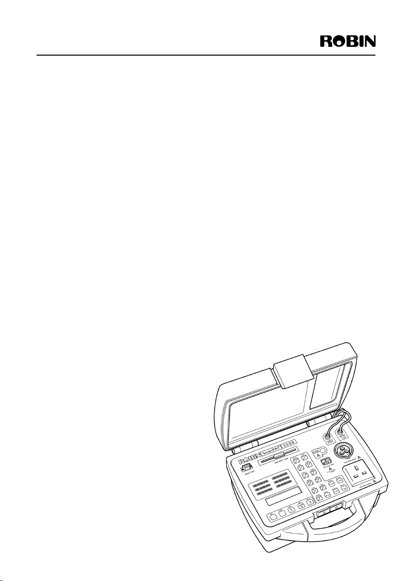
The SmartPAT 5500 is a State of the Art Portable
Appliance Tester (PAT) with automatic testing
capability. It is capable of performing preset earth
bonding, insulation, fuse continuity, run/leakage and
flash voltage tests. The equipment is contained in
a high impact carrying case, see Figure 1. When
opened access is provided to the operating panel,
secured into the base of the case, this panel carries
all the operating switches, connectors, serial port,
floppy disc drive and the results display. The lid of
the case provides a storage space for the cables
associated with the appliance tester.
WARNINGS AND CAUTIONS
Although the equipment has been built to meet
the requirements of the IEC publication 1010,
Safety Requirements for Electronic Measuring
Apparatus, the following warnings and cautions
must be adhered to:
WARNINGS
LETHAL VOLTAGES. THE SmartPAT 5500
CONTAINS HAZARDOUS VOLTAGES,
CORRECT HIGH VOLTAGE HANDLING
PRECAUTIONS,AS LAID DOWN IN THE
ELECTRICITY AT WORK REGULATIONS
1989, MUST BE OBSERVED AT ALL TIMES.
CAUTIONS
EQUIPMENT DAMAGE.
The equipment has been set for a nominal
230V/110V operation, it must never be connected
to a higher voltage.
EQUIPMENT DAMAGE.
The mains supply is never to be connected to the
IEC lead test connection.
ABRASIVE MATERIALS.
Routine Maintenance. Do not use abrasive
materials, metal polish or furniture polish
during cleaning procedures.
TEMPERATURE CONTROL.
Operating and Storage Temperatures below -10°C
may cause permanent damage to the equipment.
DATA STORAGE.
This equipment has the ability to store test
records within an onboard memory.The data
within the memory should not be left to
accumulate over a period of time but should be
downloaded frequently (daily during normal
testing) to a secure storage medium e.g. PC hard
drive or floppy disc. Robin Electronics accepts no
responsibility for lost of stored data due to misuse
of the appliance tester or non-compliance with
the operating instructions.
2
Page 4
SmartPAT 5500
Technical Specifications
The technical specifications of the SmartPAT 5500 are as follows:
Mains input supply
Voltage 100 V to 120 V rms at 50/60 Hz ±10%
207 V to 255 V rms at 50/60 Hz ±10%
Power consumption 30 W maximum (quiescent)
Earth leakage current 3 mA maximum
Display
Type 2 line, 20 characters per line Liquid Crystal Display (LCD)
Character Height 5.5 mm
Character width 3 mm
Viewing Angle ‘6 0’clock’
Contrast Adjustment Fixed
Communications
Format Serial
Data Rate 1200 to 9600 bps (user selectable)
Interface RS232/V24, support for IRDA adapter,
IBM keyboard (through adapter), HP Smartwand
and a Panasonic scanner
Environmental
Storage Temperature -10 to +50°C
Operating Temperature 0 to 40°C (results within calibrated limits)
-10 to 60°C (results may be outside calibrated limits)
Humidity 0 to 90% R-H non condensing
Pollution level II
IP Rating IP51 case closed, IP30 case open
Figure 1 SmartPAT 5500 tester
3
Page 5

SmartPAT 5500
The Technical Specifications of the Tests performed by the SmartPAT 5500 Portable Appliance Tester are
as follows:
Earth Bond
The earth bonding specifications are taken at a nominal mains input supply of 110 V or 235 V rms, unless
otherwise stated.
High Current
Open Circuit Voltage 3 V rms ±10%
Test Current 5 A, 8 A or 26 A ±15% into 0.1 ohm load.
(in-built intelligent current limit)
Display Resolution 0.01 ohm to 19.99 ohm, then shows >20 ohm.
Display Accuracy ±(3% + 4 digits)
Test Duration 10s or 15s to 1 minute, dependent on time test button held down
Business Equipment
Open Circuit Voltage 3 V rms ±10%
Test Current 100 mA +20% -0% at 230 Vrms into 0.5 ohm load.
Display Resolution 0.01 ohm to 19.99 ohm, then shows >20 ohm.
Display Accuracy ±(3% + 4 digits)
Test Duration 10s or 15s to 1 minute, dependent on time test button held down
Pass Threshold 0.1 ohm steps up to 5 ohm then 0.5 ohm steps to 19.99 ohm
(user selectable)
Insulation Test
The earth bonding specifications are taken at a nominal mains input supply of 110 V or 235 V rms, unless
otherwise stated.
Open Circuit Voltage 560 V dc +16%,-0%
Short Circuit Current 3.5 mA ±10%
Current into 500k 1.0 mA minimum
Display Resolution 0 1 to 99.9 Mohm, then 1 to 299 Mohm, >300 Mohm
Display Accuracy ±(5% + 4 digits)
Test Duration 10s or 15s to 1 minute, dependent on time test button held down
Pass Threshold 0.1 Mohm steps to 0.9 Mohm
1 Mohm steps from 1 to 9 Mohm
10 Mohm steps from 10 to 300 Mohm
(user selectable)
Fuse/Load/Leakage Test
Leak
Earth Leakage Current 0.1mA to 9.9mA
Display resolution 0.1mA
Display accuracy ±(5% + 4 digits), capacitive/resistive leakage
Leakage threshold 0.5 to 10 mA in 0.5 mA steps
Abort on leakage > 15 mA
4
Page 6

SmartPAT 5500
Load
Load Measurement 0.1kVA to 3.99kVA
Display Resolution 0.1kVA
Display Accuracy ±(5% + 4 digits), resistive or reactive load
Abort on Surge > 60 A exponential, time constant 50 ms
Abort on Run Current > 13 A (235 V), > 16 A (110 V)
Test Duration 5s to 60s,Terminating immediately
when STOP button pressed.
Flash Test
Open Circuit Voltage 1500Vrms (Class I), 3000vrms (Class II)
Short Circuit Current 5mA at normal mains input
Display Resolution 0.1mA
Display Accuracy ±(5% + 4 digits)
Test Summary
The following statements provide a brief summary of the tests performed by the SmartPat 5500.
Earth bond
Checks the resistance between the Earth pin of the appliance under test and any exposed metalwork on
the appliance.
Insulation
Checks the resistance of the insulation between the Earth pin of the appliance under test cable plug or
the earth bond crocodile clip, to the Live and Neutral pins of the appliance (pins are connected together
within the SmartPAT 5500 for this test).
Fuse/Load/Leakage
A low dc fuse test is performed first to check the continuity of the fuse in the appliance under test, by
checking the resistance between the Live and Neutral pins of the appliance cable plug. On completion of
the fuse test an earth leakage test and a VoltAmpere test is performed with the appliance under test being
powered up.
Flash
A 1.5kV rms voltage is applied between the earth and live/neutral pins of a class I appliance and 3 kV rms
voltage between the flash probe and the live/neutral pins of a class II appliance.
5
Page 7
SmartPAT 5500
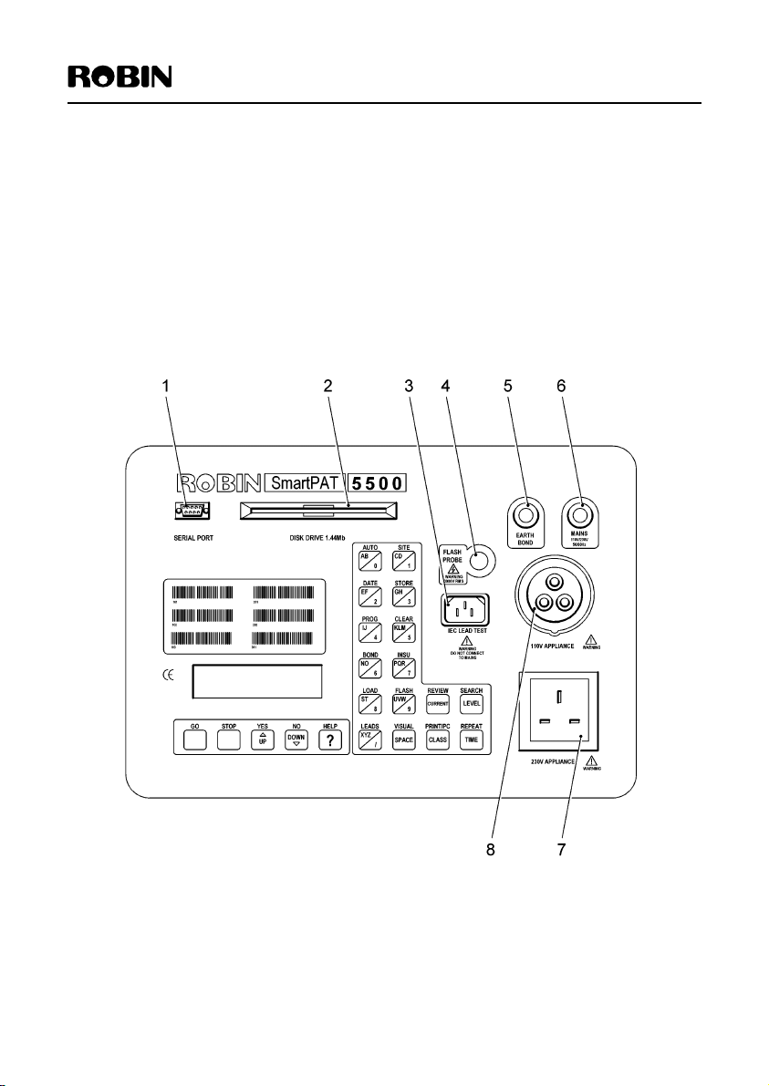
Controls and Accessories
The cables, connectors, controls and indicators of the SmartPAT 5500 are shown in Figure 2 and listed
below,together with a brief functional description:
Cables
Mains Captive mains cable to connect to the mains supply with either a
13A, 230V or a 16A, 110V plug (via adaptor). (See Figure 2 (6))
Earth Bond Captive cable, fitted with heavy duty crocodile clip,to connect to
appliance under test. (See Figure 2 (5))
Connectors
110 V Appliance Provides a socket to connect a 110 V appliance to the test set for
testing. (See Figure 2 (8))
230 V Appliance Provides a socket to connect a 230 V appliance to the test set for
testing. (See Figure 2 (7))
IEC Lead Test Enables IEC leads to be tested, used in conjunction with the 230 V
Appliance Input socket. (See Figure 2 (3))
Serial Port Allows an external computer/printer or any serial interface data
collector device to be connected to the Portable Appliance Tester.
(See Figure 2 (1))
Flash Probe Enables a probe to be inserted into the Portable Appliance Tester, to
allow high voltage insulation tests to be carried out. (See Figure 2 (4))
Disk Drive
Disk Drive 1.44Mb A 31/2” floppy disk drive to provide a means of storing the records
so that later they can be downloaded to a computer. (See Figure 2 (2))
WARNING
When transferring data to a floppy disk it is essential that the data is either
transferred to a computer or printed before the data is deleted from the tester.
6
Page 8

SmartPAT 5500
Controls
The controls are all in the form of keys, there are two distinct sections:
Main executing keys
Test function and setting keys
Main Executing Keys
GO Initiates tests and confirms selections.
STOP Terminates tests and selections, when pressed returns display to show main
menu, see setting up section.
YES Allows a positive decision to be made, the key is also the up arrow for use
when scrolling through messages or lists.
NO Allows a negative decision to be made, the key is also the down arrow for use
when scrolling through messages or lists.
HELP When pressed will display a help message on the subject the SmartPAT 5500 is
currently employed in carrying out.
Test function and setting keys
These keys perform various functions, the alpha-numeric keys, half black and half yellow, provide the
keyboard function for the PAT together with the space key.The use of these keys is detailed in the
Installation section under setting up. The other four keys provide a means of amending the test
parameters, ie alter current used or time duration of test.
All the 16 keys have a black legend above them, these are the function which that key will control.
A brief description of the action controlled by each key is as follows:
AUTO Enables any autotest programmed in the SmartPAT 5500 to be selected
and run.
SITE Allows a code for each site testing is carried out at to be entered into the PAT
memory for storing on the records.
DATE Enables the date and time to be set in the PAT, this is automatically updated by
the PAT.
STORE Allows a test result to be stored in the PAT.
PROG Initiates the programming mode of the PAT,For some of the major modes the
access code is required. (For Access Code details see Programming section)
CLEAR Enables results to be erased from the memory.
BOND When pressed this key will initiate an earth bond test.
INSU When pressed this key will initiate an insulation test.
LOAD When pressed this key will initiate a load/leakage test.
FLASH When pressed this key will initiate a flash test.
LEADS When pressed this key will initiate an IEC lead test.
VISUAL When pressed will allow the results of a visual test to be entered into
the records.
REVIEW Enables the results of an auto test to be viewed before they are stored, or any
stored result may be viewed.
SEARCH Enables a search of the records to be carried out.
REPEAT Allows a search to be repeated.
PRINT/PC Enables the data on the display to be printed or data to be downloaded to PC
or disk. It also enables a disk to be formatted.
7
Page 9
SmartPAT 5500
Indicators
Bleeper (internal) Sounds to indicate that a test has been completed or failed (double bleep).
Display Dot matrix Liquid Crystal Display, displays up to 40 characters at a time,
in two lines, to show the following:
Test type selected
Test in progress messages
Test results
Warning messages.
Help messages
Figure 2 Controls and Accessories
8
Page 10

SmartPAT 5500
Results
The test results are displayed on the display screen, showing the actual measured values, or when necessary
the reason for failure, eg Fuse Blown. The result may also be stored internally in a non-volatile memory,
this data is instantly available for review, printing or data transfers if required. The displayed or stored
results may be printed out by an external printer. The records will contain the site, date and appliance
being tested as well as the type of test performed.The results may also be recorded in other mediums, by
entering them in a Portable Appliance Test Log Book (Robin Manual IRPI ) or downloading the results
into a computer with a compatable PAT database management software such as Robin PowerPAT Plus
Data Management software. Both the IRPI log book and PowerPAT Plus software are available as optional
accessories from Robin Electronics.
INSTALLATION
Power Requirements
WARNING
LETHAL VOLTAGES. THE SmartPAT 5500 CONTAINS HAZARDOUS VOLTAGES,
CORRECT HIGH VOLTAGE HANDLING PRECAUTIONS MUST BE OBSERVED
AT ALL TIMES.
The power requirements of the SmartPAT 5500 are detailed under the Technical Specifications.
The Appliance Tester is dispatched from the factory with a mains lead carrying a 230V plug. To power the
Test Set from 110V requires the use of an adaptor. The adaptor is available from Robin as:
AD 110V 110V Adaptor.
Connections
WARNING
ELECTRIC SHOCK. TO AVOID ELECTRIC SHOCK, ENSURE THAT ALL POWER IS OFF AND ALL
DEVICES ARE UNPLUGGED BEFORE CONNECTING OR REMOVING ANY OF THE TEST CABLES.
CAUTIONS
EQUIPMENT DAMAGE. The equipment has been set for a nominal 230V/110V operation, it must never
be connected to a higher voltage.
EQUIPMENT DAMAGE. The mains supply is never to be connected to the IEC lead test connector.
The only connection to be made prior to commencing testing is to plug the SmartPAT 5500 into the
correct power source.
9
Page 11

SmartPAT 5500
Setting Up
The only requirement to set up the Test Set, is to find a suitable place to conduct the testing, adjacent to
the correct power source,(230V/110V 50Hz).
The Appliance Tester has no ON/OFF switch, it is ready for testing equipment as soon as power is
applied to it.
When the Tester is plugged in and power applied the Tester performs a short test of the mains supply voltage
and displays the version of the software within the unit.The following screens are displayed in quick succession:
Robin SmartPAT 5500 Robin SmartPAT 5500
Self Test VI.17 230V Operation
A quick self test is then performed to check the functioning of the Test Set, on completion of which the
following message is displayed:
Site ABC
19/08/1999 08:35:24
This screen is the main screen from which all operations are initiated.
NOTE
During any operation of the SmartPAT 5500, pressing the STOP button will automatically revert to the
above screen
Use of Alpha Numeric Keypad
The SmartPAT 5500 is accessed and controlled via the alpha numeric keypad. Therefore before installing
the equipment in the test position it is necessary to have a complete
understanding of how to use the keypad.
The following example shows how to enter alpha or numeric characters
KLM To enter the numeric 5 press key once, character K press key twice,
for L press key three times and for M press key four times.
If the data to be entered is numeric, ie. Date and time, then the
5 alpha function is inhibited.
DATE
When the function is required that is shown above a key, with the exception
of the five Executing keys, pressing the key will call up that function, unless the
equipment is in a mode that inhibits that function. The sixteen function keys
are shown on Figure 2 and listed on page 8.
The keys that have a word, with the exception of SPACE, enable
LEVEL
The keys and buttons are detailed in the Control and Accessories section
10
alterations in the test instructions to be inserted. The four keys are:
CURRENT Allows the different current ratings to be set in a test
5A, 8A or 26A.
LEVEL Enables the user to change the Pass/Fail Level of selected tests
CLASS Selects the class of the equipment under test, Class 1/Class11
TIME Enables the time duration of each phase of a test to be amended
Page 12

SmartPAT 5500
Setting the Date/Time
The date set will be the date recorded on all the result records. Once set the date and time is automatically incremented, but should be checked on switch on before commencing any tests. To adjust the date
and time:
Press DATE button, the following is displayed:
Enter date, press GO
19/08/1999 08:40:25
If no change is required press GO button, display will return to the main screen
The cursor will be highlighting the first character of the date. If a change is required enter the date,
followed by the time in the following format,using the keypad.
dd/mm/yy hh:mm
On completion of the operation press GO button, display will return to the main screen.
Setting the Site
This allows a site to be identified and subsequent tests to be recorded for/under the site. A recognition
code is entered, so that the place of testing (site) is registered on all result records. Failure to set the
site recognition code will result in the code entered for the last site being recorded on all the result
records. Once a site as been allocated to a record it is not possible to amend the record, only to delete it.
If no change is required remain with the main screen,no further action is necessary. To set a new site
code:
Press SITE button, the following is displayed:
Enter site, press GO
…………
The cursor will be highlighting the first character of the code. Enter required site code using buttons on
the keypad as detailed in Use of Alpha Numeric Keypad at the start of the Installation section
On completion of the operation press GO button, display will return to the main screen
The SmartPAT 5500 is now ready to commence testing the appliances.
11
Page 13

SmartPAT 5500
OPERATING INSTRUCTIONS
Prior to performing any test the following information is required.
The class of equipment to be tested, see Table 1;
Table 1
Class Typical Appliances
1 (Normal) Electric heaters, Fans, kitchen appliances, kettles etc.
1 (Business) Business machines - Fax machines, printers, personal computers etc.
II Double insulated appliances - Power tools,table lamps etc.
Business equipment usually contains electronic components and are therefore are susceptible to damage
from high current and voltage. For this reason the Earth Bond tests are carried out using the 100mA test
current
Fuse Continuity tests are valid for the more common conventional electrical equipment, but certain
appliances contain circuitry that is unlikely to give a positive reading eg; High input impedance of solid
state devices etc. Examples of the type of equipment which would indicate a failed test, even when the
equipment fuse is good are:
Personal computers
Monitors (VDU)
Fax machines
Photocopiers
Motor driven hand tools with electronic control.
WARNING
Before commencing any testing the user is strongly advised to make reference to the Electricity at Work
Regulations 1989 and any relevant publications from the Health and Safety Executive. It is important that
the user fully understands the various tests required and how they should be performed.The user should
also make reference to the Code of Practice for In Service Inspection and Testing of Electrical Equipment,
which is available from the Institute of Electrical Engineers. Robin Electronics also produce a useful video
guide to PAT testing. (Robin model RV20)
TESTING
NOTE
If during any operational actions further information on the test or action is required, pressing the HELP
control key will display a number of hints to assist in the correct operational procedure.
Visual Check
1 Check state of flex, ie. No cuts, cracks or any physical damage to the outer insulation layer.
2 Check state of the plug, cable securely attached, no signs of overheating and that the
correct value of fuse is fitted.
3 Check the equipment to be tested for any signs of damage, and that any mains or control switches will
physically switch on and off.
4 Check any sockets for signs of overheating or physical damage.
Auto testing
The list of tests pre-programmed into the SmartPAT 5500 are given in table 2 together with the limits and
time duration of each phase of the test.
The procedure to carry out an autotest is detailed after table 2, with a example of the type of display and
actions required to perform the tests.
12
Page 14

SmartPAT 5500
Table 2 Automatic Tests
Test No Tests Time Pass/Fail point
101 Visual check
26A earth bond test 10s 0.1ohm
Insulation, Class 1 10s 2.0Mohm
Load: load 10s 3kVA
leakage 1.0mA
102 Visual check
26A earth bond test 10s 0.1ohm
Insulation, Class 1 10s 2.0Mohm
Flash 10s 1.0mA
Load: load 10s 3kVA
leakage 1.0mA
103 Visual check
100mA earth bond test 10s 0.1ohm
Insulation, Class 1 10s 2.0Mohm
Load: load 10s 3kVA
leakage 1.0mA
201 Visual check
Insulation, Class II 10s 7.0Mohm
Load: load 10s 3kVA
leakage 10s 1.0mA
202 Visual check
Insulation, Class II 10s 7.0Mohm
Flash 10s 1.0mA
Load: load 10s 3kVA
leakage 10s 1.0mA
301 Visual check
8A earth bond test 0.1ohm
Insulation test 7.0Mohm
Note
The results shown in the following tests have typical values for example purposes.
To perform an auto test the procedure is as follows:
Press AUTO key, the following is displayed:
Enter the Autotest
Number, press GO
After 2 seconds the display changes:
Autotest
Autotest number: 101
13
Page 15

SmartPAT 5500
Press the key for the first number of the autotest, eg 1, the number on display will be removed and the 1
just entered will be displayed. Enter the next two numbers.
On completion press GO key
Check case exterior,
Cable and plug
After a few seconds the display changes to:
Visual inspection
YES/NO for PASS/FAIL
Check the appliance under test for any visible damage as detailed under the Visual Check heading. If no
damage found press YES key for PASS. If damage found press NO key for FAIL. The Visual inspection
screen will be redisplayed with either PASS result or FAIL result displayed.
After a few seconds the display changes to:
Earth bond 26A
Attach earth clip
After a few seconds the display changes to:
Earth bond 26A
Press GO to start
Press GO key, the following screen is displayed:
Earth bond 26A
Test in progress 10
The test is of 10 seconds duration, this is counted down by the numeric counter in the right hand corner
of display. The result of the test is then displayed:
Earth bond 26A
Resistance >0.08Ω
If the resistance is too high then the screen will show FAIL indicated by a double bleep and after a few seconds the
screen below is displayed.
Fig 1
This allows you to perform a re-test of the earth bond. Press YES key to re-test.You can
perform a re-test as many times as you wish but if the earth bond still fails or the NO key is pressed the
tester will not allow you to proceed with a subsequent test on the appliance as there is clearly a safety
fault. In this case the tester will ask you to review or store the failed fault.
Earth bond 26A
Re-test? Yes/No
If the resistance is low enough then PASS is displayed and the next screen, the Insulation test is displayed:
Insulation Class I
Remove earth clip
After a few seconds the screen changes to:
Insulation Class I
Press GO to start
14
Page 16

SmartPAT 5500
Press GO key, the following screen is displayed:
Insulation Class I
Test in progress 10
The test is of 10 seconds duration, this is counted down by the numeric counter in the display. The result
of the test is then displayed. If the test fails you will then see a message similar to
Insulation Class I
Resistance >300MΩ
After a few seconds the test changes as shown on screen:
Load/Leakage 230V
Press GO to start
Press GO key to continue the following screen is displayed:
Load/Leakage 230V
Testing Fuse
If the fuse is OK the screen will display:
Fuse Intact
Press GO to continue
If the fuse is not OK the screen will display:
Fuse Appears Blown
or Low Load Rating
And after a few seconds the screen will display:
Continue? Or Re-Test Fuse?
GO/YES/NO
Fig 1.
If the GO is pressed the unit will proceed to a Load/Leakage Test.This will flag the fuse test as a pass and
must only be done after the fuse has been checked manually. If the YES (UP) Key is pressed the unit will
re-test the fuse. If the NO key is pressed the unit will record the Load/Leakage Test as a fail result.The above
procedure allows you the option of checking or replacing the fuse if the tester identifies a problem with the
fuse.Any problem must be corrected prior to continuation of any testing if a fail result is to be avoided.
While the test is in progress for the 10 seconds, the 230V displayed is alternated with a WARNING sign.
Press GO key to continue.The unit will proceed to a Load/Leakage Test.
The user should exercise caution with the equipment as the appliance under test will power up during
the test sequence. On completion of the test the results are displayed:
Load/Leakage
VoltAmp 838VA
After a few seconds the screen changes to show the leakage current:
Load/Leakage
Leakage 0.0mA
After a few seconds the display changes to the screen below. If the test fails you will then see a
message similar to
Fig 1.
Autotest complete
Use REVIEW or STORE
15
Page 17

SmartPAT 5500
Reviewing
To review the results of the test the procedure is as follows:
Press the REVIEW key, the display shows:
Reviewing autotest
results. Use REVIEW
Press REVIEW key, display then shows a series of screens running through the test just performed. The
first screen displays the result of the first part of the test being reviewed, to view the remainder of the
test results, press REVIEW key for each screen until all the tests have been reviewed. If the stop key is
pressed during the review process the screen will revert to the main menu and the results will be lost.
Storing
To store the results of the test:
Press STORE key, the display will show:
Use the Keypad,then press
GO, or use the wand
After a few seconds the screen changes to show:
Enter the appliance num:
……..….
Enter the appliance reference number using the keypad.This number is normally a unique reference
number for the appliance under test, typically the serial number. If you are using PowerPAT Plus this is
where the optional dummy test code would be entered. If available the code may be entered using the
barcode wand, see manual for instructions in the use of the barcode wand. On completion press GO
The following screen will be displayed:
Use Keypad,then GO
or just GO to skip
The screen then changes to display the following:
Enter a note
……………………………..
If required a note on the tests may be entered into the records at this stage. (At this point users that are
using the tester in conjunction with Robin’s PowerPAT Plus Software can enter the relevant appliance
description and location code. On completion,or if no note is required press GO.
The display shows:
Results stored in
record 2
On completion press STOP to return to main menu.
Storage Type
To print a record, download a record or format a disk the procedure is as follows:
Press the PRINT/PC key the following is displayed:
Print results
YES/NO ?
16
Page 18

SmartPAT 5500
To select anything other than a print out on a printer requires the selection of NO. To print out on a
printer pressYES.The screen displays:
Fig 2
Use the up/down arrow keys to select the first record number that is to be printed, then press GO. The
screen displays:
Fig 2a
Use the up/down arrow keys to select the last result number that is to be printed, then press GO.
The selected records can then be printed out and the screen displays:
Press stop to revert to the main menu.
If NO is selected at the PRINT/PC screen the following is displayed:
SelectingYES displays the following:
After a short wait, if no disk has been inserted it will display insert a disk and press GO, the reading
disk screen is redisplayed. After a wait for the disk to be read the following screen is displayed
The unit will download from memory all the test results to a file called Robin.rob. If you wish to use
your own file name, press NO key and use the alphanumeric keys to set up your own file name. On
completion press GO, the screen displays:
After a short wait the following is displayed:
First result 1
Last result 10
Print Complete
Download to floppy
YES/NO
Please wait
Reading disk
Enter File name, Go
Robin.rob
Note: PowerPAT Plus will only recognise files named Robin.rob.
Please wait
Downloading to disk
Downloading complete
Press STOP and return to main menu.
When NO is selected at the Download to Floppy screen the following screen is displayed:
Download to Robin
PowerPAT Plus YES/NO
A screen similar to
SelectingYES displays the following:
Fig 2 and Fig 2a will be displayed.
Please wait
Downloading
17
Page 19

SmartPAT 5500
After a short wait the following is displayed:
Downloading complete
Press STOP and return to main menu.
When NO is selected at the Robin PowerPAT Plus screen the following screen is displayed:
Download to Robin PAT Test 5000
YES/NO
A screen similar to
After a short wait the following is displayed:
Press STOP and return to main menu.
If NO was selected at the PAT Test 5000 screen the following is displayed:
SelectingYES displays the following:
After a short wait the following is displayed:
Fig 1 and Fig 2 will be displayed.
Please wait
Downloading
Downloading complete
Download to PC database
YES/NO
Please wait
Downloading
Downloading complete
Selecting YES displays the following:
Press STOP and return to main menu.
If NO was selected at the download to PC database screen the following is displayed:
Downloading as industry
standard? YES/NO
Selecting YES displays the following:
Please wait
Downloading
After a short while the following is displayed:
Downloading complete
Press STOP and return to main menu.
If NO was selected at the download to Industry Standard the following is displayed:
Print Auto-Test
18
Sequences? YES/NO
Page 20

SmartPAT 5500
Selecting YES allows the printing of newly programmed Auto-Test Sequences if a printer is connected.
If NO was selected at the print Auto-Test Sequences Screen the following is displayed:
Format a disk
YES/NO
If YES is selected then the following screen is displayed:
Please wait
Formatting a disk
On completion the following is displayed:
Formatting complete
Press STOP and return to main menu.
Press NO at the Format a Disk screen and the screen returns to the opening print results screen.
Clearing or Reviewing Stored Records
The stored test records can be reviewed by pressing the review button the screen displays:
Use UP/DOWN to select
a record
The UP/DOWN key can be pressed to select a record which can then be reviewed by subsequent
pressing of the review button.
Press STOP to return to the main menu.
Stored test records can be deleted individually or all at once.To delete records press the clear button, the
screen displays:
Select record with UP/DOWN
Press GO to
and then:
Clear record. Hold GO
down to clear all
Note: Once deleted,records cannot be retrieved.
19
Page 21

SmartPAT 5500
Programming
The programme mode has a number of functions, the major functions require the entry of an access code
before the tester will allow that function to be actioned.
The access code is set at the factory to 9999.
Press the PROG key, the following screen is displayed:
Enter or change an
autotest? YES/NO
To select the programming mode required or to view the selection of modes available press NO. At each
screen as it is displayed press NO to view the next mode.
Set communications
speed ? YES/NO
Set floppy storage
format ? YES/NO
Set up Professional/
Normal mode ? YES/NO
Set up Diagnostic
test lockout ? YES/NO
Change access code ?
YES/NO
Selecting NO at the last choice reverts to programming mode opening screen
Autotest
Enter or change an
autotest? YES/NO
Press YES to perform this function.
Enter access code
….
Enter access code, then press GO, the following is displayed:
Enter a new autotest
number to edit or
the message continues on the second screen.
An existing autotest
number to copy
After a few seconds the following screen is displayed:
Autotest number: . ..
If the number entered is not of the correct format the screen will flash with the message Invalid
autotest. On completion press GO. The unit will now ask you to assign a copied autotest sequence a
new number, eg 107. On completion press GO.
20
Page 22

SmartPAT 5500
A new autotest may now be programmed or an existing test edited to suit the testing requirements, it will
be assigned the new autotest number, eg 107. Use the up/down arrow keys to run through the various
test parameters. The screen will display steps to be taken to select or skip parameters to be included or
omitted from the new autotest number.
The values within each parameter test sequence, for example if you wish to include an Earth Bond Test
you can change the value of that current, the pass level and the test time duration by using the
CURRENT, LEVEL,CLASS and TIME keys
On completion the screen displays:
Use Review/Store to
Review/Save Autotest
Pressing the REVIEW key will allow you to scroll through the test sequence you have selected. If all the
details are correct press STORE, the screen will display:
Autotest Stored
In Number....………….107
This new autotest can now be selected in future tests using autotest code 107.
Communication Speed
Set communications
speed ? YES/NO
Press YES to perform this function.
Use UP/DOWN then GO
Speed: 9600bps
Use the UP/DOWN controls to select the speed required for the interface. The range is:
1200bps
2400bps
4800bps
9600bps
On completion press GO, the following is displayed to confirm the speed has been set:
Speed: 4800bps
Press STOP to return to main menu
21
Page 23

SmartPAT 5500
Storage format
Set floppy storage
format ? YES/NO
Press YES to perform this function.
Use UP/DOWN then GO
Format: Print
Use the UP/DOWN controls to select the storage format required. The selection is:
Print Robin.txt = Text document
PC database Robin.csv = Comma separated variable file
PowerPAT Plus Robin.rob = PowerPAT Plus document
Industry Std Robin.ind = Industrial file
Note: If you are using Robin PowerPAT Plus software or Robin PATEST 5000 software select
“PowerPAT Plus”
On completion press GO, the following is displayed to confirm the selection as been set:
Format: Print
Press STOP to return to main menu
Professional/Normal
The Tester can be selected for operation in the Professional or Normal mode.
In the Professional mode the messages displayed to the user during the test sessions are reduced along
with the test duration times. This allows a user who is familiar with the test sequences and the actions
the test performs to reduce the testing time and increase the speed of work.
In the Normal mode all messages are displayed and the tester guides the user through each individual
action. It is recommended that Normal mode is selected until the user is fully practised in using the
tester and understands the functions of each test,
Professional Mode is only for experienced and competent users.
Set up Professional/
Normal mode ? YES/NO
Press YES to perform this function.
Enter access code
….
Enter access code, then press GO, the following is displayed:
Code accepted
After a few seconds the following screen is displayed:
YES for Professional
or NO for Normal
22
Page 24

SmartPAT 5500
Press the required control to select the required mode
The display will show which mode is selected:
Professional mode
selected
Press STOP to return to main menu.
Diagnostic test Lockout
This function allows the user to ‘LOCKOUT’ or prevent the selection of manual tests. Only the autotests
are available when this function is selected. This is essentially a safety feature and prevents inadvertent
selection of a manual test when performing auto sequence testing by accidental operation of the keypad.
Set up Diagnostic
test lockout ? YES/NO
Press YES to perform this function.
Enter access code
….
Enter access code, then press GO, the following is displayed:
Code accepted
After a few seconds the following screen is displayed:
YES lock out, NO
to allow Diagnostics
Press the required control to select the required mode
The display will show the selected mode, locked out or enabled:
Diagnostic tests are
locked out
Press STOP to return to main menu.
Change Access Code
Change access code ?
YES/NO
Press YES to perform this function.
Enter access code
....
Enter access code, then press GO, the following is displayed:
Now enter new code
....
On completion press GO. the following is displayed
Re-enter new code
....
23
Page 25

SmartPAT 5500
Re-enter new access code, then press GO, the following is displayed:
Code accepted
Press STOP to return to main menu
IEC Lead Test
Plug the lead to be tested between the IEC LEAD TEST socket and the 230V APPLIANCE socket on the
SmartPAT 5500.
Press the LEADS key, the following screen will be displayed:
Lead test: Bond 5A
Press GO to start
The current may be set to the required level by using the CURRENT key. The range allowed is:
5A
8A
26A
When ready to test lead press GO, the SmartPAT 5500 will then cycle through an Earth Bond test, an
Insulation Resistance test and a Polarity/Fuse test, the results are displayed sequentially until the STOP
control is pressed. If the results are required to be stored then the STORE key must be pressed before
the STOP. When the STORE key is pressed the results can be stored in accordance with the procedure
detailed in this manual under the heading ‘Storing’.
Manual Testing
Individual Manual tests may be carried out at any time on an appliance by pressing the appropriate key
and following the on screen instructions. The tests are as follows:
Earth Bond BOND
Insulation INSU
Load/Leakage LOAD
Flash FLASH
Visual Inspection VISUAL
The results can be stored, reviewed, printed or downloaded as required. To stop any manual test the only
action required is to press STOP.
When performing a manual Earth Bond test, the test current can be selected as 100mA, 5A, 8A or 26A
using the CURRENT key.
When performing a manual Insulation Resistance test, the Class of the equipment under test can be
selected for Class I or Class II using the CLASS key.
When performing a manual Flash test, a flash voltage of 1500 V for Class I appliances or a flash voltage of
3000 V for Class II appliances can be selected using the CLASS key
24
Page 26

SmartPAT 5500
FAULT FINDING AND REPAIR
Should any faults develop on the SmartPAT 5500,the equipment is to be returned to ROBIN. There are
no user facilities to repair the test set, due to the technical nature of the equipment. In the event of a
fault developing return the equipment to the Service Department at the following address:
ROBIN
52 Hurricane Way,
Norwich,
NR6 6JB
Calibration
To ensure the accuracy of the equipment is maintained at a high level, it is recommended that the Portable
Appliance Tester be returned to the above address for calibration at least once every 12 months. If the
results at any time give rise to doubt the equipment should be returned straight away for safety reasons.
Always state clearly what the reason for return is
Basic Maintenance
The SmartPAT 5500 test set has a fused moulded mains plug fitted. The only user maintenance on this is
the changing of the fuse. However if the plug is damaged then the moulded plug must be cut off and a
new 3 pin fused plug fitted by a qualified electrician
GENERAL ENQUIRES
Robin Electronics operate a technical helpline to assist customers in the use of Robin products. A
selection of the most common enquires received regarding portable appliance testing together with the
answers are given below:
My PN fuse test fails?
The objective of this test is to check to see if the appliance fuse is fitted. An appliance will fail the fuse
test if the fuse is not fitted or has failed. Some appliances are electronically controlled,i.e. they may have
semi-conductor devices in the supply path. This will give a high input resistance to the appliance and may
cause the equipment to fail the test. When a fail is shown on the tester pressing GO will assign a pass to
the fuse test.This must only be done after the fuse is checked manually.
How do I program an auto test ?
Refer to the Programming mode section of this manual. Simply step through the test sequence as detailed
and define your own specific auto test as required. The factory setting for the access code is 9999.
How do I skip a test ?
To skip a specific test, you can either test manually or programme a new test in the auto mode. If you
want to programme a new test refer to the Programming mode section of this manual. Go into auto
mode, set a new test sequence and define a new test code for the specific sequence. Omit any particular
test you do not wish to be included in the auto sequence as detailed in the manual.
25
Page 27

SmartPAT 5500
How do I test my extension lead for the Earth, Insulation and Load tests?
Earth tests and Insulation tests on extension leads can easily be undertaken using a special ROBIN
Extension lead test adaptor (catalogue code EL 100). A load test is not applicable to an extension lead
and is therefore not required.
What tests should I do?
For a comprehensive overview of portable appliance testing and specific tests that should be performed, it
is suggested that reference is made to the Code of Practice for In-Service Inspection and Testing of
Electrical Equipment. This document has been prepared by the Institution of Electrical Engineers and is
available direct from them. The IEE can be contacted on 01438 313311.
What is meant by class I, II and III?
There are a number of basic equipment constructions that are referred to in all standards for electrical
equipment. They are important because they determine how the user is protected against electric shock
and what tests are appropriate when assessing safety.
Class I equipment is where protection against electric shock is achieved by using basic insulation and
providing a means of connecting to the protective earthing conductor in the fixed installation wiring any
conductive parts (eg. metal) that could otherwise assume hazardous voltages if the basic insulation failed.
Consequently Class I equipment relies for its safety upon a satisfactory earth in the fixed wiring installation
and an adequate connection usually via a flexible cable to it.
Class II equipment is where the protection against electric shock is provided by a basic insulation and a
secondary level of insulation, such as a double insulation or reinforced insulation. There is no provision
for protective earthing or reliance upon installation earthing. Class II equipment should be identified with
the Class II construction mark, which is essentially a square within a square.
Class III equipment relies for protection against electric shock from an SELV source (separated extra low
voltage). The Class III construction mark should be found on such appliances and is Roman numeral III
inside a rhombus. SELV voltages will not exceed 50V. Class III equipment must be supplied from a safety
isolating transformer to BS3535.
How do I find the class of an appliance?
It is sometimes difficult to actually define the class of a piece of equipment. It is suggested that reference
be made to the appliance rating plate or look for specific construction marks for Class II and Class III
appliance which may be found adjacent to the manufacturers details on the appliance.
How do I change the pass/fail threshold?
The pass/fail threshold of any particular test should only be adjusted by persons competent in performing
the various tests with full understanding of the interpretation of the test thresholds. If you wish to
change the pass/fail threshold, refer to the Programming mode section of this manual and follow the
instructions detailed.
What are the pre-programmed pass/fail threshold?
Pre-programmed pass/fail thresholds are listed in the manual where applicable. A list of all thresholds can
be obtained from the ROBIN sales office.
Can the SmartPAT download to other software packages?
Yes, the SmartPat can download to other packages. It can download to any derivative software produced
by Shire Safety Systems. It is also compatible with the Metrotest Downloader 4 Plus System. For further
information on compatibility with other manufactures software, please contact ROBIN Electronics.
26
Page 28

Can my SmartPAT test business equipment?
For the specific test requirements on typical office equipment reference should be made to the code of
practice as defined earlier in these enquires. Two basic tests are required, insulation and earthing, however,
earthing tests must be done at low current.
My 110V drill does not power up on load test?
When using the SmartPAT all tests on 110V and 240V appliances can be done at 240V with the exception
of the load test. When conducting load tests, the power up voltage on the SmartPAT must be the same as
the rating of the appliance. For example, if you are using a 110V drill and you want to conduct a load
test, the SmartPAT must be connected to a 110V power supply.
How do I test three phase equipment?
Three phase equipment can only be tested one phase at a time. It is not possible to test all three phases
simultaneously.
Does SmartPAT read any barcode labels ?
The ROBIN SnartPAT 5500 will read any barcode up to 10 digits. The only criteria is that the barcode
must be written in code 39 format, (this is a barcode standard format).
How do I clear stored records?
Refer to Results section of this manual and step through the menu until you arrive at Clear Stored
Records. Follow detailed instructions to clear records.
How often should I calibrate my PAT tester?
Under normal operating conditions it is recommended that your PAT tester is calibrated annually. Your
PAT tester should be returned to ROBIN for all calibration requirements as ROBIN have purpose built
facilities and the equipment necessary to undertake the correct calibration procedures.
What rules/regulations does the law require?
Legislation that has specific relevance to electrical portable appliance testing and maintenance is the
Health & Safety at Work Act, the Management of Health & Safety at Work Regulations,the Electricity at
Work Regulations, and the Provision and Use of Work Equipment Regulations.
My PAT tester display has gone blank?
If this occurs you should check the incoming electricity supply to the PAT tester, check the fuse has not
blown, if these are both correct, then there may be a problem with the PAT unit and it should be
returned immediately to ROBIN Electronics for investigation.
Why do I need to do a Flash test?
You do not always have to undertake a flash test when testing portable equipment. However, a flash test
is recommended particularly when major repairs have been undertaken on the appliance under test and it
may have been stripped down to its component parts and reassembled. In this case a flash test is a useful
test to perform to ensure that the integrity of the insulation following the reconstruction of the appliance
is at least as good as when originally manufactured. Care should be taken when performing flash tests, as
to perform them incorrectly, may result in damage to the appliance under test.
Robin Electronics reserve the right to change specifications without notice and obligations
27
 Loading...