

Page 1
.
Generator
Model
RGX3510/RGX5510
RGXl810/RGX2410
Page 2
CONTENTS
Section
1.
SPECIFICATIONS ."."""• """ O"O"O"O"C."."• ""."."• "O""""O"00-0-0"""" O"O"""O"O"""""""""""""""" 1
PERFORMANCE CURVES ..". "... .... ......... .. ... .. .. .. .. . .. .. .. . .. ... .. .. .. . .. .. .. ... 3
2.
FEATURES .. .. .. ..... .. ..... .. ..... .. ... .. .. .. .. .. . .. .. ....... ..... .. ... .. .. ..... ..... .. ... 13
3.
4.
GENERAL DESCRIPTION . ..... .. ..... .. ..... .. ..... ........""" .... .. ... .. .. ... .. .. .... 14
4-1 External View
4-2 Control Panel
4-3 Location of Serial Number and Specification Number ...... ..... .. ..... .. ..... ..... 23
Construction AND FUNCTION ... ..... .. .. .. . .. .. .. .. . .. .. .. . .. .. .. . .. . .. .. .. .. ... 24
5.
5-1 Construction
5-2 Function
5-3 Generator Operation
5-4 Electronic Ignition System . ... .. .. .. . .... .. .. ..... .. ..... .. ..... ....... ..... .. ..... .. . 32
5-5 Oil Sensor ...... .. .. . .. .. .... .. ..... ..... .. ..... .. ..... .. .. .. .. . .. . .. .. ... .. .. .. .. . .. . . 32
SAFETY PRECAUTIONS ... ..... .. ..... .. .. .. .. ..... .. ..... .. ....." . .. .. .. . .. .. .. .. . .. . . 36
6.
RANGE OF APPLICATIONS .. ... .. .. .. . .. .. .. .. ..... ....... ..... .. ..... .. ..... ..... .. .. 37
7.
MEASURING PROCEDURES . ....... ..... .. ..... .. .. .. .. ... .. . .. .. . ..." . ... .. .. ..... .. 40
8.
Measuring Instruments .C...... .. .. .. . .. .. .. .. ..... ....... ..... .. ..... .. ... .. ....... .. 40
8-1
8-2 AC Output Measuring
8-3 DC Output Measuring ... ..." .. .. .. . .... .. ..... .. ....." .. ... .. .. ....".. ".. .. ... .. .. .. . 43
8-4 Measuring Insulation Resistance
CHECKING FUNCTIONAL MEMBERS . ....... ..... .. ..... .. ..... .. ... .. ..... .. ..... . 46
9.
9-1 Volt Meter ... . .. .. ..." .. .. .. .. . .. .. .. .. ..... .. ..... .. ..... ...." ... .. ..... .. ... .. .. . .. .. . 46
9-2 AC Receptacles
9-3 No-Fuse Breaker
9-4 Stator .. .. ..... ..... .. ..... .. .. .. .." . .. ..... .. ... .. .. .. .." . .. ..... .. ..... ..... .. ..... .. . 47
9-5 Rotor Assembly
9-6 Condenser .... ..... .. ..... .. ..... .. ..... .. ... .. .. .. .. ....... ..... .. ... .. .. . .. .. ..... .. 48
9-7 Diode Rectifier
9-8 Oil Sensor (Option)
Disassembly AND AssEMBLY ..................... .................................5l
10.
Preparation and Precautions
1o-1
10-2
Disassembly Procedures ... .. .. ..... .. ..... .. ..... ..... .. .. ... .. .. ... ....... ..... .. ...52
10-3
Assembly Procedures
10-4
Checking, Disassembly and Reassembly of the Control Box .. ... .. .. ..... ...”.... 65
Title
...... .. .. .. .. ... .. .. . .... ..... .. ..... .. ......."."."..............."..".. 14
...... .. ... .. .. .. . .. .. .. .. ..... .. ..... .. ..... .. ..... ..... .. ..... .. ..... ..
...... ..... .. .. .. .. .. . .. .. ..... .. ..... .. ..... ....... ..... .. ..... .. ..... .. .
...... ..... .. ..... .. .. .. .. . .... .. ..... .. ..... ....... ..... .. ..... .. ..... ..... .. . 24
...... .. .... . .. .. .. .. ..... ..... .. ..... .. ..... ....... ..... .. ..... .
...... ..... .. ..... .. .. .. .. . .. .. .. ... .. .. ..... ..... .. . .. .. .. .....
.... .. ..... .. ..... .. ..... ....... ..... .. ..... .. ..... .
...... ..... .. .. .. .. .. ..... ..... .. .. ... .. .. ... .. ..... .. .. . .. ..... .. .. .. 46
..... . .. .. .. .. ..... .. ..... ..... .. ..... .. .. .. . .. .. .. . .. ... .. ..... .. .. . 47
...... ..... .. ..... .. ..... ....... .. .. .. .. ... .. ..... . .... .. .. . .. .. .. . ....
...... .. .. . .. .. .. .. .. . .. .. ... .. .. ..... .. ..... ....... ..... .. ..... .. ..... .
." . .. ..... .. ..... .. ..... ..." . . .. .. ....... ..... .. ... .. .. ..... ....... 50
...... ..... .. .... . .. .. .. . .... .. .. ..... .. . .. .. . .. .. .. .... 51
...... .." . .. .. .. ..... .. ... .. .. ..... ..... .. ..... .. ..... ....... ... 59
Page
15
24
28
43
44
48
49
Page 3
Section Title Page
11
.
TROUBLESHOOTlNG
....................................................................
11-1 No AC Output
........................................................................
11-2 ACvoltage istoo high ortoo
low
...................................................
66
66
68
11
-3
AC voltage is normal at no.load. but the load cannot be applied
.................
69
69
71
74
11-4
No
DC Output
........................................................................
11-5 Idle Control (Option for60
Hz
only)
................................................
12
.
WIRING DIAGRAM
........................................................................
Page 4
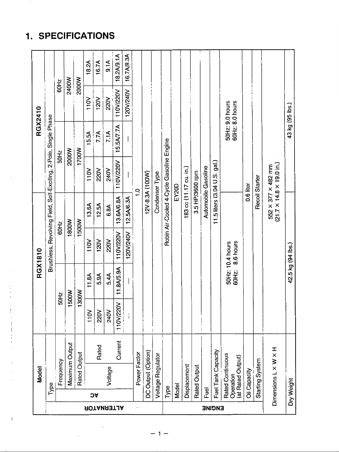
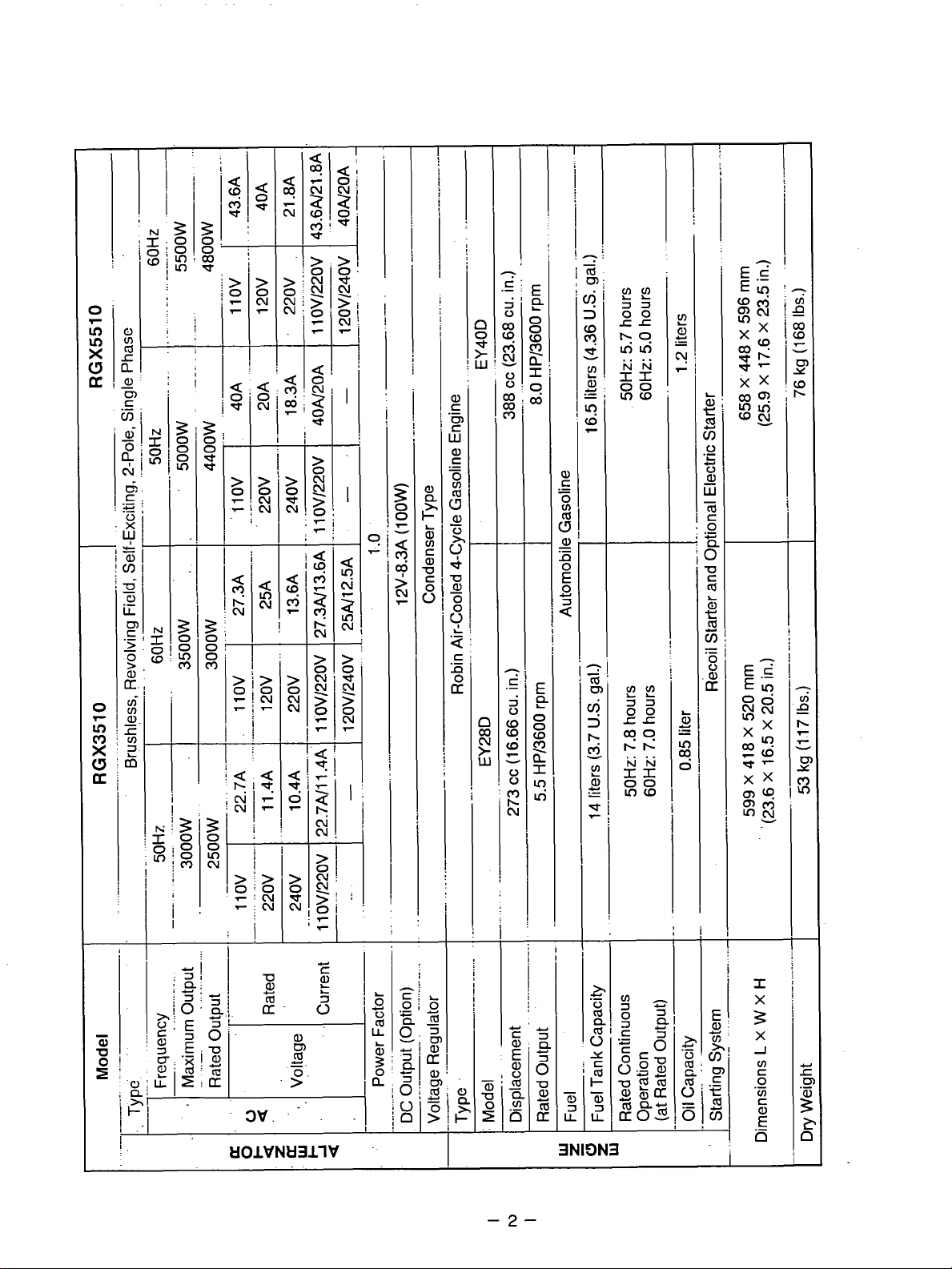
1.
SPECIFICATIONS
T
I
T
i
i
I
E
Q
I-
0
O
W
Q
a
I
Ln
m
00
rr
NN
55
Inm
01
07
m
CI
-
P
tlOlVNtl3llV
-1-
CI
3
CI
a
3NIDN3
Page 5
!
>j
c
6'
N
g
ln
-
N
g
W
i
3
0
0
0
In
-
3
0
0
m
m
si
0
d
I
?
l"
i
'_
a,
c,
m
Y
-.
8-
klOlVNkl3llV
..
i
i-
I
-2-
+
x
u
.-
0
cd
Q
s
w
ULLL
3NIE)N3
,.
iI
I
X
3
X
J
i
I
Page 6
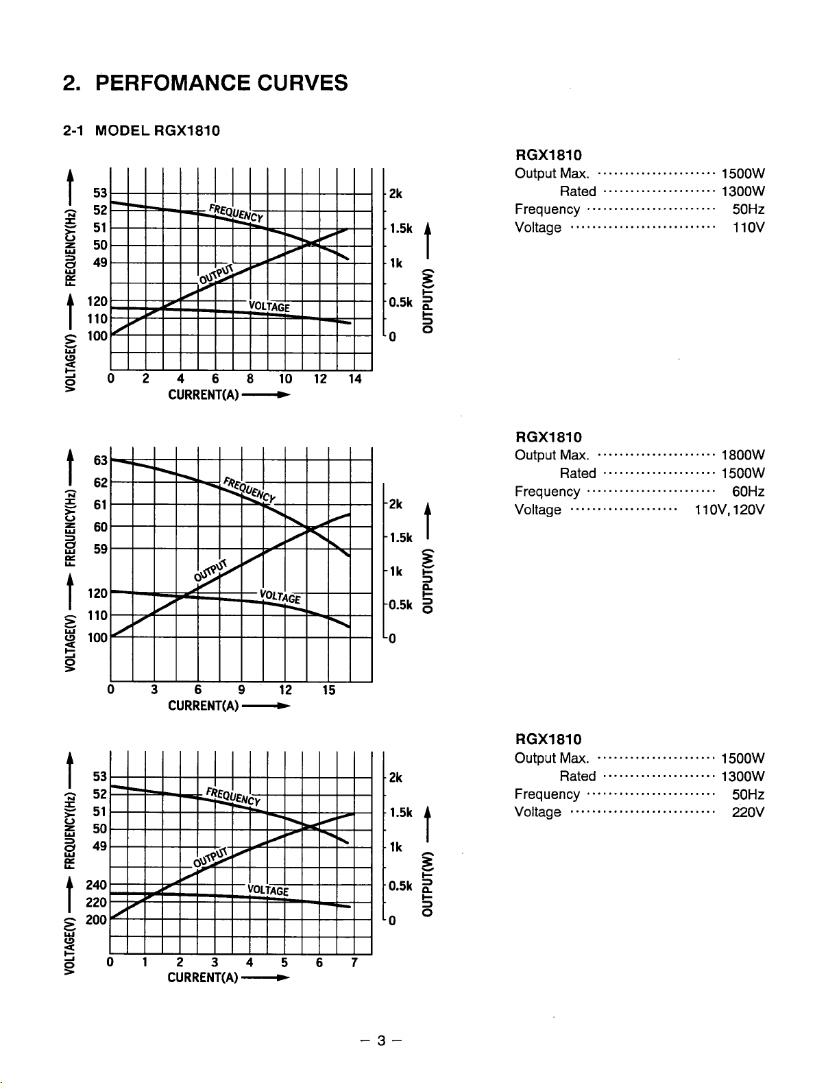
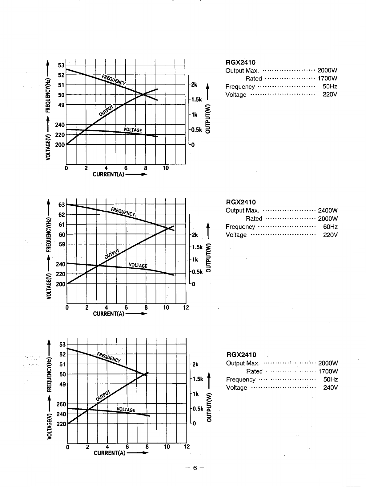
2.
PERFOMANCE CURVES
2-1
MODEL
RGX1810
2k
1.5k
lk
0.5k
0
t
z
W
I-
2
s
0
RGXl810
Output
Frequency
Voltage
Ma.
Rated
...........................
......................
.....................
........................
1500W
1300W
50Hz
110v
5
CURRENT(A)
CURRENT(A)
-
-
2k
1.5k
lk
D.5k
2k
t
F
5
n
+
RGXl810
Output Max.
Frequency 60Hz
Voltage
RGX1810
Output
Frequency
Voltage 220v
......................
Rated
.....................
1800W
1500W
........................
....................
Ma.
......................
Rated 1300W
.....................
........................
ov,
1 1
120v
1500W
50Hz
...........................
5
CURRENT(A)
-
-3-
Page 7
t
t
-1k
-0.5k
h
3
5
n
I-
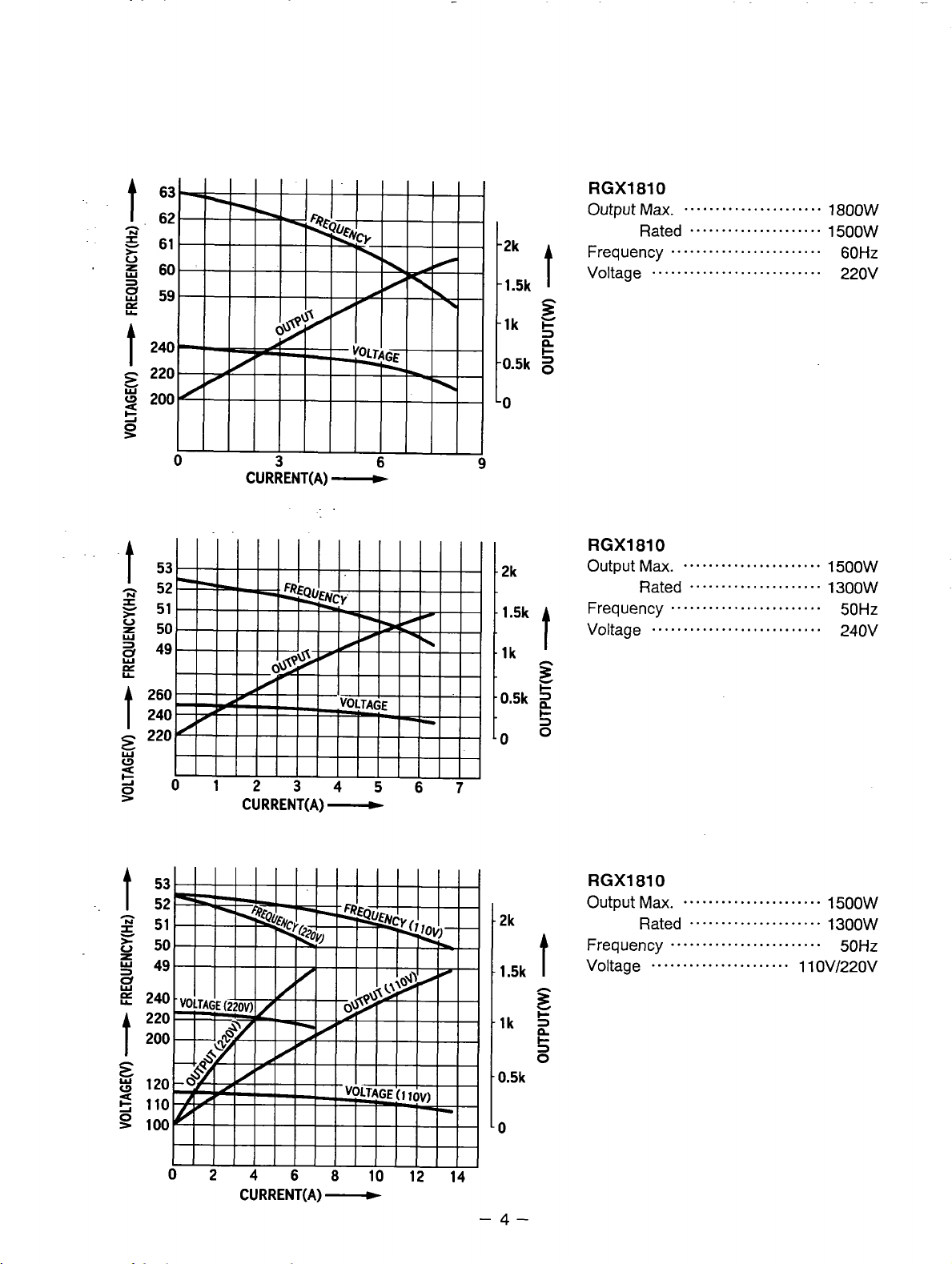
RGXl810
Output
Frequency
Voltage
Ma.
Rated
...........................
......................
.....................
........................
1800W
1500W
60Hz
220v
5
t
CURRENT(A)
CURRENT(A)
-
-
-
RGXl810
Output
12*
1.5k
lk
n
3
Y
+
-0.5k
2
t-
3
-0
o
.2k
.1.5k
t
Frequency
Voltage
t
RGXl810
Output Max.
Frequency
Voltage
Ma.
......................
Rated
Rated
.....................
........................
...........................
......................
.....................
........................
......................
1500W
1300W
50Hz
240V
1500W
1300W
50Hz
1 1 OV/220V
t
CURRENT(A)
0.5k
to
-
-4-
Page 8
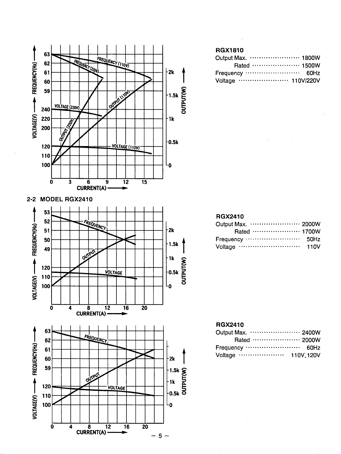
2-2
MODEL
CURRENT(A1-
RGX2410
t2k
t
‘3
-1.5k
5
5
0
-1k
-0.5k
-0
RGX1810
Output
Frequency
Voltage
Max.
Rated
......................
......................
.....................
........................
1800W
1500W
1
1
OV/220V
60Hz
h
z
>
V
3
3
s
L
t
E
Y
s
e
61
60
59
120
110
100
0
CURRENT(A)
4
8
CURRENT(A1-
C
12 16 20
/)*
1.5k
1.5k
0.5k
LO
-5-
1
0
Page 9
0
0
CURRENT(A)
2
4
CURRENT(A)
-
6
-
8
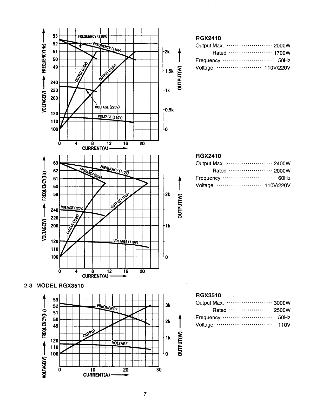
RGX2410
Output
Frequency
-2k
z
-1.5k
-0
10 12
Voltage
Ma.
......................
Rated
.....................
........................
...........................
2400W
2000w
60Hz
220v
-6-
Page 10
t
-
z
Y
*
0
5
x
s
E
240
E
220
g
200
s
=
120
110
100
53
52
51
50
49
RGX2410
Output
rk
t
1.5k
E
I-
3
n
c
3
lk
Frequency
Max.
......................
Rated 1700W
.....................
........................
2000w
50Hz
2-3
MODEL
0
RGX3510
4
8
CURRENT(A1
CURRENT(A1-
12 16 20
-
lk
0
B
CURRENT(A1-
-7-
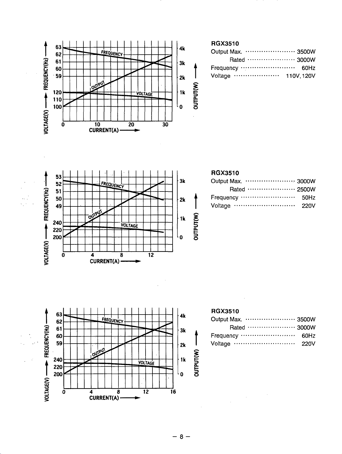
RGX3510
3k
2k
t
Output
Frequency 50Hz
Voltage
s
lk
5
00
Max.
......................
Rated
.....................
........................
...........................
3000W
2500W
110v
Page 11
4k
3k
2k
t
RGX3510
Output
Frequency
Voltage
z
lk
5
n
c
os
Ma.
......................
Rated
.....................
.........................
....................
1
1
3500W
3000W
60Hz
ov,
120v
B
CURRENT(A)
-
3k
2k
t
lk
c
3
n
5
00
t
t
63
62
61
60
59
240
220
200
4k
0
4
CURRENT(A)
8
-
12 16
-a-
RGX3510
Output
Ma.
......................
3500W
Page 12
'3k
2k
lk
0
3k
2k
lk
t
z
5
n
g
0
t
3
E
0
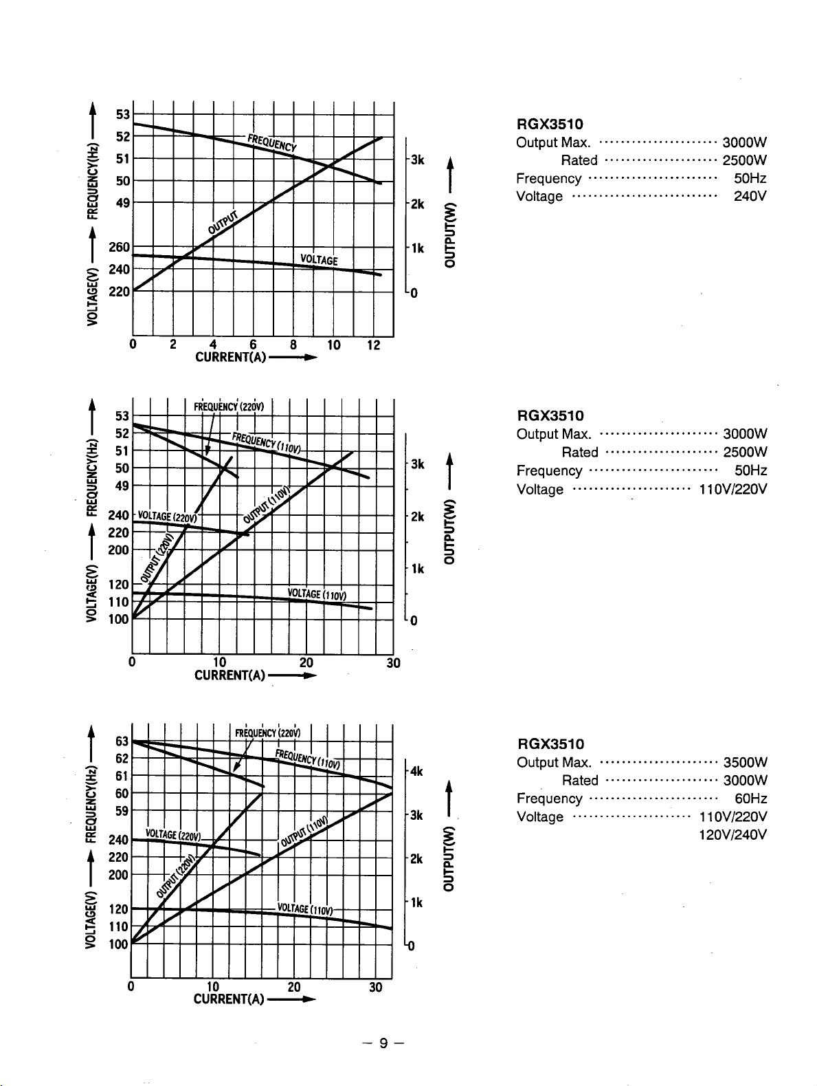
RGX3510
Output Max.
Rated
Frequency
Voltage
...........................
......................
.....................
........................
3000W
2500W
50Hz
240V
0
10
CURRENT(A)
-
20
30
0
4k
3k
2k
lk
D
t.
z
+
2
s
0
RGX3510
Output Ma.
Rated
Frequency
Voltage
......................
......................
.....................
........................
3500W
3000W
60Hz
1 1
OV/220V
120V/240V
-9
Page 13
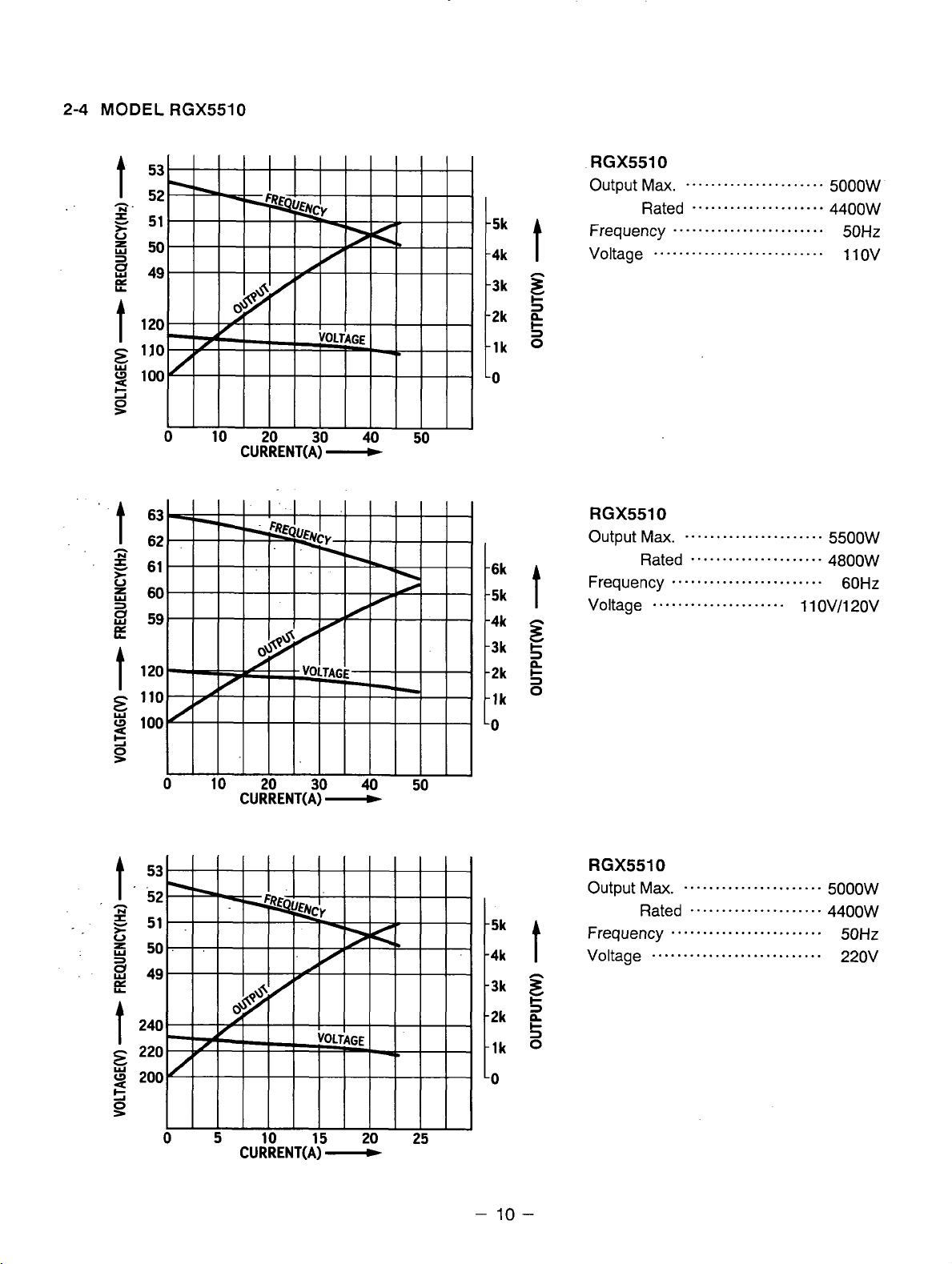
2-4
MODEL RGX5510
-5k
-4k
-3k
-2k
-1k
-0
.6k
.5k
,4k
3k
,2k
.lk
0
t
z
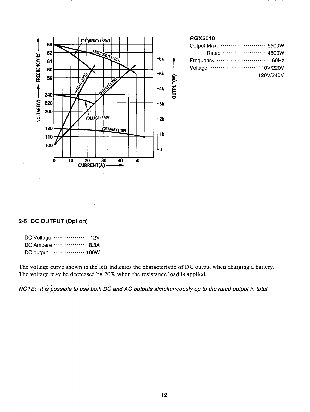
RGX5510
Output
Frequency
Voltage
Max.
Rated 4aoow
.....................
......................
.....................
........................
5500W
60Hz
1 1 OV/120V
t
CURRENT(A)
-
-
-4k
-5k
10
t
-
RGX5510
Output
Frequency
Voltage 220v
Ma.
......................
Rated
.....................
........................
...........................
5000W
4400W
50Hz
Page 14
6k
5k
4k
3k
2k
lk
0
t
z
0
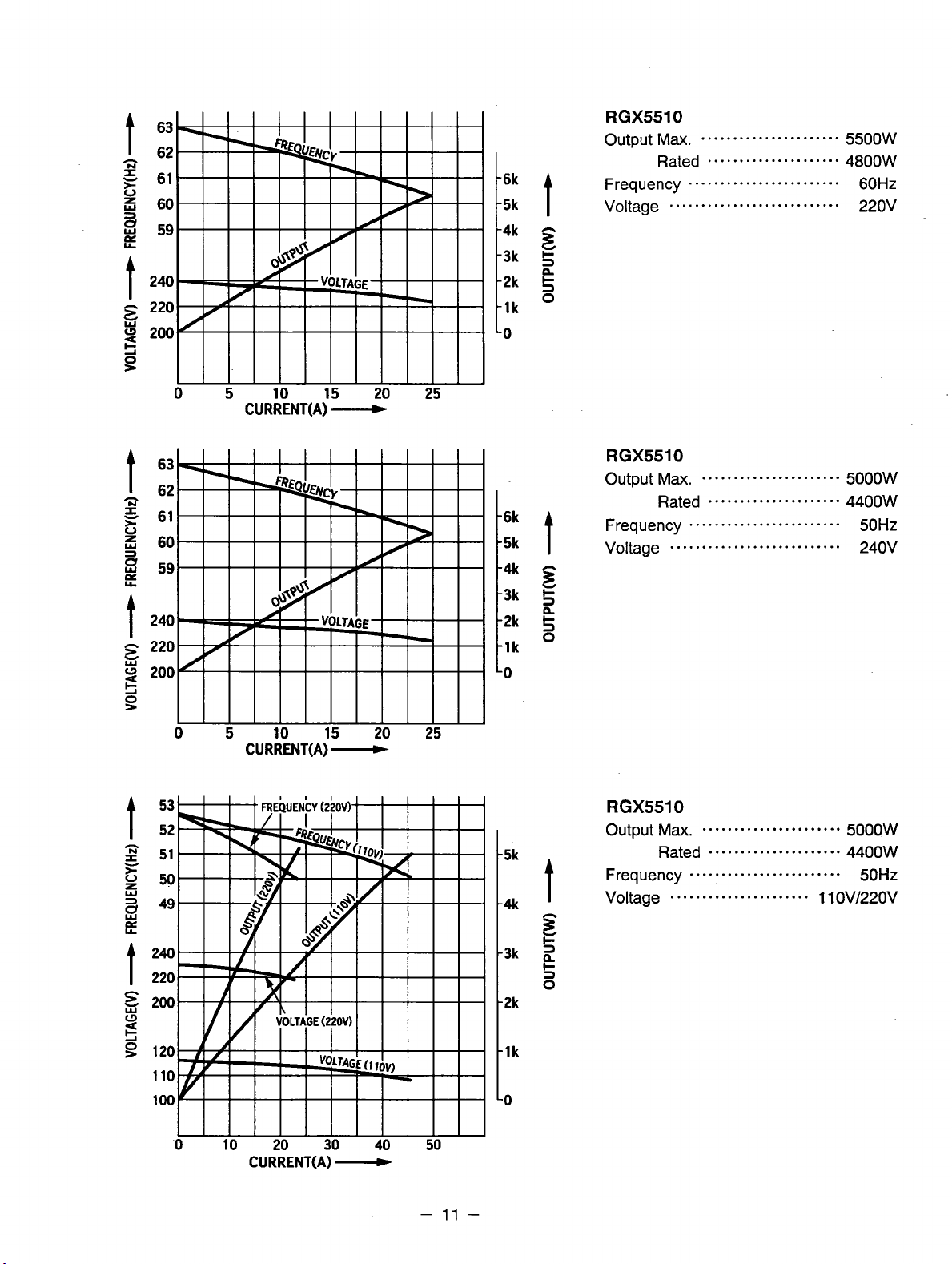
RGX5510
Output Ma.
Rated
Frequency
Voltage
........................
...........................
......................
.....................
5500W
4800W
60Hz
220v
CURRENT(A)
-
-2k
-1k
-2k
-1k
5
0
CURRENT(A)
-
-0
-
11
-
Page 15
CURRENT(A1-
RGX5510
Output
Frequency
1””t
5k
s
I-
3
-4k
g
3
0
t
3k
-2k
-1k
-0
Voltage
Ma.
......................
Rated
.....................
........................
......................
5500W
4800W
60Hz
1 1
OV/220V
12OV/24OV
2-5
DC
OUTPUT
DC Voltage
DCAmpere
DC output
The voltage curve shown in the left indicates the characteristic of
The voltage
NOTE: It is possible
(Option)
...............
...............
...............
ma,
be
decreased by
-.
to use both.DC and
12v
8.3A
1
oow
20%
when the resistance load is applied.
AC
outputs simultaneously up to the rated output in total.
DC
output when charging a battery.
-
12
-
Page 16
3.
FEATURES
3-1
BRUSHLESS ALTERNATOR
Newly developed brushless alternator eliminates troublesome brush maintenance.
3-2
CONDENSER-TYPE VOLTAGE REGULATOR
A
trouble free condenser type voltage regulator ensures a stable voltage under all working
conditions.
3-3
OIL
SENSOR
Oil sensor automatically shuts off the engine whenever the oil level falls down below the lower limit
to protect the engine from seizure.
3-4
QUIET OPERATION
Robin RGX series generator delivers a quiet operation with
0-
A
large super silent muffler.
0
A
quiet 4-stroke Robin engine.
0
A silent cyclone air cleaner.
3-5
NO RADIO NOISE
:
Soise suppressor spark plug and spark plug cap are equipped standard to prevent radio frequency
interference.
3-6
LARGE FUEL TANK
The large fuel tank allows more than 5 to
10
hours of continuous operation which is sufficient for a
half day or one day work without refueling.
3-7
RUGGED TUBULAR FRAME
Full cradle type rugged tubuler frame protects the generator all around.
3-8
COMPACT AND LIGHT WEIGHT
Newly developed brushless alternator enabled the RGX generators to be very compact in size and
light in weight.
3-9
MINIMAL MAINTENANCE
0
A brushless alternator release the operator from periodical brush maintenance.
0
A trouble free condenser type voltage regulator.
0
A drip-proof alternator design.
0
No-fuse circuit breakers.
0
An electronic pointless ignition system.
0
A
dust-proof cyclone air cleaner.
3-10
LONG-LIFE DURABILITY
The heav-duty 4 stroke Robin engine and virtually maintenance-free brushless alternator ensure
u
greater durability with
-0
A brushless alternator with a condenser voltage regulator.
0
Full rubber mount in a sturdy tubular frame.
0
A forged steel crankshaft supported by two main ball bearings.
0
A pointless electronic ignition system.
0
A
cast iron cylinder liner.
0
A forged aluminum connecting rod.
:
-
13
-
Page 17
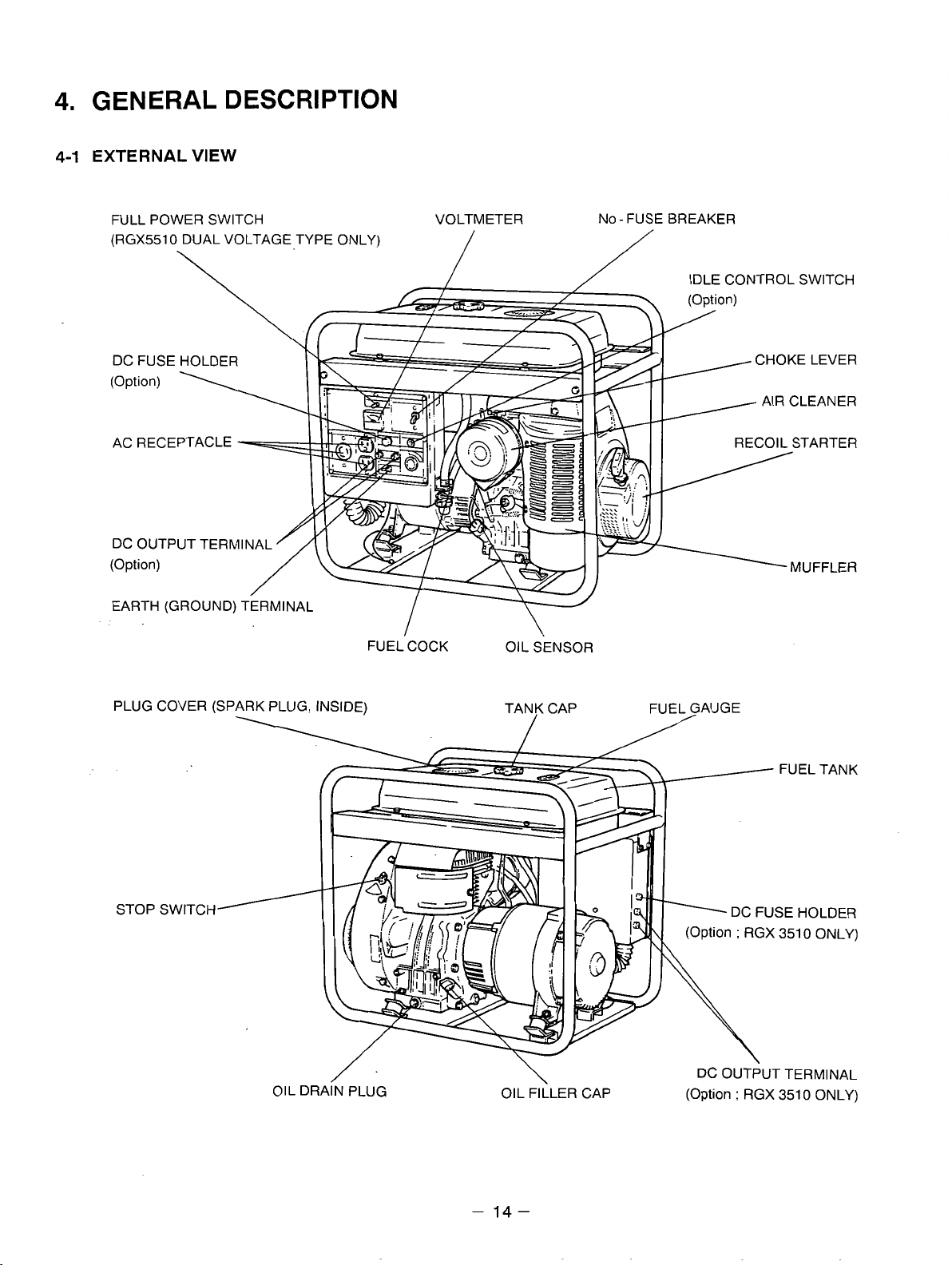
4.
GENERAL DESCRIPTION
4-1
EXTERNAL
FULL POWER SWITCH VOLTMETER NO-FUSEBREAKER
(RGX5510 DUAL VOLTAGE TYPE ONLY)
VIEW
\
DC FUSE HOLDER CHOKE LEVER
(Option)
AC RECEPTACLE
DC OUTPUT TERMINAL
(Option)
EARTH (GROUND) TERMINAL
FUEL COCK
PLUG COVER (SPARK PLUG. INSIDE)
OIL SENSOR
TAN? CAP FUEL,GAUGE
IDLE CONTROL SWITCH
AIR CLEANER
/
OIL DRAIN PLUG
/
\-
\
OIL FILLER CAP (Option
-
14-
(Option
:
RGX 351 0 ONLY)
DC OUTPUT TERMINAL
\
;
RGX 351 0 ONLY)
Page 18
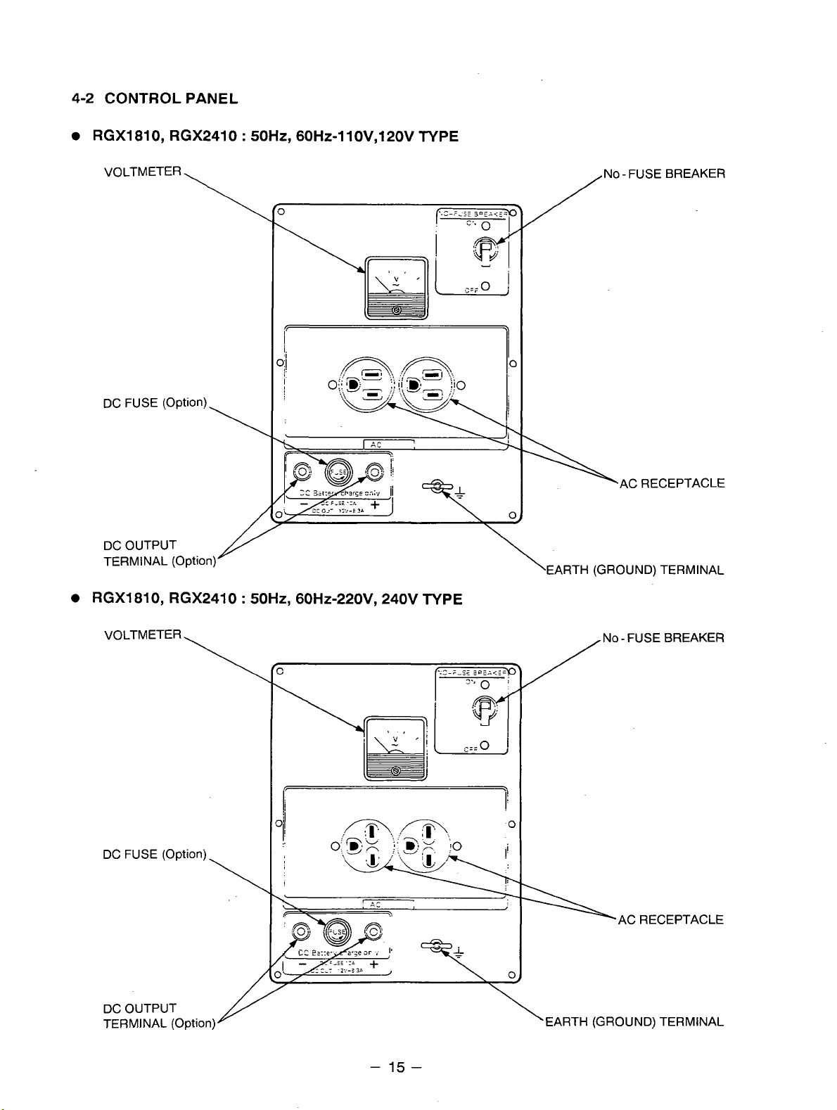
4-2 CONTROL PANEL
RGX1810, RGX2410 : 50Hz, 60H~-llOV,12OV TYPE
VOLTMETER
\
DC FUSE (Option)
\
DC OUTPUT
TERMINAL (Option)
/
\
'EARTH
No-FUSEBREAKER
AC RECEPTACLE
(GROUND)
TERMINAL
RGX1810, RGX2410 : 50Hz, 60H~-220V, 240V TYPE
VOLTMETER
DC FUSE (Optionj
\
NO - FUSE BREAKER
/
%AC RECEPTACLE
DC OUTPUT
TERMINAL (Optio
-
15
-
Page 19
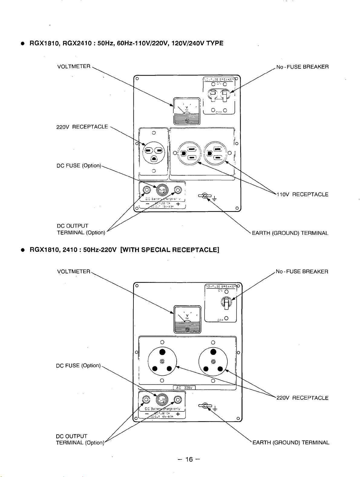
RGXl810, RGX2410
VOLTMETER NO - FUSE BREAKER
220V RECEPTACLE
DC FUSE (Option)
:
50Hz,
60Hz-11 OV/220V, 120V/240V
TYPE
1 1
OV RECEPTACLE
DC OUTPUT
TERMINAL (Option) EARTH (GROUND) TERMINAL
RGXl810,2410 : 50Hz-220V WITH SPECIAL RECEPTACLE]
DC FUSE (Option)
,220V RECEPTACLE
DC OUTPUT
TERMINAL (Option)
-
16-
Page 20
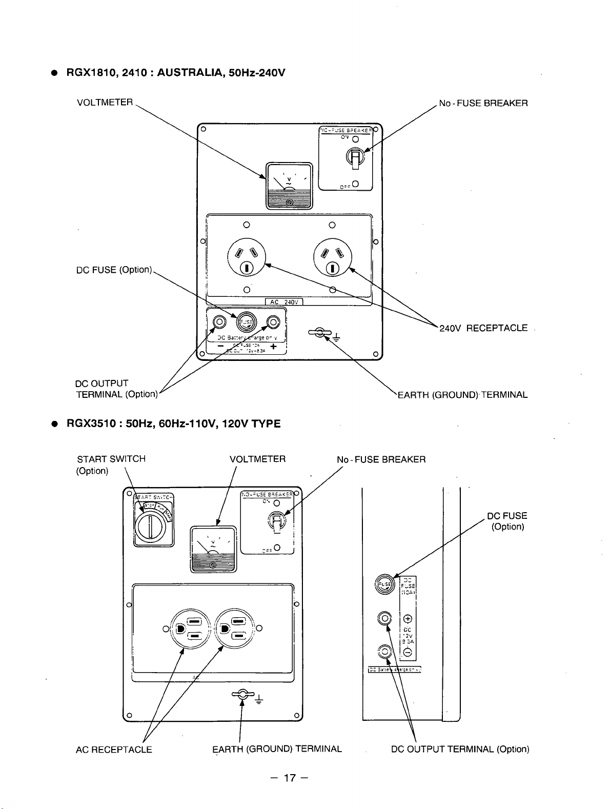
RGX1810,2410 : AUSTRALIA,
50HZ-240V
VOLTMETER
\
DC OUTPUT
TERMINAL (Option)
/
NO - FUSE BREAKER
240V
RECEPTACLE
.
RGX3510
START SWITCH VOLTMETER
(Option)
50Hz,
\
60Hz-1 lOV, 120V
I
TYPE
NO-FUSEBREAKER
/
/
DC FUSE
(Option)
AC RECEPTACLE EARTH (GROUND) TERMINAL
-
17-
DC OUTPUT TERMINAL (Option)
Page 21
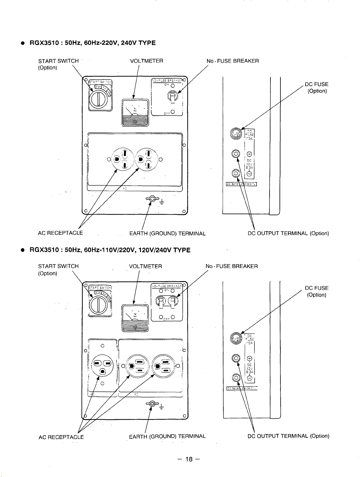
RGX3510 : 50Hz, 60Hz-220VY 240V TYPE
START SWITCH
(Option)
AC RECEPTACLE
\
VOLTMETER
EAR~H
(GROUND)
/
TERMINAL
No -FUSE BREAKER
DC FUSE
(Option)
/
DC OUTPUT TERMINAL (Option)
RGX3510 : 5OHZ, 60Hz-1 10V/22OVy 120V/240V TYPE
START SWITCH
(Option)
\
VOLTMETER
-c
NO-FUSEBREAKER
/
/
(Option)
DCFUSE
AC RECEPTACLE
I
EARTH
(GROUND)
TERMINAL
-
18-
DC
OUTPUT
TERMINAL
(Option)
Page 22
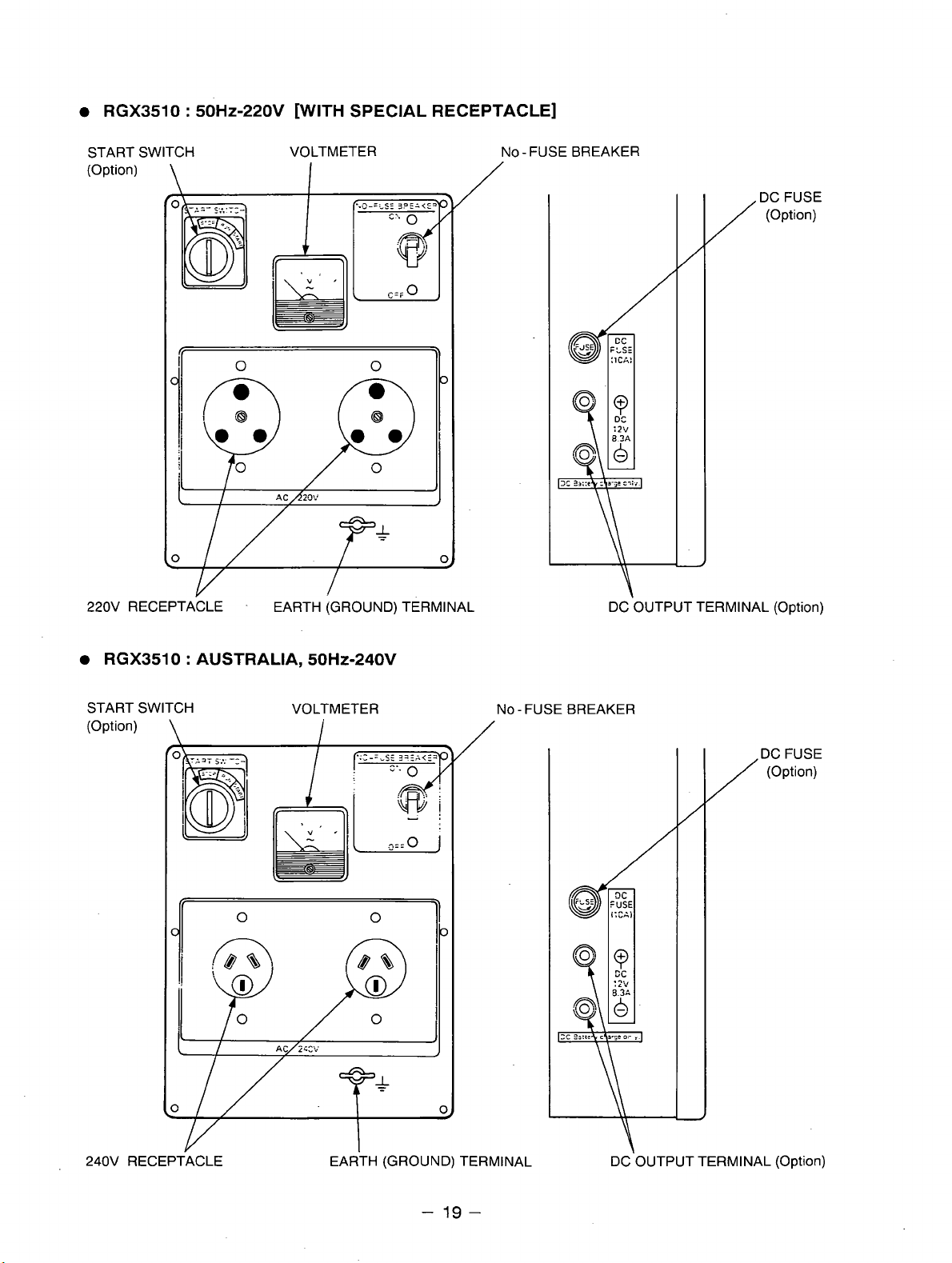
RGX3510
:
50Hz-220V
[WITH SPECIAL RECEPTACLE]
START SWITCH VOLTMETER
(Option)
220v RECEPTACLE
\
-
I
EARTH
(GROUND)
/
TERMINAL
No-FUSEBREAKER
DC'OUTPUT
/Dc
TERMINAL
(Option)
FUSE
(Option)
RGX3510 : AUSTRALIA, 50HZ-240V
START SWITCH VOLTMETER
(Option)
\
0
d
I
i
C
NO - FUSE BREAKER
/
(Option)
/Dc
0
1
FUSE
240V RECEPTACLE EARTH (GROUND) TERMINAL
-
19
-
DC'OUTPUT
TERMINAL
(Option)
Page 23
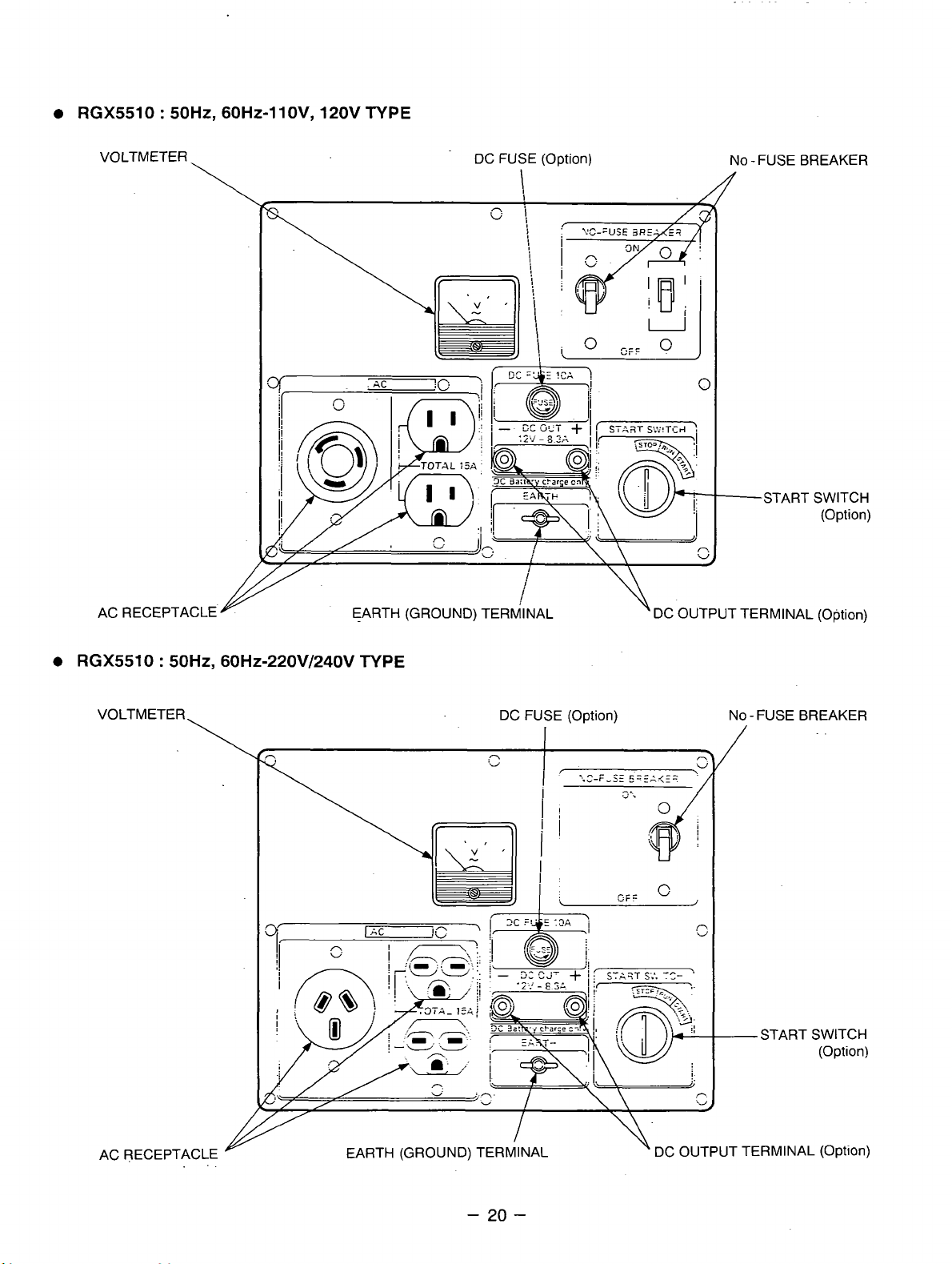
RGX5510 : 50Hz, 60Hz-1 lOV, 120V TYPE
VOLTMETER
\
AC RECEPTACLE
DC FUSE (Option)
EARTH (GROUND) TERMINAL
\DC
f
-
OUTPUT
NO-FUSEBREAKER
START SWITCH
(Option)
TERMINAL
(Option)
0
RGX5510
:
60H~-220V/240V TYPE
DC FUSE (Option)
NO-FUSEBREAKER
I
/
-START SWITCH
(Option)
AC RECEPTACLE
J
EARTH (GROUND) TERMINAL DC OUTPUT TERMINAL
-
20
-
\\
(Option)
Page 24
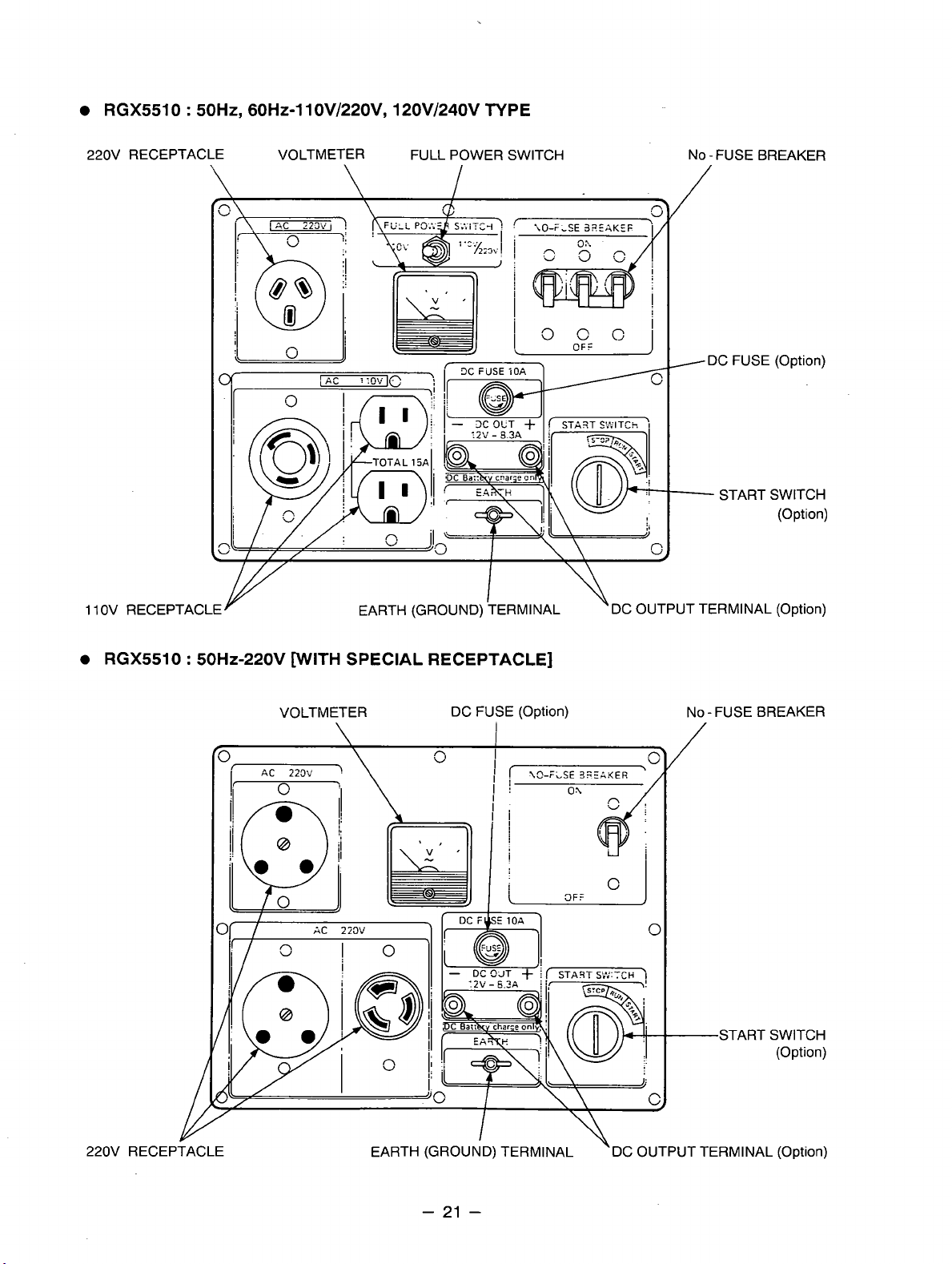
RGX5510 : ~OHZ, 60H~-lIOV/220V, 120V/240V TYPE
220V RECEPTACLE VOLTMETER FULL POWER SWITCH
1 1
OV RECEPTACLE EARTH (GROUND) TERMINAL
I
NO -FUSE BREAKER
DC FUSE (Option)
-
START SWITCH
'
DC OUTPUT TERMINAL (Option)
(Option)
RGX5510 : 50Hz-220V [WITH SPECIAL RECEPTACLE]
VOLTMETER DC FUSE (Option)
NO
-
FUSE BREAKER
/
START SWITCH
(Option)
220V RECEPTACLE
I
EARTH (GROUND) TERMINAL \DC OUTPUT TERMINAL (Option)
-
21
-
Page 25
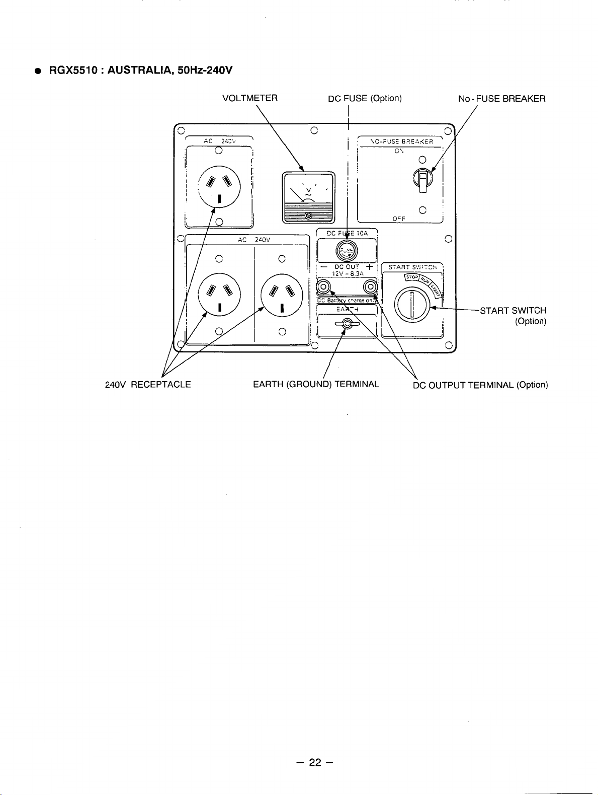
RGX5510 : AUSTRALIA,
50Hz-240V
240V RECEPTACLE
VOLTMETER DC FUSE
\
EARTH
(GROUND)
(Option)
I
TERMINAL
NO-FUSEBREAKER
/
-START SWITCH
(Option)
DC OUTPUT TERMINAL (Option)
-
22
-
Page 26

4-3
LOCATION
of
SERIAL NUMBER
and
SPECIFICATION NUMBER
Serial number and specification number are stamped on the
of control box.
wall
NOTE:
Always specify these numbers when inquiring about the generator or ordering spare parts in
order to get correct parts and accurate service.
LABEL
(MODEL
NAME)
PEL,
stuck on the side
MODEL
NAME
-
23
-
Page 27

5.
CONSTRUCTION AND FUNCTION
5-1
CONSTRUCTION
REAR COVER ROTOR COMPLETE STATOR COMPLETE
MOUNT RIBBER STATOR BOLT BALL BEARING THROUGH BOLT FRONT COVER
5-2
FUNCTION
5-2-1
The stator consists
sheet core, a main coil and a condenser coil which
are wound in the core slots.
The condenser coil excites the rotor field coil
which generates
STATOR
AC
of
a laminated silicon steel
voltage
in
the main coil.
j
'
I
I
!
I
I
I
I
Fig.
5-2
-
24
-
Page 28

5-2-2
One or two condensers are installed in the control
box and are connected to the condenser coil of the
stator.
These condensers and condenser coil regulate the
output voltage.
CONDENSER
i
I
5-2-3
The rotor consists
sheet core and a field coil which
core.
DC
sheet core. Two permanent magnets are provided
for the primary exciting action.
ROTOR
of
a laminated silicon steel
is
wound over the
current in the field coil magnetizes the steel
I
I
!
1
!
Fig.
Fig.
i
I
5-3
i
5-4
A
diode rectifier and surge absorber is mounted inside of the insulator.
'
DIODE RECTIFIER SURGE
ABSORBER
\.=
Fig.
5-5A
-
25
-
Fig.
5-58
Page 29

5-2-4
The
panel protects whole
DC
10
FUSE
ampere
(OPTION)
DC
fuse mounted
DC
circuit from getting
damage by overload or short circuit.
on
the control
I
5-2-5
NO-FUSE BREAKER
The KO-Fuse breaker protects the generator from
getting damage by overloading or short circuit in
the appliance. Table
5-1
shows the capacity of
No-Fuse breaker by each spec. and their object of protection.
MODEL
RGX1810
RGX2410
RGX3510
RGX55
I
50Hz
I
60Hz 220V. 240V
SPECIFICATION
I
1
1 1
OV122OV! 120V.'240V 6.5A (2-Pole. 2-Element)
.
1 1 OVj220V. 120Vi'240V
I
1
50Hz
;
i
!
..
I
60Hz
'1
j
I
I
1 1 OVi220V. 120V,'240V
!
I50Hz
I
!
I
;
!
60HZ
-
50HZ
0
r
i
60Hz 220V. 240V
I
11 OVi22OV, 120Vi240V
I
'
i
1 1 OV/22OV, 120Vi240V
i
i
1 1 OVi220V, 1 20V:240V 22A (2-Pole, 2-Element)
'
NO-FUSE BREAKER
11ov 14A
120v 12A
220v 6.5 A
240V
1 1
ov.
120v 14 A
5.5
I
7A (2-Pole, 2-Element)
11ov 18A
120v
220v
240V 7A
1 1 ovi220v
12OV;240V
llnv
17nv
220v. 2cov
ll0V
120v
"At
I
zzuv
240V
-
"
1 1 ovj220v
120V?'240V 1 OA (2-Pole. 2-Element)
1 1
ov.
120v 27 A
220V!240V
11
ov,
120v
220V, 240V
11
ov,
120v
j
8A (2-Pole, 2-Element)
!
7A (2-Pole, 2-Elexent)
I
!
~~
9A (2-Pole. 2-Element)
I
!
:
12A (2-Pole. 2-Element)
I
I
14A (PPole, 2-Element)
!
!
20A (PPole, 2-Element)
T2S:e
15 A
1
25 A
22 A
-,.
1ZH
10A
14 A
30
20 A
30 A
40 A
30 A
22 A Total output amperage
30 A
5-7
A
7A
8A
RA
. _.
.
9A
1
A
Fig.
5-6
I
OBJECT
of
PROTECTION
I
!
i
1
I
I
:
i
I
Total output amperage
1
I
i
:
!
Total output amperage 40 A
Output from 30A receptacle
Total output amperage
Total output amperage
Output from 30A receptacle
I
I
I
j
Total output amperage
Output from 30A receptacle
Total output amperage
OutDut from 30A receDtacle
i
-
26
-
Page 30

5-2-6
RECEPTACLE
and
AC PLUG (STD.SPEC.)
These are used for taking
varying in rated voltage and current from another, are used. Each model has at least one receptacle to
deliver the rated generator output.
corresponding receptacle: are provided. Table
not to use the receptacles and
up to total
!-,
f@,
\vJ
e,
from two receptacles
.
I
AC
output power from the generator.
As
many AC plugs as the receptacles, each matching the
5-2
shows the rated current for each receptacle. Be careful
AC
plugs beyond the specified amperage limits to prevent burning.
15
amperes
Caution:
A
total of six kinds of receptacles, each
.
To
connect the appliance to locking receptacle,
Insert the plug into the receptacle and turn It
clockwise to lock.
NOTE:
If
your generator has receptacles peculiar to your country, Table
Fig.
5-7
5-2
does not apply.
-
27
-
Page 31

5-3 GENERATOR OPERATION
PERMANENT MAGNET
FOR
INITIAL EXCITATION
DIODE
STATOR MAIN COIL
,-
ECEPTACLE
APPLIANCE
CONDENSER COIL
CONDENSER
Fig.
5-8
5-3-1 GENERATION
Of
NO-LOAD VOLTAGE
IVhen the generator starts running: the permanent magnet built-in to the rotor generates 3 to
AC
voltage in the main coil and condenser coil wound on the stator.
As
one or two condensers are connected to the condenser coil, the small voltage at the condenser
coil generates a minute current
:z.
which flows through the condenser coil. At this time, a small flux
is produced with which the magnetic force at the rotor’s magnetic pole is intensified.When this
magnetic force is intensified, the respective voltages in the main coil and condenser coil rise up.
As
the current
!$$
increases, the magnetic flux at the rotor’s magnetic pole increases further. Thus the
voltages at the main coil and condenser coil keep rising by repeating this process.
As AC
This
coil circuit rectifies this
current flows through the condenser coil, the density of magnetic flux in the rotor changes.
change
of
magnetic flux induces
AC
voltage into
AC
voltage in the field coil, and the diode rectifier in the field
DC.
Thus a
DC
current
;s
flows through the field coil and
magnetizes the rotor core to generate an output voltage in the main coil.
When generator speed reaches
rpm (50Hz type) or
3000
to
3300
rpm (60Hz type), the
2700
to
2800
current in the condenser coil and field coil increases rapidly.
If
This acts to stabilize the output voltage of each coils.
generator speed further increases to the rated
value, the generator output voltage will reach to the rated value.
5-3-2 VOLTAGE FLUCTUATIONS UNDER LOAD
When the output current flows through the main coil to the appliance, a magnetic flux is produced and
serves to increase current
flux across the rotor core rises.
-
Eenerator output voltage is prevented from decreasing.
:$$
in the condenser coil. When current
As
a result, the current flowing in the field coil increases and the
i@
increases, the density of magnetic
6V
of
-
28
-
Page 32
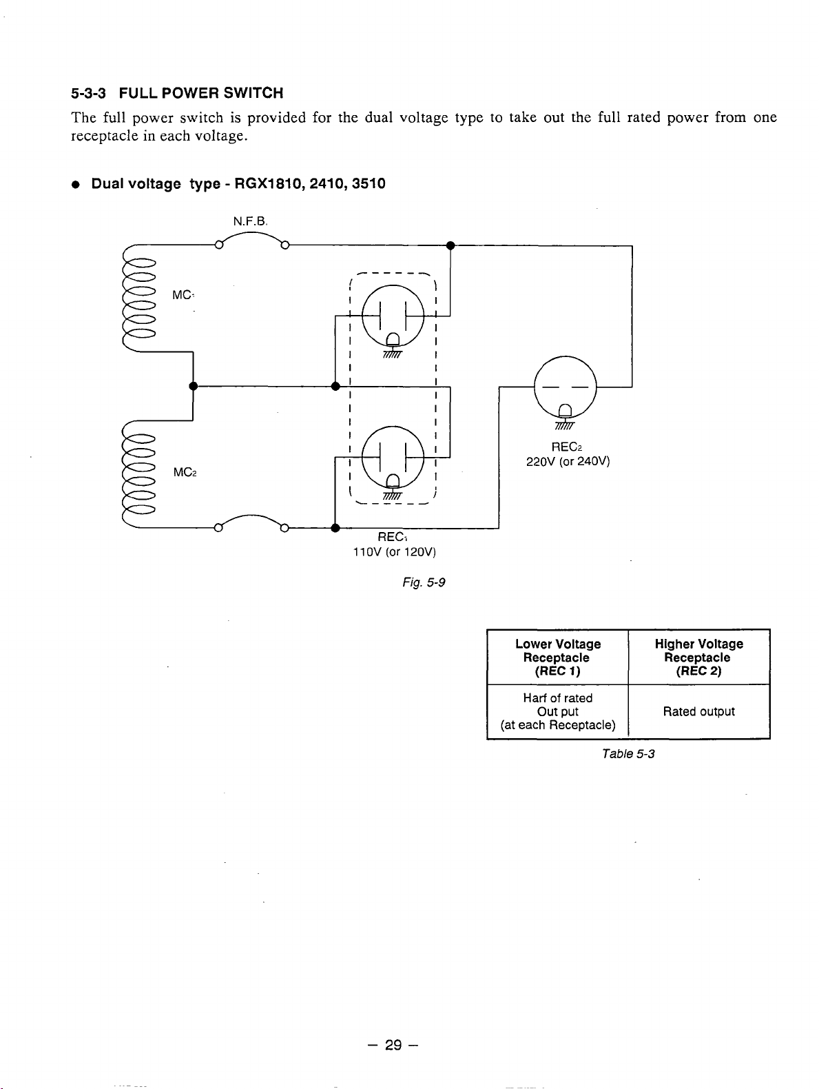
5-3-3
FULL
POWER
SWITCH
The full power switch is provided for the dual voltage type to take out the full rated power
in
receptacle
0
Dual
each voltage.
voltage
type
-
RGX1810,2410,3510
N.F.B.
*
""_
-Qj-
k
I
-Q+
"""
I
RECr
220V
(or
240V)
from
one
11
OV
REC:
(or
120V)
Fig.
5-9
I
Lower Voltage
Receptacle
(REC
1)
Harf
of
rated
out put
(at each Receptacle)
I
Table
Higher Voltage
Receptacle
(REC
Rated output
5-3
I
2)
-
29
-
Page 33
0
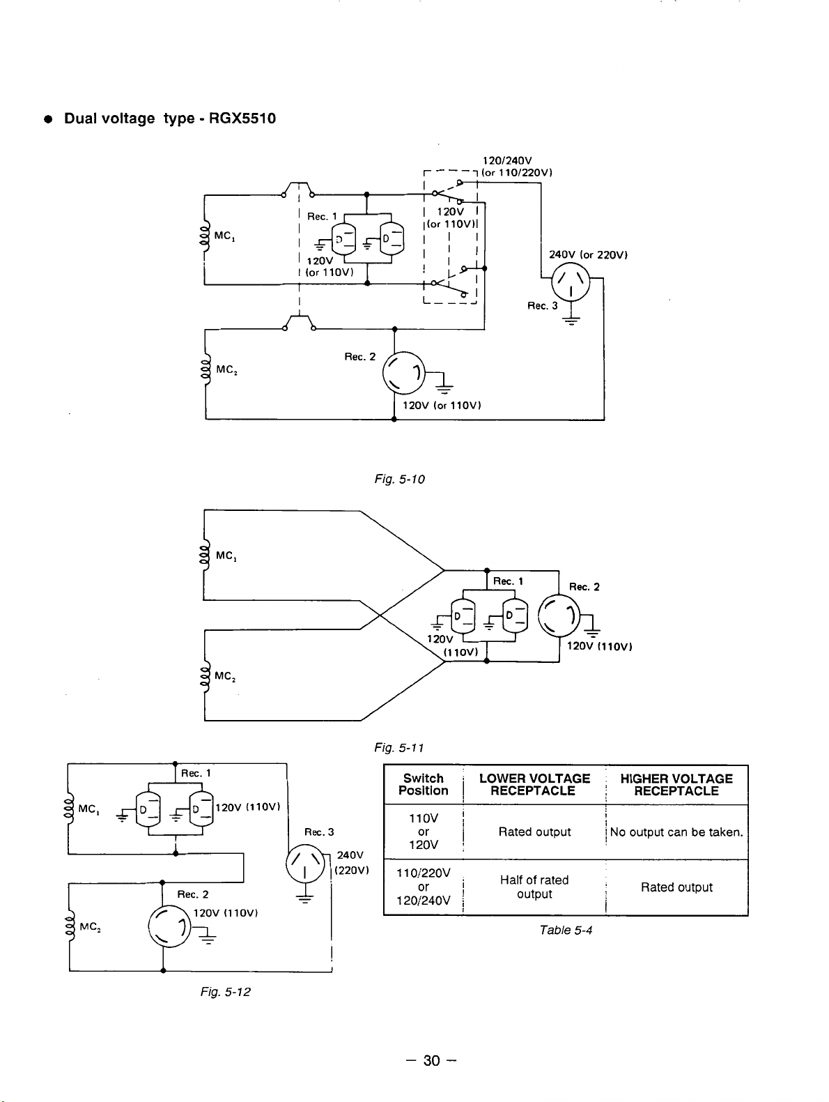
Dual voltage type
-
RGX5510
I
Fig.
120V
5-
10
r
(or
- - -
llOV1
120/24ov
i
(or
110/22OVl
240V
(or
22OVl
-
Ret.
1
Fig.
-
Ret.
r
I
MC,
1
i
5- 1 1
Switch
Position
11ov
or
120v
110:'220v
120/24OV
i
LOWER VOLTAGE HIGHER VOLTAGE
I
RECEPTACLE
'
I
Rated output
;
,
Half of rated
output
Table
Rec.
5-4
2
;
I
i
No
output
:
i
RECEPTACLE
can
be taken.
Rated output
Fig.
5-
12
-
30
-
Page 34
Two
main coils are wound over stator core. Each main coil outputs half the rated power at the lower
voltage (llOV or 120V). These main coils are wound to be in the same phase. The full power switch
reconnects these main coils in parallel or in series.
Fig. 5-9 shows a circuit diagram.When the full power switch is set for single lower voltage indication
is
(llOV or 120V), the switch position
simplified representation of this circuit, showing the two main coils connected in paralle1.h this case, the
higher voltage (220V or 240V) at Rec.
to the rated power (up to 30A if the rated current is over
When the full power switch is set for double voltage indication (llOV/220V or 120V/240V), the switch
position is as indicated by the upper dotted line in Fig. 5-9. Fig. 5-11 is a simplified representation of this
circuit, showing the two main coils connected in series.
from the receptacles for the both voltages. Rec.
1
but Rec.
Table 5-4 is a summary
accordance with the appliance to be used.
and Rec. 2 for the lower voltage can output only up
of
the above explanation. Select the proper output voltage by full power switch in
as indicated by the lower solid line in the diagram. Fig. 5-10 is a
3
cannot be taken out. Rec. 2 for the lower voltage can output up
30A),
3
for the higher voltage can output up to the rated power,
and Rec. 1 can output up to a total of 15A.
In
this case, power can be taken simultaneously
to
half the rated power each.
-
31
-
Page 35
5-4
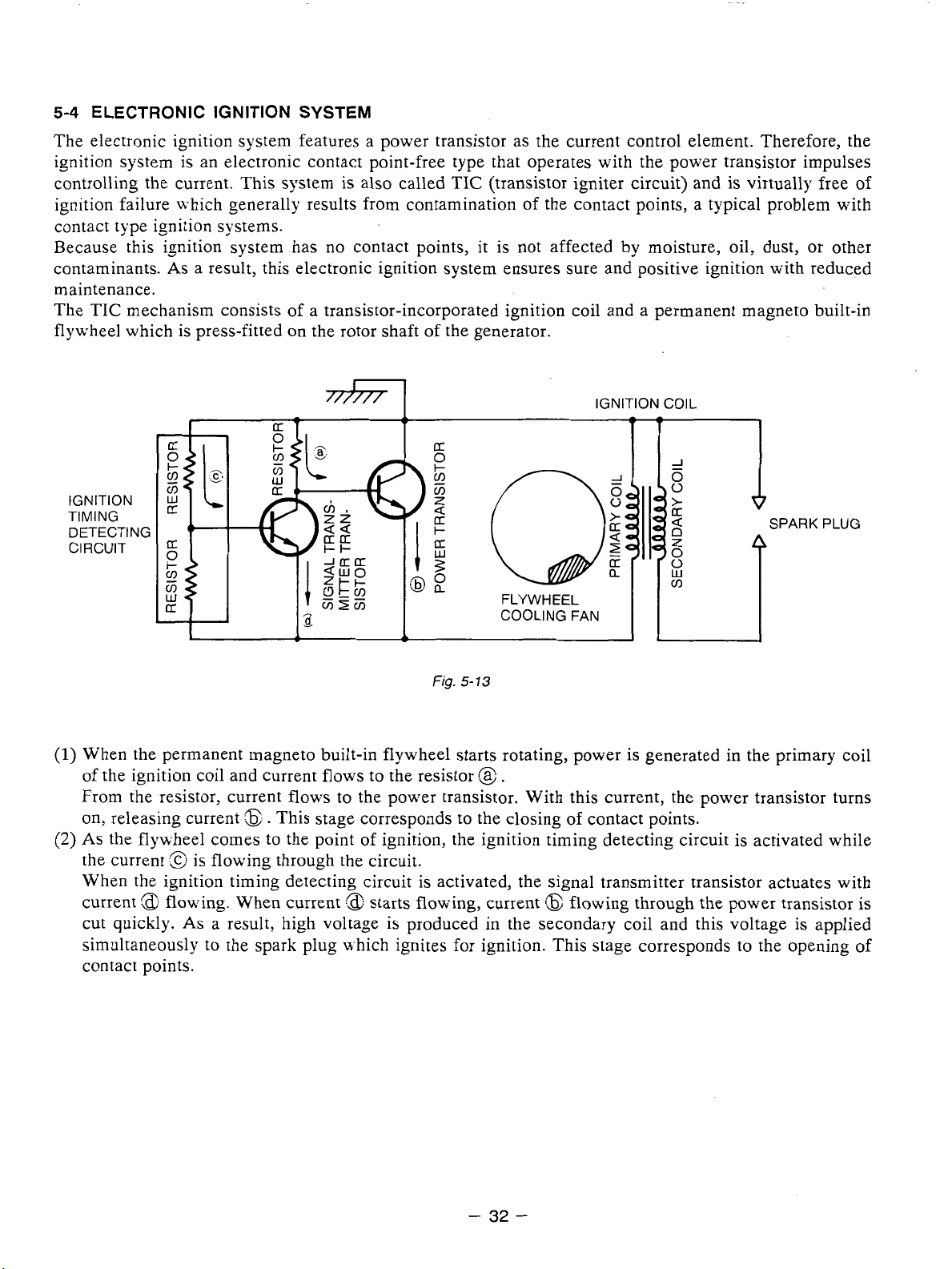
ELECTRONIC IGNITION SYSTEM
The electronic ignition system features a power transistor as the current control element. Therefore, the
ignition system is an electronic contact point-free type that operates with the power transistor impulses
controlling the current. This system is also called TIC (transistor igniter circuit) and is virtually free of
ignition failure n-hich generally results from contamination of the contact points, a typical problem with
contact type ignition systems.
it
Because this ignition system has no contact points,
As
contaminants.
maintenance.
TIC
The
flywheel which is press-fitted on the rotor shaft of the generator.
mechanism consists of a transistor-incorporated ignition coil and a permanent magneto built-in
a result, this electronic ignition system ensures sure and positive ignition with reduced
is not affected by moisture, oil, dust, or other
IGNITION
TIMING
IGNITION
FLYWHEEL
I
I:
COOLING FAN
COIL
i
(1)
When the permanent magneto built-in flywheel starts rotating, power is generated in the primary coil
of the ignition coil and current flows to the resistor
From the resistor, current flows to the power transistor. With this current, the power transistor turns
on, releasing current
(2)
As
the flywheel comes to the point of ignition, the ignition timing detecting circuit is activated while
:@
the current
\;hen the ignition timing detecting circuit is activated, the signal transmitter transistor actuates with
current
cut quickly.
simultaneously to the spark plug n-hich ignites for ignition. This stage corresponds to the opening
contact points.
:$$
is flowing through the circuit.
flowing. When current
As
:B..
This stage corresponds to the closing
:a:
starts flowing, current
a result, high voltage is produced in the secondary coil and this voltage is applied
13
.
of
contact points.
(3
flowing through the power transistor is
PLUG
of
-
32
-
Page 36
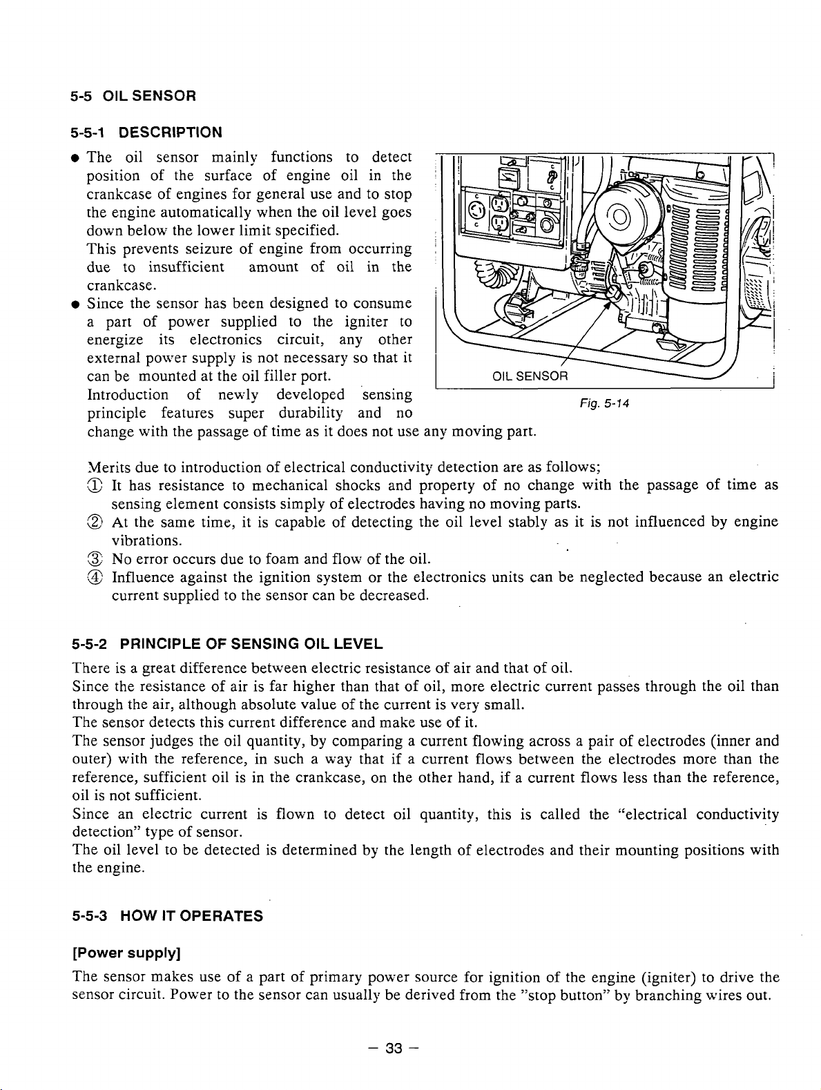
5-5
OIL SENSOR
5-5-1
0
DESCRIPTION
The oil sensor mainly functions
position of the surface
of
to
detect
engine oil in the
crankcase of engines for general use and to stop
the engine automatically when the oil level goes
down below the lower limit specified.
of
This prevents seizure
engine from occurring
due to insufficient amount of oil in the
crankcase.
0
Since the sensor has been designed to consume
a part of power supp1ie.d to the igniter to
energize its electronics circuit, any other
so
external power supply is not necessary
can be mounted at the oil filler port.
that it
I
OIL
SENSOR
Introduction of newly developed sensing
principle features super durability and no
change with the passage of time as it does not use any moving part.
Merits due to introduction of electrical conductivity detection are as follows;
:z
It
has resistance to mechanical shocks and property of no change with the passage of time as
sensing element consists simply of electrodes having
A
&
At the same time, it is capable
of
detecting the oil level stably as it is not influenced by engine
no moving parts.
vibrations.
:z
No
n
&
error occurs due to foam and flow of the oil.
Influence against the ignition system or the electronics units can be neglected because an electric
current supplied to the sensor can be decreased.
Fig.
5-14
5-5-2
PRINCIPLE
OF
SENSING OIL LEVEL
There is a great difference between electric resistance of air and that of oil.
Since
re.sistance
of
air is far higher than that of oil, more electric current passes through the oil than
the
through the air, although absolute value of the current is very small.
The sensor detects this current difference and make use of it.
The sensor judges the oil quantity, by comparing a current flowing across a pair of electrodes (inner and
outer) with the reference, in such a way that if a current
flows
reference, sufficient oil is in the crankcase, on the other hand, if a current
between the electrodes more than the
flows
less than the reference,
oil is not sufficient.
Since an electric current is flown to detect oil quantity, this is called the "electrical conductivity
detection" type of sensor.
The oil level to be detected is determined by the length of electrodes and their mounting positions with
the engine.
5-5-3
[Power
HOW
IT OPERATES
supply]
The sensor makes use of a part of primary power source for ignition of the engine (igniter) to drive the
sensor circuit. Power to the sensor can usually be derived from the "stop button" by branching wires out.
-
33
-
Page 37
[Judgement
When sufficient oil is in the crankcase, both
which current
of
oil level]
flows
of
inner and outer electrodes are immersed in the oil through
across the electrodes. The sensor judges that oil in the crankcase is sufficient.
\%'hen oil level goes down and the inner electrode is exposed to the air due to consumption of oil, no
current
flow between the electrodes as air is considered to be electrically non-conductive.
The sensor in this case judges that oil is insufficient.
[Decision
of
oil shortage]
Oil level at the electrodes may go down momentarily probably due to the engine being slanted or affected
by vibration even if a sufficient oil is in the crankcase.
For that reason, the sensor has an electronic timer circuit to prevent it from- interpreting as short of oil
is
when amount of oil
sufficient. The sensor has been designed
when oil-shortage is detected for
5
seconds uninterrupted.
so
that the engine is
LO
be stopped only
The timer emplovs an integration circuit and it is to be reset when the inner electrode is soaked in the oil
again before the sensor decides it as oil-shortage.
The oil level where the sensor decides as oil-shortage, when oil level goes down gradually, is called
"threshold level".
[Automatic stop
of
engine]
When rhe sensor decides as oil-shortage, it makes the engine to stop running automatically for protection
of engine.
is
Once the stopping circuit
activated, it keeps functioning until it confirms that the engine has made a
complete stop, then the circuit stops functioning automatically.
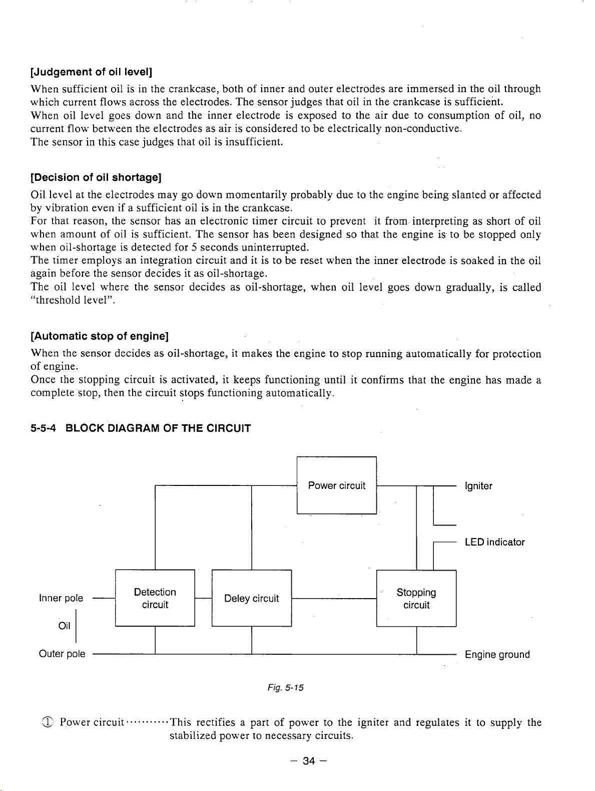
5-5-4
BLOCK
DIAGRAM
OF
THE
CIRCUIT
Power circuit
Igniter
-
-
1
Inner pole
oil
Outer pole Engine ground
/"
:
1:
Po\\:er circuit
u
-
I
Detection
circuit
-.
-
Deley circuit
Fig.
5-
15
*
This rectifies a part of power to the igniter and regulates it to supply the
Stopping
circuit
LED indicator
stabilized power to necessary circuits.
-
34
-
Page 38
n
!&
Detection circuit-......
n
&
Delay circuit
.n
&
Stopping circuit.
This detects quantity of oil, sufficient or not, according to difference of
electric resistance across inner and outer electrodes.
a. e.
-
This his prevents the sensor from making an unnecessary stop of the engine
by momentary lowering of the oil level due to the engine being slanted or
affected by vibration in spite of sufficient oil in the crankcase.
* . *
*
+
-
This automatically stops the engine running.
Also, the LED indicator for warning can be lit &hile the engine is being
stopped. We have the wires to be connected to LED available.
5-5-5
(1)
CAUTIONS TO BE TAKEN ON HANDLING THE SENSOR
Oil sensor unit
a
Be sure not to damage each wire.
Broken or short-circuited power supply wires andior a grounding wire in particular may lead to
malfunction or breakdown.
A
i&
The sensor is
not
interchangeable from engine to engine because the sensor is to be exclusively
installed individually in each engine employed.
(2)
Mounting and wiring of oil sensor unit
A
:&
Although this has been designed to have enough anti-noise properties in practical use, do not route
the sensor wirings in the vicinity of noise-generating sources such as ignition plugs or high voltage
cords. This may cause malfunction or breakdown.
n
Since capacity of power source
is
limited, current flown in the electronic circuit of the sensor is
kept as low as possible.
Be sure to use terminals with a high contact reliability of more than that of tinned terminals.
(3)
Operation
n
:&
If
operating with the engine kept tilted, oil surface inside of the engine varies and the correct oil
of
oil sensor
level can not to be detected which in turn obstructs the preventing function of engine seizure.
Operate the engine by keeping it level.
n
.&
When starting the engine with an insufficient oil in the crankcase, engine starts once then it stops
automatically after it runs for 5 seconds.
A
When the engine has been stopped by the oil sensor, voltage remained in the electronic circuit
3
prevents the sensor from being re-started for
to
Try
re-start the engine after 3 seconds or more.
-
seconds after the engine stop.
35
-
Page 39

SAFETY
6.
Use extreme caution near-fuel. A constant danger of explosion or fire exists.
1.
Do not fill the fuel tank while the engine is running.
tank. Be careful not to spill fuel when refueling.
Do
2.
not place inflammable materials near the generator.
PRECAUTIONS
Do
not smoke or use opern flame near the fuel
If
spilt, wipe it and let dry before starting the engine.
Be careful not to put fuel, matches, gunpowder, oily cloth, straw, and any other inflammables near the
Y
generator.
Do
3.
not operate the generator
in
a roomycave or tunnel. Always operate
in
a well-ventilated area.
Otherwise the engine may overheat and also: the poisonous carbon monoxide contained in the exhaust
-
gases will endanger human lives. Keep the generator at least
1 m (4
feet) away from structures or
facilities during use.
4.
Operate
If
the generator is tilted or moved during use: there is a danger of fuel spillage and a chance that the
-
generator may tip over.
5.
Do
the
generator on a level surface.
not operate with wet hands or
in
the rain.
Severe electric shock may occur. If the generator is wet by rain or snon-, wipe it and thoroughly dry it
before starting.
Don't pour water over the generator directly nor wash it with water.
is
If the generator
wet with water, the insulations will be adversely affected and may cause current
leakage and electric shock.
6.
Do
not connect the generator to the commercial power lines.
This may cause a short-circuit or damage to the generator.
Use a transfer switch (Optional parts) for connecting with indoor wiring.
NOTE: The parts numbers of the transfer switches and of the plastic box to store them are
shown in Table
Part No. Part Name
367-43008-08
348-43009-08
7.
Use a fuse of the correct capacity.
If
the generator rpm is increased excessively in the overload condition
6-1.
I
Q'ty j Phase I Allowable Current
Pkstic
Box
I
Plastic
Bcx
(DC
(lid
111
T&le
6-
1
output)
!
30A
60A
by
using an over rated fuse, the
I
generator may be burnt.
CAUTION
:If the fuse is burnt or the circuit breaker tripped
appliance,the cause can be an overload or a short-circuit.
In such a case, stop operation immediately and carefully check the electrical
appliance and
AC
plugs for faulty wiring.
off
as a result of using an electrical
as
-
36
-
Page 40
7.
RANGE
OF
APPLICATIONS
Generally, the power rating of an electrical appliance indicates the amount of work that can be done by it.
The electric power required for operating an electrical appliance is not always equal to the output wattage
of the appliance. The electrical appliances generally have a label showing their rated voltage, frequency,
and power consumption (input wattage). The power consumption of an electrical appliance is the power
necessary for using it. When using a generator for operating an electrical appliance,the power factor and
starting wattage must be taken into consideration.
In
order to determine the right size generator, it is necessary to add the total wattage of all appliances to
be connected to the unit.
by
Refer to the followings to calculate the power consumption of each appliance or equipment
(1)
Incandescent lamp, heater, etc. with a power factor of
1
.O
its type.
Total power consumption must be equal
Example:
(2)
Fluorescent lamps, motor driven tools, light electrical appliances, etc. with a smaller power
factor
A
rated
3OOOW
generator can turn thirty lOOW incandescent lamps
to
or less than the rated output
of
the generator.
on.
Select a generator with a rated output equivalent to 1.2 to 2 times of the power consumption of the
load.
Gemrally the starting wattage
of
motor driven tools and light electrical appliances are 1.2 to 3 times
lager than their running wattage.
Example:
NOTEI: If a power factor correction capacitor is not applied to the fluorescent lamp, the more
NOTE2: Nominal wattage of the fluorscent lamp generally indicates the output wattage of the
(3)
Mercury lamps with a smaller power factor
Loads for mercury lamps require 2
Example:
A
rated
250W
power shall be required to drive the lamps.
lamp.
Therefore,. if the fluorescent lamp has no special indication as to the power consumption,
efficiency should be taken into account as explained in Item
A
A
~
4OOW
rated
30001%'
electric drill requires a
to
3
times the indicated wattage during start-up.
mercury lamp requires
generator can power two or three
800W
400W
generator to start it.
(5)
on the following page.
to 1200W power source to be turned
40014'
mercury lamps.
on.
(4)
Initially loaded motor driven appliances such as water pumps,compressors,etc.
These appliances require large starting wattage which is 3 to 5 times of running wattage.
Example:
NOTEI: Motor-driven appliances require the aforementioned generator output only at the starting.
NOTE2: Motor-driven appliances mentioned in Items
A
rated 9OOW compressor requires a
Once their motors are started, the appliances consume about 1.2 to
power consumption
for other electrical appliances.
starting power depending on the kind of motor and start-up load. If
determine the optimum generator capacity, select a generator with a larger capacity.
so
that the excess power generated by the generator can be used
-
37
-
4500W
generator to drive it.
(3)
and
(4)
vary in their required motor
2
times their rated
it
is difficult to
Page 41
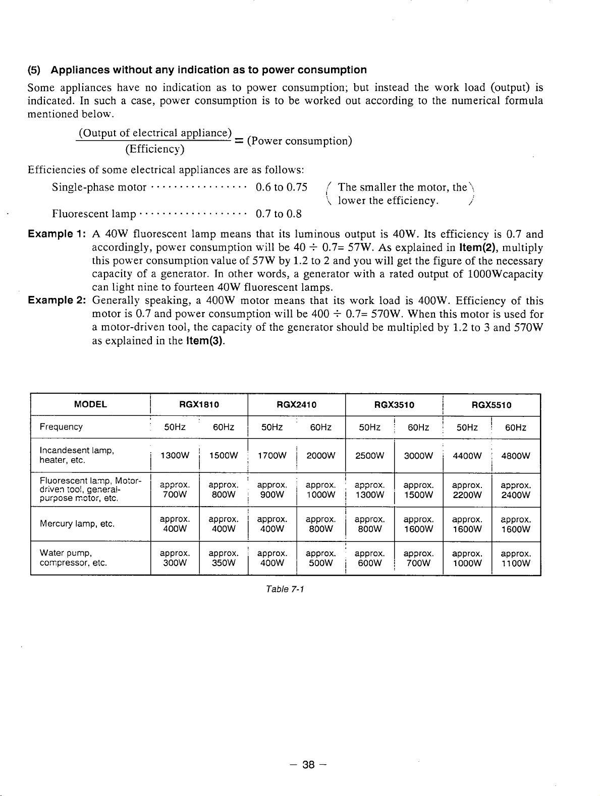
(5)
Appliances without any indication as to power consumption
Some appliances have no indication as to power consumption; but instead the work load (output) is
is
indicated. In such a case, power consumption
mentioned below.
to be worked out according to the numerical formula
(Output of electrical appliance)
(Efficiency)
Efficiencies of some electrical appliances are as follows:
Single-phase motor
Fluorescent lamp . .
Example 1 :
Example 2:
Frequency
A
accordingly, power consumption will be 40
this power consumption value of
capacity of a generator. In other words, a generator with a rated output of 1OOOWcapacity
can light nine to fourteen
Generally speaking, a 400W motor means that its work load is
motor is
a motor-driven tool, the capacity of the generator should be multipled by
as explained in the
MODEL
40W
- - * - . - * - - * -
.
. . . . . . . . . . . . . .
fluorescent lamp means that its luminous output is 40W. Its efficiency is 0.7 and
0.7
and power consumption-will be 400
Item(3).
i
RGX1810
I
'
50Hz 60HZ
=
(Power consumption)
-
0.6
to
. .
0.7
to
571%'
by
40W
fluorescent lamps.
RGX2410
i
50HZ 60Hz
0.75
0.8
1.2
'
The smaller the motor, the;;
'i
lower the efficiency.
+
0.7= 57W.
to 2 and you will get the figure of the necessary
+
0.7=
As
570W.
RGX3510
50Hz
explained in
400W.
When this motor is used for
i
;
60Hz 50Hz
i
Item(2),
Efficiency of this
1.2
:
multiply
to 3 and 570W
RGX5510
I
!
60Hz
lncandesent lamp,
heater, etc.
Fluorescent
driven
purpose
Mercury lamp, etc.
Wate:
coqressor. etc.
laq.
rw1,
geserai-
IYCtOi,
pump.
etc.
Pvlo3r-
'
1300W 1500W
I
I I
approx. approx.
I
400W
approx.
i
I
400W
approx. approx.
350W
I
I
1700W 2000W
:
approx.
I
400W
I
400W
Tzble
approx.
I
I
approx. ' approx. I approx. approx. approx.
I
7-1
800W
500W 600W
I
2500W
i
'
approx.
1
800W
I
3000W i 4400W 4800W
I
approx.
I
1600W I 1600W I 16OOW
I
700W
I
approx. approx.
I
lOOOw
I
I
1100W 300W
I
I
-
38
-
Page 42

NOTES: Wiring between generator and electrical appliances
1.
Allowable current of cable
Use a cable with an allowable current that is higher than the rated input current of the load
(electrical appliance). If the input current is higher than the allowable current of the cable used, the
cable will become excessively heated and deteriorate the insulation, possibly burning it out.
Table 7-2 shows cables and their allowable currents for your reference.
2.
Cable length
If a long cable is used, a voltage drop occurs due to the increased resistance in the conductors
decreasing the input voltage to the load (electrical product). As a result, the load can be damaged.
Table 7-2 shows voltage drops per
area
Sectional
mm2
I
Gauge No.;
No.i'mm
i
0.75
2.0
5.5
7
I
12 50i0.18 1.486
'
17
23
:
I
3010.18
37/0.26
45 / 0.32
,
100
meters of cable.
.
Resistance
Ohm/100 m 11Ai3A
!
1
.OV
0.51
7
0.332
Table 7-2
j
I
I
Voltage drop per
5AI
12.5V 8V 2.5V 2.477
7.5V
5V 1.5V 1.25
5.0V
3V
lVb
2.5V
2Vi
1.5V
I
-
8A 8A
12V
12V 15V 18V
8V
8Vi
4V
2.5V
100
m
10A j 12A
10A 12A
I
15V 18V
!
10V
1OV
5V
5V
3.5q
12V
12V
6.5V
6.5V
4V
I
15A
15V
7.5V
5V
Voltage drop indicates as V
R mens resistance
=
(
0
/lo0
I means electric current through the wire
i
means the length of the wire
XRXIXl
-
100
m) on the above table.
(A).
(m).
The length of wire indicates round length,it means twice the length from generator to electrical tools.
-
39
-
Page 43

MEASURING PROCEDURES
8.
8-1
MEASURING INSTRUMENTS
8-1-1
"Dr.
ROBIN" GENERATOR TESTER
The "Dr. Robin" generator tester is exclusively
designe.d for fast, easy diagnosis and repair of
Robin generators.
The "Dr. Robin" has the following features:
(1)
Functions of voltmeter, frequency meter,
meggertester, capacitance meter and circuit
tester are combined in one unit.
(2)
Fast and easy readout
(3)
Built-in automatic battery checker indicates
to
the time
(4)
Tester and accessories are installed in a
change batteries.
by
digital indicator.
handy, sturdy case for easy carring.
0
SPECIFICATIONS
I
Model
I
I
!
.:.
Dr.
Robin
Fig.
8-1
I
Pari Number 388-37565-08
Voltage
a,I
O!
%
I
Frequency
m:
K
I
Resistance
.-
L!
i
Condenser Capacity
'
i
-
Insulation Resistance
Circuit Proiector
Power Sosrce 2
Accessories
Dimensions
Weight
(L x W
X
H) 285 mmx200 rnmxl10 mrn
I
i
i
I
I
I
..
i
x
:
Tesi leads with needie probes
I
1
Test leads with jack plugs
Table
8-1
0-500V AC
25-70HZ
0.1
-1,999
10-1
00
314
Fuse
6F44P (006P)
1.6kg
0
Dry
0
.Q
F
Cell Battery
. . .
1 sei
. . . .
. .
1
set
The "Dr. Robin"generator tester can be ordered from Robin generator distributors by the following part
number.
I
Dr.
Robin
If
you do not have a "Dr. Robin"generator tester,use the instruments described
Part
Sumber
:
388-37565-08
I
for checking generator parts.
-
40
-
in
the following section
Page 44

8-1-2
(1)
INSTRUMENTS
VOLTMETER
AC voltmeter is necessary.The approximate
AC voltage ranges
of
the voltmeters to be
used for various types of generators are as
follows:
0
to 15OV: Type with an output voltage
110
or
120V
0
to 3OOV: Type with an output voltage
220,230 or 240V
0
to EOV, 0 to 33OV: Dual voltage type
(2)
AMMETERS
AC ammeter is necessary. An AC ammeter
that
with a range
the current rating
can be changed according to
of
a given generator is most
desirable. (About 10AJ 20AJ 100A)
of
of
!
j
a.
..
.
I
!
:
e
/.
;G@\
G
4
5
3
FOR
Fig.
i
AC
8-2
.
..
i
I
(3)
FREQUEXCY METER
Frequency range
NOTE:
Be careful of the frequency meter's
input voltage range.
:
About 45 to 65Hz
FOR
Fig.
Fig.
AC
8-3
8-4
-
41
-
Page 45

(4)
CIRCUIT TESTER
Used for measuring resistance, etc.
MEGGER TESTER
for
Used
resistance.
Select
measuring generator insulation
.
one
Kith testing voltage range of
5oov.
1
Fig.
!
8-5
(6)
TACHOMETER
Use
the contactless type tacho meter.
i
I
Fig.
Fig.
J
8-6
8-7
-
42
-
Page 46

8-2
AC OUTPUT MEASURING
Use
a circuit like the shown in Fig.8-8 for measuring AC output. A hot plate or lamp with a power factor
of
1.0
may be used as a load. Adjust the load and rpm. and check that the voltage range is as specified in
Table 8-2 at the rated amperage and rated rpm.
Rated
voltage
11ov
120V
I
220V
I
240V
Voltage
8-3
DC OUTPUT MEASURING
To
DC
Measurement of DC output
range
4
Terminal
107
-
is
executed with the switch turned
by adjusting the load to the generator.
is
output
normal.
11
9V
117-13OV
Table
8-2
I
215-238V
-
Fig.
8-9
If
the voltage is within the range from
I
d0
sw
OK
while the current
235-26QV
Load
6V
is
regulated at 8.3A
to
14V,
the voltage
Note : If a battery is connected as a load to the generator, the
approximately
the battery.
1
to
2V.
Therefore, carefully observe the electrolyte level and do not overcharge
-
43
-
DC
output voltage will increase
by
Page 47

8-4
MEASURING INSULATION RESISTANCE
Use a "Dr. Robin'' generator tester in megger
tester mode or use a megger tester to check the
insulation resistance. Connect a megger tester
one
of
receptacle output terminals and the ground
to
terminal, then measure the insulation resistance.
An
insulation resistance
of
1
megohm or more
is
normal. (The original insulation resistance at the
time
of
shipment from the factory
is
10
megohm
or more.)
If
it
is
less than
-
generator and measure the insulation resistance of
1
megohm, disassemble the
the stator, rotor and control panel individually.
~~ ~
Fig.
8-
IO
..
0
STATOR
(1)
Measure the insulation resistance between
"....
BLUE lead and the core.
(2)
Measure the insulation resistance between
WHITE lead and the core.
(3)
Measure the insulation resistance between
YELLOW lead and the core.
(4)
Measure the insulation resistance between
BROWS lead and the core.
0
ROTOR
Measure the insulation across one of the soldered
terminals
of the rotor and the core.
Fig.
8-
1
1
Fig.
8-12
-
44
-
Page 48

0
CONTROL PANEL
Measure the insulation resistances between the
live parts and the grounded parts.
Any
part where the insulation resistance is less than
leakage and electric shock.
Replace the faulty part.
lMQ
Fig.
8-13
has faulty insulation, and may cause electric
i
-
45
-
Page 49
9.
CHECKING FUNCTIONAL MEMBERS
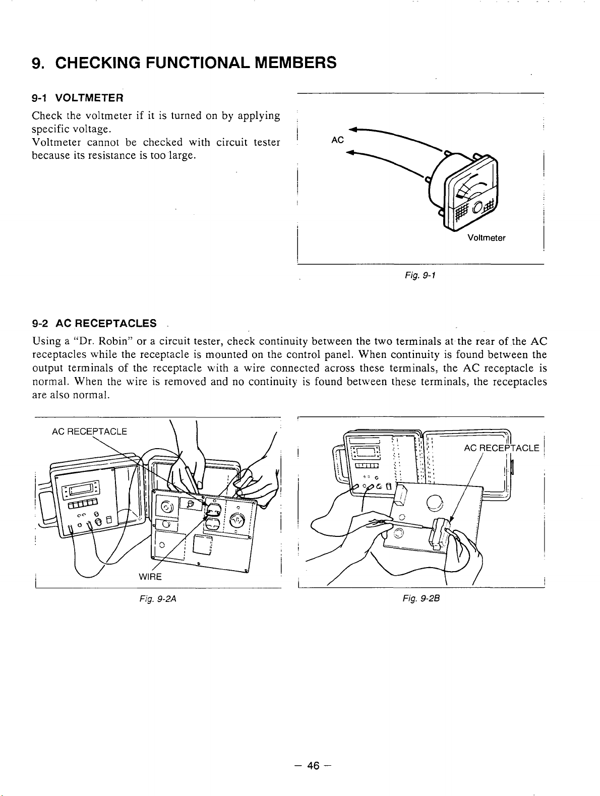
9-1
VOLTMETER
Check the voltmeter
specific voltage.
Voltmeter cannot be checked with circuit tester
if
it
is
turned
on
by applying
i
!
AC
because its resistance is too large.
I
i
9-2
AC RECEPTACLES
i
Fig.
9-1
.
Voltmeter
Using a "Dr. Robin" or a circuit tester, check continuity between the two terminals at the rear
receptacles while the receptacle
output terminals of the receptacle with a wire connected across these terminals: the
normal. When the wire
is
is
mounted
on
the control panel. When continuity
removed and no continuity
is
found between the
AC
is
found between these terminals, the receptacles
are also normal.
of
the
receptacle
I
AC
is
AC RECEPTACLE
\
F/c;. 9-2A
Fig.
9-26
-
46
-
Page 50
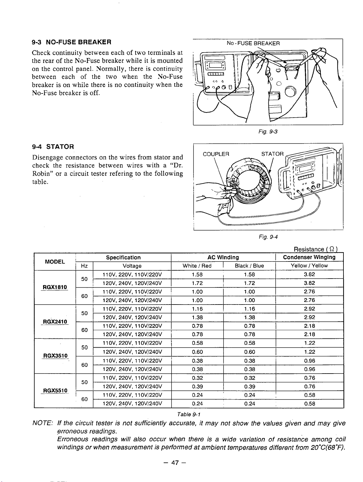
9-3
NO-FUSE
BREAKER
Check continuity between each of two terminals at
is
the rear of the No-Fuse breaker while it
on
the control panel. Normally, there is continuity
between each
breaker is
of the two when the 30-Fuse
on
while there
is
no
continuity when the
mounted
No-Fuse breaker is off.
9-4
STATOR
NO-FUSEBREAKER
Fig.
9-3
I
Disengage connectors
on
the wires from stator and
check the resistance between wires with a "Dr.
Robin" or a circuit tester refering to the following
table.
MODEL
RGX1810
RGX2410
RGX3510
RGX5510
Hz
50
60
50
60
50
60
50
60
Specification
I
I
1 1
i
12OV, 240V, 12OVi24OV
i
11
j
,
12OV, 24dV, 12OVl24OV
1
11
120V, 240V, 1 20Vi240V
1 1
120V, 240V, 12OVi24OV
1 1 ov, 220v, 11 ov1220v
I
120V. 240V, 12OVi24OV
1 1 ov, 220v, 1 1 ovi'220v
1 20Vz 240V, 120V!240V
11
120V, 240V, 120V/240V
1 1
120V. 240V, 1 20V/240V
Voltage
ov.
220v. 1 1 ovj220v
ov,
220v, 11 OV:'220V
OV, 220V, 1 1 OVi22OV
ov,
220v, 1 1 OV!22OV
OV, 220V, 1 1 OVi22OV
ov.
220v, 1 1 OV,'220V
i
I
i
j
1
I
j
AC Winding
White
i
Red
1.58 1.58
1.72 1.72 3.82
1
.oo
1
.oo
0.78
0.78
0.58
0.60
0.38
0.38
0.32
0.39
0.24 0.24
0.24 0.24
!
I
I
I
!
I
!
Black
!
1
.oo
1
.oo
1.16 1.16
1.38 1.38
0.78
0.78
0.58
0.60
0.38
0.38
0.32
0.39
Fig.
Blue
9-4
I
1
1
1
1
1
1
1
1
1
1
Resistance
Condenser Winging
Yellow
1
3.82
2.76
2.76
2.92
2.92
2.1
2.1
1.22
1.22
0.96
0.96
0.76
0.76
0.58
0.58
( 0 )
Yellow
8
8
NOTE:
Table
9-
1
If the circuit tester is not sufficiently accurate, it may not show the values given and may give
erroneous readings.
Erroneous readings will also occur when there is a wide variation of resistance among coil
windings or when measurement is performed at ambient temperatures different from
-
47
-
2OoC(68"F).
Page 51
ROTOR
9-5
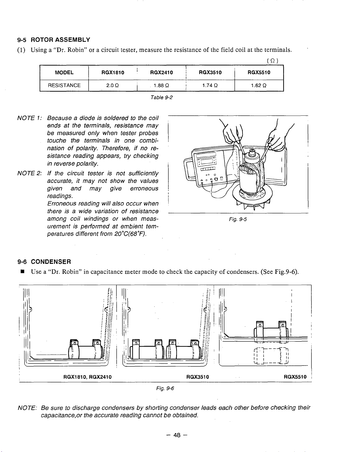
Using a "Dr. Robin" or a circuit tester, measure the resistance of the field coil at the terminals.
(1)
ASSEMBLY
NOTE
NOTE
MODEL
RESISTANCE
1:
Because a diode is soldered to the coil
ends at the terminals, resistance may
be measured
touche the terminals in one combination of polarity. Therefore, if no resistance reading appears, try checking
in reverse polarity.
2:
If the circuit tester is not sufficiently
accurate,
given and may give erroneous
readings.
Erroneous reading will also occur when
there is a wide variation of resistance
among coil windings or when measurement is performed at embient temperatures different from
I
I
RGXl810
2.0
R
only
when tester probes
it
may not show the values
20°C(68"F).
I
RGX2410
1.88
R
Table
9-2
1
j
i
!
!
!
j
!
i
I
RGX3510
1.74
R
i
Fig.
RGX5510
1.62
9-5
(0)
R
!
I
9-6
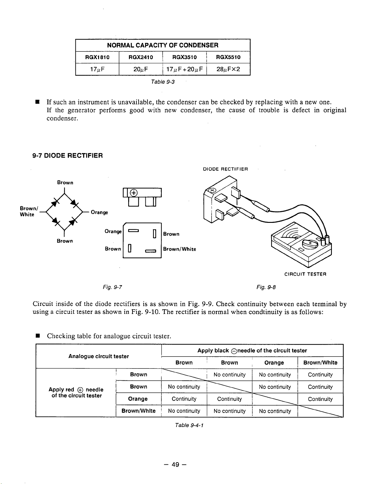
CONDENSER
Use
a "Dr. Robin" in capacitance meter mode to check the capacity of condensers. (See Fig.9-6).
i
RGXl810, RGX2410 RGX3510
Fig.
9-6
NOTE: Be sure to discharge condensers by shorting condenser leads each other before checking their
capacitance,or the accurate reading cannot be obtained.
RGX5510
I
I
i
-
40
-
Page 52
NORMAL CAPACITY
I
RGX1810
1
7,z F
W
If such an instrument is unavailable, the condenser can be checked by replacing with a new one.
If
the generator performs good with new condenser, the cause of trouble is defect in original
I
RGX2410
2OcF
OF
CONDENSER
I
I
RGX3510
i
17,zF+20#F I 28,zFX2
Table
9-3
I
RGX5510
I
condenser.
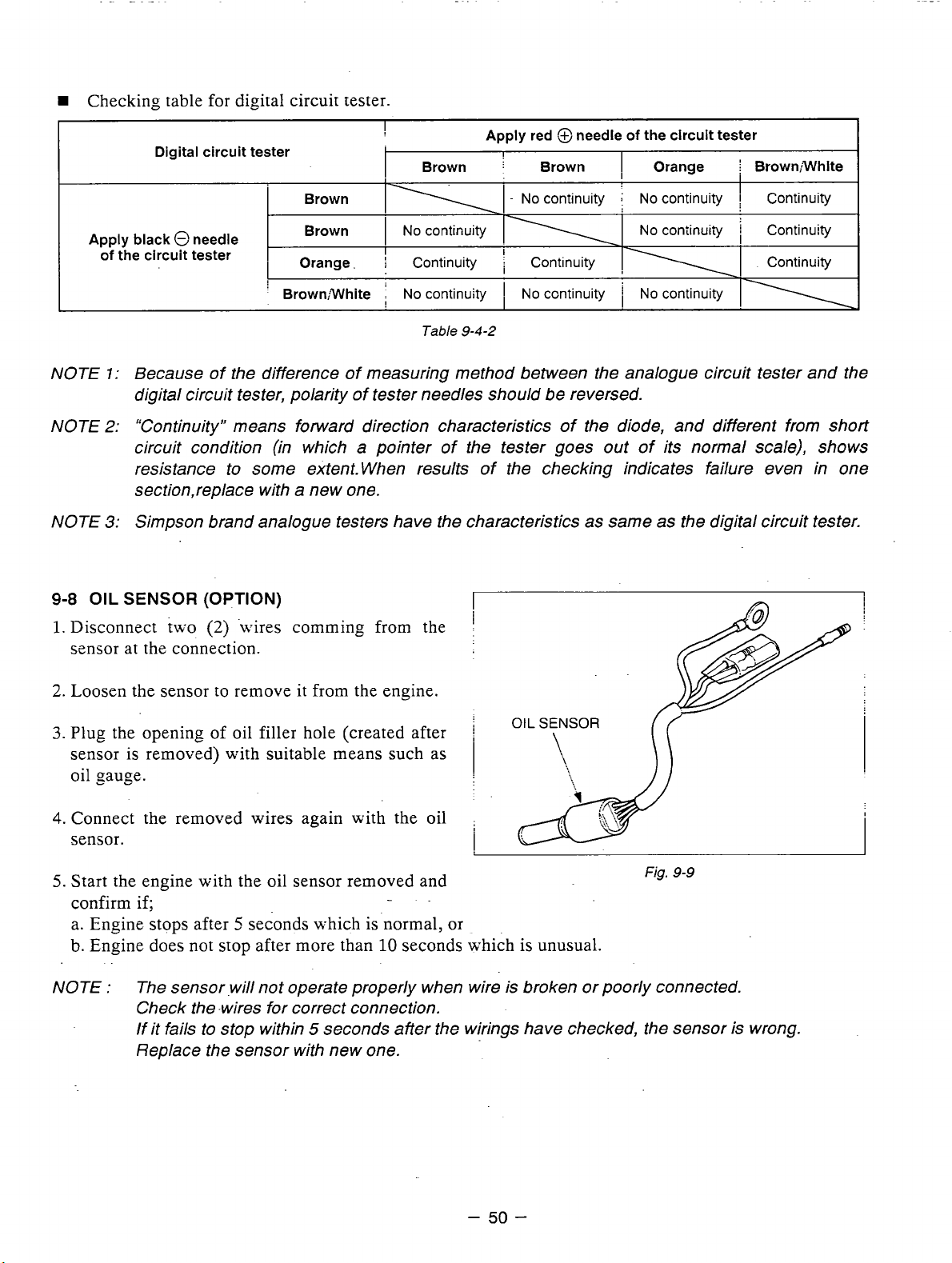
9-7
DIODE RECTIFIER
DIODE
RECTIFIER
Brown
Brown/
White
Brown
Orange
Fig.
Orange
Brown1
9-7
0
0
IBrown
-
I
Brown/White
Circuit inside of the diode rectifiers is as shown in Fig.
using a circuit tester
W
Checking table for analogue circuit tester.
Analogue circuit tester
Apply red @ needle
of
the circuit tester
as
shown in Fig.
!
:
I
I
1
Brown;White
Brown
Brown
Orange
9-10.
The rectifier is normal when condtinuity is as follows:
I
;
I
No
I
No
Brown
continuity
Continuity
continuity
9-9.
Check continuity between each terminal by
Apply black Oneedie
:
i
j
\I
'
Brown
NO
continuity
Continuity Continuity
No
continuity
.
I
I
j
CIRCUIT
Fig.
9-8
of
the circuit tester
Orange
NO
continuity
NO
continuity Continuity
No
continuity
TESTER
I
BrownWhite
;
cmtinuity
i
i
i\
i
Table
9-4-
1
-
49
-
Page 53
W
Checking table for digital circuit tester.
Digital circuit tester
Brown
Apply black 0 needle
of
the circuit tester
Brown
Orange.
’
Brown;White
!
Brown
11
I
NO
contir;uity
I
i
Continuity
I
No
continuity
Table
Apply red @needle
I
j
Brown
-
NO
continuity
!
i
Continuity
I
No
ccntinuity
9-4-2
of
the circuit tester
I
Orange Brown;White
i
NO
continuity
No
coniinuiiy Continuity
,
No
continuity
I
I
i
Ccntinuity
Continuity
NOTE
NOTE
1:
Because of the difference of measuring method between the analogue circuit tester and the
digital circuit tester, polarity
‘Continuity” means forward direction characteristics of the diode, and different from short
2:
circuit condition (in which
of
tester needles should be reversed.
a
pointer of the tester goes out of its normal scale), shows
resistance to some extent. When results of the checking indicates failure even in one
a
section,replace with
NOTE
9-8
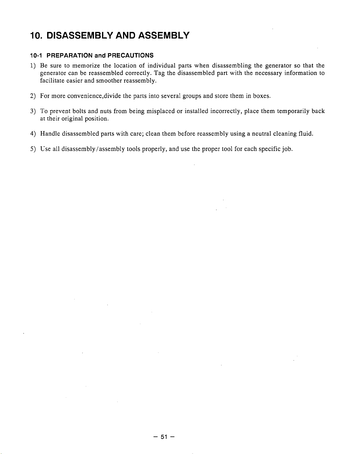
Disconnect tn-o
1.
Simpson brand analogue testers have the characteristics
3:
OIL
SENSOR (OPTION)
(2)
.\%-ires comming from the
new one.
sensor at the connection.
Loosen the sensor
2.
Plug the opening of oil filler hole (created after
3.
to
remove it from the engine.
sensor is removed) with suitable means such as
oil gauge.
Connect the removed wires again with the oil
4.
sensor.
as
same
I
as
the digital circuit tester.
I
Fig.
5.
Start the engine with the oil sensor removed and
9-9
confirm if;
5
a. Engine stops after
b. Engine does not stop after more than
seconds which is normal, or
10
seconds which is unusual.
NOTE : The sensor .will not operate properly when wire is broken or poorly connected.
Check the -wires for correct connection.
If it fails to stop within
5
seconds after the wirings have checked, the sensor is wrong.
Replace the sensor with new one.
-
50
-
Page 54
10.
DISASSEMBLY AND ASSEMBLY
10-1
PREPARATION
1)
Be sure to memorize the location of individual parts when disassembling the generator
v
generator can be reassembled correctly. Tag the disassembled part with the necessary information to
and
PRECAUTIONS
so
that the
facilitate easier and smoother reassembly.
2)
For more convenience,divide the parts into several groups and store them in boxes.
3)
To
prevent bolts and nuts from being misplaced or installed incorrectly, place them temporarily back
at their original position.
4) Handle disassembled parts with care; clean them before reassembly using a neutral cleaning fluid.
5)
Use
all disassembly/assembly tools properly, and use the proper tool for each specific job.
-
51
-
Page 55

10-2
DISASSEMBLY PROCEDURES
Step ;Part to remove
1.
Fuel Tank
I
(1)
Discharge fuel from the tank.
1. Shut the fuel strainer.
2.
i
Remove the strainer cup.
3. Put a vessel
strainer and open the fuel cock to
dischzrge fuel. (See Fig.
1.
Atrach [he straicer cap to tine srrainer
bo+.
Description
LO
receive fuel under the
10-1.)
Remarks
I
Use utmost care about
fire hazard.
Wipe off sprit fuel
thoroughly.
Do not lose the filter
SCieeG.
j
!
I
!
Tool
Fig.
10-1
i2j
Disconnect fuel hose from the strainer.
Loosen
strainer and
the strainer. (See Fig. 10-2.)
(3j Take off the four bolts and rubber (fuel
tank) and then remove the fuel tank.
(See Fig. 10-3.)
the hose clamp
pull
out the fuei hose from
on
top of the
//
1
I
j
!
i
-
Pliers
10
mm spanner or
box wench
t
I
..T\
\
Fig.
10-2
Fig.
10-3
-
52
-
Page 56
!
Step
-
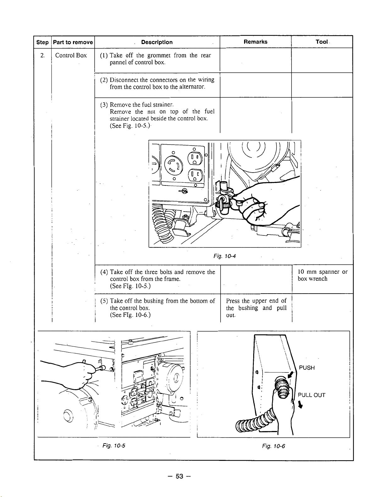
2.
Part to remove
Control
Box
I
(1)
Take off the grommet from the rear
.
Description
pannel of control box.
(2)
Disconnect the connectors
from the control box to the alternator.
(3)
Rerxove the fuel strainer.
Rerr.o.:e the
nut
on
top
strainer located beside the contro!
[See
Fig.
10-5.)-
on
the wiring
of
the fuel
box.
I
Remarks
i
Tool
-
L
(4)
Take off the three bolts and remove the
control box from the frame.
the control box.
FIg.
(See
10-6.)
Fig.
10-4
I
the bushing and pull
I
out.
I
10
mm spanner or
!
box wrench
-
Fig.
10-5
I
Fig.
10-6
-
53
-
Page 57
step
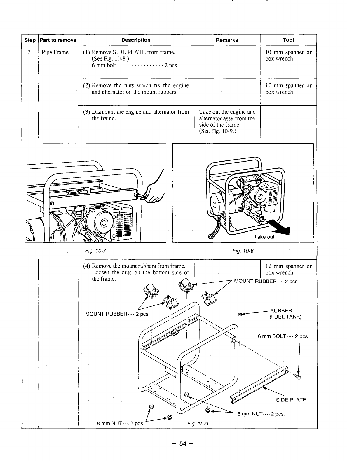
3.
Part
to remove
I
Pipe Frame
I
I
(1)
1
I
Remove
(See Fig
6
mm
bolt
Description
SIDE
PLATE from frame.
10-8.)
. . . . . . . . . . . . . . . .
2
PC-.
Remarks
10
box
Tool
mm
spanner or
wrench
(2)
Remove the nuts Lvhich fix [he engine
1
and alternator
1
(3)
Dismount the engine and alternator
!
the frame.
on
the mount rubbers.
I
from
i
1
1
I
Take out the engine
i
alternator assy from the
side
of
the frame.
(See Fig.
lo-9.j
I
and
I
1
I
!
I
i
Fig.
10-7
(4j
Remove [he mount rubbers from frame.
Loosen
the frame.
MOUNT RUBBER...,
i
I
!
I
I
I
I
i
i
8
rnm
the
nuts
NUT....2
on
the bottom side of
pcs.
Fig.
'
I
I
10-9
Fig.
10-8
I
12
mm spanner
box wench
I
MOUNT RUBBER.... 2 pcs.
6
rnrn
BOLT.... 2 pcs.
8
mm
NUT.... 2 pcs.
or
-
54
-
Page 58

Step
4.
I
I
Part to remove
I
Rear Cover
I
!
1
!
il
j
Remove
I
.
.
rear cover to the front cover.
-1
69
bolt-.
Description
the
four bolts Lvhich fxen
. . . . . . . .
I
!
(2)
Rmove the rear cover
i
legs
of
rear cover Lvith a plastic hammer
co
i
loosen.
. . . .
. . .
by
4
pes.
hitting
on
i
the
the
Remarks
i
Do
not give 2 strong hit 1 Plastic hammer
I
on
the legs.
'
!
I
i
I
I
I
12
box
i
Tool
mm. spanner
wench
or
Startor
Fig.
(1)
Remove
10-10
the
stator cover.
Fig.
10-1
7
I
1
STATOR
i
!
I!
i
STAT
COVER
:! !
;
I
L
I
Fig.
10-12
-
55
-
Page 59

Part to remove
Step
5.
Stator
I
i
j
Description
Remarks
Tool
6.
I
!
CLAMP
(1
j
Take
off
the through bolt.
Apply
a
box
wench
on
through bolt. Hit the wrench hzndle with
a hammer cocnter-clockwise to
the head
loosen.
Fig.
of
70-73
i
j
I
!
STATOR
COVER
Box
wrench
Plastic hammer
-
(2)
Put the engine
on
the
working
Fig.
10-14
table recoil starter side
-
56
-
down.
!
I
Page 60

Step
6.
Part
i
Rotor
i
I
to remove Description
(3j
Use a bolt and oil as a
I
out rotor
:
1. Pour engine oil into the center hole of
i
!
I
:
2. Prepare a bolt with the following
i
i
3.
I
in
the following procedures
rotor shaft.
Fill Lvith oil to the shaft end.
(See Fig. 10-15.)
thread size:
RGX1810, 2410,3510. . h.IlOXP1.25
RGX5510.
Apply a few turns of seal tape around
the tip of the bolt.
(SeeFig.
.
.
.-.
10-16.)
tool
. . . . . .
for pulling
M12XP1.50
i
!
!
Remarks
Tool
j
:
1
i
1
I
Fig.
10-15
4.
Screw the bolt into the thread of
rotor shaft.
5. Torque the bolt using a socket wrench
until the rotor comes off
*
The hydraulic pressure inside the rotor
shaft takes apart the rotor from the
engine shaft.
(4)
U;ipe off oii thoroughly from rotor shaft
and engine
PTO
shaft.
loose.
the
j
I
i
i
i
Fig.
10-16
Socket wrench
I
Fig.
10-1
7
-
57
-
Page 61

step
I
Part
to remove
(1)
Remo1.e
Loosen
front
30
cover.
bolt.
Description
rhe
front
the
four
. . . . .
cover.
bois
and
. . . . . . . . . .
remove
4
pes.
the
12
mm
\vrench
Tool
Socket
Remarks
I
i
I
Fig.
10-18
I
I
-
58
-
Page 62

10-3 ASSEMBLY PROCEDURES
10-3-1 FRONT COVER
Attach the front cover to the engine main bearing cover.
Match the faucet joint and tighten the bolts.
M8
X
18mm bolt.
“8
spring washer
. . .
.
. . . .
.
.4
4
pcs.
pcs.
120 - 140 kgocrn
\
8.7- 10.1
ft*lb
‘1
10-3-2
(1)
(2) Mount the rotor to the engine shaft.
ROTOR
Wipe off oil, grease and dust from the tapered portion of
engine shaft and matching tapered hole
of
rotor shaft.
Tighten the through bolt.
Apply a wrench on the through bolt and hit wrench handle
to
clockwise with a hammer
If
an impact wrench is available, use it.
Tightening torque
:
tighten.
FRONT
COVER
I
I
RGX
1810,2410
RGX
351
0,551
Tightening torque
0
I
11.3-13.2
115-135 kg-cm
j
!tt
8.7 - 10.8
22.6 - 24.5
.!
230-250 kgocrn
i
’:\.
16.6
-
19.5
Nm
ft4b
N-rn
ft4b
\!
I
,i‘
~‘:
I
j
I
I
BEARING
-
59
-
Page 63

10-3-3 STATOR
(1)
Put the stator in the rear cover setting the four
-
grooves
of
(2)
Attach.the stator cover around the stator.
on
the side of stator with thread holes
the rear cover;
:
'
i
!
!
!
STATOR
I
I
""""
.T-
I'
I
:'
I
Fig.
10-20
-.
.
-
I
I
COVER
10-3-4 REAR
(1)
Put the rear cover with stator over the rotor. Tap on the rear cover evenly with a plastic hammer to
COVER
press the rotor bearing into the rear cover.
Fix
the rear cover to the adaptor with four
bolts, spring washers, and washers.
M6
x
M6
M6
I
Tightening torque
i
I
'z.~
25 mm bolt ..............
spring washer
LVasher
.....................
.............
I
4.9 - 5.9
50
-60
3.6 -4.3
Nm
kg-crn
ft*lb
',!:
j
4
4
4
pcs.
pcs.
pcs.
Fig.
10-21
-
60
-
Page 64

(3)
Attach the bushing over the lead wire drawn
out from the rear cover.
of
Press the smaller -end
window of
the rear cover.
the bushing into the
i
I
j
Fig.
10-22
10-3-5
(1)
NOTE : The mount rubbers are selected to reduce vibration most effectively by model and its
FRAME
Attach the mount rubbers to the frame.
Insert the setting tongue of mount rubber into
the hole
the bottom of the frame.
h18
on
the frame and tighten the
nut
flan,
frequency.
Be sure to use the correct mount rubber for your generator.
Although mount rubbers have the same appearance, their characteristics are different.
......................
4
nut
pcs.
from
r-
Fig.
10-23
FRAME
UPPER
(2)
Attach the
frame base plate using a
5
Q
terminal of the grounding wires (greeniyellow)
5
mm brass
s-
Lrew.
-
61
to
the-unpainted thread hole
-
of
the
Page 65
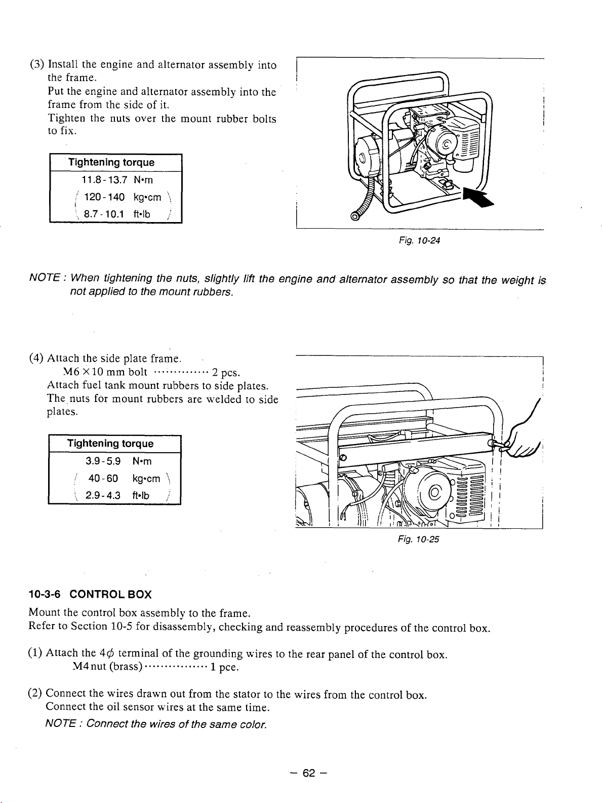
Install the engine and alternator assembly into
the frame.
Put the engine and alternator assembly into the
frame from the side of it.
Tighten the nuts over the mount rubber bolts
to
fix.
Tightening torque
1 1.8
-
13.7
Nom
:.
120
-
140
’,
8.7 - 10.1
kg*cm
ft*lb
.i
;
Fig.
10-24
NOTE
:
When tightening the nuts, slightly lift the engine and alternator assembly
not applied to the mount rubbers.
(3)
Attach the side plate frame.
M6
x
10
mm bolt
..............
2
pcs.
Attach fuel tank mount rubbers to side plates.
The.nuts for mount rubbers are welded to side
plates.
3.9
-
5.9
Nom
....
2.9-4.3
ft4b
:
Fig.
10-25
so
that the weight is
10-3-6
CONTROL
BOX
Mount the control box assembly to the frame.
10-5
Refer to Section
(2)
Connect the wires drawn out from the stator to the wires from the control
for disassembly, checking and reassembly procedures
Connect the oil sensor u-ires at the same time.
NOTE
:
Connect the wires
of
the same color.
-
62
-
of
the control box.
box.
Page 66

(3)
Press the upper end of the bushing into the
bottom window of the control box.
Attach the grommet for the oil sensor wires to
the rear panel
(4)
Mount the control box to the frame.
346
X12
I
Tightening torque
of the control box.
mm flange bolt
..........
I
3
pcs
.
Fig.
."
10-26
I'
5.9
60
Nom
kg-cm
ftolb
':!
/
3.9
-
/
40-
!,
2.9-4.3
(5)
Fasten the one earth cable with
drawn out from the control box to the rear
cover leg.
M8
nut
...........................
',
5.8-7.2
fblb
Fasten the other earth cable with
5
0
TERMINAL
(FRAME!
86
terminal
Fig.
70-27
1
pce.
5@
terminal to the unpainted bolt hole on the frame. (See Fig.10-36.)
6$
TERMINAL
(CONTROL
BOX)-
8
d
TERMINAL
(REAR COVER)
I
I
Fig.
10-28
-
63
-
Page 67
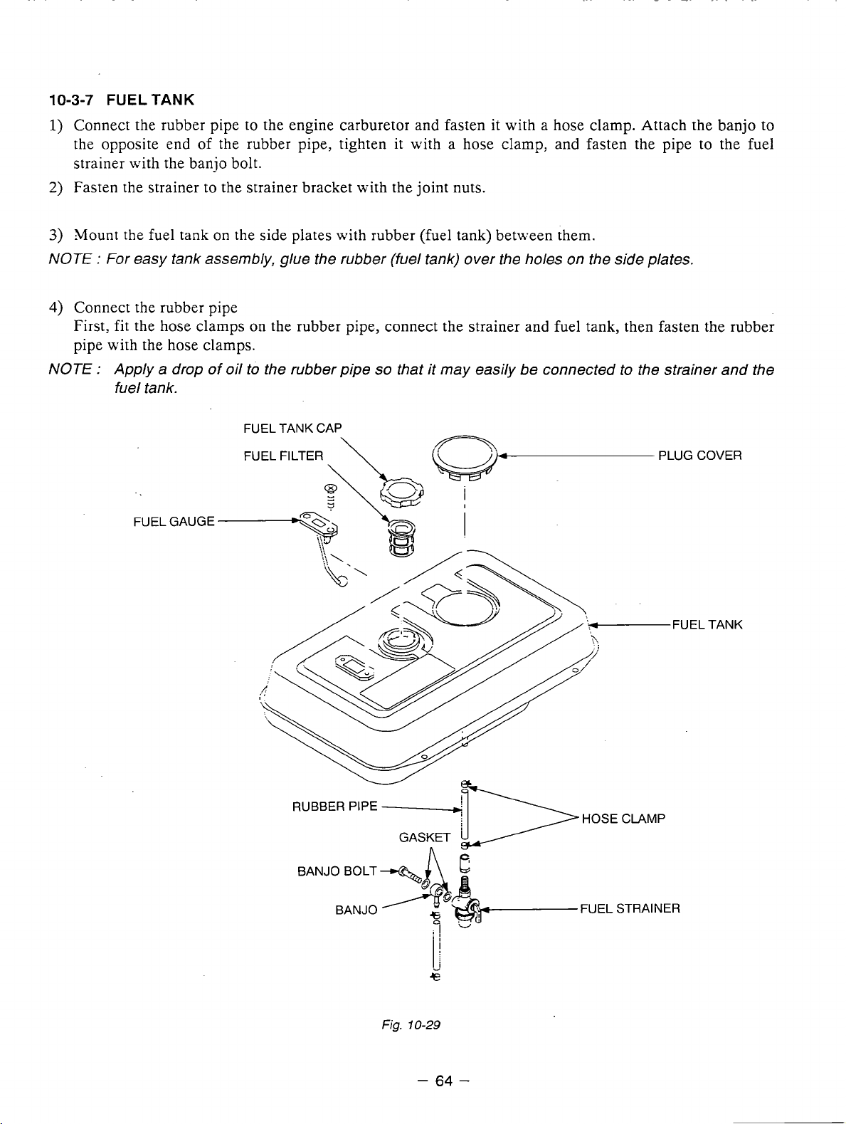
10-3-7
1)
FUEL
TANK
Connect the rubber pipe to the engine carburetor and fasten
the opposite end
of
the rubber pipe, tighten it with a hose clamp, and fasten the pipe to the fuel
it
with a hose clamp. Attach the banjo to
strainer with the banjo bolt.
2)
Fasten the strainer to the strainer bracket with the joint nuts.
3)
Mount
the
fuel tank
on
the side plates with rubber (fuel tank) between them.
NOTE : For easy tank assembly, glue the rubber (fuel tank) over the holes on the side plates.
4)
Connect the rubber pipe
fit
First,
the hose clamps
on
the rubber pipe, connect the strainer and fuel tank, then fasten the rubber
pipe with the hose clamps.
NOTE : Apply a drop of oil
to
the rubber pipe
so
that it may easily
be
connected
to
the strainer and the
fuel tank.
FUEL GAUGE
.FUEL TANK
RUBBER PIPE
GASKET
Fig.
10-29
-
64
-
Page 68
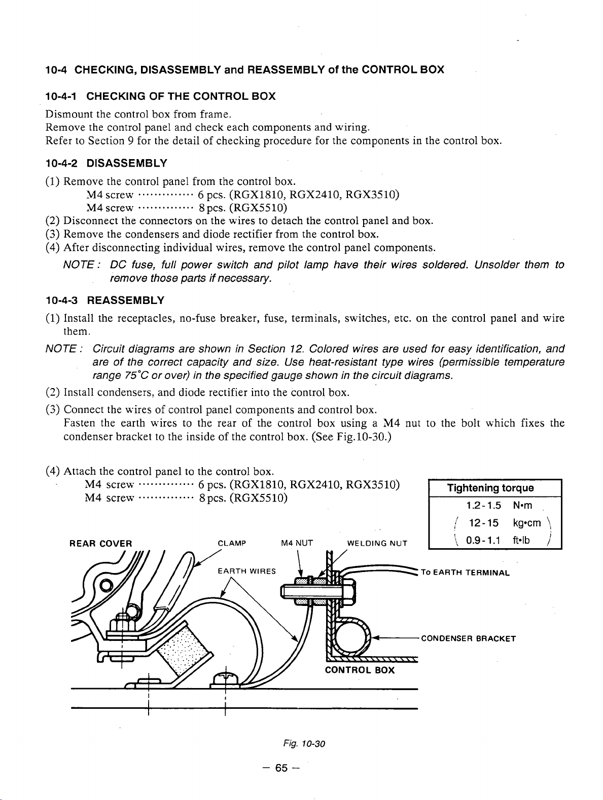
10-4 CHECKING, DISASSEMBLY
OF
10-4-1 CHECKING
THE CONTROL BOX
and
REASSEMBLY
of
the
CONTROL BOX
Dismount the control box from frame.
Remove the control panel and check each components and wiring.
Refer to Section
10-4-2 DISASSEMBLY
(1)
Remove the control panel from the control box.
M4 screw
(2)
Disconnect the connectors on the wires to detach the control panel and box.
(3)
Remove the condensers and diode rectifier from the control box.
(4)
After disconnecting individual wires, remove the control panel components.
9
screw
for the detail of checking procedure for the components in the control box.
..............
..............
6
pcs. (RGX1810, RGX2410, RGX3510)
8
pcs. (RGX5510)
NOTE : DC fuse, full power switch and pilot lamp have their wires soldered. Unsolder them to
remove those parts if necessary.
10-4-3 REASSEMBLY
(1)
Install the receptacles, no-fuse breaker, fuse, terminals, switches, etc. on the control panel and wire
them.
NOTE : Circuit diagrams are shown in Section
12.
Colored wires are used for easy identification, and
are of the correct capacity and size. Use heat-resistant type wires (permissible temperature
range
(3)
Install condensers, and diode rectifier into the control box.
(3)
Connect the wires
75°C
or over) in the specified gauge shown in the circuit diagrams.
of
control panel components and control box.
Fasten the earth wires to the rear of the control box using a M4 nut to the bolt which fixes the
condenser bracket to the inside of the control box. (See Fig.10-30.)
Attach the control panel to the control box.
“4
M4 scre\v
REAR
ScreLV
COVER
..............
..............
6
pcs. (RGX1810, RGX2410, RGX3510)
8
pcs. (RGX5510)
CLAMP
EARTH
WIRES
M4
NUT
WELDING
1.2 - 1.5
NUT
To EARTH TERMINAL
,CONDENSER BRACKET
Nom
I
I
I
I
I
I
Fig.
10-30
-
65
-
Page 69
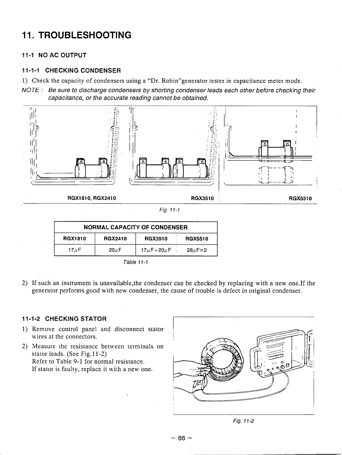
11.
TROUBLESHOOTING
11-1 NO AC OUTPUT
11 -1 -1 CHECKING CONDENSER
1)
Check the capacity
NOTE
:
Be sure to discharge condensers by shorting condenser leads each other before checking their
of
condensers using a ”Dr. R0bin”generator tester in capacitance meter mode.
capacitance, or the accurate reading cannot be obtained.
RGX1810, RGX2410 RGX3510
Fig.
11-1
I
RGXl810 RGX2410 RGX3510 RGX5510
2)
If such an instrument is unavailable,the condenser can be checked by replacing with a new one.If the
v
generator performs good with new condenser: the cause of trouble is defect in original condenser.
11-1-2 CHECKING STATOR
1)
Remove control panel and disconnect stator
17yF
NORMAL CAPACITY
i
I
1
20yF
Tzble
OF
CONDENSER
17,cF+20yF
11-1
:
28,zFX2
:
I
RGX5510
wires at the connectors.
2)
Measure the resistance between terminals on
stator leads. (See Fig.11-2)
9-1
Refer to Table
If
stator is faulty, replace it with a new one.
for normal resistance.
Fig.
1
1-2
-
66
-
Page 70
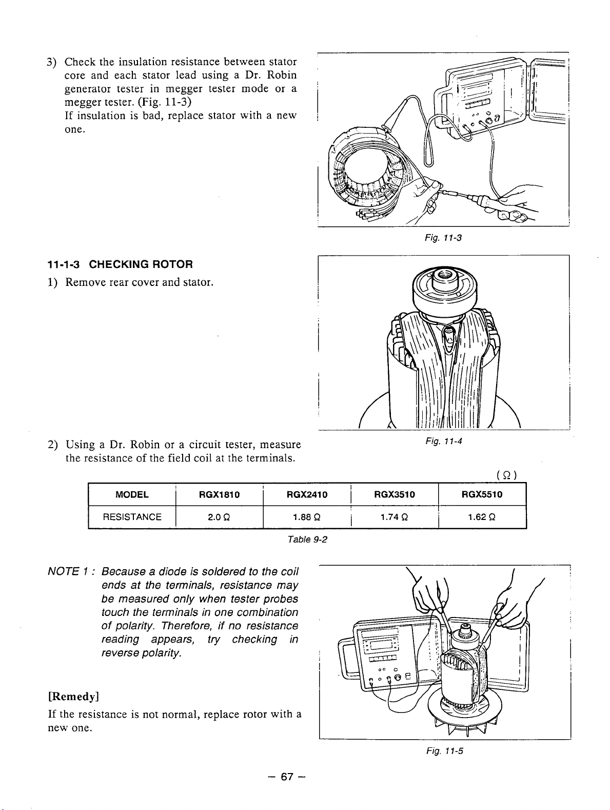
3)
Check the insulation resistance between stator
core and each stator lead using a Dr. Robin
generator tester in megger tester mode or a
megger tester. (Fig.
If
insulation
one.
11
-1-3
CHECKING
1)
Remove rear cover and stator.
is
11-3)
bad, replace stator with a new
ROTOR
'
I
j
I
I
i
i
Fig.
1
1-3
Using a Dr. Robin or a circuit tester, measure
the resistance of the field coil at the terminals.
MODEL
I
RESISTANCE
NOTE
[Remedy]
If
new one.
1
:
Because a diode is soldered to the coil
ends at the terminals, resistance may
be measured only when tester probes
touch the terminals in one combination
of polarity. Therefore,
reading appears, try checking in
reverse polarity.
the resistance is not normal, replace rotor with a
1
RGXl810 RGX2410
I
2.0
R
if
no resistance
1.88
Table
!
R
9-2
I
1
1
RGX3510
'.74R
Fig.
!
I
11-5
..
RGX5510
1.62
R
-
67
-
Page 71
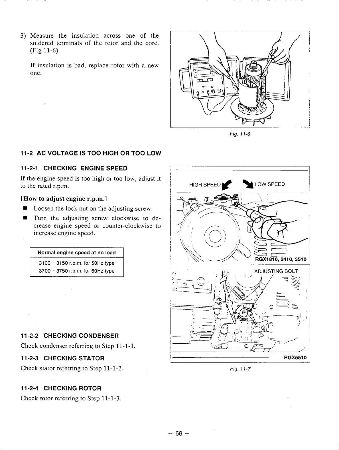
3)
Measure the insulation across one of the
soldered terminals
11-6)
(Fig.
of the rotor and the core.
If insulation is bad, replace rotor with a new
one.
11-2 AC VOLTGE IS TOO HIGH OR TOO LOW
11-2-1 CHECKING ENGINE SPEED
If
the engine speed is too high or too low., adjust
to the rated r.p.m.
it
HIGH
SPEED
Fig.
rf
11-6
Q
LOW
SPEED
[How
to
adjust
w
Loosen
w
Turn the adjusting screw clockwise to de-
engine
the lock nut
r.p.m.1
on
the adjusting screw.
crease engine speed or counter-clockwise to
increase engine speed.
Normal
31
3700 - 3750 r.p.m. for
11-2-2 CHECKING CONDENSER
Check condenser referring to Step
11-2-3 CHECKING STATOR
engine speed at no load
00
-
31
50
r.p.m.
for
50HZ
60Hz
~~~~~ ~~~
?ype
type
11-1-1.
i
i
i
i
I
I
..
. .
..
;:
RGX5510
Check stator referring to Step
11
-2-4
CHECKING ROTOR
Check rotor referring to Step
11-1-2.
11-1-3.
Fig.
11-7
-
68
-
Page 72
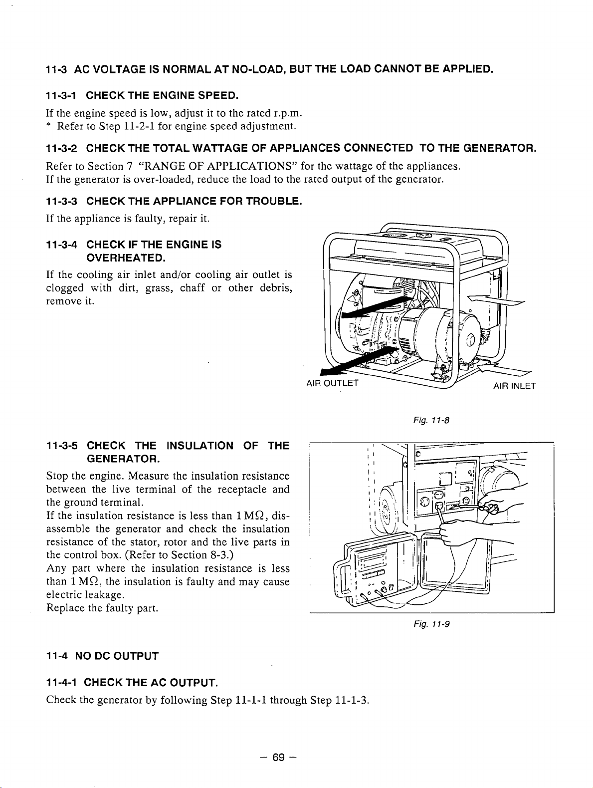
11-3 AC VOLTAGE
11-3-1 CHECK THE ENGINE SPEED.
IS
NORMAL AT NO-LOAD, BUT THE LOAD CANNOT BE APPLIED.
If the engine speed is low, adjust it to the rated r.p.m.
*
Refer to Step 11-2-1 for engine speed adjustment.
11-3-2 CHECK THE TOTAL WATTAGE
Refer
to
Section 7 “RANGE
OF
APPLICATIONS” for the wattage of the appliances.
OF
APPLIANCES CONNECTED TO THE GENERATOR.
If the generator is over-loaded, reduce the load to the rated output of the generator.
11-3-3 CHECK THE APPLIANCE
FOR
TROUBLE.
If the appliance is faulty, repair it.
11-3-4 CHECK
OVERHEATED.
IF
THE ENGINE
IS
If the cooling air inlet andlor cooling air outlet is
clogged with dirt, grass, chaff or other debris,
remove it.
Fig.
11-8
11-3-5 CHECK THE INSULATION
GENERATOR.
OF
THE
Stop the engine. Measure the insulation resistance
between the live terminal
of
the receptacle and
the ground terminal.
1
MO,
If the insulation resistance is less than
disassemble the generator and check the insulation
resistance of the stator, rotor and the live parts in
the control box. (Refer to Section
Any
part where the insulation resistance is less
1
MQ:
than
the insulation is faulty and may cause
8-3.)
electric leakage.
Replace the faulty part.
11 -4 NO DC OUTPUT
11-4-1 CHECK THE AC OUTPUT.
Check
the
generator by following Step
11-1-1
through Step 11-1-3.
I
:
\-q
+===========
-
69
-
Page 73
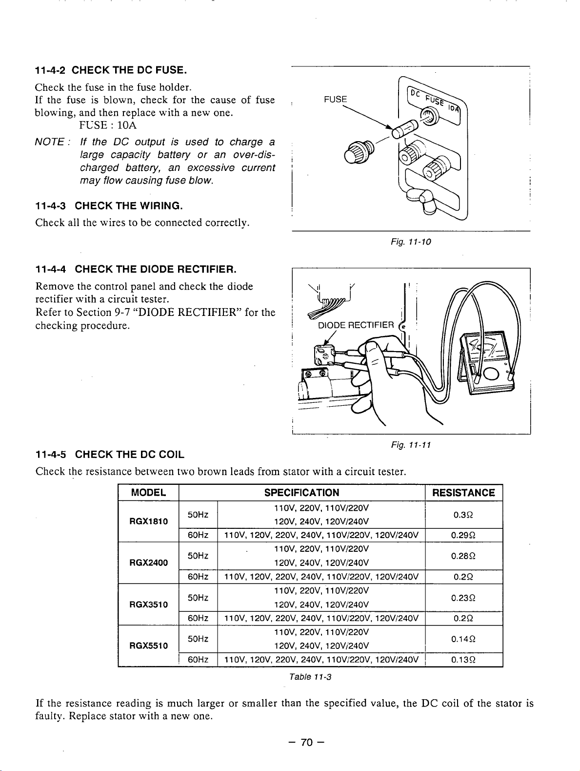
11 -4-2 CHECK THE DC FUSE.
Check the fuse in the fuse holder.
If the fuse
blowing, and then replace with a new one.
is
blown, check for the cause of fuse
FC-SE
:
10A
NOTE:
11-4-3 CHECK THE WIRING.
Check all the wires to be connected correctly.
11 -4-4 CHECK THE DIODE RECTIFIER.
Remove the control panel and check the diode
rectifier with a circuit tester.
Refer
checking procedure.
If the
large capacity battery or an over-discharged battery, an excessive current
may flow causing fuse blow.
to
Section
DC
output is used to charge a
9-7
“DIODE
RECTIFIER” for the
Fig.
11-70
Fig.
11-11
11-4-5 CHECK THE
Check the resistance between two brown leads from stator with a circuit tester.
If the resistance reading is much larger or smaller than the specified value, the DC coil of the stator is
faulty. Replace stator with a new one.
DC
COIL
MODEL
RGXl810 120V. 240V, 12OVi24OV
RGX2400
I
I
RGX5510
I
50HZ
I
60HZ I 11 OV. 120V. 220V. 240V. 11 OVi22OV. 12OVi24OV
50Hz
I
60Hz I 11 OV, 120V, 220V, 240V, 11 OV/22OV, 120V!240V
I I
60Hz
I
11
OV, 120V, 220V, 240V, 11 OV/22OV, 120Vi240V
I
50Hz
I
i
I
I
60Hz I 11 OVt 120V, 220V, 240V, 1 1 OV;22OV, 120V;240V
SPECIFICATION
1 1
ov,
220v, 1 1 OVl22OV
1 1
ov,
220v, 1 1 OV!‘220V
120V, 240V, 120Vj240V
1 1 ov, 220v, 1 1 OV/220V
120v. 210v. 120v;240v
11 ov, 220v, 11 ovi’220v
120V. 240V. 120Vi240V
Tabie
1
1-3
I
RESISTANCE
I
0.30
i
I
I
0.2952
0.280
I
0.2R
0.230
I
I
0.2R
I
0.140
I
!
0.1 30
I
I
I
-
70
-
Page 74

11-5
IDLE
CONTROL
11
-5-1
ENGINE- SPEED
(1) Inspect the solenoid bracket.
Check the bend angle
If the bracket is distorted, correct the angle
with proper tool.
(Option for 60Hz
IS
NOT INCREASED WHEN A LOAD
of
solenoid bracket. i
only)
IS
APPLIED
'
1
I
SOLENOID
SOLENOID BRACKET
Fig.
11-12
(2)
Check the wattage of load appied to the generator.
If
the generator is loaded over the rated wattage, the engine speed can not be increased.
Most induction loads such .as electric motor or electric tools or welding machine require three to five
times large wattage of their ratings at starting.
This starting wattage must not exceed the rated output of the generator.
(3)
Check the slow set r.p.m.
by
The normal idling speed
CONTROL is as follows
:
the IDLE
..
RGX5510
!
RGX2410, 3510
RGX5j10
Adjust the idling speed monitoring the voltmeter
85
volt.
Turn the adjusting screw to adjust the
speed.
..............
so
that it indicates between
*.**-*
3150 - 3200 r.p.m.
2700
-
2800
r.p.m.
75
volt and
-
slow
71
-
Page 75

(4)
Check the wiring through ZCT
CONTROL UNIT BOARD.
0
Single Voltage Type
Make sure that an output wire from main coil
passing through the ZCT
CONTROL UNIT.
0
Dual Voltage Type
Check that two output wires (black wire and red
wire) from main coils are passing through the
ZCT on the IDLE CONTROL UNIT in the
same direction.
(5)
Checking the IDLE CONTROL UXIT
Check the resistance between six leads
on
on
the IDLE
the IDLE
of
is
I
DL€
CONTROL UNIT
3
IDLE CONTROL
UNIT
Fig.
11-14
with circuit tester.
I
Tester
LIGHT BLUE
LIGHT BLUE
NOTE : Take
If the measurement differs largely from mormal value, the IDLE CONTROL UNIT is defective.
Replace with a new one.
..
Polaritv
(FUSE)
5
10%
\.
IDLE
CONTROL UNIT
tolerance on above resistance value.
.
20-50kQ
Fig.
11-15
I
I
2-16kQ
Tzble
11
-4
I
.
:
-
72
-
Page 76

11-5-2
ENGINE SPEED
IS
NOT REDUCED
WHEN
LOAD
IS
OFF.
(1)
Check the distortion of the SOLENOID BRACKET as shown in step
11-5-1-(1).
(2)
Check the
FUSE
on wiring of IDLE CONTROL
UNIT.
Remove the. control panel from control box.
Check the FUSE in the fuse holder
of
IDLE COKTROL UNIT.
If fuse
is
blown, replace with a new one. (FUSE : 0.2A)
FUSE HOLDER
Fig.
11-16
(3)
Check the wiring of SOLENOID.
Check two leads from SOLENOID are securely connected.
(4)
Check the wiring of IDLE COKTROL USIT.
Check all leads from IDLE COXTROL UXIT are securely and correctly connected.
(5)
Checking the SOLENOID.
SOLENOID
Measure the resistance between two leads from
SOLENOID.
If the resistance is larger or smaller than this
range, SOLENOID is defective,
Replace with a new one.
Fig.
11-17
-
73
-
Page 77

12.
WIRING DIAGRAM
1. RGX1810, RGX2410 (llOV, 120V)
I
1
EhlC
I I
I
NFB
GENERATOR
CONTROLBOX
"I
I"
"I
1
'-3
1
YELLOW
"I
I
"
"
I
DC
OUTPUT
:
Available as option
DC
OUT
2. RGX1810, RGX2410 (220V, 240v)
GENERATOR
CONTROL BOX
L
"I
r
"
"
iii
II
NFB
AK
n
I
I,
GREENBELLOW
YELLOW
P
I
E
YELLOW
BROWN
DC
OUT
BROWN
I-
BROWN/'WHITE
--
DC
OUTPUT
:
Available as
option
-
74
-
Page 78

3.
RGXl810, RGX2410 (1 1 OV/22OV) (1 20V/240V)
GENERATOR
7°F
CONTROL
1"
BOX
DC
OUTPUT
:
Available as option
4. RGX3510 (1 lOV, 120V)
GENERATOR
"1
CONTROL
I"
..
BOX
"
DC
OUT
"
DC
OUTPUT
"
:
Available
as
option
-
75
-
Page 79

5.
RGX3510 (220V, 240V)
6.
RGX3510 (1 1 OV/22OV) (120V/240V)
GENERATOR CONTROLBOX
"I
I
I
I"
II
NFB
DC
OUTPUT : Available as option
DC
OUT
-
E
DC
OUTPUT : Available as option
-
76
-
Page 80
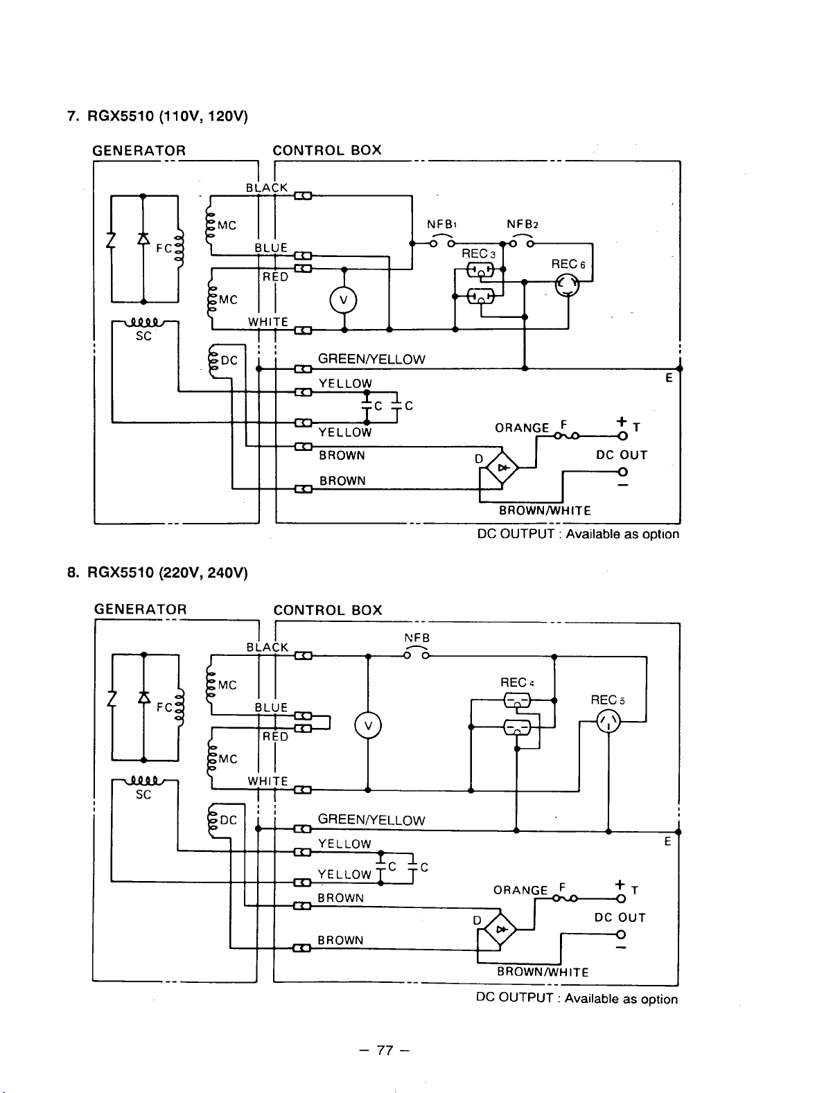
7.
RGX5510 (1 1 OV, 120V)
GENERATOR CONTROL
"1
I"
AK
BOX
DC
OUTPUT-:
"
Available
as
I
option
8.
RGX5510 (220V, 240V)
GENERATOR CONTROL
BOX
"
"
-
77
-
Page 81

9.
RGX5510
(1
1 OV/220V) (1 20V/240V)
GENERATOR CONTROLBOX
"1
I
I
YELLOW
YELLOW
lc
BROWN
"1
I
"
NFBl
"
ORAN
BROWN/WHITE
DC
OUTPUT
"
+T
DC OUT
0
-
"
:
Available as option
-
78
-
Page 82
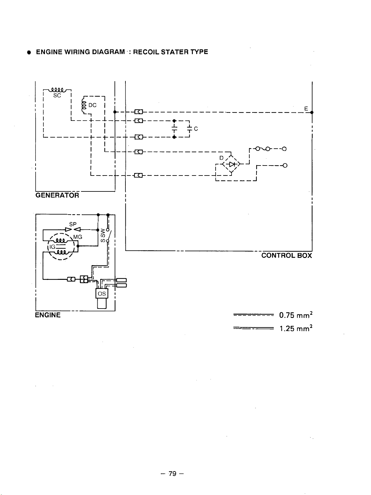
ENGINE WIRING DIAGRAM
.:
RECOIL STATER TYPE
"""_
rm-4
I
J
r---
I
_J
-0
ENGINE
"
-
79
-
Page 83
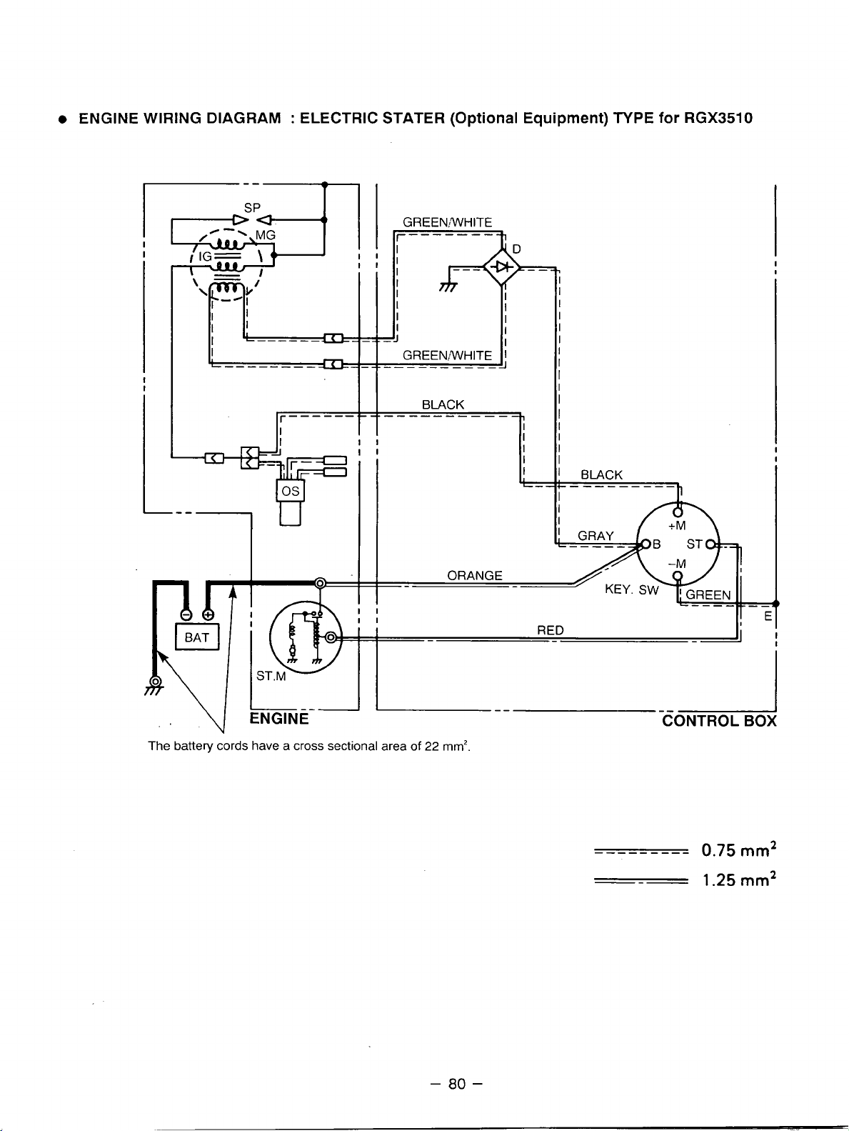
0
ENGINE WIRING DIAGRAM : ELECTRIC STATER (Optional Equipment)
TYPE
for
RGX3510
""7
I
Page 84
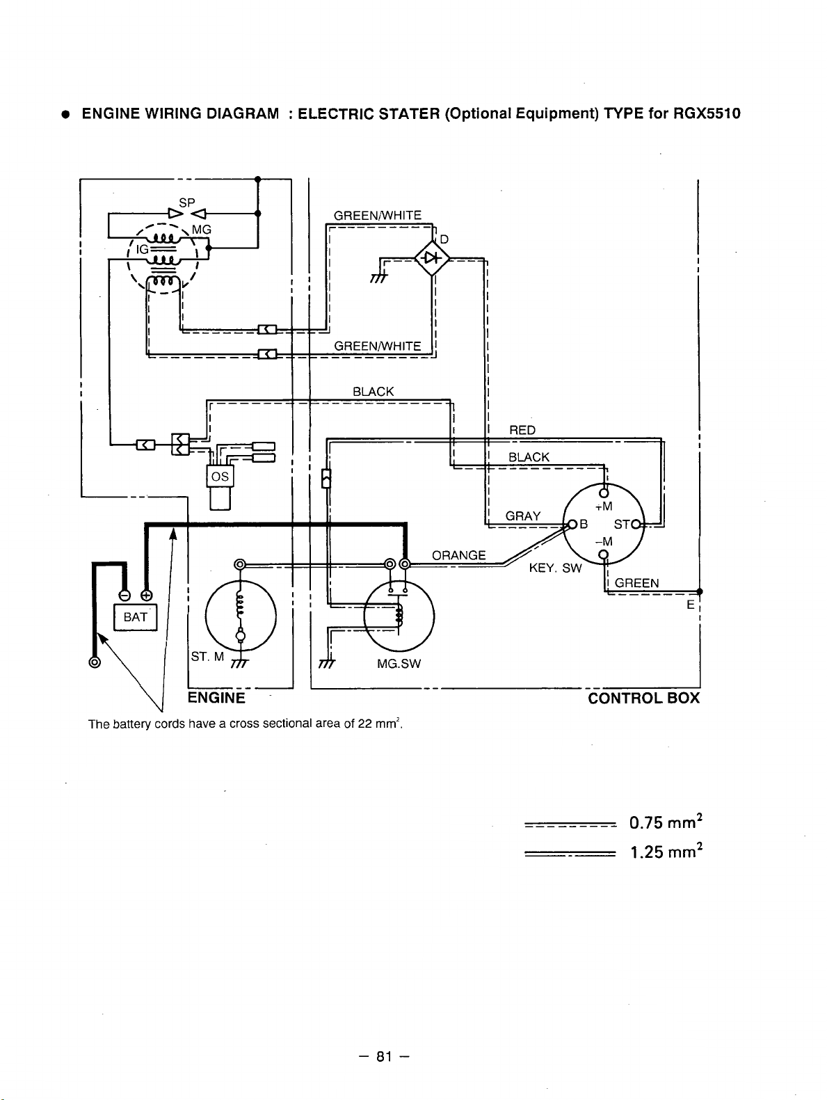
0
ENGINE WIRING DIAGRAM : ELECTRIC STATER
GREENiWHITE
Ir--------"h
I
(Optional
Equipment) TYPE
for
RGX5510
The battery cords have a cross sectional area
of
22
-
mm'.
81
""""
"-
-
0.75
1.25
mm2
mm2
-
Page 85
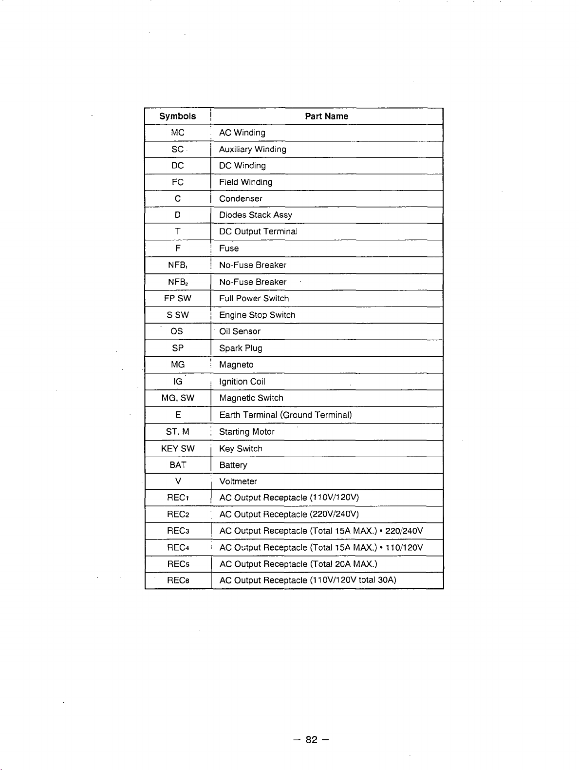
Symbols
M
c
SC
.
I
AC Winding
1
Auxiliary Winding
Part
Name
DC
FC
C
D
T
F
NFB,
NFB,
FP SW
S
SW
os
M G
IG
'
MG. SW Magnetic Swiich
E
ST.
M
DC Winding
Field Winding
I
Condenser
Diodes Stack Assy
DC Outpgt Terminal
\
Fuse
j
No-Fuse Breaker
1
No-Fuse Breaker
I
Fdll
Power Switch
I
i
Engine Stop Switcn
Oil Sensor
Spark Plug SP
j
Magneto
j
Ignition Coil
Earth Terminal (Ground Terminal)
Starting Motor
KEY SW
BAT
V
RECl
RECz
REC3 AC Output Receptacle (Total 15A
REC4 AC 0s:put Receptacle (Total 15A
RECs
RECe
Key Switch
Battery
Voltmeter
(1
AC OGipUt Receptacle
,
AC Output Receptacle (22OV/240V)
AC Output Receptacle (Total 20A
AC Output Receptacle
10V320V)
(1
1
OV/120V total 30A)
MAX.)
MAX.)
MAX.)
220;240V
11
0:120V
-
82
-
Page 86

I
ISSUE EMD-GS1001
I
@FUJI
HEAVY
INDUSTRIES LTD.
 Loading...