

Page 1
SERVICE
MANUAL-
Models
RGV2800, RGV4100,
RGV6100
Generators
PUB-GSI 277
Rev. 4/99
Page 2
.
CONTENTS
"
.
Section
Title
Page
1
.
SPECIFICATIONS
.......................................................................................................
1
2 . PERFOMANCE CURVES
...........................................................................................
3
3
.
FEATURES
..................................................................................................................
5
3-1 BRUSHLESS ALTERNATOR
................................................................................
5
3-2 CONDENSER TYPE VOLTAGE REGULATOR
....................................................
5
3-3
OIL
SENSOR
........................................................................................................
5
3-4 QUIET OPERATION
.............................................................................................
5
3-5 NO RADIO NOISE
................................................................................................
5
3-6 LARGE FUELTANK
..............................................................................................
5
3-7 RUGGED TUBULAR FRAME
...............................................................................
5
3-8 COMPACT AND LIGHT WEIGHT
.........................................................................
5
3-9 MINIMAL MAINTENANCE
....................................................................................
6
3-10 LONG-LIFE DURABILITY
...................................................................................
6
4
.
GENERAL DESCRIPTION
..........................................................................................
7
4-1 EXTERNAL VIEW
.................................................................................................
7
4-2 CONTROL PANEL
................................................................................................
8
4-3 LOCATION
of
SERIAL NUMBER
and
SPECIFICATION NUMBER
......................
9
5
.
CONSTRUCTION AND FUNCTION
.........................................................................
10
5-1
CONSTRUCTION
................................................................................................
10
5-2 FUNCTION
..........................................................................................................
10
5-3 GENERATOR OPERATION
................................................................................
16
5-4 OIL SENSOR
......................................................................................................
19
6
.
SAFETY PRECAUTIONS
.........................................................................................
22
7
.
RANGE OF APPLICATIONS
....................................................................................
23
8
.
MEASURING
PROCEDURES
..................................................................................
26
8-1
MEASURING INSTRUMENTS
...........................................................................
26
8-2
AC
OUTPUT MEASURING
.................................................................................
29
8-3
DC
OUTPUT MEASURING
.................................................................................
29
8-4 MEASURING INSULATION RESISTANCE
........................................................
30
9
.
CHECKING FUNCTIONAL MEMBERS
....................................................................
32
9-1 VOLTMETER
.......................................................................................................
32
9-2 AC RECEPTACLES
............................................................................................
32
9-3 NO-FUSE BREAKER
...........................................................................................
32
Page 3
Section Title Page
9-4 STATOR
..............................................................................................................
33
9-5 ROTOR ASSEMBLY
...........................................................................................
34
9-6 CONDENSER
.....................................................................................................
34
9-7
DIODE RECTIFIER
.............................................................................................
35
9-8 OIL SENSOR
......................................................................................................
36
10.
DISASSEMBLY
AND ASSEMBLY
...........................................................................
37
10-1 PREPARATION
and
PRECAUTIONS
................................................................
37
10-2 DISASSEMBLY PROCEDURES
.......................................................................
37
10-3 ASSEMBLY PROCEDURES
.............................................................................
38
10-4
CHECKING, DISASSEMBLY
and
REASSEMBLY
of
the
FRONT PANEL
........
46
11
.
TROUBLESHOOTING
............................................................................................
51
11 -1
NO AC OUTPUT
................................................................................................
53
11-2 AC VOLTAGE
IS
TOO HIGH OR
TOO
LOW
.....................................................
55
11
-3
AC VOLTAGE
IS
NORMAL AT NO.LOAD,
BUT THE LOAD CANNOT BE APPLIED
.....................................
56
w
11-4 NO DC OUTPUT
...............................................................................................
57
11
-5
IDLE CONTROL(OPTI0NAL EQUIPMENT)
.....................................................
58
12
.
WIRING
DIAGRAM
.................................................................................................
61
NOTE
:
As
for the servicing information on engine protion. please refer
to
the
€HI
7.2.
EH25-2
and
EH34
engine service manual
.
Page 4
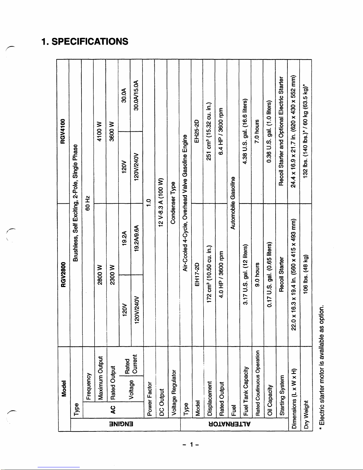
1
SPECIFICATIONS
I
0
a
3NI9N3
-
1-
Page 5

I
Iu
I
....
....
, ,
"
......
..............
',
....
"
_"
......
I
Model
RGV6100
TY
Pe Brushless, Self Exciting, 2-Pole, Single Phase
Frequency 60
Hz
Maximum Output 5800
W
Rated Output
4800
W
_-
. .-
....
1
Voltage
I
!:::nt
I
,
120V/240V
40N20A
Power Factor
DC Output 12 V-8.3 A (100
W)
~
Voltage Regulator
Condenser Type
I
Type Air-Cooled 4-Cycle, Overhead Valve Gasoline Engine
Model EH34D
Displacement
".
....
".
-
.
_"
....
....
338 cm3 (20.63 cu. in.)
Rated Output
I
8.0
HP
/
3600 rpm
I
Fuel Automobile Gasoline
Fuel Tank Capacity
Rated
Coutinuous
Operation
""
-
-
.
_
5.67
U.S.
gal.
(21.5 liters)
7.0 hours
".
..
.....
"_
".
Oil Capacity
I
0.32
US.
gal. (1.2 liters)
I
~
~~~~
Starting System
I
Recoil Starter and Optional Electric Starter
~ ~ ~~
-
...
_...-
-.
.
.
".
..
1
Dimensions
(L
x
W
x
H)
26.8
x
18.5
x
24.8 in. (680
x
470
x
630 mm)
-
172 Ibs.
(180
Ibs.)*
/
78 kg (81.5 kg)"
...
,
."
...
,
...
*
Electric starter motor
is
available
as
option.
Page 6
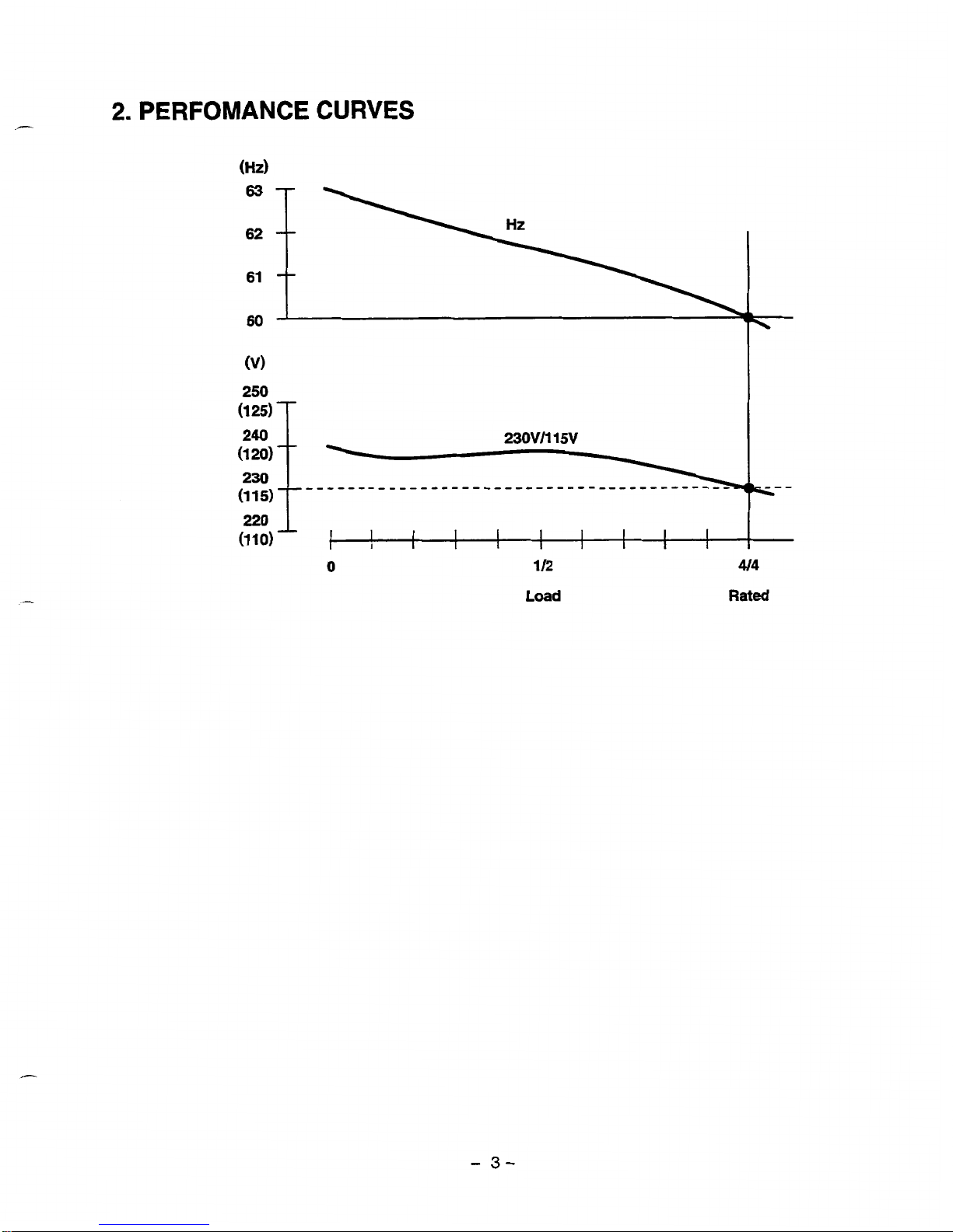
2.
PERFOMANCE
CURVES
(1
20)
(1 15)
"""""""""""~""
220
1
(1
10)
c
I
I
I
I
I I
I
I
I
1
I
I
0
112
Load
4/4
Rated
-
3-
Page 7
DC
OUTPUT
DC
Voltage
.................
12
V
DC
Ampere
................
8.3
A
DC
output
...................
100
W
The voltage curve shown in the left indicates the characteristic
of
DC
output when charging a battery.
The voltage
may
be
decreased
by
20%
when the resistance load is applied.
NOTE
:
If
is
possible fo use both
DC
and
AC
outputs simultaneously
up
to the rafed output
in
total.
-
4-
Page 8

-
3.
FEATURES
3-1
BRUSHLESS
ALTERNATOR
Newly developed brushless alternator eliminates troublesome brush maintenance.
3-2
CONDENSER TYPE VOLTAGE REGULATOR
A
trouble free condenser
type
voltage regulator ensures a stable voltage under
all
working conditions.
3-3
OIL
SENSOR
Oil sensor automatically shuts
off
the engine whenever the oil level falls down below the lower limit to
protect the engine from seizure.
3-4
QUIET OPERATION
Robin
RGV
series generator delivers a quiet operation with
:
A
large super silent muffler.
A
quiet 4-stroke Robin Rro
OHV
engine.
A
silent cyclone air cleaner.
3-5
NO
RADIO
NOISE
Noise suppressor spark plug is equipped standard to prevent radio frequency interference.
3-6
LARGE FUEL TANK
The large fuel tank allows more than
7
to
10
hours of continuous operation which is sufficient for a half
day or one day work without refueling.
3-7
RUGGED TUBULAR FRAME
Full cradle type rugged tubuler frame protects the generator all around.
3-8
COMPACT AND LIGHT WEIGHT
Newly developed brushless alternator enabled the
RGV
generators to be very compact in size and light
in weight.
-
5-
Page 9
3-9
MINIMAL MAINTENANCE
*
A
brushless alternator release the operator
from
periodical
brush
maintenance.
A
trouble free condenser
type
voltage regulator.
A
drip-proof
alternator design.
*
No-fuse circuit breakers.
*
An
electronic pointless ignition system.
A
dust-proof
cyclone air cleaner.
3-1
0
LONG-LIFE
DURABILITY
The heavy-duty 4 stroke Robin
Rro
OHV
engine and virtually maintenance-free brushless alternator
ensure greater durability
with
:
A
brushless alternator
with
a condenser voltage regulator.
Full
rubber mount
in
a
sturdy
tubular frame.
*
A
forged steel crankshaft supported
by
two
main ball bearings.
A
pointless electronic ignition system.
A
cast-iron cylinder liner.
A
forged
aluminum connecting
rod.
-
6-
Page 10
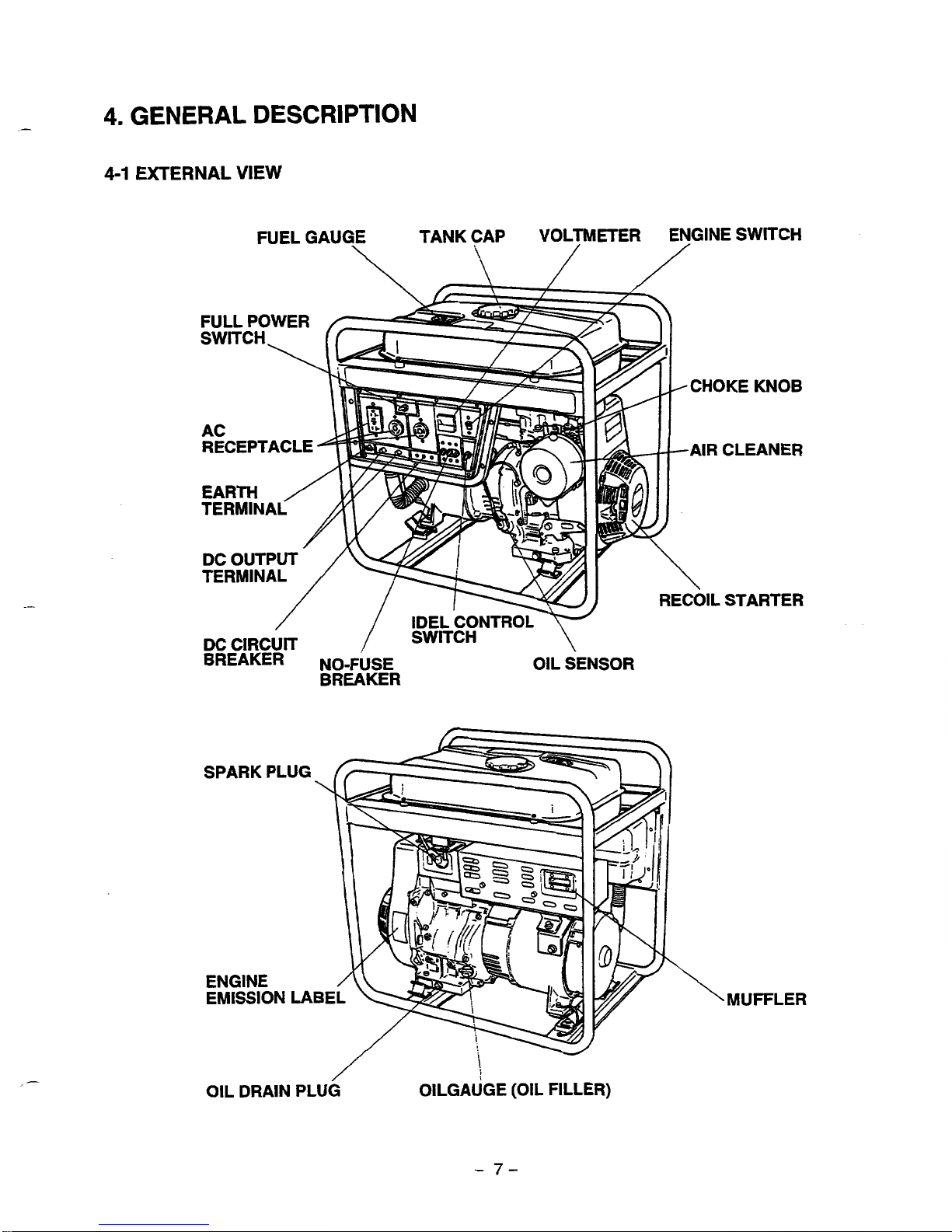
4.
GENERAL
DESCRIPTION
4-1
EXTERNAL
VIEW
FUEL GAUGE TANK CAP VOLTMETER ENGINE SWITCH
\
\
//
i
RECEPTACLE
EARTH
TERMINA
FULL POWER
CHOKE KNOB
AIR CLEANER
RECOIL STARTER
MUFFLER
L
/
OIL DRAIN PLUG OILGAUGE
(OIL
FILLER)
-
7-
Page 11
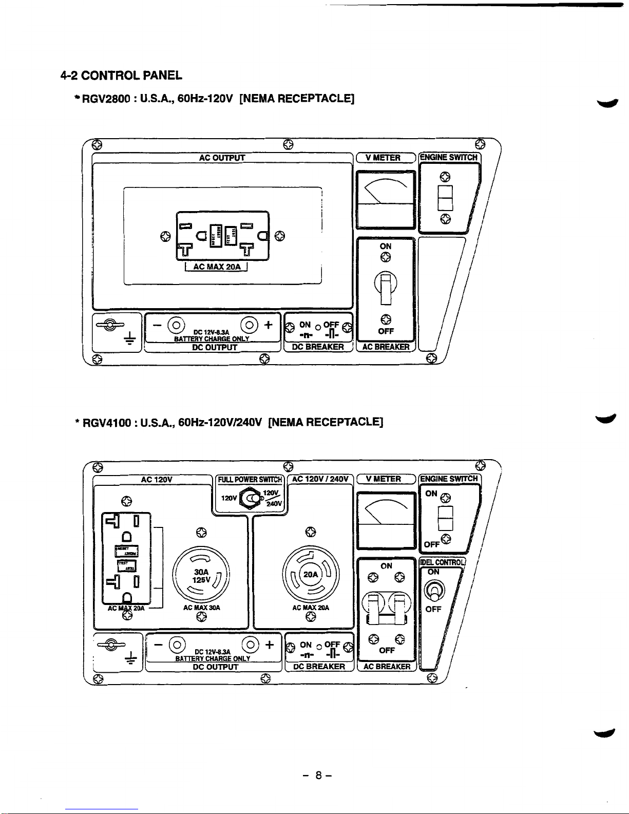
4-2
CONTROL
PANEL
RGV2800
:
U.S.A.,
60Hz-120V
[NEMA RECEPTACLE]
-
8-
Page 12
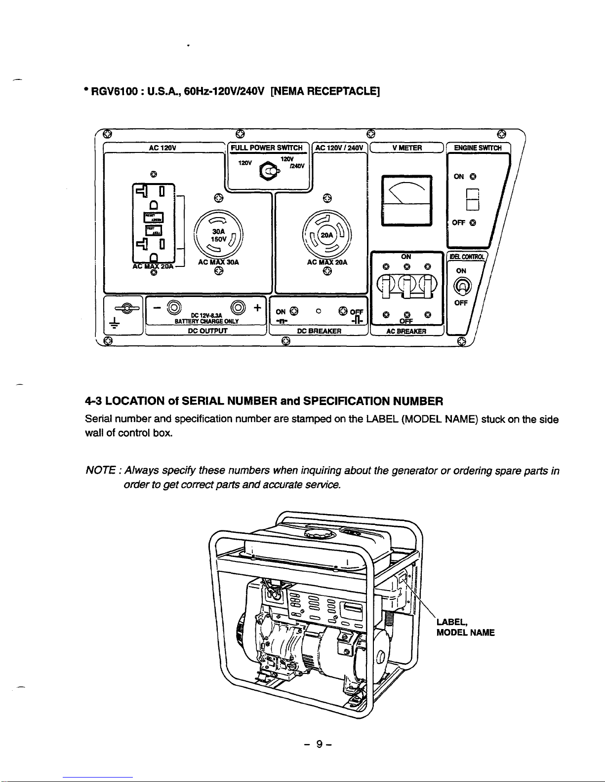
RGV6100 : U.S.A.,
60Ht-l20V/240V
[NEMA
RECEPTACLE]
-/
V
METER
0
4-3
LOCATION
of
SERIAL NUMBER
and
SPECIFICATION NUMBER
Serial number and
specification
number
are
stamped on the
LABEL
(MODEL
NAME)
stuck on the side
wall
of
control
box.
NOTE
:
Always specify these numbers when inquiring
about
the generator or ordering spare parts in
order to get
correct
parts
and accurate service.
-
9-
Page 13
5.
CONSTRUCTION
AND
FUNCTION
5-1
CONSTRUCTION
END COVER
\
\
!
BALL
BEARING
STATOR COMPLETE
ROTOR
COMPLETE
\
\
I
\
i
/
REAR
COVER
\,
STATORCOVER CRANKSHAFT
\\
',
\
'1
'\
\
i
i
MOUNT
RUBBER
jl
I
!/
:i
II
i
I
I
I
I
I
//
I
THROUGH
BOLT
COVER
BOLT
Fig.
5-1
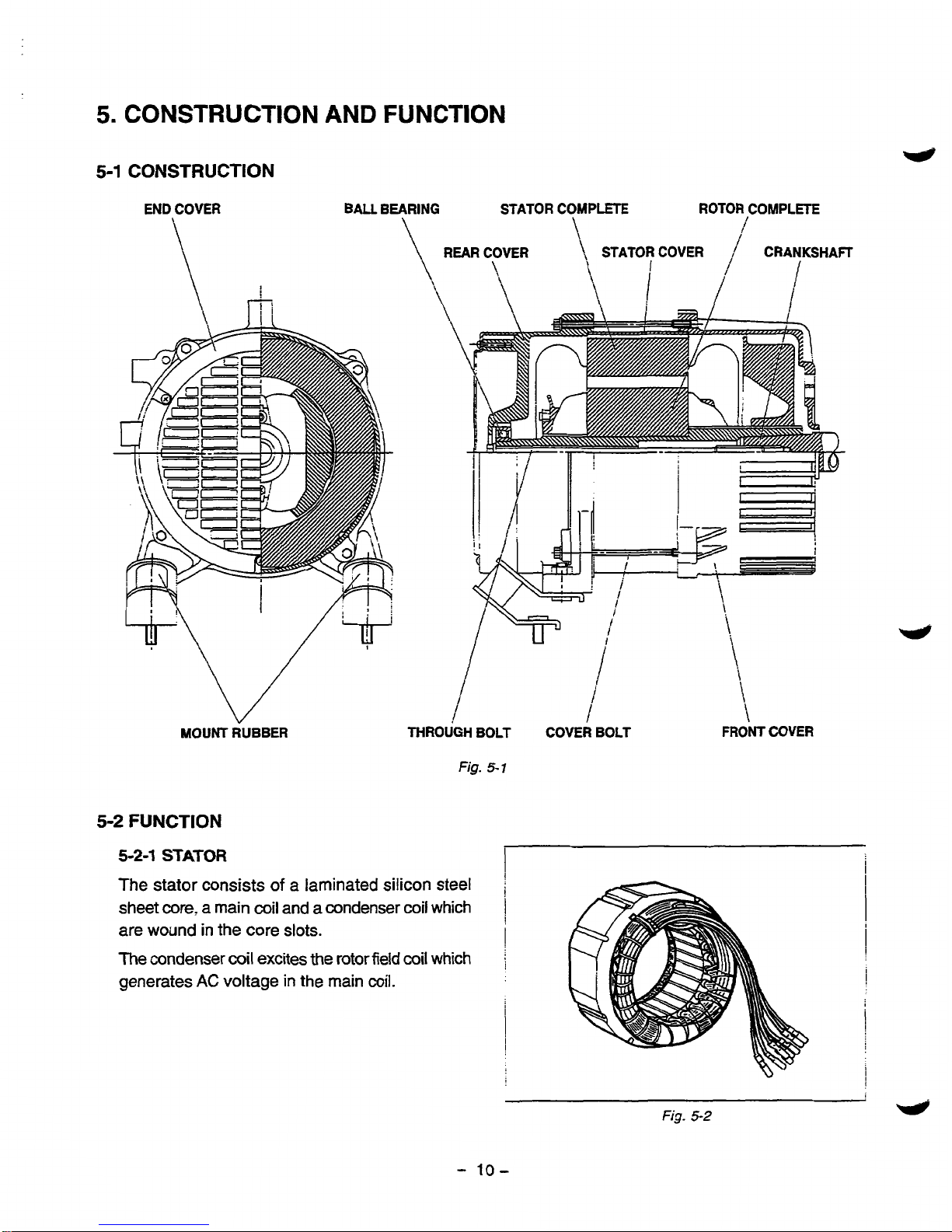
5-2
FUNCTION
5-2-1
STATOR
The stator consists
of
a
laminated silicon steel
sheet core, a main coil and
a
condenser coil which
are wound in the core slots.
The condenser coil excites the rotor field
coil
which
generates
AC
voltage in the main
coil.
I
1
\
\
FRONT
COVER
Fig.
5-2
w
-
10-
Page 14
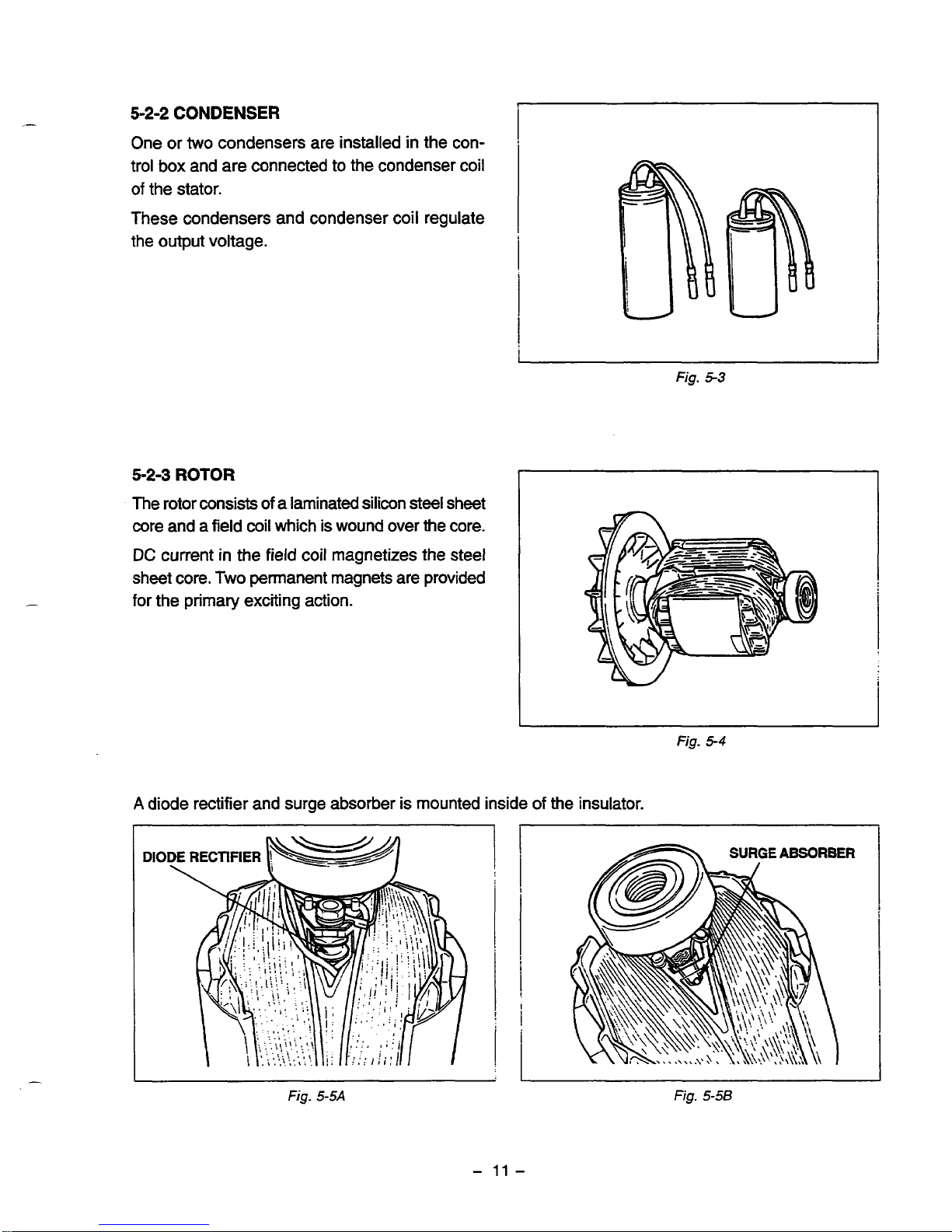
5-2-2
CONDENSER
One or
two
condensers are installed in the con-
trol
box
and are connected to the condenser coil
of
the stator.
These condensers and condenser coil regulate
the output voltage.
5-2-3
ROTOR
The rotor consists
of
a
laminated silicon steel sheet
core and a field coil which is wound over the core.
DC
current in the field coil magnetizes the steel
sheet core.
Two
permanent magnets are provided
for the primary exciting action.
Fig.
5-3
Fig.
5-4
A
diode rectifier and surge absorber is mounted inside of the insulator.
DIODE \ RECTIFIER
bw&
I
Fig
5-5A
Fig.
5-58
-
11
-
Page 15
5-2-4
NO-FUSE
BREAKER
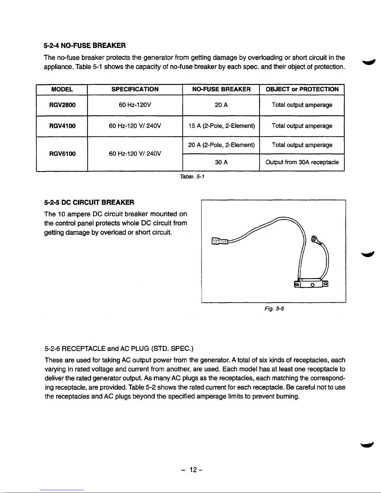
The no-fuse breaker protects the generator from getting damage by overloading or short circuit in the
appliance. Table
5-1
shows
the
capacity of no-fuse breaker by each spec. and their object
of
protection.
w
IpMO~~~"l
SPECIFICATION
RGV2800
60
Hz-120V
RGV4100
60
HZ-1
20
V/ 240V
RGV6100
60
HZ-120 V/ 240V
I
I
NO-FUSE BREAKER
OBJECT
or
PROTECTION
20
A
Total
output amperage
15
A
(2-Pole, 2-Element) Total
output
amperage
20
A
(PPole, 2-Element) Total output amperage
30
A
Output
from
30A receptacle
Table.
5-7
52-5
DC
CIRCUIT BREAKER
The
10
ampere
DC
circuit breaker mounted on
the control panel protects whole
DC
circuit from
getting damage
by
overload or short circuit.
I
j
j
Fig.
5-6
5-2-6
RECEPTACLE
and
AC
PLUG
(STD.
SPEC.)
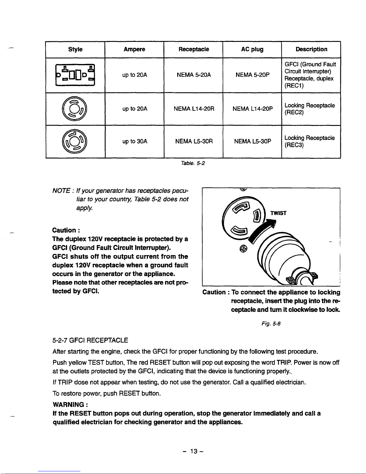
These are used for taking
AC
output power from the generator. A total of six kinds of receptacles, each
varying in rated voltage and current from another, are used. Each model has at least one receptacle to
deliver the rated generator output.
As
many
AC
plugs as the receptacles, each matching the correspond-
ing receptacle, are provided. Table
5-2
shows the rated current for each receptacle.
Be
careful
not
to use
the receptacles and
AC
plugs beyond the specified amperage limits to prevent burning.
-
12
-
Page 16
Style Description
AC
plug
Receptacle
Ampere
GFCl
(Ground Fault
Circuit Interrupter)
(RECi)
b5q
NEMA
L14-20P
NEMA
L14-20R
UPt020A
@
NEMA
5-20A
up
to
20A
NEMA
5-20p
Receptacle, duplex
Locking Receptacle
up
to
30A
(REC3)
NEMA L5-30P NEMA L5-30R
Locking Receptacle
Table.
5-2
NOTE
:
If
your generator
has
receptacles pecu-
liar
io
your
countv,
Table
5-2
does not
apply.
Caution
:
The duplex
120V
receptacle
is
protected
by
a
GFCl (Ground Fault Circuit Interrupter).
GFCl shuts
off
the output current from the
duplex
120V
receptacle when a ground fault
occurs
in
the generator or the appliance.
Please
note that other receptacles are not
pro-
tected by GFCI.
Caution
:
To
connect the appliance to locking
receptacle, insert the plug into the
re-
ceptacle and turn
it
clockwise
to
lock
Fig.
5-8
5-2-7
GFCl RECEPTACLE
After starting the engine, check the
GFCl
for proper functioning by the following test procedure.
Push yellow
TEST
button,
The
red RESET button
will
pop out exposing the word
TRIP.
Power
is
now
off
at the outlets protected by the
GFCI,
indicating that the device is functioning properly..
If
TRIP
dose not appear when testing, do not use the generator.
Call
a qualified electrician.
To
restore power, push RESET button.
WARNING
:
If
the
RESET
button pops
out
during operation, stop the generator immediately and call
a
qualified electrician for checking generator and the appliances.
-
13-
Page 17
5-2-8
CONNECTING
TO
DOMESTIC CIRCUITS (HOUSE WIRING)
e
WARNING
:
All
Robin generators are a neutral ungrounded
type.
If
a
generator is to be connected to residential or commercial power lines, such as a stand-by
power source during power outage, all connections must
be
made by a licensed electrician.
Failure
in
connection may result in death, personal injury, damage to generator, damage to appli-
ances, damage to the building's wiring or
fire.
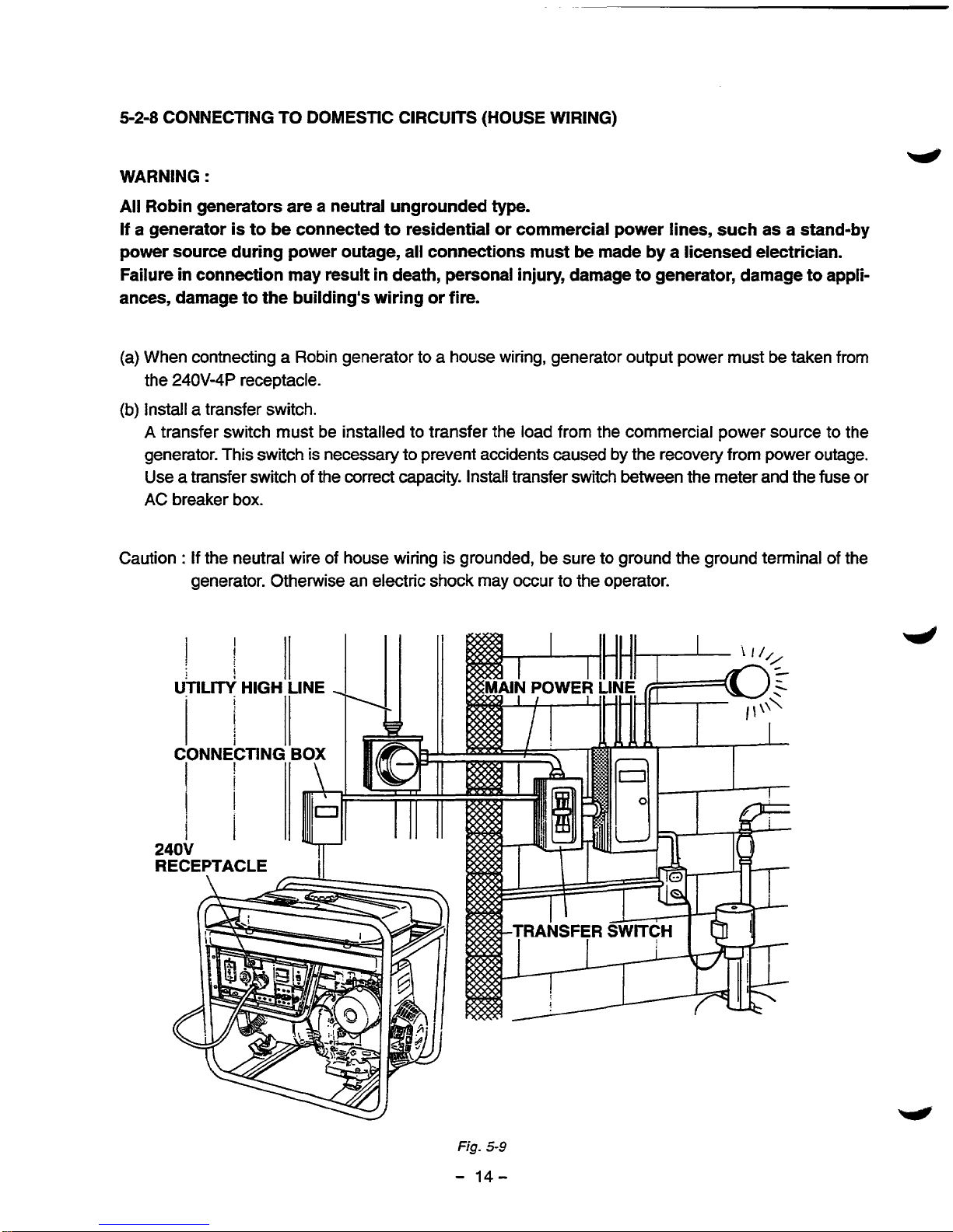
When contnecting a Robin generator to a house wiring, generator output power must
be
taken from
the
24OV-4P
receptacle.
Install a transfer switch.
A
transfer switch must be installed to transfer the load from the commercial power source to the
generator. This switch
is
necessary to prevent accidents
caused
by
the recovery from power outage.
Use
a
transfer switch of the correct capacity. Install transfer switch between the meter and the fuse
or
AC
breaker
box.
Caution
:
If
the neutral wire of house wiring
is
grounded, be sure to ground the ground terminal
of
the
generator. Otherwise an electric shock may occur to the operator.
Fig.
5-9
-
14-
Page 18

Fig.
5-
10
(c) Operating the generator.
Set the full power switch to
120V/
240V
side.
Turn the house
AC
breaker
off
before starting
the
generator.
Start the generator and warm
it
up.
Turn the house
AC
breaker on.
Caution
:
Do
not start the generator with electrical appliance
(s)
connected and
with
their switches on.
Otherwise the appliance
(s)
may be damaged by the surge voltage at starting.
-
15-
Page 19
5-3
GENERATOR OPERATION
PERMANENT
MAGNET
STATOR
I
L
""""
I
Fig.
5-
11
5-3-1
GENERATION
Of
NO-LOAD VOLTAGE
(I)
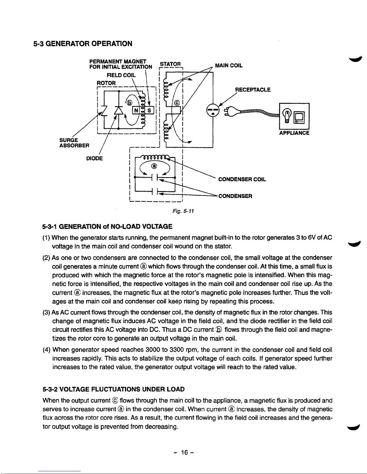
When the generator starts running, the permanent magnet built-in to the rotor generates 3 to
6V
of
AC
voltage in the main coil and condenser coil wound on the stator.
w
(2)
As
one or
two
condensers are connected to the condenser coil, the small voltage at the condenser
coil generates a minute current @which flows through the condenser coil. At this time, a small flux is
produced with which the magnetic force at the rotor's magnetic pole is intensified. When this magnetic force is intensified, the respective voltages in the main coil and condenser coil rise up.
As
the
current
(3
increases, the magnetic flux at the rotor's magnetic pole increases further. Thus
the
volt-
ages at the main coil and condenser coil keep rising
by
repeating this process.
(3)
As AC
current flows through the condenser coil, the density
of
magnetic flux
in
the rotor changes. This
change of magnetic flux induces
AC
voltage in the field coil, and the diode rectifier in the field coil
circuit rectifies this
AC
voltage into
DC.
Thus
a
DC
current
8
flows through the field coil and magne-
tizes the rotor core to generate an output voltage in the main coil.
(4)
When generator speed reaches
3000
to
3300
rpm, the current in the condenser coil and field coil
increases rapidly. This acts
to
stabilize the output voltage of each coils.
If
generator speed further
increases to the rated value, the generator output voltage will reach to the rated value.
5-3-2
VOLTAGE FLUCTUATIONS UNDER LOAD
When the output current flows through the main coil to the appliance, a magnetic flux is produced and
selves to increase current
tzl
in the condenser coil. When current
!@
increases, the density of magnetic
flux across the rotor core rises.
As
a
result, the current flowing in the field coil increases and the genera-
tor output voltage is prevented from decreasing.
4
-
16-
Page 20
"
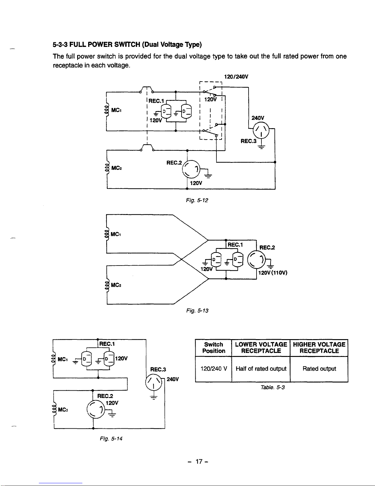
5-3-3
FULL
POWER
SWITCH
(Dual
Voltage
Type)
The
full
power switch is provided for the dual voltage type to take out the full rated power from one
receptacle
in
each voltage.
120f240V
r""
I
-
T
I
I
II
$-.
1
REC.3
6
-
-
I
12ov
I
Fig.
5-12
MC2
Fig.
5-
13
REC.1
REC.3
Switch
RECEPTACLE
RECEPTACLE Position
HIGHER
VOLTAGE LOWER VOLTAGE
120/240
V
Rated
output
Half
of
rated output
240V
Table.
5-3
-
Fig.
5-
14
-
17-
Page 21
Two main coils are wound over stator core. Each main coil outputs half the rated power at the lower
voltage
(1 20V).
These main coils are wound
to
be in the same phase. The full power switch reconnects
these main coils in parallel or
in
series.
e
Fig.
5-12
shows a circuit diagram. When the full power switch is set for single lower voltage indication
(120V),
the switch position is as indicated by the lower solid line in the diagram. Fig.
5-13
is a simplified
representation
of
this circuit, showing the
two
main coils connected in parallel.
In
this case, the higher
voltage
(240V)
at Rec. 3 cannot be taken out.
Rec.
2
for the lower voltage can output up to the rated
power (up to
30A
if
the rated current is over
30A),
and Rec. 1 can output up to a total
of
15A.
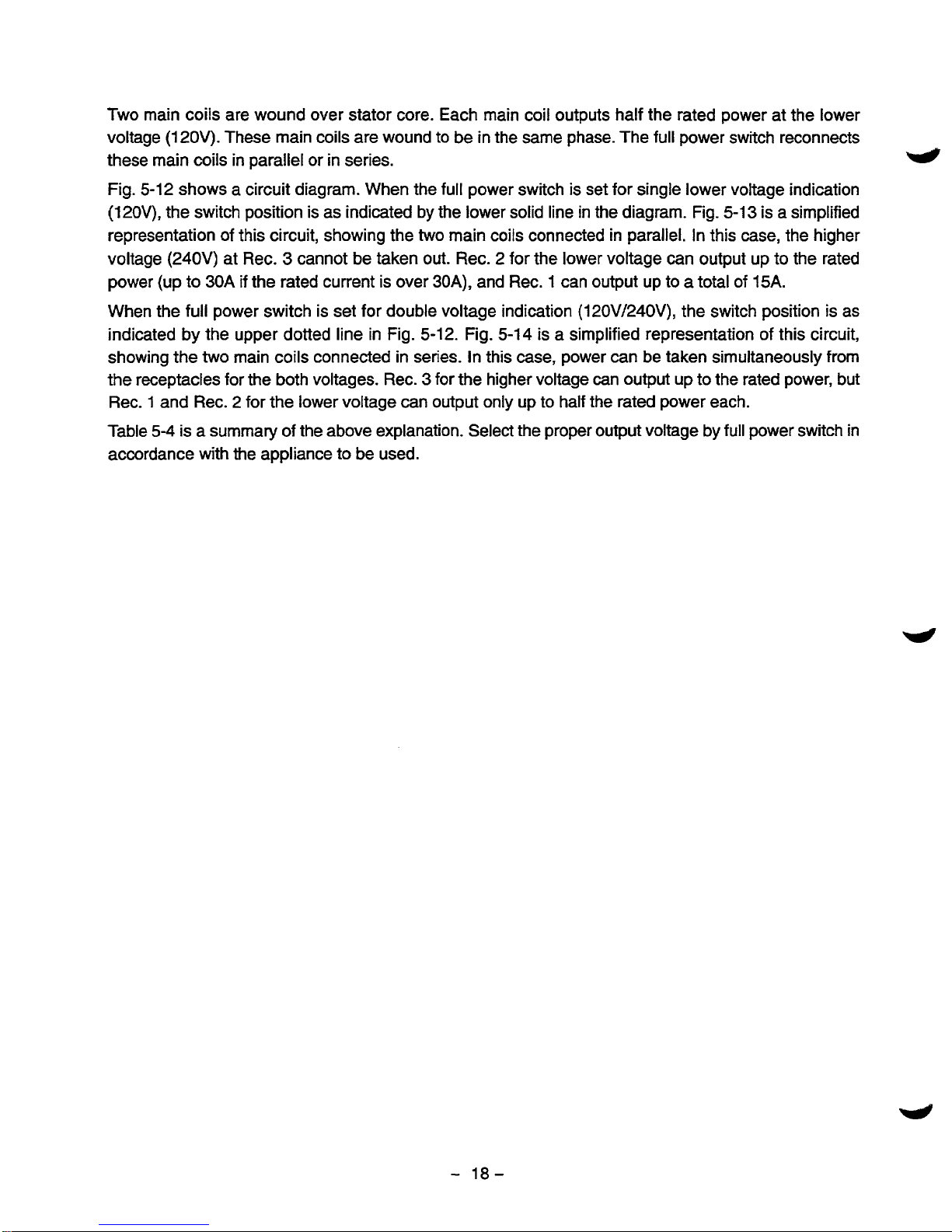
When the full power switch is set for double voltage indication
(120V/240V),
the switch position is as
indicated by the upper dotted line in Fig.
5-12.
Fig.
5-14
is
a
simplified representation
of
this circuit,
showing the two main coils connected
in
series. in this case, power can be taken simultaneously from
the receptacles for the both voltages. Rec.
3
for the higher voltage can output up to the rated power, but
Rec.
1
and Rec. 2 for the lower voltage can output only up to half the rated power each.
Table
5-4
is a summary
of
the above explanation. Select the proper output voltage by full power switch in
accordance with the appliance to be used.
-
18-
Page 22

5-4
OIL
SENSOR
5-4-1
DESCRIPTION
*
The oil sensor mainly functions to detect position of the surface of engine oil in the crankcase
of engines for general use and to stop the engine automatically when the oil level goes down
below the lower limit specified. This prevents seizure of engine from occurring due to insufficient
amount of oil
in
the crankcase.
Since the sensor has been designed to consume
a part of power supplied to the igniter to energize its electronics circuit, any other external
power supply is not necessary
so
that
it
can
be
mounted at the oil filler port.
Fig.
5-15
Introduction of newly developed sensing principle features super durability and no change with the
passage of time as it does not use any moving part.
Merits due to introduction of electrical conductivity detection are as follows
;
%,
It has resistance to mechanical shocks and property of no change with the passage of time as
3.
At the same time,
it
is capable of detecting the
oil
level stably as
it
is not influenced by engine
sensing element consists simply of electrodes having no moving parts.
vibrations.
No
error
occurs
due to foam and flow of the oil.
n
!z
Influence against the ignition system or the electronics units can be neglected because an electric
current supplied to the sensor can be decreased.
542
PRINCIPLE
OF
SENSING
OIL
LEVEL
There is a great difference between electric resistance of air and that of oil. Since the resistance of air is
far higher than that of oil, more electric current passes through the oil than through the air, although
absolute value of
the
current is very small. The sensor detects this current difference and make use of it.
The sensor judges the
oil
quantity, by comparing a current flowing across a pair of electrodes (inner and
outer) with the reference, in such a way that
if
a current flows between the electrodes more than the
reference, sufficient oil is in the crankcase, on the other hand,
if
a current flows less than the reference,
oil is not sufficient. Since an electric current is flown to detect oil quantity, this is called the ”electrical
conductivity detection” type of sensor. The oil level to be detected is determined by the length of electrodes and their mounting positions with the engine.
5-4-3
HOW
IT
OPERATES
[Power
supply]
The sensor makes use of a part of primary power source for ignition
of
the engine (igniter) to drive the
sensor circuit. Power to the sensor can usually be derived from the %top button”
by
branching wires out.
-
19-
Page 23

[Judgement
of
oil
level]
When sufficient
oil
is in the crankcase, both of inner and outer electrodes are immersed
in
the oil through
which current
flows
across the electrodes. The sensor judges that oil in the crankcase is sufficient. When
oil level goes down and the inner electrode is exposed
to
the air due to consumption of oil, no current flow
between the electrodes as air is considered to be electrically nonconductive. The sensor in this case
judges that oil
is
insufficient.
4
[Decision
of
oil
shortage]
Oil level at the electrodes may
go
down momentarily probably due to the engine being slanted or affected
by vibration even if
a
sufficient oil is
in
the crankcase. For that reason, the sensor has an electronic timer
circuit
to
prevent
it
from interpreting as short of oil when amount
of
oil
is
sufficient. The sensor has been
designed
so
that the engine is to be stopped only when oil-shortage is detected for 5 seconds uninter-
rupted. The timer employs
an
integration circuit and
it
is to be reset when the inner electrode is soaked
in
the oil again before
the
sensor decides
it
as oil-shortage. The oil level where the sensor decides as oil-
shortage, when oil level goes down gradually, is called "threshold level".
[Automatic
stop
of
engine]
When the sensor decides as oil-shortage,
it
makes the engine to stop running automatically for protec-
tion
of
engine. Once the stopping circuit is activated,
it
keeps functioning until
it
confirms that the engine
has made a complete stop, then the circuit stops functioning automatically.
5-44
BLOCK
DIAGRAM
OF
THE CIRCUIT
Power circuit
Igniter
Inner
pole
-
-
circuit
circuit
Deley circuit
Detection Stopping
oil
I
Outer
pole
Engine ground
Fig.
5-
16
a
Power circuit
..........
This
rectifies a part
of
power to the igniter and regulates it to supply the stabi-
lized power to necessary circuits.
,1
-
20-
Page 24

3
Detection circuit
.....
This detects quantity of oil, sufficient or not, according to difference of electric
resistance across inner and outer electrodes.
Delay circuit
_..........
This his prevents the sensor from making an unnecessary stop of the engine
by momentary lowering
of
the oil level due to the engine being slanted or
affected by vibration in spite
of
sufficient oil in the crankcase.
n
:x.
Stopping circuit
......
This automatically stops the engine running.
5-4-5
CAUTIONS TO BE TAKEN ON HANDLING THE SENSOR
(1)
Oil sensor unit
Be sure not to damage each wire. Broken or short-circuited power supply wires and/or a grounding wire in particular may lead to malfunction or breakdown.
@
The sensor is not interchangeable from engine to engine because the sensor is to be exclusively
installed individually in each engine employed.
(2)
Mounting and wiring
of
oil sensor unit
@
Although this has been designed to have enough antinoise properties in practical use,
do
not
route the Sensor wirings in the vicinity of noise-generating sources such
as
ignition plugs or high
voltage cords. This may cause malfunction or breakdown.
a
Since capacity of power source is limited, current flown in the electronic circuit
of
the sensor is
kept
as
low
as possible. Be sure to use terminals with a high contact reliability of more than that
of
tinned terminals.
(3)
Operation
of
oil sensor
13
If
operating with the engine kept tilted,
oil
surface inside
of
the engine varies and the correct oil
level can not to be detected which in turn obstructs the preventing function
of
engine seizure.
Operate the engine by keeping it level.
-38
When starting the engine with an insufficient oil in the crankcase, engine starts once then it stops
automatically after
it
runs for 5 seconds.
.z,
When the engine has been stopped by the oil sensor, voltage remained in the electronic circuit
prevents the sensor from being restarted for
3
seconds after the engine stop.
Try
to restart the
engine after
3
seconds or more.
-
21
-
Page 25

1.
Use extreme caution near fuel. A constant danger of explosion or fire exists.
Do
not fill the fuel tank while the engine is running.
Do
not smoke or use open flame near the fuel tank.
Be careful not to spill fuel when refueling.
If
spilt, wipe it and let dry before starting the engine.
2.
Do
not place inflammable materials near the generator.
Be careful not to put fuel, matches, gunpowder, oily cloth! straw, and any other inflammables near the
generator.
3.
Do
not operate the generator in a room, cave or tunnel. Always operate
in
a well-ventilated
area.
Otherwise the engine may overheat and also, the poisonous carbon monoxide contained in the exhaust gases will endanger human lives. Keep the generator
at
least 1 m
(4
feet) away from structures
or facilities during use.
4.
Operate the generator on a level surface.
If
the generator is tilted or moved during use, there is a danger of fuel spillage and a chance that the
generator may tip over.
5.
Do not operate with wet hands or in the rain.
Severe electric shock may occur.
If
the generator is wet by rain or snow, wipe
it
and thoroughly
dry
it
before starting. Don’ t pour water over the generator directly nor wash it with water. If the generator is
wet with water, the insulations will be adversely affected and may cause current leakage and electric
shock.
-4
6.
Do
not connect the generator to the commercial power lines.
This may cause a short-circuit or damage to the generator. Use
a
transfer switch (Optional parts) for
connecting with indoor wiring.
NOTE
I
The parts numbers of the transfer switches and
of
the plastic
box
to
store them are
as
shown in
Table
6-
7.
Table.
6-
1
7.
Be sure to check and remedy the cause of circuit breaker tripping before resetting
it
on.
CAUTION
:
If the circuit breaker tripped
off
as
a result of using an electrical appliance, the cause
can be an overload or a short-circuit. In such a case, stop operation immediately and carefully
check the electrical appliance and
AC
plugs for faulty wiring.
.1
-
22-
Page 26

7.
RANGE
OF
APPLICATIONS
Generally, the power rating of an electrical appliance indicates the amount of work that can be done
by
it.
The electric power required for operating an electrical appliance is not always equal to the output wattage
of
the appliance. The electrical appliances generally have a label showing their rated voltage, frequency, and power consumption (input wattage). The power consumption of an electrical appliance is
the power necessary for using
it.
When using a generator for operating an electrical appliance, the power
factor and starting wattage must be taken into consideration.
In order to determine the right size generator, it is necessary to add the total wattage
of
all
appliances to
be connected to the unit.
Refer
to
the followings to calculate the power consumption of each appliance or equipment by its type.
(1)
Incandescent lamp, heater, etc. with a power factor of
1.0
Total power consumption must be equal to or less than the rated output of the generator.
Example
: A rated
3000W
generator can turn thirty 1
OOW
incandescent lamps on.
(2)
Fluorescent lamps, motor driven tools, light electrical appliances, etc. with a smaller power
factor
Select a generator with a rated output equivalent to
1.2
to 2 times
of
the power consumption of the
load. Generally the starting wattage of motor driven tools and light electrical appliances are
1.2
to
3
times lager than their running wattage.
Example
:
A
rated 250 W electric drill requires a
400
W
generator to
start
it.
NOTEl
:
If a power factor correction capacitor is not applied to the fluorescent lamp, the more power
shall
be
required to drive the lamps.
NOTE2
:
Nominal wattage of the fluorscent lamp generally indicates the output wattage of the lamp.
Therefore,
if
the fluorescent lamp has no special indication as to the power consumption, efi-
ciency should be taken into account as explained in Item
(5)
on
the following page.
(3)
Mercury lamps with a smaller power factor
Loads for mercury lamps require 2 to 3 times the indicated wattage during start-up.
Example
:
A
400
W
mercury lamp requires
800
W
to 1200 W power source to be turned on. A rated
3000
W
generator can power
two
or three
400
W
mercury lamps.
(4)
Initially loaded motor driven appliances such as water pumps, compressors, etc.
These appliances require large starting wattage which is 3 to 5 times of running wattage.
Example
: A rated
900
W
compressor requires a
4500
W
generator to drive it.
NOTEl : Motor-driven appliances require the aforementioned generator output only at the starting. Once
their motors are started, the appliances consume about
1.2
to 2 times their rated power con-
sumption
so
that the excess power generated
by
the generator can be used for other electrical
appliances.
NOTE2
:
Motor-driven appliances mentioned in items
(3)
and
(4)
vary in their required motor starting
power depending on the kind of motor and start-up load.
If
it is difficult to determine the optimum
generator capacw, select a generator with
a
larger capacity
-
23-
Page 27

(5)
Appliances without any indication as
to
power
consumption
Some appliances have no indication as to power consumption; but instead the work load (output) is
indicated. In such a case, power consumption is to be worked out according to the numerical formula
mentioned below.
1
(Output
of
electrical appliance)
(Efficiency)
=
(Power consumpition)
Efficiencies
of
some electrical appliances are as follows
:
Single-phase motor
................................
0.6
to 0.75 The smaller the motor, the
Fluorescent lamp
...................................
0.7 to
0.8
(
lower
the
efficiency-
)
Example
1:
A
40W fluorescent lamp means that its luminous output is 40W. Its efficiency is 0.7 and
accordingly, power consumption will be 40
+
0.7= 57W.
As
explained in Item
(2),
multiply
this power consumption value of
57
W by
1.2
to 2 and you will get the figure of the neces-
sary capacity of a generator.
In
other words, a generator with a rated output of
lOOOW
capacity can light nine to fourteen
40
W
fluorescent lamps.
Example
2
:
Generally speaking, a 400 W motor means that its work load is 400
W.
Efficiency of this
motor is 0.7 and power consumption will be 400+0.7=
570
W.
When this motor is used for
a motor-driven tool, the capacity
of
the generator should be multiple
of
570
W
by
1.2
to 3 as
explained in the Item
(3).
570
(W) x 1.2 to
3 = 684
(W)
to
171
0
(W)
MODEL
RGV6100
RGV4lOO RGV2800
d
Frequency
60
H
I
I
lncandesent
lamp,
heater, etc.
I
2300
W
I
3600
W
1
48oow
I
Fluorescent
lamp,
Motor-
approx.
approx.
approx.
driven
tool,
general-porpose
I
1800W
I
2400W
I
Mercury
lamp,
etc.
approx.
approx.
approx.
1
800W
1
1600W
Pump,
compressor,
etc.
approx.
1100
w
850
W
550
W
approx.
approx.
Table.
7-7
-
24-
Page 28

NOTES
:
Wring between generator and electrical appliances
7.
Allowable current of cable
Use a cable with an allowable current that is higher than the rated input current
of
the load (electrical
appliance). If the input current is higher than the allowable current of the cable used, the cable will
become excessively heated and deteriorate the insulation, possibly burning it out. Table 7-2 shows
cables and their allowable currents for
your
reference.
2.
Cable length
If
a long cable
is
used, a voltage drop occurs due to the increased resistance in the conductors de-
creasing the input voltage to the load (electrical product). As a result, the load
can
be damaged. Table
7-2 shows voltage drops per
700
meters of cable.
Sectional
area
/
mm3
Gauge
NoJ
wire
element
NoJ
mm
7 30
I
0.1
8
12
50
I
0.1 8
17
37
I
0.26
current / A
45
I
0.32
70
I
0.32
*
Resistance
0.51
7
0.332
Table.
7-2
Voltage
drop
indicates as V=
-
xRxIxL
100
Voltage drop
per
100
m
3A
18V
15V
12V
7.5V
5V
12.5
V
8
V
15A
12A
10A
8A
SA
3v
15v
12~
10v
av
5.o~
1.5
V
I
2.5
V
I
4
V I 5V
I
6.5V
1
7.5V
1v
5V
4v
3.5v
2.5v
2v
R
means resistance
(
Q
/
100
rn)
on the above table.
I
means electric current through the wire
(A).
L
means the length of the wire
(m).
The length
of
wire
indicates round length, it means twice the length from generator to electrical tools.
-
25-
Page 29

8.
MEASURING
PROCEDURES
8-1
MEASURING INSTRUMENTS
8-1-1
“Dr. ROBIN” GENERATOR TESTER
The “Dr. Robin” generator tester is exclusively
designed for fast, easy diagnosis and repair of
Robin generators. The “Dr. Robin” has the following features
:
(1)
Functions of voltmeter, frequency meter,
megger tester, capacitance meter and circuit
tester are combined in one unit.
(2)
Fast and easy readout by digital indicator.
(3)
Built-in automatic battery checker indicates the
time to change batteries.
(4)
Tester and accessories are installed in a handy,
sturdy case for easy carrying.
SPECIFICATIONS
I
MODEL
I
Dr.
Robin
I
IiNumber
I
388-47565-08
1
Measuring
Range
Voltage
3M
Q
Insulation Resistance
10
to
100
pF
Condenser Capacty
0.1
to
1.999
n
Resistance
25
to 70
Hz
Frequency
d
0
to
500
V
AC
Circuit Protector
Fuse
Power Source
2
x
6F44P (006P)
Dry
Cell
Battery
Accessories
Dimensions
(L
x W x
H)
Weight
285
mm
x200
mm
x
110
mm
1.6
kg
Test leads with needle probes
.
.
.
1
set
Test leads with jack
plugs
.
. .
1
set
Table.
8-7
The “Dr. Robin” generator tester can be ordered from Robin generator distributors by the following part
number.
Dr.
Robin
Part
Number
:
38847565-08
If
you do not have a “Dr. Robin” generator tester, use the instruments described in the following section
for checking generator parts.
-1
-
26-
Page 30

8-1-2
INSTRUMENTS
(1)
VOLTMETER
AC
voltmeter is necessary. The approximate
AC
voltage ranges
of
the voltmeters to be used
for
various types
of
generators are
as
follows:
0
to 15OV
:
Type
with an output voltage
of
110
0
to 300V : Type with an output voltage
of
220,
0
to 1 50V, 0 to 330V
:
Dual
voltage type
or
120V
230
or 240V
(2) AMMETER
AC
ammeter is necessary. An AC ammeter
with a range that can be changed according
to the current rating
of
a given generator is
most desirable.
(About
1
OA,
20A, 1 OOA)
(3)
FREQUENCY
METER
Frequency range
:
About
45
to 65Hz
NOTE
:
Be
careful of
the
frequency meter's
input
voltage range.
FOR
AC
FOR AC
Fig.
8-3
Fig-
8-4
-
27-
Page 31

(4)
CIRCUIT TESTER
Used
for measuring resistance, etc.
Fig.
8-5
(5)
MEGGER
TESTER
I
Used
for
measuring generator insulation
re-
sistance. Select one with testing vottage range
of
500V.
(6)
TACHOMETER
Use the contactless
type
tacho meter.
Fig.
8-6
Fig.
8-7
-
28-
Page 32

8-2
AC
OUTPUT
MEASURING
Fig.
8-8
Use a circuit like the shown in Fig.8-8
for
measuring
AC
output. A hot plate
or
lamp with a power
factor
of
1
.O
may be used as a load. Adjust the load and
rpm.
and check that the voltage range
is
as specified in
Table
8-2
at the rated amperage and rated
rpm.
I
I
Rated
voltage
120
v
240
V
I
Voltage range
I
108-132V
I
216
-264V
I
Table.
8-2
8-3
DC
OUTPUT
MEASURING
I
1
I
Measurement
of
DC
output is executed with the switch turned
ON
while the current
is
regulated at
8.3A
by adjusting the load to the generator.
If
the voltage
is
within the range
from
6V
to
14V,
the voltage
output
is
normal.
NOTE
:
If
a
battery
is
connected
as
a
load to
the
generator, the
DC
output voltage
will
increase
by
approximately 1 to
2
V.
Therefore, carefully observe the electrolyte level and
do
not overcharge
the battery.
-
29-
Page 33

8-4
MEASURING
INSULATION
RESISTANCE
Use a
"Dr.
Robin" generator tester in megger tester
mode or use a megger tester to check the insulation resistance. Connect a megger tester to one
of receptacle output terminals and the ground terminal, then measure the insulation resistance.
An
insulation resistance
of
1
megohm or more is nor-
mal. (The original insulation resistance at the time
of
shipment from the factory is
10
megohm or
more.)
If
it
is less than 1 megohm, disassemble
the generator and measure the insulation resistance
of
the stator, rotor and control panel indi-
vidually.
NOTE
:
Turn
on
the no-fuse breaker before
mea-
surement.
*
STATOR
(1)
Measure the insulation resistance between
BLUE lead and the core.
(2)
Measure the insulation resistance between
WHITE lead and the core.
(3)
Measure the insulation resistance between
YELLOW
lead
and
the core.
(4)
Measure the insulation resistance between
BROWN lead and the core.
ROTOR
Measure the insulation across one of the soldered
terminals
of
the rotor and the core.
Fig.
8-11
Fig.
8-12
-
30-
Page 34

CONTROL
PANEL
I
Measure the insulation resistances between the
live
parts
and
the
grounded parts.
I
Fig.
8-
13
Any part where the insulation resistance is less than
1
M
SZ
has faulty insulation, and may cause electric
leakage and electric
shock.
Replace the faulty
part.
.
.
-
31
-
Page 35

9.
CHECKING
FUNCTIONAL
MEMBERS
9-1
VOLTMETER
Check the voltmeter
if
it
is turned on by applying
specific voltage. Voltmeter cannot be checked with
circuit tester because its resistance is too large.
3
Check that no disconnection nor short-circuit
occurs with
a
tester, and the internal resistance
is around
OOk
ohms normally.
3
Turn on the commercial power supply-input
and check the indication.
9-2
AC RECEPTACLES
VOLTMETER
Fig.
9-1
Using a "Dr. Robin" or a circuit tester, check continuity between the two terminals at the rear of the
AC
receptacles while the receptacle is mounted on the control panel. When continuity is found between the
output terminals
of
the receptacle with a wire connected across these terminals, the AC receptacle is
normal. When the wire is removed and no continuity is found between these terminals, the receptacles
are
also
normal.
It
WIRE
i
AC RECEPTACLE
9-3
NO-FUSE
BREAKER
Fig.
9-2A
Fig.
9-28
1
Check continuity between each
of
two
terminals
at the rear of the no-fuse breaker while it is
mounted on the control panel. Normally, there
is
continuity between each of the
two
when the no-
fuse breaker is on while there
is
no continuity when
the no-fuse breaker
is
off.
\
I
i
NO-FUSE BREAKER
\
Fig.
9-3
-
32-
Page 36

9-4
STATOR
Disengage connectors on the wires from stator
and check the resistance between wires with a
"Dr. Robin" or a circuit tester referring to the fol-
lowing table.
4
Fig.
9-4
~~
Specification
AC
Winding
Condenser
Winding
MODEL
Hz
Yellow I Yellow Black
/
Blue
White
I
Red
Voltage
RGV2800
1.67
0.58
0.58
120 V, 120 VI240 V
60
RGV4100
0.99
0.52
0.52
120
v,
120
v/240
v
60
RGV6100
0.58 0.25
0.25
120 V, 120 V/240
V
60
Table.
9-1
NOTE : If the circuit tester is not sufficiently accurate, it may not show the values given and may give
erroneous readings. Erroneous readings
will
also
occur when there is a wide variation of resistance among coil windings or when measurement is performed at ambient temperatures different from
20
"C
(68
"0.
-
33-
Page 37

9-5
ROTOR
ASSEMBLY
(1)
Using a "Dr. Robin" or a circuit tester, measure the resistance
of
the field coil at the terminals.
(Q)
MODEL
RGV6100 RGV4100
RGV2800
RESISTANCE
1.60
Q
1.77
a
1.75
Q
Table.
9-2
NOTE
7
:
Because a diode is soldered
to
the coil ends at
the terminals, resistance may be measured only
when tester probes touche the terminals in one
combination
of
polarity. Therefore, if no resistance
reading appears,
try
checking in reverse polarity.
NOTE
2
:
If
the
circuit tester is not suff7ciently accurate, it
may not show the values given and may give erroneous readings. Erroneous reading will
also
occur when there
is
a wide variation
of
resistance
among coil windings or when measurement is
performed
at
ambient temperatures different from
20
"C
(68
=F).
9-6
CONDENSER
Fig-
9-5
Use
a
"Dr.
Robin" in capacitance meter mode to check the capacity
of
condensers.
\
(I
\
!
CONDENSER
I
1:
!
i
I
!
i
I
I
\
CONDENSER
Fig.
46A
Type
RGV2800
Fig.
9-6B
Type
RGV4700,
RGV6100
NOTE
:
Be sure
to
discharge condensers by shorting condenser leads each other before checking their
capacitance, or the accurate reading cannot be obtained.
-
34-
Page 38

NORMAL CAPACITY
OF
CONDENSER
RGV2800 RGV4100 RGV6100
20pFx2 28pFx2
Table.
9-3
If
such an instrument
is
unavailable, the condenser can be checked
by
replacing with a new one. If the
generator performs good with new condenser, the cause of trouble is defect in original condenser.
9-7
DIODE
RECTIFIER
DIODE
RECTIFIER
Brown
Brown/
Whim
1
Brown
Brown
/
White
fig.
9-7
CIRCUIT TESTER
Fig.
9-8
Circuit inside of the diode rectifiers is as shown in
Fig.
9-7.
Check continuity between each terminal by
using a circuit tester as shown in Fig.
9-8.
The rectifier is normal when condtinuity is as follows:
Checkina table for analogue circuit tester.
Analogue circuit tester
Apply black (minus) needle
of
the circuit tester
Brown Brown
I
Brown
I
-
I
NO
continuity
I
NO
continuity I Continuity
I
Apply red (plus) needle
of
the circuit tester
Brown
Continuity
No
continuity
-
No
continuity
I
Continuity Continuity
Orange
-
Continuity
Brown /White
-
No
continuity
No
continuity
No
continuity
Table.
94-1
-
35-
Page 39

Checkina table
for
diaital
circuit
tester.
~~ ~ ~~~~ ~ ~ ~ ~~
Apply
red (plus) needle
of
the
circuit tester
~~ ~~
w
Digital circuit tester
Brown Brown
Brown
/
White
Orange
I
~ ~
Brown
Continuity Continuity Orange
Continuity
No
continuity
-
No
continuity Brown
Continuity
No
continuity
No
continuity
-
-
Continuity
Apply
black
(minus) needle
of
the
circuit tester
Brown /White
-
No
continuity
No
continuity
No
continuity
NOTE
1
:
Because of the difference of measuring method between the analogue circuit tester and the
digital circuit tester, polar@ of tester needles should be reversed.
NOTE
2
:
"Continuit)r means forward direction characteristics of the diode, and different from short
circuit condition (in which a pointer of the tester goes
out
of its normal scale), shows resistance
to some extent. When results of the checking indicates failure even in one section, replace
with a new one.
NOTE
3
:
Simpson brand analogue testers have the characteristics as same as the digital circuit testeL
9-8
OIL
SENSOR
j
~4
(1)
Disconnect
two
(2)
wires comming from the
(2)
Loosen gine. the sensor to remove it from the en-
:
i
pi
i
sensor at the connection.
i
OIL
SENSOR
I
(3)
Plug the opening
of
oil filler hole (created after
sensor is removed) with suitable means such
I
as oil gauge.
(4)
Connect the removed wires again with the oil
,
sensor.
i
(5)
Start the engine with the
oil
sensor removed
Fig.
9-9
and confirm
if
;
a.
Engine stops after 5 seconds which is normal, or
b.
Engine does not
stop
after more than
10
seconds which is unusual.
NOTE
:
The sensor will not operate properly when wire is broken or poorly connected. Check the wires
for correct connection. If it fails to stop within
5
seconds after the wirings have checked, the
sensor is wrong. Replace the sensor with new one.
4
-
36-
Page 40

IO.
DISASSEMBLY AND ASSEMBLY
10-1
PREPARATION
and
PRECAUTIONS
1)
Be sure to memorize the location of individual parts when disassembling the generator
so
that the
generator can be reassembled correctly. Tag the disassembled part with the necessary information to
facilitate easier and smoother reassembly.
2)
For more convenience, divide the parts into several groups and store them in boxes.
3)
To
prevent bolts and nuts from being misplaced or installed incorrectly, replace them temporarily to
their original position.
4)
Handle disassembled parts with care; clean them before reassembly using a neutral cleaning fluid.
5)
Use all disassembly/assembly tools properly, and use the proper tool for each specific job.
-
37-
Page 41

10-2
DISASSEMBLY PROCEDURES
:
Step
1
Part
to
remove
Zontrol box
Description
I
Remarks
I
Tool
I
~~
(1) Take
off
the bushing from the bottom
of
the control box.
(See
Fig. 10-1
.)
I
I
(2)
Disconnect the connectors on the wiring Press the upper end
of
from the control box to the alternator.
,
the bushing and pull
(See Fig. 10-1
.)
out.
(3)
Disconnect the connectors on the wiring
between from the control box and the
!
engine. (See
Fig.
10-2.)
!
i
Fig.
10-
1
Fig.
10-2
control box the frame.
(See
Fig. 10-3.)
5
x
12
mrn bolt and
washer
Ass'y
(black)
.
.
.2
pcs.
5
x
25 mrn bolt and
washer
Ass'y
(black)
. . .
2
pcs.
!
--
.
i
Fig.
10-3
-
38-
Page 42

Step
2
-
Part
to
remove
Fuel Tank
Description
(1)
Discharge fuel from the tnak.
1.
Shut the fuel strainer.
2.
Remove the strainer cup.
3.
Put a vessel to receive fuel under the
strainer and open the fuel cock to
discharge fuel. (See Fig.
104.)
4.
Attach the strainer cup to the strainer
Remarks
fire hazard.
Wipe
off
split fuel
thoroughly.
Do not lose the filter
body. screen.
-I
-
Tool
I
(2)
Disconnect rubber pipe from the strainer. /Pliers
Loosen the hose clamp on the top of the
strainer and pull out the rubber pipe from
the strainer.
i
(3)
Take
off
the four bolts and tubber (fuel
i
10
mrn
spanner
or
tank) and then remove the fuel tank. box wrench
(See Fig.
10-6.)
Fig.
70-5
Fig.
10-6
I
I
-
39-
Page 43

Part to
remove
Muffler
and
Muffler cover
Description
(1) Remove the
two
bolts which fix the
muffler to the alternator. Loosen the
two
nuts on the muffler flange and remove
the muffler from the engine.
8
x
20
mm bolt
and
washer
Ass'y
.
.
.2 pcs.
8
rnm
stainless nut. . -2
pcs.
8
mm spring washer. . .2
pcs.
for RGV4100 and RGV6100
Muffler gasket
. . .
1
pce.
(2)
Remove the muffler cover 1 and the
muffler cover
2
from the muffler.
6
x
10
mrn
bolt
and washer
Ass'y
. .
.8
pcs.
(See Fig. 10-8.)
(3)
Remove the muffler bracket from the
8 x 20
mm
bolt and washer
Ass'y
.
.
.2 pcs.
rear cover.
MUFFLER COVER
1
A
d"
MUFFLER
BRACKET
for
RGV2800,RGV6100
t
t
I
Remarks
I
Tool
12 mm spanner or
box wrench
I
it
I
i
-
1
t
IO
mm spanner or
mx
wrench
12 mm spanner or
)ox
wrench
Fig.
10-7
I
I
Page 44

step
I
Part
to
remove
I
I
!
Pipe Frame
I
I
I
I
I
I
I
i
1
I
!
I
i
i
Description
(1)
For
RGV6100
Remove the
fuel
strainer from the frame.
(2)
Remove the
nuts
which are fixing engine
and alternator to the mount
rubbers.
(See Fig. 10-9.)
(3)
Using a chain-block, sling up the engine
and alternator and dismount from the
frame.
Remarks
Remove the air
cleaner cover for
dismounting.
[4)
Remove the mount rubbers from the
frame. Loosen the
nuts
on the bottom
side of the frame.
(See
Fig. 10-10.)
M8
flange nut.
.
.4
pcs.
I
b.
I
Tool
I
10
rnm
spanner
i
12
mm
spanner
1
~~
-
12
mm
socket
SPACER
:
1
pce.-e
1
STOPPER PLATE
MOUNT
RUBBER
:
2
pcs.
M8
FLANGE
NUT
:
2
pcs.7
vNUT:2pcs.
spanner or
wrench
:2pcs.
Fig.
10-70
-
41
-
Page 45

Step
Remarks
Description
Part
to
remove
5
(2)
Remove the four bob which fasten the
66bolt
...
3pcs.
(1)
Remove the end cover.(See Fig.
10-1
1
.)
Rear cover
(Except RGV6100)
I
16#boR...4pcs.
I
rear cover to the front cover. (See Fig.
10-12.)
I
i
!
i
!
j
I
I
I
L
I
10
mm
spanner or
box wrench
~
~-
10
mrn
spanner or
box wrench
~~
Fig.
10-71
Fig.
10-12
I
j
legs
of
rear cover
with
a
plastic hammer I on the
boss
or legs.
to loosen.
I
REAR
COVER
Fig.
10-13
j
-
42-
Plastic hammer
id
i
I
Page 46

r
-
Step
-
6
-I
"
Part
to remove
Stator
Description
I
Remarks
!
(1)
Remove the
stator
cover.
I
1
STA
STATORCOVER
~-j
c--------
,TOR
\
4
Fig.
1074
Tool
STATOR COVER
COVER
BOLT
:
4
PCS.
W
Fig.
10-75
I
-
43-
Page 47

Apply
a
box
wrench on the head of
through bolt. Hit the wrench handle with
I
a hammer counter-clockwise
to
loosen.
i
Step
Part
to remove
I
Description
Remarks
1
Tool
7
(1)
Take
off
the through bolt.
i
Rotor
I1
1
i
i
i
i
i
j
i
!
i
[
1
Fig.
10-16
j
(2)
Put the engine on the working table
I
recoil starter side down.
i
(3)
Use a bolt and oil
as
a tool for pulling out
i
rotor in the following procedures
:
1.
Pour engine oil into the center hole
of
rotor shaft.
Fill
with
oil
to the
shaft
end.
(See
Fig.
10-17.)
2.
Prepare a bolt with the following thread
size
:
RGV2800.
.
.
M10
x
P
1.5
RGV4100,6100..
.
M12 x P.1.5
3.
Apply
a few turns
of
seal
tape around the
.
tip
of
the
bolt.
(See
Filq.
10-1
8.)
I
Fig.
10-17
Box
wrench
Plastic hammer
I
!
;!
I
Fig.
10-
18
i
-
44-
Page 48

i
Step
Part
to remove
3otor
Front Cover
L
!
I
I
1
I
I
!
!
II
I
I
!
I
!
!
Description
i
Remarks
4.
Screw
the
bolt
into
the
thread
of
the rotor
Do
not stick
out
your
shaft.
face
over
the
rotor.
5.
Torque the
bolt
using a socket wrench It
may
jump up on
until
the
rotor comes
off
loose.
The hydraulic pressure inside the
rotor shaft
takes
apart the rotor from
the engine shaft.
I
(4)
Wipe
off
oil
thoroughly from rotor
shaft
and enaine
PTO
shaft.
Fig.
10-
19
[l)
Remove the front cover.
Loosen
the
four
bolts
and remove the
front cover.
M8
x
20mm
bolt
and washer
Ass'y
. .
-4
pcs.
Fig.
10-20
Tool
Socket wrench
12
mm socket
wrench
-
45-
Page 49

10-3
ASSEMBLY
PROCEDURES
10-3-1
FRONT
COVER
Attach the front cover to the engine main bearing
cover. Match the faucet joint and tighten the bolts.
M8 x 20
mm bolt
. .
-4
pcs.
M8
spring washer
-
.
.4
pcs.
120
-
140
kg-crn
8.7
-
10.1 fGlb
~~~ ~
10-3-2
ROTOR
(1)
Wipe off oil, grease and dust from the tapered
portion
of
engine shaft and.matching tapered
hole of rotor shaft.
(2)
Mount the rotor to the engine shaft. Tighten
the through
bolt.
Apply
a wrench on the through
bolt and hit wrench handle clockwise with a
hammer to tighten.
If
an impact wrench is
available, use
it.
Tightening torque
:
113
-
132
N-m
RGV2800
115
-
135
kgcrn
8.7 - 10.8
ft-lb
RGV4100
RGV6100
22.5
-
245
N-m
230
-
250
kgtm
16.6 - 19.5 ft-lb
I
Fig.
1027
Fig.
10-22
-
46-
Page 50

"
10-3-3
STATOR
(1)
Put the stator in the rear cover setting the four
grooves on the side of stator with thread holes
of the rear cover.
(2)
Attach the stator cover around the stator.
10-3-4
REAR
COVER
(1)
Put the rear cover with stator over the rotor.
Tap
on
the rear cover evenly with a plastic
hammer to press the rotor bearing into the rear
cover.
(2)
Fix
the rear cover to the adaptor
with
four bolts,
spring washers, and washers.
RGV6100
M6x160mmbo
It...
4pcs.
M6
spring washer.
.
.4
pcs.
M6
washer.
.
.4
pcs.
4.5
-
5.9
N-m
50
-
60
kgcm
3.6
-
4.3
ft-lb
RGV2800
and
41
00
M6 x
110
mm
bolt..
.4
pcs.
M6
spring washer. . .4
pcs.
I
Tightening
torque
1
4.5
-
5.9
N-rn
50
-
60
kg-cm
3.6
-
4.3
ft-lb
(3)
Attach the bushing over the lead wire drawn
out
from the rear cover. Press the smaller end
of
the bushing into the window
of
the rear
cover.
STATOR
COVER
Fig.
10-23
Fig.
10-24
t
~ ~~
Fig.
10-25
-
47-
Page 51

10-3-5
END
COVER
(RGV4100
only)
Attach the end cover to the rear cover.
10-3-6
FRAME
(1)
Attach the mount rubbers to the frame. Insert
the setting tongue of mount rubber into the hole
on
the frame and tighten the nut from the bot-
tom of the frame.
M8
flange nut.
.
.4
pcs.
120 - 140
kgcm
8.7 - 10.8
ft-lb
Fig.
70-26
Fig.
10-27
NOTE
:
The mount rubbers are selected to reduce vibration most effectively
by
model.
Be
sure to use
the correct mount rubber for your generator. Although mount rubbers have the same appear-
ance, their characteristics are different.
(2)
Attach the 5 mm terminal of the grounding wires (green /yellow) to the unpainted thread hole of the
frame base plate using a
5
mm brass screw.
(3)
Install the engine and alternator assembly into
the frame. Put the engine and alternator
as-
sembly into the frame from the side of
it.
Tighten the nuts over the mount rubber bolts
to
fix.
M8
nuts
.
.
.4
pcs.
NOTE
I
Remove the
air
cleaner cover for easier installation.
Tightening
torque
11.8
-
13.7
N-m
120
-
140
kgcm
8.7
-
10.8
ft-lb
NOTE
:
When tightening the nuts, slightly
lift
the engine and alternator assembly
so
that
the
weight is not
applied to the mount rubbers.
-
48-
Page 52

(4)
Fasten the other earth cable with 5 mrn termi-
nal to the unpainted bolt hole on the frame.
(See Fig.10-28.)
10-3-7
MUFFLER and MUFFLER
COVER
(1) Temporarily fix the muffler bracket to either the
rear or front covers for RGV6100 or RGV2800.
M8
x
20 mm bolt and washer Ass'y
.
.
.2 pcs.
(2)
Attach the muffler cover 1 and the muffler cover
2
to the muffler.
M6
x
10 mm
bolt
and washer Ass'y
.
.
.8 pcs.
7.9
-
9.8 N-m
80
-
100
kg-crn
5.8
-
7.2
ft-lb
(3)
Put the muffler gasket to the engine.
(4)
Attach the muffler with muffler cover to the
3
Tighten the
two
nuts
for
the muffler first. Use
the spring washers for RGV4100 and
RGV6100.
8
mm stainless nut
.
.
-2
pcs.
8
mm
spring
washer. - -2
pcs.
(for RGV4100 and RGV6100 only)
engine and the rear cover.
21.6
-
27.4
N-m
220
-
280
kg-
15.8
-
20.2
ft-lb
31
Tighten the bolts to fix the muffler to the rear
cover.
M8 x 20 mm bolt and washer Ass'y
.
.
.2
pcs.
(for RGV4100)
18.6
-
24.5
N-m
190
-
250
kg-crn
13.7 - 18.0
ft-lb
Fig.
70-28
MUFFLER
COVER
1
A
MUFFLER
BRACKET
for
RGV2800,RGV6100
Fig.
10-29
-
49-
Page 53

3
For RGV2800 and
6100
:
Tighten the
two
bolts to fix the muffler bracket to the front cover, rear cover,
and then the
two
bolts
for the muffler to the muffler bracket.
M8
x
20 mm bolt and washer Ass’y
.
.
-4
pcs. (for RGV2800 and 61
00)
*
190
-
250
kg-cm
13.7
-
18.0
ft-lb
10-3-8
FUEL
TANK
(1)
For RGV2600 and
RGV4100
only
:
Attach the fuel strainer
to
the bottom
of
the
fuel tank. Screw
in
the fuel strainer
all
the way
and return one to two turns, and then lock
it
with the lock nut.
For RGV6000 only
:
Attach the fuel strainer to the frame.
50 - 70
kg-crn
3.6
-
5.0
ft-lb
(2) Mount the fuel tank on the frame with rubber
washers between the tank flange and the frame.
M6
x
20 mm bolt (black)
. . .
4
pcs.
Rubber washer
-
.
.
4
pcs.
NOTE
:
For easy tank assembly, glue the rubber
washers over the mounting
holes
of
the
frame.
(3)
Connect the rubber pipe.
First, fit the hose clamps on the rubber pipe and
connect it to the strainer and the carburetor. Then
fasten it with the hose clamps.
For RGV6100, connect the rubber pipe to the
strainer and the fuel tank in the
same
way.
NOTE
:
Apply a drop of
oil
to
the
rubber pipe for
easier connection.
FUEL
GAUGE
FUELTANK CAP
Fig.
10-30
-
50-
Page 54

10-3-9
FRONT
PANEL
I
Mount
the
front panel assembly
to
the frame.
Refer
to
Section
10-4
for
disassembIy,
checking
and
reassembly procedures
of
the
front panel.
(I)
Connect
the
wires from
the
front
panel
and
(2)
Connect
the
wires
drawn
out
from the
stator
to
NOTE
:
Connect
the
wires
of
the
same
color.
(3)
Press
the
upper
end
of
the
bushing
into the
bottom
window
of
the front panel.
(4)
Mount
the front panel
to
the
frame.
the
engine.
the
wires
from
the
front
panel.
M5
x
12
mm
bolt
and
washer
Ass'y
.
.
.2
pcs.
M5
x
25
mm
bolt
and washer
Ass'y
.
.
.2
pcs.
L
Fig.
10-31
104
CHECKING,
DISASSEMBLY
and
REASSEMBLY
of
the
FRONT
PANEL
-
104-1
CHECKING
OF
THE
FRONT
PANEL
Dismount
the
front panel from frame. Remove
the
control
panel and
check
each
components
and
wiring.
Refer
to
Section 9 for the
detail
of
checking procedure
for
the
components
in
the
front
panel.
10-4-2
DISASSEMBLY
(1)
Remove
the
control
panel
from the front panel.
M4
screw.
.
-6
pcs.
(RGV2800, RGV4100)
M4
screw
.
.
.7
pcs.
(RGV6100)
(2)
Disconnect the connectors on the wires
to
detach
the control panel
and
front panel.
(3)
Remove the condensers and
diode
rectifier
from
the front panel.
(4)
After disconnecting individual wires, remove
the
control
panel
components.
-
51
-
Page 55

10-4-3
REASSEMBLY
(1)
Install the receptacles, no-fuse breaker, terminals, switches, etc.
on
the
control panel and
wire
them.
NOTE
:
Circuit diagrams are
shown
in Section
12.
Colored wires are
used
for
easy identification, and are
of
the correct capacity and
size.
Use heat-resistant type wires (permissible temperature range
75°C
or over)
in
the specified
gauge
shown in the circuit diagrams.
4
(2)
Install
condensers, and diode rectifier
into
the front panel.
(3)
Connect
the
wires
of
control panel components
and
front
panel.
(4)
Attach
the
control panel to
the
front
panel.
M4
screw
.
.
.6
pcs.
(RGV2800,
RGV4100)
M4
screw.
.
.7
pa.
(RGV6100)
12 - 1.5
N-
12
-
15
kg-cm
8.7
-
10.9
fi-lb
-
52-
Page 56

11.
TROUBLESHOOTING
11 -1
NO
AC
OUTPUT
11-1-1
CHECKING CONDENSER
(1)
Check the capacity of condensers using a “Dr. Robin” generator tester
in
capacitance meter mode.
NOTE
:
Be sure
to
discharge condensers
by
shorting condenser leads each other before checking their
capacitance, or the accurate reading cannot
be
obtained.
c-
jL
yr
/-
CONDENSER
\1
Y
CONDENSER
I
I
1;
Fig.
11-1A
Ty~e
RGV2800
Fig.
11-18
T~pe
RGV4100,
RGV6100
NORMAL
CAPACITY
OF CONDENSER
RGV2800 RGV4100 RGV6100
I
24flF
28uFx2
20pFx2
Table.
11-1
(2)
If
such an instrument is unavailable, the condenser can be checked
by
replacing with a new one.
If
the generator performs good with new condenser, the cause
of
trouble is defect in original condenser.
11
-1
-2
CHECKING
STATOR
(1) Remove control panel and disconnect stator
wires
at the connectors.
(2) Measure the resistance between terminals on
stator leads. (See Fig.11-2) Refer toTable
9-1
for normal resistance.
If stator is faulty, replace
it
with a new one.
I
COUPLER
STATOR
!
i
\
/
I
I
Fig.
11-2
-
53-
Page 57

(3)
Check the insulation resistance between
sta-
tor core and each stator lead
using
a
Dr.
Robin
generator tester
in
megger tester mode
or
a
megger tester.
(Fig.
11
-3)
If
insulation
is
bad, replace stator with a new
one.
11
-1
-3
CHECKING
ROTOR
(1)
Remove
rear cover
and
stator.
(2)
Using
a
Dr.
Robin
or a circuit tester, measure
the
resistance
of
the
field coil at the terminals.
r
Fig.
11-3
J
Fig.
11-4
(0)
MODEL
RGV6100
RGV4100
RGV2800
RESISTANCE
1.60
Q
1.77
Q
1.75
hz
Table.
11-2
NOTE
:
Because a diode is soldered to the coil
ends at the terminals, resistance may be measured
only
when tester probes touch the termi-
nals in one combination
of
polarity. Therefore,
if
no resistance reading appears, try checking in
reverse polarity
[Remedy]
If
the resistance
is
not
normal, replace rotor
with
a
new
one.
Fig.
11-5
-
54-
Page 58

(3)
Measure the insulation across one
of
the
sol-
dered terminals
of
the rotor and the core.
(Fig.11-6)
If
insulation
is
bad, replace rotor with a new
one.
Fig.
11-6
11
-2
AC VOLTAGE
IS
TOO
HIGH
OR
TOO
LOW
11-2-1 CHECKING ENGINE SPEED
If
the engine
speed
is
too
high or
too
low, adjust
it
to the rated r.p.m.
[How
to
adjust
engine r.p.m.1
Loosen the lock nut on the adjusting screw.
Turn the adjusting screw clockwise to decrease
engine speed or counterclockwise
to
increase
engine speed.
Normal
engine
speed
at
no
load
I
3700
to
3750
rpm
11-2-2 CHECKING CONDENSER
Check condenser referring to Step
11
-1-1.
11-2-3 CHECKING STATOR
Check stator referring to Step
11
-1
-2.
\f=??~"--
SPEED CONTROL LEVER
L
Fig.
11-7
11
-2-4
CHECKING ROTOR
Check rotor referring to Step
11
-1
-3.
-
55-
Page 59

11-3
AC
VOLTAGE
IS
NORMAL
AT NO-LOAD,
BUT
THE
LOAD CANNOT
BE
APPLIED.
11-3-1 CHECK THE ENGINE SPEED.
If
the engine speed is low, adjust it to the rated r.p.m.
*Refer to Step
11
-2-1
for engine speed adjustment.
11-3-2 CHECK THE TOTAL WATTAGE
OF
APPLIANCES CONNECTED TO THE GENERATOR.
Refer to Section
7
“RANGE
OF APPLICATIONS”
for the wattage of the appliances.
If
the generator
is
overloaded, reduce the load to the rated output of the generator.
11-3-3 CHECK THE APPLIANCE FOR TROUBLE.
If the appliance is faulty, repair
it.
11-34 CHECK IF THE ENGINE IS OVERHEATED.
If
the cooling air inlet andor cooling air outlet is
clogged
with
dirt,
grass, chaff or other debris,
re-
move it.
(ALTERNATOR)
Fig.
11-8
11-3-5
CHECK
THE INSULATION
OF
THE GENERATOR.
Stop the engine. Measure
the
insulation resistance
between the live terminal of the receptacle and
the ground terminal.
If
the insulation resistance is less than
1
MSZ,
disassemble the generator and check the insulation
resistance of the stator, rotor and the live parts in
the control
box.
(Refer
to
Section
8-3.)
Any part where the insulation resistance is
less
than
1
MQ
the insulation is faulty and may cause
electric leakage.
Replace the faulty part.
I
I
j
i
!
I/
U
..
Fig.
11-9
-
56-
Page 60

_-
11-4
NO
DC
OUTPUT
11-4-1
CHECK
THE
AC OUTPUT.
Check the generator
by
following Step
11-1-1
through Step
11-1-3.
11-4-2
CHECK THE DC
BREAKER.
If the DC breaker turned
off
while charging a bat-
tery, check the cables for short-circuit or connec-
tion in reverse polarity before resetting it on.
NOTE
:
If
the
DC
output is used to charge a large
capacity battery or an over-discharged
battery, an excessive current may flow
causing.
Fig.
11-10
11-4-3
CHECK THE DC
FUSE.
Check the fuse in the fuse holder.
If
the fuse is blown, check for the cause of fuse
blowing, and then replace with a new one.
FUSE:
10A
NOTE
:
If
the
DC
output
is used
to
charge a large
capacity battery or an over-discharged
battery, an excessive current may flow
causing
fuse
blow.
Fig.
17-11
114-4
CHECK THE
WIRING.
Check
all
the wires to be connected correctly.
11-4-5
CHECK THE DIODE
RECTIFIER.
Remove the control panel and check the diode
rectifier with
a
circuit tester.
Refer to Section
9-7
"DIODE
RECTIFIER"
for the
checking procedure.
-
57-
Page 61

11-4-6
CHECK THE DC COIL
Check the resistance between
two
brown leads from stator with a circuit tester.
MODEL
0.25
0
120V, 120V1240V
60
Hz
RGV2800
RESISTANCE
SPECIFICATION
RGV4100
0.18
0
120V, 120Vl240V
60
Hz
RGV6100
Table.
11-3
0.13
Q
120V, 120Vl240V
60
Hz
If
the resistance reading
is
much larger or smaller than the specified value, the
DC
coil
of
the stator is
faulty.
Replace stator with a new one.
115
IDLE
CONTROL
11-5-1
ENGINE SPEED
IS
NOT INCREASED
WHEN A LOAD
IS
APPLIED
(1) Inspect the solenoid bracket. Check the bend
angle of solenoid bracket.
If
the bracket
is
dis-
torted, correct
the
angle with proper tool.
(2)
Check the wattage of load applied to the gen-
erator.
If
the generator is loaded over the rated
wattage, the engine speed can not be increased. Most induction loads such as electric motor or electric tools or welding machine
require three to five times large wattage of their
ratings at starting. This starting wattage must
not exceed the rated output of the generator.
Check the slow set r.p.m.
The normal idling speed by the IDLE CON-
TROL is as follows
:
RGV2800
..............._..
1900 to
2100
r.p.m.
RGV4100, 61
00
..___...
2000
to
2200
r.p.m.
The
above speed setting is for
cold
engine con-
dition. If the engine speed is out
of
adjusting
range
of
the adjusting screw, move the sole-
noid backward.
Fig.
11-13
I
I
I
i
Fig.
11-14
-
58-
Page 62

c
_-
(4)
Check the wiring through ZCT on the IDLE
CONTROL UNIT.
*
Single Voltage Type
Make sure that an output wire from main coil is
passing through the ZCTon the IDLE CONTROL
UNIT.
*
Dual Voltage Type
Check that two output wires (black wire and red
wire) from main coils are passing through the
ZCT
on
the IDLE CONTROL UNIT in the same
direction.
(5)
Checking the IDLE
CONTROL
UNIT
Check the resistance between five leads of
IDLE CONTROL
UNIT
with circuit tester.
Terminal
number
of
the
IDEL
CONTROL
UNIT
I
IDEL
CONTROL
UNIT
I
I
i
Fig.
11-15
Fig.
17-16A
Fig.
17-168
Apply
red
(plus)
needle
of
the
circuit
tester
~~ ~
Table.
11-4
NOTE : The resistance readings vary depending
on
the @pes
of
circuit testers. The above table shows
an example
of
the resistance readings measured by
an
ordinary analogue circuit tester witb
1.5
volt battery power source. It
is
advisable for you to check the resistance readings using your
standard circuit tester and revise the checking table.
-
59-
Page 63

11-5-2
ENGINE SPEED
IS
NOT REDUCED WHEN LOAD
IS
OFF.
(1) Check the distortion of the SOLENOID BRACKET as shown in step 11-5-1-(1).
(2)
Check the wiring of SOLENOID.
Check
two
leads from SOLENOID are securely connected.
(3)
Check the wiring of IDLE CONTROL UNIT.
Check all leads from IDLE CONTROL UNIT are securely and correctly connected.
(4)
Checking the SOLENOID.
Measure the resistance between
two
leads
from SOLENOID.
25-31
Q
If
the resistance is larger or smaller than this range,
SOLENOID is defective,
Replace with
a
new one.
SOLENOID
\
Fig-
11-17
-9
-
60-
Page 64

L
12.
WIRING
DIAGRAM
RGV2800 : U.S.A., 60Hz-120V
TYPE
[NEMA
RECEPTACLE]
LRNERATOR
-
I"
CONTROL BOX
__
""""_
,I
2
""""2
""-2
"_
""_
RGV4100
:
U.S.A.,
60H~-120V/240V TYPE [NEMA RECEPTACLE]
r
1
I-"-
GENERATOL
CONTROL
BOX
__
"
"
"
ENGINE
__
"1
I"-
!
Oil
semr
Page 65

‘RGV6100
:
U.S.A.,
50H~-120V/240V
TYPE [NEMA RECEPTACLE
GENERATW-
COllrmOLBOX
__-__-__-__-__-
1
I
!
-
62-
Page 66

jr
*RGV4100,6100
:
ELECTRIC
STARTER
TYPE
CONTROLBOX
_""
"-
"-
ENGINE
"
I
Wiring
color
cord
Blk
:
Black
BmNV
:
BrowWhite
BlW
:
BlackWhite
Gm
:
Green
Blu
:
Blue
GmNV
:
GreedWhite
LBlu
:
Light
blue
Org
:
Orange
Brn
:
Brown
Gry
:
Gray
R
:Red
W : White
Y
:
Yellow
-
63-
Page 67

 Loading...