

Page 1
TechnicaI Data & Overhaul Instructions
Page 2

CONTENTS
Section Title Page
1. SPECIFICATIONS . . . . . . . . . . . . . . . . . . . . . . . . . . . . . . . . . . . . . . . . . . . . . . . . . . . . . 1
2. GENERAL DESCRIPTION
2-1 EXTERNAL VIEW . . . . . . . . . . . . . . . . . . . . . . . . . . . . . . . . . . . . . . . . . . . . . . . . . . 4
2-2 CONTROL PANEL . . . . . . . . . . . . . . . . . . . . . . . . . . . . . . . . . . . . . . . . . . . . . . . . . 5
2-3 ALTERNATOR . . . . . . . . . . . . . . . . . . . . . . . . . . . . . . . . . . . . . . . . . . . . . . . . . . . . . 7
2-4 LOCATION OF SERIAL NUMBER AND PRODUCTION NUMBER . . . . . . . . . . . . 7
3. RANGE OF APPLICATIONS . . . . . . . . . . . . . . . . . . . . . . . . . . . . . . . . . . . . . . . . . . . . . 8
4. MEASURING AND CHECKING PROCEDURES
4-1 MEASURING INSTRUMENTS . . . . . . . . . . . . . . . . . . . . . . . . . . . . . . . . . . . . . . . .11
4-2 AC OUTPUT MEASURING . . . . . . . . . . . . . . . . . . . . . . . . . . . . . . . . . . . . . . . . . . .14
4-3 DC OUTPUT MEASURING . . . . . . . . . . . . . . . . . . . . . . . . . . . . . . . . . . . . . . . . . . .14
4-4 MEASURING INSULATION RESISTANCE . . . . . . . . . . . . . . . . . . . . . . . . . . . . . . .15
4-5 CHECKING FUNCTIONAL MEMBERS . . . . . . . . . . . . . . . . . . . . . . . . . . . . . . . . .16
5. DISASSEMBLY AND ASSEMBLY
5-1 PREPARATION AND PRECAUTIONS . . . . . . . . . . . . . . . . . . . . . . . . . . . . . . . . . .20
5-2 SPECIAL TOOLS . . . . . . . . . . . . . . . . . . . . . . . . . . . . . . . . . . . . . . . . . . . . . . . . . .20
5-3 DISASSEMBLY PROCEDURES . . . . . . . . . . . . . . . . . . . . . . . . . . . . . . . . . . . . . . .21
5-4 REASSEMBLY PROCEDURES . . . . . . . . . . . . . . . . . . . . . . . . . . . . . . . . . . . . . . .34
5-5 RECOIL STARTER . . . . . . . . . . . . . . . . . . . . . . . . . . . . . . . . . . . . . . . . . . . . . . . . .46
6. TROUBLE SHOOTING . . . . . . . . . . . . . . . . . . . . . . . . . . . . . . . . . . . . . . . . . . . . . . . . .51
7. WIRING DIAGRAM . . . . . . . . . . . . . . . . . . . . . . . . . . . . . . . . . . . . . . . . . . . . . . . . . . . .55
This manual covers only alternator and control unit portion of the generator.
As to the servicing information of engine portion, please refer to the “EX13, E17, EX21 and EX27” service manual.
The specifications and information included in this manual were in effect at the time of printing.
FUJI HEAVY INDUSTRIES LTD. reserve the right to change the specifications and to make modifications in the
course of technical progress, at anytime without notice.
No parts of this manual may be reproduced without written permission.
Page 3
– 1 –
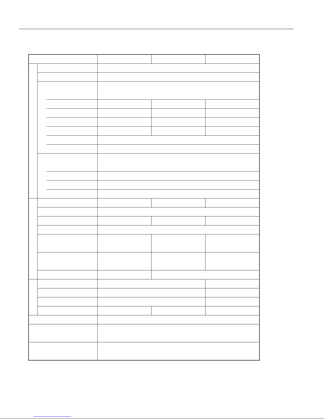
1. SPECIFICATIONS
1-1) SPECIFICATIONS
MODEL
Type
Voltage regulator AVR type
AC Output
Frequency Hz
Rated voltage V
Rated current A
Rated output k
Maximum output kVA
AlternatorEngineDimension
Over current protector
DC Output
Rated voltage V
Rated current A
Over current protector
Model
Type Forced air-cooled,4-cycle,single cylinder OHC type gasoline engine
VA
RG2800DX RG3200DX RG4300DX
2-Pole, Revolving Field type Self Exciting, Single Phase
60
120
EX17 EX27
120/240 120/240
30.8/15.420.0 22.5/11.3
3.72.4 2.7
3.2 4.32.8
1.0Rated power factor
No fuse breaker
12
8.3
100Rated output W
Circuit breaker
EX21
Displacement mL (cu.in.)
Fuel Automotive unleaded gasoline
Fuel tank capacity
L (U.S. gal)
Rated continuous operation
[Approx.] hours
Starting system Recoil starter
Length mm (in.)
Width mm (in.)
Height mm (in.)
Dry weight kg (lb)
Ground system Neutral ground
Valve Clearance
(Intake & Exhaust) mm(in.)
Emissions Durability Period
(California only) hours
Specifications are subject to change without notice.
169 (10.31) 265 (16.17)
10.8 (2.9) 12.8 (3.4)
7.5 6.4
537 (21.1)
432 (17.0)
475 (18.7)
43 (94.8)
0.1±0.03 (0.0039±0.0012)
Note : Adjust the valve clearance while the engine is cold.
211 (12.87)
10.8 (2.9)
6.7
48 (105.8)
500
Recoil / Electric
580 (22.8)
477 (18.8)
508 (20.0)
55 (121.3)
Page 4

– 2 –
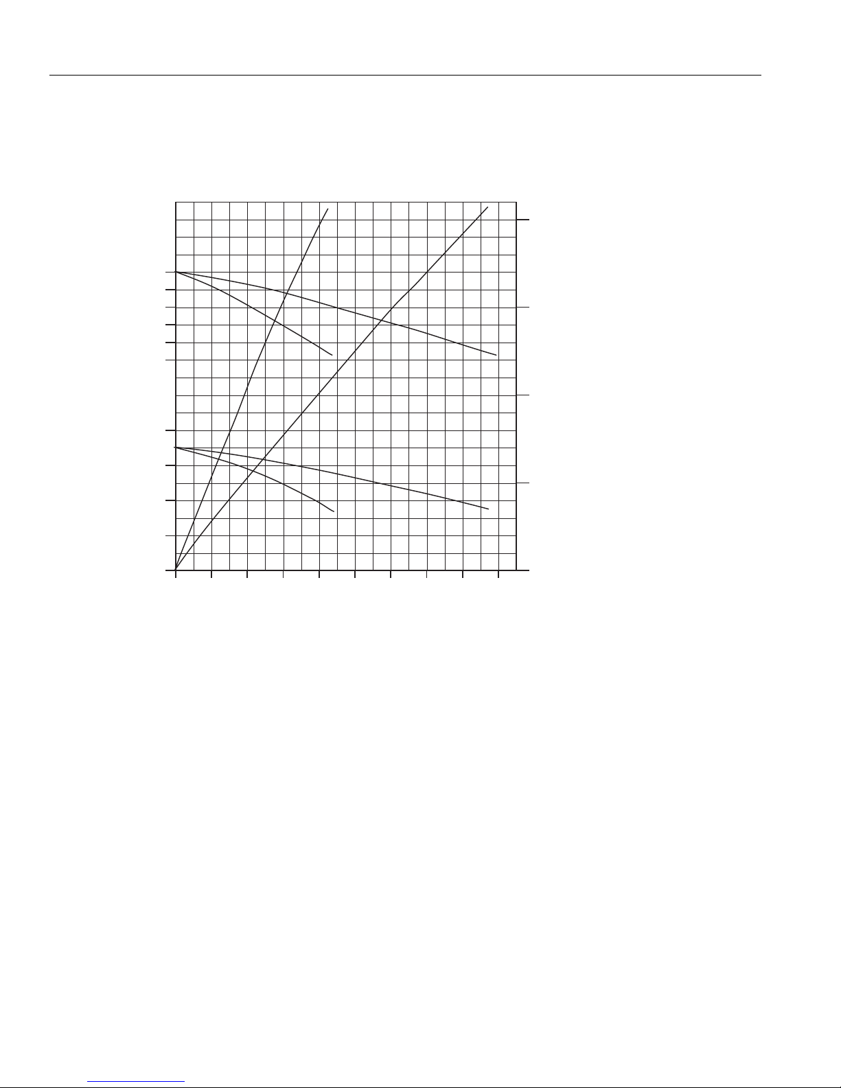
1-2) PERFOMANCE CURVES
RG2800DX [60Hz - 120/240V]
RG3200DX [60Hz - 120/240V]
64
63
(Hz) 62 Rated output 2,400 VA
61
60 2 Frequency 60 Hz
59 Rated voltage 120 V
130 1 (kVA)
(V)
120
110
3
Maximum output 2,800 VA
Rated amperage 20.0 A
0
0 4 8 12 16 20 24
64
63
(Hz) 62 Rated output 2,700 VA
61
60 2 Frequency 60 Hz
59 Rated voltage 120/240 V
130/260 1 (kVA)
(V)
120/240
(A)
3
Maximum output 3,200 VA
Rated amperage 22.5/11.3 A
110/220
0 4 8 12 16 20 24 28
0
(A)
Page 5
– 3 –
RG4300DX [60Hz - 120/240V]
64
63
(Hz) 62 3
61
60
59
130/260
125/250
(V) 1
120/240
115/230
Maximum output 4,300 VA
Rated output 3,700 VA
Frequency 60 Hz
Rated voltage 120/240 V
Rated amperage 30.8/15.4 A
2
(kVA)
0 4 8 12 16 20 24 28 32 36
0
(A)
Page 6
– 4 –
2. GENERAL DESCRIPTION
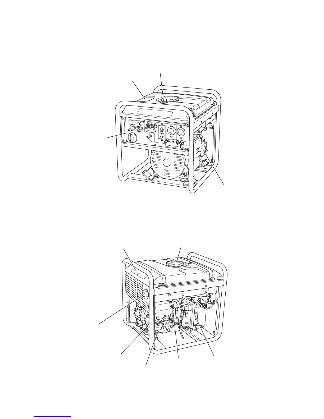
2-1) EXTERNAL VIEW OF GENERATOR
FUEL LEVEL GAUGE
FUEL TANK
CONTROL PANEL
SPECIFICATIONS LABEL
MUFFLER
(EXHAUST OUTLET)
RECOIL STARTER HANDLE
TANK CAP
OIL LEVEL GAUGE
DRAIN PLUG
SPARK PLUG
AIR CLEANER
Page 7
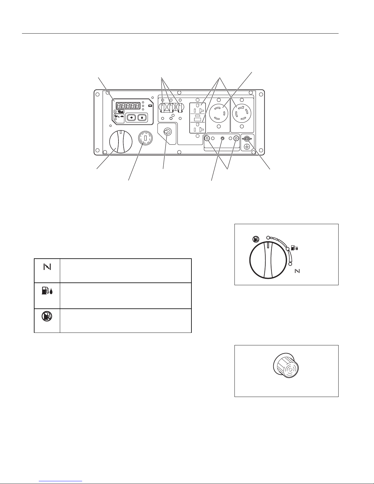
2-2) CONTROL PANEL
– 5 –
(1) ENGINE SWITCH
The engine switch is designed for easy operation with the interlocking
mechanism between the fuel cock and the choke furnished.
(2) PILOT LAMP (Standard model)
The lamp is turned ON (Green) while generating properly.
The lamp will be turned OFF at the same time when the
AC circuit breaker is turned OFF.
CHOKE
To start the engine, turn the knob to the position.
(Choke valve is closed.)
OPEN
Keep the knob in this position after the engine
starts. (The engine can be started with the knob at
this position when the engine is warm.)
CLOSE
To stop the engine, return the knob to the position.
(The fuel cock is closed as well.)
MULTI MONITOR
ENGINE SWITCH
AC CIRCUIT
BREAKER
MULTI MONITOR
AUTO
P-SAVE
Hours
V
Hz
FULL POWER SWITCH
KEY SWITCH
[Electric starter model]
AC RECEPTACLES
DC CIRCUIT
BREAKER
(20A)
DC
TERMINALS
AC RECEPTACLES
(30A)
GROUND
TERMINAL
CLOSE
ENGINE SWITCH
OPEN
CHOKE
PILOT LAMP
Page 8
– 6 –
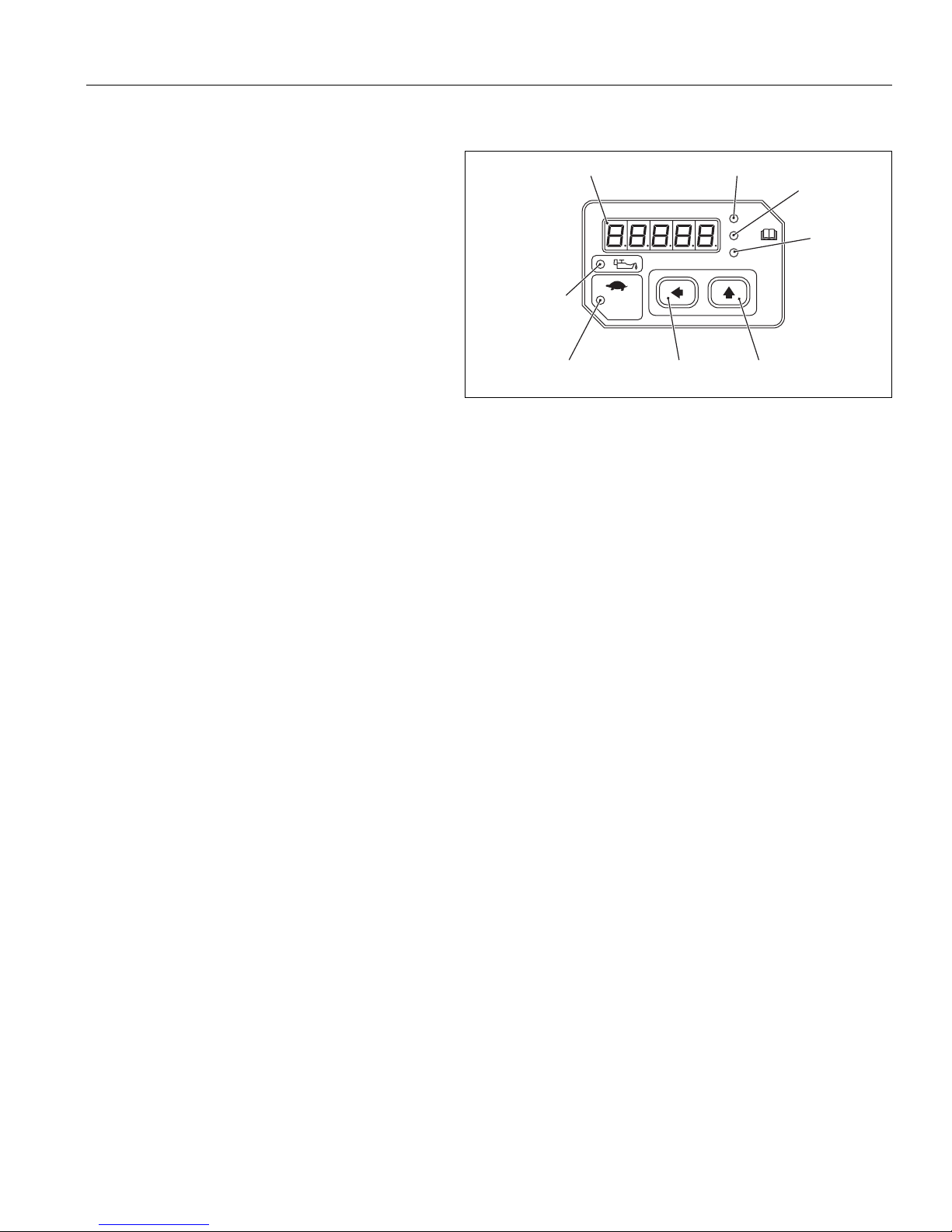
(3) MULTI MONITOR
■■
LE display
Operation hour, voltage and frequency are
indicated in turns by means of depressing the
LE display changeover switch. In addition,
"O_Lod" (overload) will be indicated when the
generator is in the overload condition or
appliance(s) will be out of order.
■■
Operation hour lamp
Lamp (red) is turned on when changing over into operation hour indication in the LE display.
■■
Voltage lamp
Lamp (red) is turned on when changing over into voltage indication in the LE display.
■■
Frequency lamp
Lamp (red) is turned on when changing over into frequency indication in the LE display.
■■
LE display changeover switch
When depressing this switch, indication in LE display is changed over in turns;
operation hour → voltage → frequency → operation hour.
When starting the engine, operation hour is indicated in LE display at first.
■■
Idle switch
When depressing this switch, Idle function is activated.
■■
Idle lamp
Lamp (green) is turned on while Idle function is activated.
■■
Engine oil level warning lamp
When the engine oil level is lower than the specified level, the lamp is turned on.
Then engine will be stopped.
LE display Operation hour lamp
MULTI MONITOR
Engine oil level
warning lamp
IDLE
Auto-power
saving lamp
Auto-power
saving switch
Voltage lamp
Hours
V
Hz
LE display
changeover switch
Frequency
lamp
Page 9
– 7 –
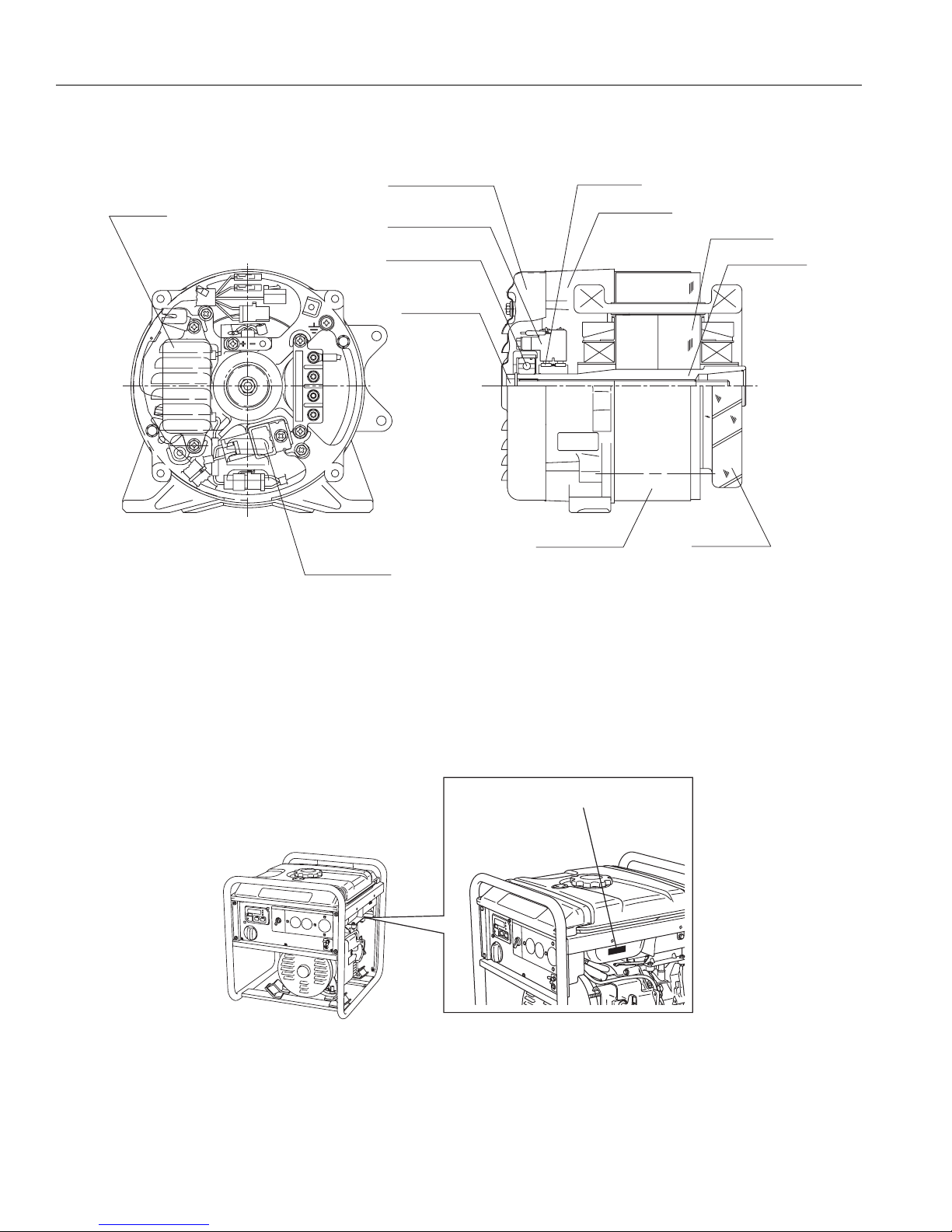
2-4) LOCATION OF SERIAL NUMBER AND PRODUCTION NUMBER
Generator serial number and production number are stamped on the label stuck on the side of fuel tank.
For soundproof type models, remove the side cover (R) to check these numbers.
NOTE : When inquiring about your generator or ordering spare parts, always give us the Model, Serial
Number and Production Number.
2-3) ALTERNATOR
AVR AY
Diode stack
End cover
Brush CP
Ball bearing
Rotor bolt
Slip ring
Rear cover
Stator cover
Rotor CP
Rotor shaft
Stator CP
PROD No. / SER No. (Label)
Page 10

– 8 –
3. RANGE OF APPLICATIONS
Generally, the power rating of an electrical appliance indicates the amount of work that can be done by it.
The electric power required for operating an electrical appliance is not always equal to the output wattage
of the appliance. The electrical appliances generally have a label showing their rated voltage, frequency,
and power consumption (input wattage). The power consumption of an electrical appliance is the power
necessary for using it. When using a generator for operating an electrical appliance, the power factor and
starting wattage must be taken into consideration.
In order to determine the right size generator, it is necessary to add the total wattage of all appliances to
be connected to the unit.
Refer to the followings to calculate the power consumption of each appliance or equipment by its type.
(1) Incandescent lamp, heater, etc. with a power factor of 1.0
Total power consumption must be equal to or less than the rated output of the generator.
Example : A rated 3000W generator can turn thirty 100W incandescent lamps on.
(2)
Fluorescent lamps, motor driven tools, light electrical appliances, etc. with a smaller power factor
Select a generator with a rated output equivalent to 1.2 to 2 times of the power consumption of the
load. Generally the starting wattage of motor driven tools and light electrical appliances are 1.2 to 3
times lager than their running wattage.
Example : A rated 250 W electric drill requires a 400 W generator to start it.
NOTE 1: If a power factor correction capacitor is not applied to the fluorescent lamp, the more power
shall be required to drive the lamps.
NOTE 2: Nominal wattage of the fluorscent lamp generally indicates the output wattage of the lamp.
Therefore, if the fluorescent lamp has no special indication as to the power consumption,
efficiency should be taken into account as explained in ltem (5) on the following page.
(3) Mercury lamps with a smaller power factor
Loads for mercury lamps require 2 to 3 times the indicated wattage during start-up.
Example : A 400 W mercury lamp requires 800 W to 1200 W power source to be turned on. A rated
3000 W generator can power two or three 400 W mercury lamps.
(4) Initially loaded motor driven appliances such as water pumps, compressors, etc.
These appliances require large starting wattage which is 3 to 5 times of running wattage.
Example : A rated 900 W compressor requires a 4500 W generator to drive it.
NOTE 1: Motor-driven appliances require the aforementioned generator output only at the starting.
Once their motors are started, the appliances consume about 1.2 to 2 times their rated power
consumption so that the excess power generated by the generator can be used for other
electrical appliances.
NOTE 2: Motor-driven appliances mentioned in items (3) and (4) vary in their required motor starting
power depending on the kind of motor and start-up load. If it is difficult to determine the
optimum generator capacity, select a generator with a larger capacity.
Page 11
– 9 –
(5) Appliances without any indication as to power consumption
Some appliances have no indication as to power consumption; but instead the work load (output) is
indicated. In such a case, power consumption is to be worked out according to the numerical formula
mentioned below.
Efficiencies of some electrical appliances are as follows :
Single-phase motor . . . . . .0.6 to 0.75 (The smaller the motor, the lower the efficiency)
Fluorescent lamp . . . . . . . .0.7 to 0.8
Example 1: A 40W fluorescent lamp means that its luminous output is 40W. Its efficiency is 0.7 and
accordingly, power consumption will be 40÷0.7= 57W. As explained in Item (2), multiply this
power consumption value of 57W by 1.2 to 2 and you will get the figure of the necessary
capacity of a generator. In other words, a generator with a rated output of 1000W capacity
can light nine to fourteen 40W fluorescent lamps.
Example 2
: Generally speaking, a 400W motor means that its work load is 400W. Efficiency of this motor
is 0.7 and power consumption will be 400÷0.7= 570W. When this motor is used for a
motor-driven tool, the capacity of the generator should be multipled by 1.2 to 3 and 570W as
explained in the ltem (3). 570 (W) x 1.2 to 3 = 684 (W) to 1710 (W)
(Output of electrical appliance)
(Efficiency)
= (Power consumption)
Applications
Applicable Wattage (approx. W)
RG4300DX
3300 / 3700
1700 / 1900
RG2800DX RG3200DX
1600 / 1600
50Hz / 60Hz
700 / 800
Incandescent lamp, Heater, etc 2100 / 2400 2400 / 2700
Fluorescent lamp, Electric tool, etc 1100 / 1200 1200 / 1400
Mercury lamp, etc 800 / 800 1000 / 1000
Pump, Compressor, etc 450 / 500 500 / 550
Page 12

– 10 –
NOTES : Wiring between generator and electrical appliances
1. Allowable current of cable
Use a cable with an allowable current that is higher than the rated input current of the load (electrical
appliance). If the input current is higher than the allowable current of the cable used, the cable will
become excessively heated and deteriorate the insulation, possibly burning it out. The table below
shows cables and their allowable currents for your reference.
2. Cable length
If a long cable is used, a voltage drop occurs due to the increased resistance in the conductors
decreasing the input voltage to the load (electrical product). As a result, the load can be damaged.
The table below shows voltage drops per 30 meters of cable.
2
Allowable
Current
Cable
Resistance
Ω/100m
1.486
0.952
0.517
0.332
1
100
Voltage drops per 30 meters of cable
R : Resistance (Ω/100m)
Cross
sectional
Voltage drop indicates as V= x R x I x L
I : Electric current (A)
L : Length (m)
The length of wire (L) indicates round length, which is the length from the generator
to the electrical tools and back.
<Example> R : Resistance 1.25mm
2
=1.48Ω/100m
I : Electric current 10A
L : Length 30m
The voltage drop of the case described above is
30A25A20A15A10A5AAmm
****8.9V4.5V121.25
***8.6V5.7V2.8V172.0
**6.2V4.7V3.1V1.6V233.5
6.0V5.0V4.0V3.0V2.0V1.0V355.5
1.48Ωx 10A x (30m x 2)
V=
100
≒ 8.9 (V)
Page 13
– 11 –
4. MEASURING AND CHECKING PROCEDURES
4-1) MEASURING INSTRUMENTS
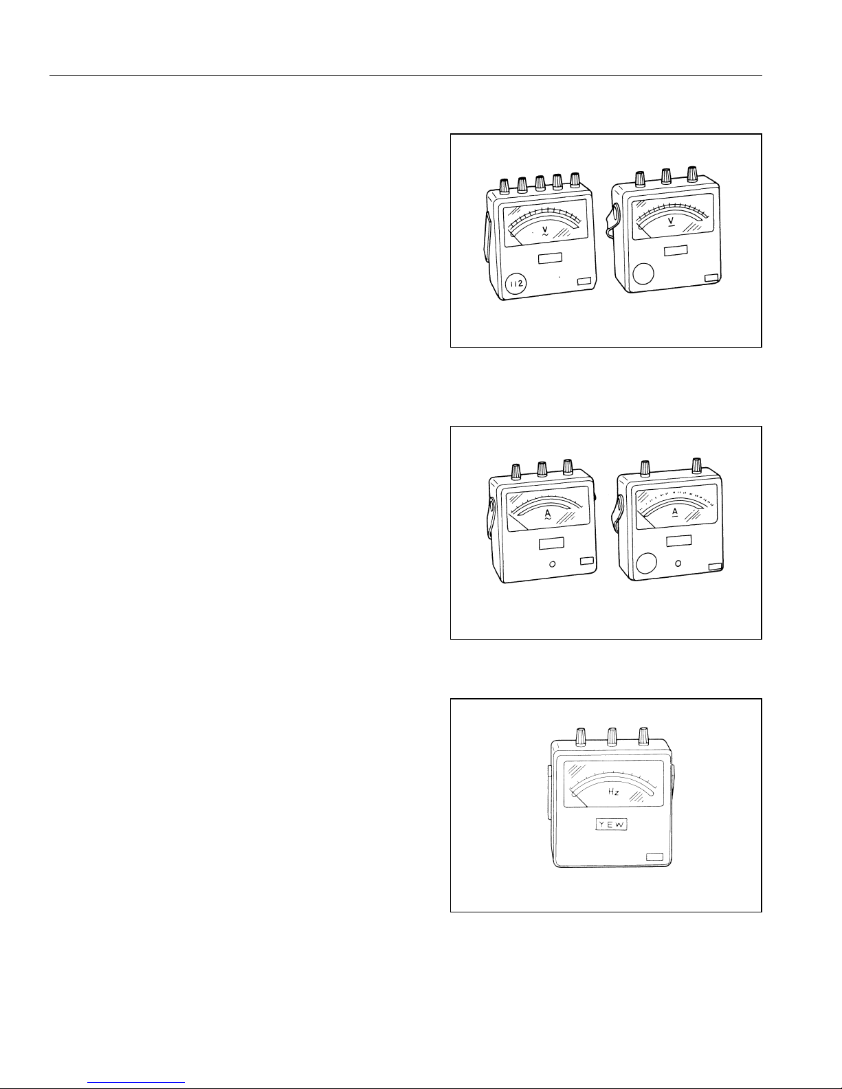
(1) VOLTMETER
AC voltmeter is necessary.
The approximate AC voltage ranges of the
voltmeters to be used for various types of
generators are as follows :
0 to 150 V : Type with an output voltage of 110 or
120 V
0 to 300 V : Type with an output voltage of 220,
230 or 240 V
0 to 150 V, 0 to 330 V : Dual voltage type
(2) AMMETER
AC ammeter is necessary.
An AC ammeter with a range that can be changed
according to the current rating of a given generator
is most desirable. (About 10 A, 20 A, 100 A)
(3) FREQUENCY METER
Frequency range : To cover 45 to 65Hz
NOTE : Be careful of the frequency meter's input voltage
range.
For AC
For AC
For DC
For DC
Page 14
– 12 –
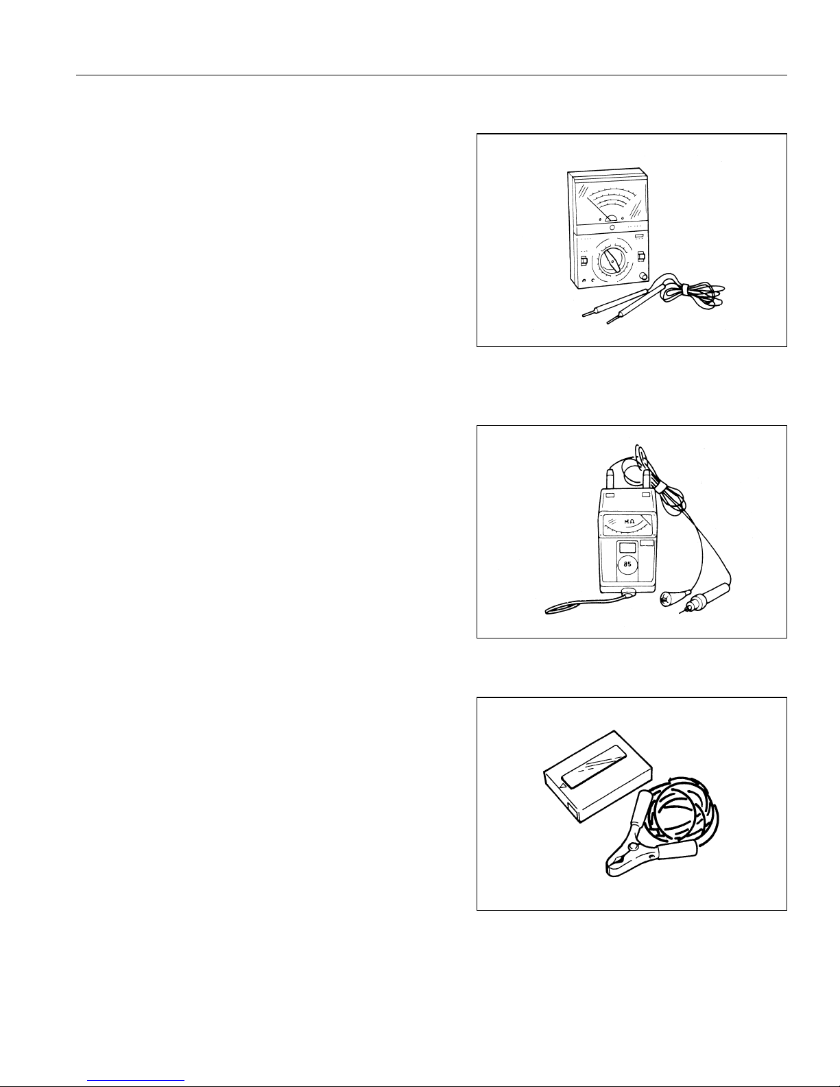
(5) MEAGER TESTER
Used for measuring generator insulation resistance.
Select the one with testing voltage range of 500V.
(4) CIRCUIT TESTER
For measuring resistance, etc.
NOTE : The ordinary circuit tester may cause erroneous
readings due to their measuring method.
Use a high-grade, precise circuit tester to check
the generator components.
(6) TACHOMETER
Use the contactless type tacho meter for checking
engine speed.
Page 15
– 13 –
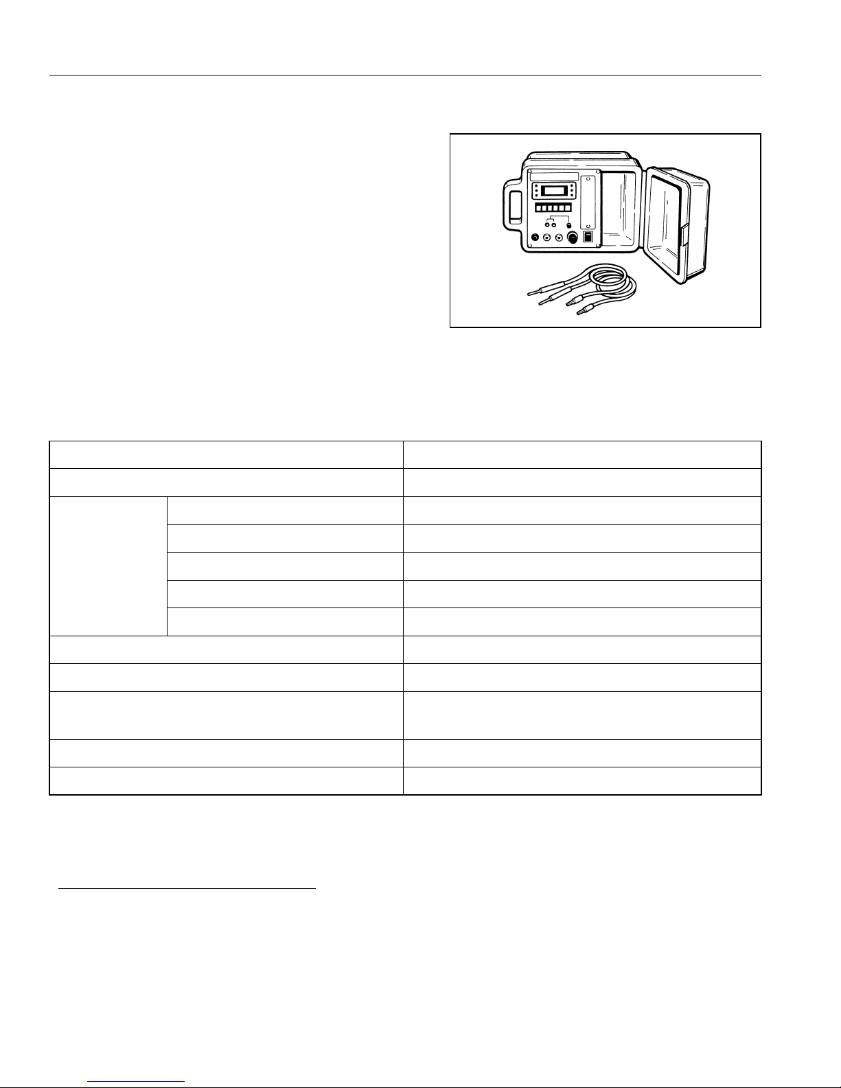
(7) "Dr.Robin" GENERATOR TESTER
The "Dr.Robin" generator tester is exclusively
designed for fast, easy diagnosis and repair of
Robin generators.
The "Dr.Robin" has the following features :
1) Functions of voltmeter, frequency meter, megger
tester, capacitance meter and circuit tester are
combined in one unit.
2) Fast and easy readout by digital indicator.
3) Built-in automatic battery checker indicates the
time to change batteries.
4) Tester and accessories are installed in a handy,
sturdy case for easy carrying.
•
SPECIFICATIONS
MODEL Dr.Robin
Part Number 388-47565-08
Measuring
Range
0 to 500 V AC
25 to 70 Hz
0.1 to 1,999 Ω
10 to 100 μF
3MΩ
Circuit Protector Fuse
Power Source 2 x 6F44P (006P) Dry Cell Battery
Accessories
Test leads with needle probes ... 1 set
Test leads with jack plugs ... 1 set
Dimensions (L x W x H) 285 mm x 200 mm x 110 mm
Weight 1.6 kg
Voltage
Frequency
Resistance
Condenser Capacity
Insulation Resistance
The "Dr.Robin" generator tester can be ordered from Robin generator distributors by the following part number.
Dr.Robin_Part_Number_:_388-47565-08
If you do not have a "Dr.Robin" generator tester, use the instruments described in the following section for
checking generator parts.
Page 16
– 14 –
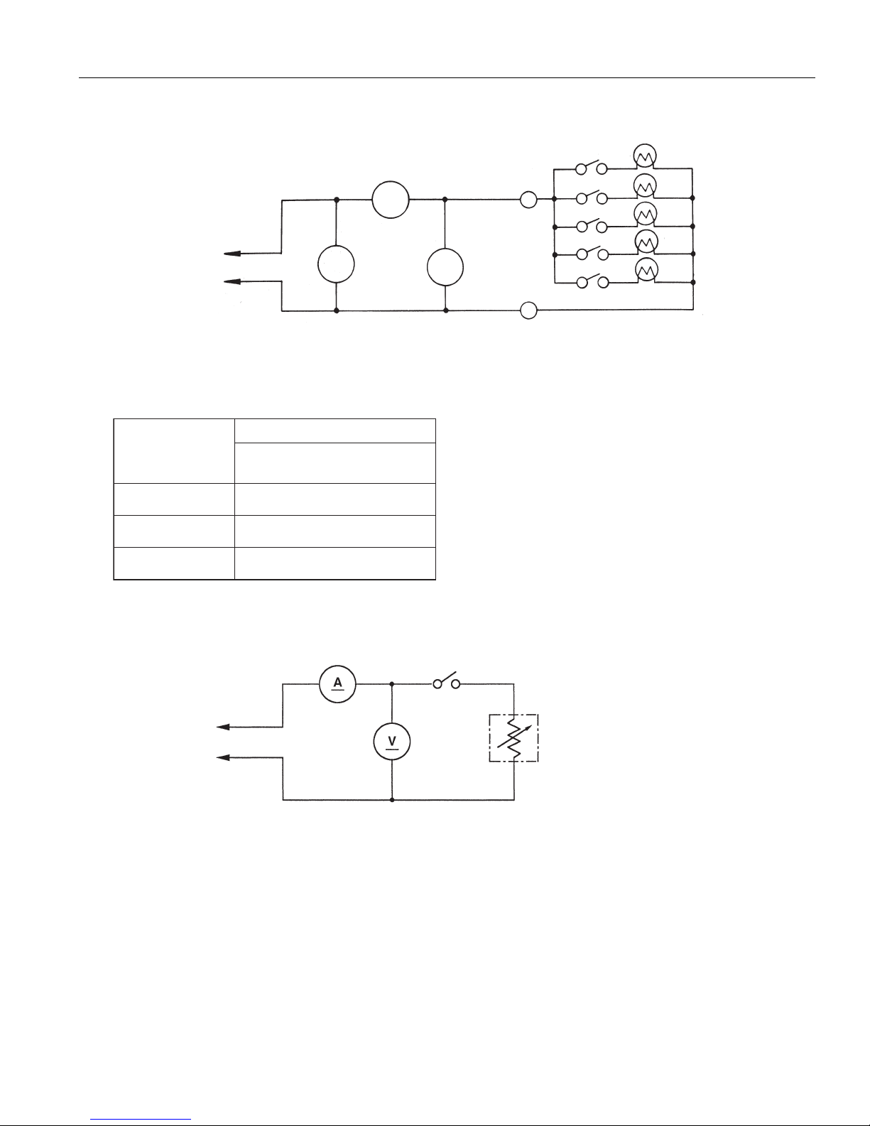
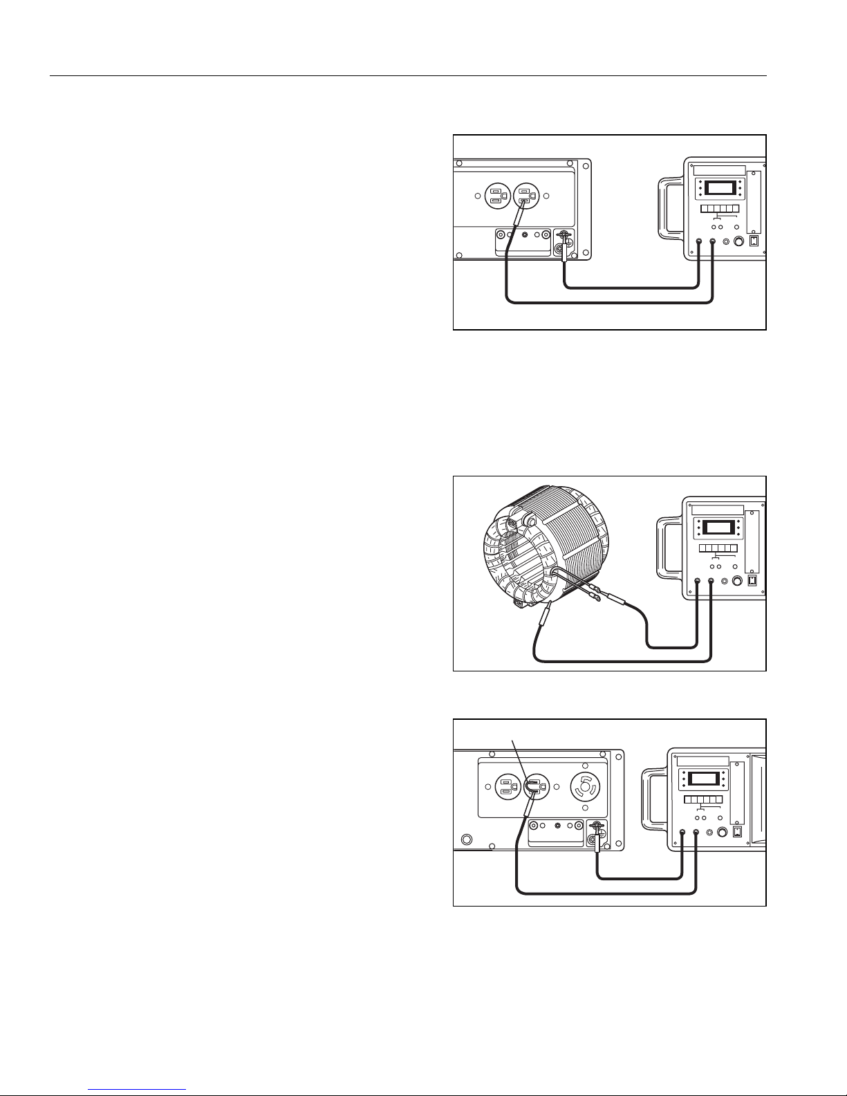
4-2) AC OUTPUT MEASURING
Use a circuit above for measuring AC output. A hot plate or lamp with a power factor of 1.0 may be used as a
load. Adjust the load and rpm, and check that the voltage range is as specified in the following table at the
rated amperage and rated rpm.
4-3) DC OUTPUT MEASURING
Measurement of DC output is executed with the switch turned ON while the current is regulated at 8.3A by
adjusting the load to the generator. If the voltage is within the range from 6V to 14V, the voltage output is
normal.
NOTE : If a battery is connected as a load to the generator, the DC output voltage will increase by
approximately 1 to 2 V.
Therefore, carefully observe the electrolyte level and do not overcharge the battery.
TO AC RECEPTACLE
SWITCH
A
~
F
V
~
LOAD
Specification
Model
60Hz-120V
60Hz-120/240V
RG2800DX
RG3200DX
119 - 133
240 - 269
RG4300DX
237 - 265
SW
To DC Terminal
Load
Page 17
– 15 –
4-4) MEASURING INSULATION RESISTANCE
Use a “Dr. Robin” generator tester in megger tester
mode or use a megger tester to check the insulation
resistance. Connect a megger tester to one of
receptacle output terminals and the ground terminal,
then measure the insulation resistance. An insulation
resistance of 1 megohm or more is normal. (The original
insulation resistance at the time of shipment from the
factory is 10 megohm or more.) If it is less than 1
megohm, disassemble the generator and measure the
insulation resistance of the stator, rotor and control
panel individually.
●
STATOR
Measure insulation resistance between each terminal
from the stator and the stator core.
Measured insulation resistance of 1M ohm or
more is normal.
If it is less than 1M ohm, leakage current and
electric shock might occur due to faulty insulation.
Replace with new one.
●
CONTROL PANEL
With AC circuit breaker turned on, measure insulation
resistance between each portion of electrical parts
and earth (grounding) terminal or control panel itself.
Measured insulation resistance of 1M ohm or
more is normal.
If it is less than 1M ohm, leakage current and electric
shock might occur due to faulty insulation.
Replace with new one.
Any part where the insulation resistance is less than
1MΩ has faulty insulation, and may cause electric
leakage and electric shock.
Replace the faulty part.
Wire
Page 18
– 16 –
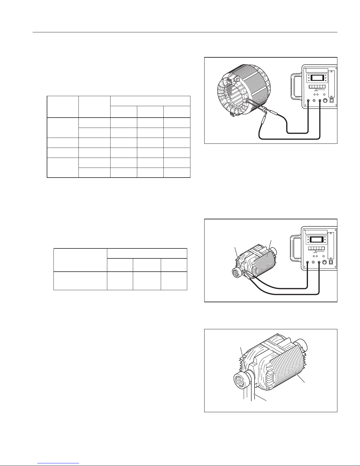
4-5) CHECKING FUNCTIONAL MEMBERS
(1) STATOR
Disengage connectors on the wires from stator and check
the resistance between the wires using a circuit tester
referring to the table below.
NOTE :
If the circuit tester is not sufficiently accurate, it may not show the values given and may give erroneous readings.
Erroneous readings will also occur when there is a wide variation of resistance among coil windings or
when measurement is performed at ambient temperature different from 20°C (68°F).
(2) ROTOR ASSEMBLY
1) Field coil
Measure resistance between the slip rings.
2) Cleaning Slip rings
The slip ring surfaces must be uniformly bright.
Slip rings showing black spots, excessive wear, or
uneven wear must be repaired.
A stained slip ring lowers generator efficiency and
output voltage.
Polish the slip rings with fine sandpaper while turning
the rotor until rough spots disappear.
NOTE :
When measuring, tolerance should be considered
because of the tester inaccuracy, winding number
variation, ambient temperature etc.
NOTE : Care should be taken not to touch the rotor
coils with the sandpaper.
Coil resistance (Ω)
Main coil
Exciter coil
DC coil
Sub coil
Wire color
Black−Yellow
Green−Red
Blue−Blue
Brown−Brown
Yellow−Yellow
Black−Black
RG2800DX RG4300DXRG3200DX
0.7
-
1.3
0.6
0.4 0.4
0.3 0.3 0.3
Coil resistance (Ω)
RG2800DX RG4300DXRG3200DX
Field coil
(Between two Slip rings)
41 4744
0.9
0.9 0.5
1.2
0.5
0.5
1.1
0.4
0.3
Rotor
Slip ring
Slip ring
Rotor
Sandpaper
Page 19

– 17 –
(3)BRUSH
The brushes must be smooth where they contact the slip
rings. If not, polish smooth the brushes with sandpaper.
A brush that is not smooth produces arcs between the
brush and slip ring leading to possible damage.
A brush shorter than 5 mm must be replaced because
decreased contact pressure between the brush and slip
ring lowers generator efficiency and output voltage.
(4)AC CIRCUIT BREAKER
Check continuity between each of two terminals at the
rear of the AC circuit breaker while it is mounted on the
control panel.
(5) DC CIRCUIT BREAKER
Check that there is continuity between the two terminals
of DC circuit breaker when its push button is pressed.
AC circuit breaker
OFF
:No continuity
BRUSH HOLDER
5 mm
BRUSH
ON :Continuity
Page 20

– 18 –
(6) A.V.R (AUTOMATIC VOLTAGE REGULATOR)
1) Features
This AVR operates to control the field current in
order to maintain the output voltage for the AC
current, which generated by the magnetic flux by
the field coil.
2) A.V.R. trouble may be identified by simply looking
at the A.V.R., or by the inter-lead resistance with
a tester, or actually mounting it in the generator
and operating it.
(a) A.V.R. TROUBLE IDENTIFICATION by APPEARANCE
If an A.V.R. electronic part is burnt dark, or the surface epoxy resin melted, it often indicates A.V.R.
trouble.
(b) IDENTIFYING A.V.R. TROUBLE by CHECKING INTER-LEAD RESISTANCE
Check the inter-lead resistance of the A.V.R. with a tester, referring to the following table.
If the tester readings very greatly from the values specified in the table, the A.V.R. is faulty.
(c) IDENTIFYING A.V.R. TROUBLE by MOUNTING and OPERATING in THE GENERATOR
SCR or transistor damage cannot be detected by simply looking at the A.V.R. or checking the lead
resistance. Check it by mounting the suspectedly faulty A.V.R. in a normal generator, or mount a normal
A.V.R. in a generator which fails to generate voltage.
Apply black (minus) needle
Apply red (plus)
needle of the
circuit tester
Orange/Green
of the circuit tester
Orange/Green
−
ContinuityOrange
Orange
No continuity
−
4P Connector
Red-White
Blue
:No continuity
-
Blue:No continuity
Page 21

– 19 –
(9) FLOAT TYPE OIL SENSOR
Check the oil sensor when it is installed on the engine.
Check that sufficient engine oil is filled in the crankcase.
Check that there is continuity between the lead wire of
oil sensor and the ground (engine crankcase) when the
oil level is above the minimum level mark of oil gauge.
Check that there is no continuity as above when the oil
level is below the minimum level mark of oil gauge.
(8) AC RECEPTACLES
Check that no live part or wire or plastic part is burnt.
(7) DIODE RECTIFIER
The circuit inside the diode rectifiers is as shown in the chart
above.
Check continuity between each terminal by using a circuit
tester.
The rectifier is normal when continuity is as follows:
Brown
Brown
1
2
3
Orange
Checking table for analogue circuit tester
Analogue circuit tester
Apply black (minus) needle of the circuit tester
123
2
1
3
Apply red (plus)
of the circuit tester
needle
1
-
No continuity2
Continuity3
Checking table for digital circuit tester
Digital circuit tester
Apply black (minus) needle
of the circuit tester
Apply red (plus)
1
No continuity2
Continuity3
123
-
No continuity
-
Continuity
needle of the circuit tester
No continuity
-
Continuity
No continuity
No continuity
-
No continuity
No continuity
-
Oil sensor
Page 22

– 20 –
5. DISASSEMBLY AND ASSEMBLY
5-1) PREPARATION AND PRECAUTIONS
(1) Be sure to memorize the location of individual parts when disassembling the generator so that the generator
can be reassembled correctly. Tag the disassembled part with the necessary information to facilitate easier and
smoother reassembly.
(2) For more convenience, divide the parts into several groups and store them in boxes.
(3) To prevent bolts and nuts from being misplaced or installed incorrectly, replace them temporarily to their
original position.
(4) Handle disassembled parts with care; clean them before reassembly using a neutral cleaning fluid.
(5) Remove the battery before disassembling the generator. (Electric start models)
(6) Use all disassembly/assembly tools properly, and use the proper tool for each specific job.
(7) Be sure to attach the foam rubber linings inside the covers on their original position when reassembling the
generator. When deformation or damage or falling-off of foam rubber lining is found, replace it with new part.
Failure to do so will result in poor performance and durability of the generator.
(8) Bind the wires and fuel pipes using wire bands as they have been done in original configuration.
NOTE : As to detailed information for servicing procedures on engine portion, please refer to Robin engine service
manual for models EX13/17/21/27.
5-2) SPECIAL TOOLS
Use correct tools to prevent unnecessary effort and giving damages to the parts.
Part Number
33B9990801
Part Name Shape Usage
FLYWHELL HOLDER33B9990101
DRIVESHAFT HOLDER33B9990201
ROTOR PULLER
Page 23

– 21 –
(3) Remove fuel strainer.
5-3) DISASSEMBLY PROCEDURES
5-3-1
FUEL PIPES, FUEL STRAINER and BATTERY CABLES
(1) Turn the engine switch to “STOP” position to close
fuel cock.
(2) Disconnect fuel pipes from fuel strainer.
5-3-2 REAR COVER
(1) Remove muffler cover.
M6 x 18mm Flange bolt :6pcs.
Tools : 10mm Box wrench
(2) Remove upper rear cover.
Fuel strainer
Muffler cover
(Rear)
Rear cover
(Upper )
Page 24

– 22 –
5-3-3 AUTOTHROTTLE COUPLER [Deluxe model]
Disengage the coupler from the auto-throttle unit of carburetor.
5-3-4 CHOKE WIRE [Deluxe model]
Loosen screw fixing choke wire to carburetor choke lever.
Turn the engine switch to “CHOKE” position to disconnect
choke wire from choke lever.
Tools : Screw driver
5-3-5 GROUNDING WIRE
Remove grounding wire at the right bottom side of control
panel.
M6 Nut :1pce.
Auto-throttle
coupler
Choke wire
Grounding wire
Page 25

– 23 –
5-3-6 END COVER
Remove end cover.
M5 x 10mm bolt : 2pcs.
Tools : Screw driver
5-3-7 FRONT COVER (UPPER)
BRACKET (COVER)
Remove front cover (upper).
For disassembling the front cover (upper), see
illustrations on the following page.
Disconnect alternator couplers.
End cover
Page 26

– 24 –
FRONT COVER (UPPER) and CONTROL PANEL
Gromet
Front cover (Upper)
Multi
monitor
Micro
switch
AC circuit
breaker
AC receptacles
DC circuit
breaker
Engine switch
CONTROL PANEL
AC receptacles
Ground
terminal
DC
terminals
4.0 - 6.0 N・m
40 - 60 kgf・cm
(3.0 - 4.4 ft・lbs)
M6 Screw
Page 27

– 25 –
5-3-9 WIRE BAND
Cut the wire band binding wires behind control panel.
For electric starter model, cut the wire band binding battery
cables also.
Tools : Nipper
5-3-8 BRUSH HOLDER
(1) Remove brush holder.
M5 x 18mm Screw : 1pce.
Tools : Screw driver
5-3-10 FUEL TANK
Loosen bolts and remove fuel tank from frame.
M6 x 20mm Flange reamer bolt :4pcs.
Rubber :4pcs.
Tools : 10mm Box wrench
NOTE1 : Be sure to drain fuel from the tank before
removing the tank.
NOTE2 : Take care not to get lost the four mounting
rubbers of the tank.
Brush holder
Wire band
Fuel tank
Page 28

– 26 –
FUEL TANK and FUEL LINE
Fuel gauge
Fuel tank cap
Fuel filter
4.0 - 6.0 N・m
40 - 60 kgf・cm
(3.0 - 4.4 ft・lbs)
Fuel tank
M6 Flange
reamer bolt
Rubber pipe
Fuel strainer
Screw
Filter
O-ring
Cup
Rubber pipe
Rubber
(Tank)
Page 29

– 27 –
5-3-13 MUFFLER
(1) Loosen nuts and remove muffler.
M8 Flange nut : 2 pcs.
Tools : 12mm Box wrench
(2) Loosen bolts and remove muffler bracket.
M6 x 23mm Flange bolt : 2pcs.
Tools : 10mm Box wrench
5-3-11 FOAM RUBBER INSULATORS
Remove foam rubber insulators from the gaps between
frame and fuel tank.
5-3-12 MUFFLER COVER
Loosen bolts and remove muffler cover (L) by pushing it
inward.
M6 x 12mm Flange bolt : 4pcs.
Tools :10mm Box wrench
Page 30

– 28 –
5-3-14 GOVERNOR ROD [Standard model only]
Take out governor rod from carburetor throttle shaft.
5-3-15 ROD SPRING [Standard model only]
Take out rod spring from carburetor throttle shaft.
Tools : Long-nose pliers
5-3-16 GOVERNOR LEVER [Standard model only]
Remove governor lever.
M6 x 25mm Bolt and Washer : 1pce.
Tools : 10mm Box wrench
Plier
Throttle shaft
Rod spring
Throttle shaft
Governor rod
Governor lever
Page 31

– 29 –
5-3-17 AIR CLEANER and CARBURETOR
(1) Remove air cleaner cover and element from the air
cleaner.
(2) Loosen nuts and a bolt, and remove air cleaner body.
M6 Flange nut : 2pcs.
M6 x 20mm Flange bolt : 1pce.
Tools : 10mm Box wrench
(3) Be sure not to break the gasket, carefully remove
carburetor from insulator.
Element
Cleaner cover
Air cleaner base
Carburetor
Page 32

– 30 –
5-3-18 ENGINE BLOCK
(1) Loosen nuts fixing the engine to mount rubbers, and
remove the engine.
M8 Flange nut : 4pcs.
Tools : 12mm Box wrench
(2) Remove mount rubbers from frame as necessary.
M8 Flange nut : 4pcs.
Tools : 12mm Box wrench
5-3-19 CRANKSHAFT COVER
Loosen bolts and remove crankshaft cover.
M8 x 12 Flange bolt : 2pcs.
Tools : 12mm Box wrench
5-3-20 REAR COVER
Remove rear cover along with stator.
Cover
(Crankshaft)
Page 33

– 31 –
ALTERNATOR
Rotor Puller
Remove rotor by using the Rotor Puller.
Special tools : Rotor Puller (33B9990801)
5-3-21 ROTOR BOLT and ROTOR
(1) Remove rotor bolt.
Rotor bolt : 1pce.
Tools : Socket wrench
NOTE : Since the thread of the through bolt is in
reverse direction, turn it clockwise to
loosen.
End cover
Grommet
AVR unit
M5 Bolt
2.0 - 3.4 N・m
20 - 34 kgf・cm
(1.4 - 2.5 ft・lbs)
Brush holder
6.5 - 8.5 N・m
65 - 85 kgf・cm
(4.7 - 6.1 ft・lbs)
Rotor Bolt
Rear cover
Bearing
Washer
19.0 - 21.0 N・m
190 - 210 kgf・cm
(13.7 - 15.2 ft・lbs)
Rotor
Stator cover
Stator
Bolt
(M6)
Stator
M5 Bolt
8.0 - 10.0 N・m
80 - 100 kgf・cm
(5.8 - 7.2 ft・lbs)
Page 34

– 32 –
5-3-22 RECOIL STARTER
Loosen bolts and remove recoil starter.
M6 x 18mm Flange bolt : 3pcs.
Tools : 10mm Box wrench
NOTE : Refer to section 5-5 for further instruction for
disassembly/reassembly procedures of recoil
starter.
5-3-23 BOTTOM EXTENSION PLATE
Loosen bolts and remove bottom extension plate.
M8 x 33mm Flange bolt for crankcase side : 2 pcs.
M8 x 12mm Flange bolt for blower housing side : 2 pcs.
Tools : 12mm Box wrench
5-3-24 BLOWER HOUSING
Loosen bolts and remove blower housing.
M6 x 35mm Bolt : 1pce.
M6 x 45mm Bolt : 3pcs.
Tools : 10mm Box wrench
Recoil starter
Bottom extension plate
Blower housing
M6x35mm Bolt
M6x45mm
Bolt
Page 35

– 33 –
5-3-25 DRIVE SHAFT and FAN
Using the special tool “DRIVE SHAFT HOLDER” to hold
drive shaft, loosen bolts to remove drive shaft and fan
from the flywheel.
M8 x 27mm Flange bolt : 4pcs.
Tools : 12mm Box wrench
Drive shaft holder (33B9990201)
5-3-26 FLYWHEEL
Using the special tool “FLYWHEEL HOLDER” to hold
flywheel, loosen flywheel nut.
Remove flywheel using an ordinary flywheel puller.
M19 Nut : 1pce.
Tools : Socket wrench
Flywheel Holder (33B9990101)
Flywheel puller (Available on market)
Drive shaft
Drive shaft holder
Flywheel holder
Page 36

– 34 –
5-4) REASSEMBLY PROCEDURES
NOTE : The mount rubbers are designed to isolate the
vibration most effectively by their original stiffness
and shape of rubber. Be sure to use the correct
mount rubbers attaching them to the correct position.
5-4-1 MOUNT RUBBERS
Attach the four Mount Rubbers to the frame. Insert the
locating tab of mount rubber into the locating hole of the
frame and fix it by tightening M8 flange nut.
M8 Flange nut : 4pcs.
5-4-2 FLYWHEEL
NOTE : Be sure to wipe off oil from the tapered portion
of the crankshaft and the hole of flywheel
before assembly.
Install the Flywheel onto the crankshaft and tighten the
Flywheel Nut using the special tool “FLYWHEEL
HOLDER” to hold the flywheel.
M19 Nut : 1pce. (EX17, 21)
Tightening torque : 59.0-64.0 N・m
590
-
640 kgf
・
cm
(43.5
-
47.2 ft・lbs)
Tightening torque : 10.0
-
12.0 N
・
m
100
-
120 kgf・cm
(7.4
-
8.7 ft・lbs)
5-4-3 FLYWHEEL FAN and DRIVE SHAFT
(1) Install the Flywheel Fan to the flywheel so as that the
three alignment tabs on the back of flywheel fan to
mate with the holes of the flywheel.
(2) Assemble the Drive Shaft onto the flywheel.
Tighten the four M8 bolts while holding the drive shaft
using the special tool “Drive Shaft Holder”.
M8 x 27mm Flange bolt : 4pcs.
Tightening torque : 25.0-27.0 N・m
250
-
270 kgf・cm
(18.4
-
19.9 ft・lbs)
Top side of frame
Drive shaft
Drive shaft holder
Page 37

– 35 –
5-4-4 BLOWER HOUSING
(1) Assemble the Blower Housing onto the crankcase.
M6 x 35mm Bolt : 1 pce.
M6 x 45mm Bolt : 3 pcs.
Tightening torque : 8.0
-
10.0 N
・
m
80
-
100 kgf
・
cm
(5.9
-
7.4 ft
・
lbs)
Tightening torque : 18.0-22.0 N・m
180
-
220 kgf・cm
(13.3
-
16.2 ft・lbs)
5-4-5 BOTTOM EXTENSION PLATE
Assemble the Bottom Extension Plate to the engine.
M8 x 33mm Flange bolt for crankcase side : 2 pcs.
M8 x 12mm Flange bolt for blower housing side : 2 pcs.
Tightening torque : 6.5-8.5 N・m
65
-
85 kgf・cm
(4.8
-
6.3 ft・lbs)
5-4-6 RECOIL STARTER
Assemble the Recoil Starter to blower housing.
M6 x 18mm Bolt : 3pcs.
NOTE : Refer to section 5-5 for further instruction for
disassembly/reassembly procedures of recoil
starter.
Blower housing
M6x35mm Bolt
M6x45mm
Bolt
Bottom extension plate
Recoil starter
Page 38

– 36 –
5-4-8 REAR COVER
Assemble the Rear Cover to the blower housing.
M6 x 90mm Stator Bolt : 4pcs.
Tightening torque : 6.5
-
8.5 N
・
m
65
-
85 kgf
・
cm
(4.8
-
6.3 ft
・
lbs)
5-4-7
THROUGH BOLT (thread in reverse direction)
Insert the Rotor bolt into the center of rotor shaft and
tighten it.
Rotor bolt : 1 pce.
Tightening torque : 19.0
-
21.0 N
・
m
190
-
210 kgf
・
cm
(14.0
-
15.5 ft
・
lbs)
NOTE1 : Wipe off oil, grease and dust from the tapered
portion of engine shaft and matching tapered
hole of rotor shaft.
NOTE2 : The thread of the Through Bolt is in reverse
direction.
Therefore, torque it counter-clockwise to
tighten it.
5-4-9 COVER (CRANKSHAFT)
Assemble the Cover (Crankshaft) to the main bearing
cover.
M8 x 12mm Flange bolt : 2 pcs.
Tightening torque : 18.0-22.0 N・m
180
-
220 kgf・cm
(13.3
-
16.2 ft・lbs)
Cover
(Crankshaft)
Page 39

– 37 –
NOTE : The nut on the LH-side rear cover commonly
fixes grounding wire.
5-4-10 Installation of ENGINE and ALTERNATOR
ASSEMBLY onto FRAME
Install the engine and alternator assembly onto frame
carefully aligning the bolts of mounting rubbers into the
engine/alternator base.
Then tighten flange nuts.
M8 Flange nut : 4pcs.
5-4-11 CARBURETOR
Install the Carburetor to the intake flange.
NOTE: Be sure to attach the gasket between the
carburetor and the intake flange.
5-4-12 AIR CLEANER BASE
Attach the Air Cleaner Base to the carburetor and fix with
two M6 bolts and one M6 Flange bolt.
M6 Flange nut : 2 pcs.
M6 x 20mm Flange bolt : 1 pce.
Tightening torque : 6.0
-
8.0 N
・
m
60
-
80 kgf
・
cm
(4.4
-
5.9 ft
・
lbs)
Tightening torque : 10.0-12.0 N・m
100
-
120 kgf・cm
(7.4
-
8.7 ft・lbs)
Air cleaner base
Carburetor
Page 40

– 38 –
5-4-13 AIR CLEANER ELEMENT
Assemble the Air Cleaner Element and the Air Cleaner
Cover to the air cleaner base.
Wash the cleaner element if it is dirty before reassembly.
5-4-15 ROD SPRING [Standard model only]
Fit Rod Spring onto Carburetor Throttle Shaft.
5-4-14 GOVERNOR LEVER [Standard model only]
Fix Governor Lever with the Governor Shaft fully turned
clockwise.
M6 x 25mm Bolt and Washer : 1pce.
Element
Cleaner cover
Governor lever
Rod spring
Throttle shaft
Page 41

– 39 –
5-4-17 MUFFLER
Install Muffler to the engine.
M8 Flange nut : 2 pcs.
M6 x 23mm Flange bolt : 2 pcs.
Tightening torque : 4.0-6.0 N・m
40
-
60 kgf・cm
(3.0
-
4.4 ft・lbs)
Tightening torque : 17.0-19.0 N・m
170
-
190 kgf・cm
(12.5
-
14.0 ft・lbs)
5-4-16 GOVERNOR ROD
[Standard model only]
Install Governor Rod onto Carburetor Throttle Shaft.
Throttle shaft
Governor rod
Page 42

– 40 –
Tightening torque : 4.0-6.0 N・m
40
-
60 kgf・cm
(3.0
-
4.4 ft・lbs)
5-4-18 MUFFLER COVER
Attach the Muffler Cover to the muffler.
M6 x 12mm Flange bolt : 4 pcs.
5-4-19 SPONGE
Install the Sponges between the fuel tank and the frame
as shown in the figure righrt.
5-4-20 FRONT COVER (UPPER)
Temporarily fit Front Cover (upper) in position.
Connect alternator couplers.
5-4-21 BRUSH HOLDER
Install the brush holders in the rear cover.
M5 x 18mm Screw : 1pce.
Brush holder
Page 43

– 41 –
5-4-22 GROUNDING WIRES
Fasten the grounding wire from the alternator.
Tools : Screw driver
5-4-23 Connection of WIRING HARNESS
Connect engine wire harness couples.
Connect main coil wiring to the terminal; Red wiring to
the upper terminal, while White to the lower one.
Connect couples of wiring harness between control
panel and alternator.
Main coil wiring
Page 44

– 42 –
5-4-25 FUEL TANK
(1) Install the Fuel Tank onto the frame. Be sure to insert
the mount rubbers between the tank and the frame.
M6 x 20mm Flange bolt : 4 pcs.
Mount Rubbers : 4 pcs.
5-4-26 Clamping of CHOKE CABLE and
GROUNDING WIRES
Clamp the choke cable and grounding wires using a wire
band.
(2) Attach two pieces of Rubber Seal (Tank).
(3) Attach the Sponge Seal (Muffler).
Tightening torque : 4.0
-
6.0 N
・
m
40
-
60 kgf・cm
(3.0
-
4.4 ft・lbs)
5-4-24 AUTO THROTTLE
(1) Connect the wires to Auto Throttle Unit of the
carburetor.
(2) Temporarily connect the choke cable to the
carburetor choke lever.
Auto-throttle
coupler
Fuel tank
Wire band
Page 45

– 43 –
5-4-27 REAR COVER (UPPER) and
MUFFLER COVER (REAR)
(1) Attach the Rear Cover (Upper) first to the frame.
(2) Install the Muffler Cover (Rear) onto the Rear Cover
(Upper) and the frame.
M6 x 18mm Flange bolt : 6pcs.
Tightening torque : 4.0-6.0 N・m
40
-
60 kgf・cm
(3.0
-
4.4 ft・lbs)
5-4-28 END COVER
Attach the End Cover to the rear cover.
M5 x 10mm bolt : 2pcs.
Rear cover
(Upper )
Muffler cover
(Rear)
End cover
Page 46

– 44 –
Tightening torque : 4.0-6.0 N・m
40
-
60 kgf・cm
(3.0
-
4.4 ft・lbs)
5-4-29 FRONT COVER (UPPER)
Securely fix Front Cover (upper).
M6 x 12mm Flange bolt : 4 pcs.
5-4-30 CHOKE WIRE
Fix the Choke Wire to the carburetor choke lever making
sure that the choke valve is fully closed when engine
switch is turned to “CHOKE” position.
NOTE : Be sure to install the return spring.
5-4-31 GROUNDING WIRE
Fasten the grounding wire to the frame.
M6 Screw : 1pce.
Front Cover (Upper)
Choke wire
Grounding wire
Page 47

– 45 –
(2) Connect the fuel pipe from carburetor to the Fuel
Strainer. Clamp the fuel pipe with a hose clamp.
5-4-32 FUEL STRAINER and FUEL PIPE
(1) Align the shaft of engine switch to the Fuel Strainer
Cock when the engine switch is in “STOP” position
and the fuel cock closed.
Fuel strainer
Page 48

– 46 –
5-5) RECOIL STARTER
Tools used : Long-nose pliers, retaining-ring pliers, protective goggles
The recoil starter of this device is located between the alternator assembly and the engine, so remove the recoil
starter after removing the alternator assembly.
Caution :
Please wear protective goggles before starting disassembly
Caution :
The pull of the spring is maximized while the rope is fully pulled out.
Please do not release it suddenly, or relax your grip.
1) Disassembly procedures
(1) Unhook the spring.
-1 Hold the starter handle, and pull out the starter
rope.
-2 Pull out all of the rope, and align the rope guide
and the knot of the rope inside the reel.
-3 Be sure to hold the reel with both thumbs
so your fingers do not become be entangled.
-4 Pull the knot of the rope out from the reel, loosen
the knot, then pull it up from the starter handle
side (this should be done by two people).
-5 Slowly rewind the rope until the reel stops while
controlling the reel with both thumbs.
Starter rope
Starter handle
Page 49

– 47 –
Caution :
The reel is disassembled with the spring still
assembled, so place it on a flat table without
dropping, or shaking.
(2) Remove the small parts.
-1 Hold the case, and remove the retaining-ring C
with the ring pliers.
-2 Beginning at the top, remove the retaining-ring,
friction plate, and ratchet.
Disassembly is completed.
(3) Remove the reel.
-1 Move the reel to left and right at a 1/4 turns
several times until it moves smoothly, gently
holding it down.
-2 Slowly lift the reel, removing it from the case.
-3 Repeat (3) 1 and (3) 2 if the spring assembled in
the reel sticks out.
Retaining-ring
pliers
Retaining-ring C
Retaining-ring C
Ratchet
Friction
spring
Reel
Friction plate
Starter handle
Spiral spring
Starter case
Page 50

– 48 –
(2) Install the ratchet and friction spring.
Install the ratchet and friction spring into the reel.
(3)Installation of friction plate and retaining ring C.
Install by putting the Tab of friction plate into the
hole of the ratchet.
Fasten with the retaining ring C.
Be sure that the retaining ring is fitted into the
grooves.
Caution:
Please wear protective goggles before starting assembly.
2) Assembly procedure
(1) Assemble the reel into the case.
-1 Apply grease to the case.
-2 Properly orient the inner end of the spring installed
in the reel.
-3 Hold the reel so that the shaft and hook part can
be caught on the inner end of the spring, and
softly drop into the case from the top.
-4 Move the reel gently in the counter-clockwise
direction, making sure that the spring catches.
Hooking
position
Inner end of
the spring
Grease
Reel
Spiral
spring
Starter case
Retaining-ring C
Friction plate
Ratchet
Friction
spring
Friction plate
Retaining-ring C
Page 51

– 49 –
(4) Wind the spiral spring.
-1 Holding the case, turn the reel five turns in
counter-clockwise.
-2 Fix the reel in the position that the rope hole of
reel aligns with the rope guide.
(5) Inserting the rope.
(this should be done by two people)
-1 Thread the rope end through the rope guide and
the rope hole of the reel, and pull 20cm out from
the reel.
-2 Tight the end of the rope.
-3 Fix the rope end to the reel.
-4 Hold the rope at the distance 50cm from the rope
guide. Hold securely.
-5 Gently release the reel and have it wind the rope
on the reel until the knot reaches the rope guide.
Caution:
Do not release the pressure to hold the reel
while winding the spiral spring.
The spring force is strong and cause sudden
rewinding if you release the pressure.
Assembly is completed.
※These are the disassembly and assembly procedures, please be sure to review the following item checklist to
insure that the parts securely installed.
Five turns in counter-clockwise
About 20cm
About 10mm
Page 52

– 50 –
3) Checking items after assembly
(1) Try to pull the starter handle for 2 to 3 times.
(a)When the starter handle is difficult to pull, please make sure the parts, etc., are installed in the right direction.
(b)When the ratchet does not operate, please re-check if there are any missing parts such as the spring.
(2) Pull the starter handle and try to pull the starter rope out to the limit.
(a)When the starter rope does not return smoothly, or the starter handle is hangs down loosely, please add
grease or mobile oil in the rotating and friction parts.
If it still does not work, rewind 1~2 times.
(In that case, confirm that the spring is not under pressure by following the previous procedure.)
(b)Please re-assemble from the beginning if there was the sound when the spring was removed and the starter
rope does not re-winded into the reel.
4) When . . .
(1)The spring pops out
(a)Hook the end hook of the spring to the notched
part of the reel, and attach the spring, applying
pressure with your fingers so that it isn’t released
from the groove. (Please wear gloves)
(b)Hook the inside hook of the spring to the claw of
the starter case while turning.
※ Please refer to assembly procedures.
(2) Oil refill
At the end of the season or when disassembling, add
grease (preferably one that is heat resistant, if
possible) or mobile oil to rotation parts, friction parts,
and the spring.
ReelSpiral spring
Page 53

– 51 –
6.TROUBLE SHOOTING
Check if engine speed is normal.
50Hz : 3,000rpm
60Hz : 3,600rpm
OK
Check if brush is weared.
Check if the total length of
brush is 5mm or over.
OK
Check if stator coil is normal.
Main coil
Exciter coil
NG
NG
NG
Refer to
"Engine dose not start (Start failure )"
Check and replace brush.
Replace
OK
Check if rotor coil is normal.
OK
Check if AVR is normal.
OK
Check if wiring is break or
improper connection.
NG
NG
NG
Replace
Replace
Replace when wiring is break or damage.
Connect properly.
Page 54

– 52 –
No DC current
Check if DC coil of stator is normal.
OK
Check if diode rectifier is normal.
OK
Check if DC circuit breaker is normal.
OK
NG
NG
NG
Replace
Replace
Replace
Check if wiring is break or
improper connection.
NG
Replace when wiring is break or damage.
Connect properly.
Page 55

– 53 –
Improper revolutions (Electronic throttle)
Engine starts but
stops suddenly.
No
・Engine revolution
does not increase.
・Hunting
・Pull the recoil starter lightly with the full throttle open.
Full throttle direction :Throttle direction is from the air cleaner in front
towards opposite direction (towards the back)
Go to the engine malfunction section.
engine check (refer to p. 00)
Yes
Yes
Go to the start malfunction section
Confirm connection of
electronic throttle coupler.
Confirmed
Does
not run
Change the carburetor
Runs
・Dirty or bad spark plug
・Poor return of the choke
・Air cleaner blockage
・Muffler blockage
・Bad carburetor (water contamination, blockage, etc.)
・Lack of gasoline
・Gasoline deterioration
・Blockage from the tank to the carburetor
Page 56

– 54 –
Engine does not start (Start failure)
Check the gasoline
in the tank
Yes
Oil warning lamp turns on
when the recoil is pulled
Fuel cock is in
the ON position
Yes
Gasoline leaks when the
carburetor drain is loosened
Yes
Check for
gasoline deterioration
Good
Remove the spark plug
and check the electrode
Wet
Attach the plug to the plug
cap, and check for sparks
by pulling the recoil starter
None
warning
lamp is on
No
Open
the cock
No
Clean,
change
the filter
Deteriorated
Dry
Blockage of the fuel passage or
jets of carburotor
No or
poor sparks
Add gasoline
Check the oil level
Good
Confirm of the oil sensor
E/g
GND
Change
gasoline
・Check for dirty electrodes, or gap
・Check the connection of coupler,
high tension cord and spark plug cap
STANDARD MODEL
DELUXE MODEL : Change the Monitor unit
Low
Resistance
value≒0Ω
Tester
No continuity
: Change the Oil sensor unit
Add oil (up to the
rated volume)
Change Oil sensor
Good Sparks
Check the compression
at the spark plug hole
by pulling recoil starter
Poor compression
Valve clearance adjustment
Page 57

– 55 –
7. WIRING DIAGRAM
RG2800DX (60Hz-120V) [Recoil starter model]
GENERATOR
FC
EXC
Main
coil
DC
winding
Sub coil 1
Sub coil 2
W
Org
Gry
Blk
Blk
Y
Y
AVR
AC Circuit
R
Grn
breaker
RR
Blu
Blu
DC Circuit
breaker
Org Org
Gry
W
Blu
DC output
terminal
Grn/Y
CONTROL PANEL
Grn/Y
Grn/Y
120V
Blu
Blu
R
Brn
Grn/Y
Stepping
motor
Oil level
sensor
ENGINE
Wiring color code
Blk : Black
Blk/W : Black/White
Blu : Blue
Spark
plug
Ignition
coil
Grn
Blu
Pur
Gry
Y
Org
Blk
LBlu : Light blue
Brn : Brown
Brn/W : Brown/White
MONITOR C/U
Grn : Green
Grn/W : Green/White
Org : Orange
Blk
W
Gry : Gray
R : Red
W : White
Engine
switch
Y : Yellow
W/Blk : White/Black
Grn/Y : Green/Yellow
Grn/Y
Grn/Y
Earth (ground)
terminal
Pur : Purple
Pin : Pink
Page 58

– 56 –
RG3200DX/4300DX (60Hz-120/240V) [Recoil starter model]
GENERATOR
FC
EXC
Main
coil 2
Main
coil 1
DC
winding
Sub coil 1
Sub coil 2
W
Org
Gry
Blk
Blk
Y
Y
AVR
R
AC Circuit
R
Grn
Y
Blk
breaker
RRR
Blu
W
Blk Blk
DC Circuit
breaker
Org Org
Gry
W
Blu
AC Circuit
breaker
120/240V
1
2
3
4
5
6
Blu
120V
W
Blk
Blk
DC output
terminal
Grn/Y
CONTROL PANEL
Grn/Y
Grn/Y
W
120V
Brn
R
Blu
120V
11
8
R
7
9
10
12
120/240V
Grn/Y
Blu
R
W
Blu
Blu
Stepping
motor
Oil level
sensor
ENGINE
Wiring color code
Blk : Black
Blk/W : Black/White
Blu : Blue
Spark
plug
Ignition
coil
Grn
Blu
Pur
Gry
Y
Org
Blk
LBlu : Light blue
Brn : Brown
Brn/W : Brown/White
MONITOR C/U
Grn : Green
Grn/W : Green/White
Org : Orange
Blk
W
Gry : Gray
R : Red
W : White
Grn/Y
Engine
switch
Y : Yellow
W/Blk : White/Black
Grn/Y : Green/Yellow
Grn/Y
Earth (ground)
terminal
Pur : Purple
Pin : Pink
Page 59

– 57 –
RG3200DX/4300DX (60Hz-120 / 240V) [Electric starter model]
GENERATOR
FC
EXC
Main
coil 2
Main
coil 1
DC
winding
Sub coil 1
Sub coil 2
W
Org
Gry
Blk
Blk
Y
Y
AVR
R
AC Circuit
R
Grn
Y
Blk
breaker
RRR
Blu
W
Blk Blk
DC Circuit
breaker
Org Org
Gry
Brn
Brn
AC Circuit
breaker
120/240V
1
2
3
4
5
6
Y
Y
Blu
120V
W
Blk
Blk
DC output
terminal
Regulator
W
Blu
Grn/Y
R
120V
Brn
Grn/Y
Grn/Y
AC Circuit
breaker
Grn/Y
R
CONTROL PANEL
R
7
8
9
10
11
W
Blu
120V
W
12
W
120/240V
Blu
Grn/Y
Blu
R
Blu
Stepping
motor
Oil level
sensor
Starting
motor
M
ENGINE
Wiring color code
Blk : Black
Blk/W : Black/White
Blu : Blue
Spark
plug
Battery
Ignition
coil
R
Blk
LBlu : Light blue
Brn : Brown
Brn/W : Brown/White
Grn
Blu
Pur
Gry
Y
Org
Blk
R
W
MONITOR C/U
Engine switch
Fuse10A
Relay
Grn : Green
Grn/W : Green/White
Org : Orange
Grn/Y
Blk
W
Gry : Gray
R : Red
W : White
M-
ST
L.IG
M+
B
Key
switch
Org
R
Grn/Y
Y : Yellow
W/Blk : White/Black
Grn/Y : Green/Yellow
Grn/Y
Earth (ground)
terminal
Pur : Purple
Pin : Pink
Page 60

ISSUE EMD-GS2025
2005.08
 Loading...