

Page 1
6
Generator
Model
16072, LG102,lG152, LGZOl,LG301
LG2OlD,
LG301D
LGK102, LGK152
Page 2
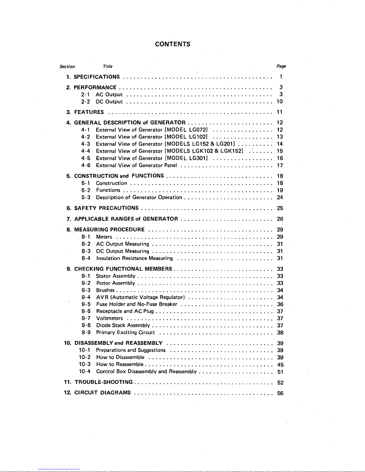
CONTENTS
Section
Title
Page
1 . SPECIFICATIONS
..........................................
1
2
.
PERFORMANCE
............................................
3
2-1 AC Output
.........................................
3
2-2 DCOutput
.........................................
10
3
.
FEATURES
..............................................
11
4 . GENERAL DESCRIPTION
of
GENERATOR
........................
12
4-1 External View
of
Generator [MODEL LG0721
.................
12
4-2 External View
of
Generator [MODEL LG1021
.................
13
4-3 External View
of
Generator [MODELS LG152 & LG2011
..........
14
4-4 External View
of
Generator [MODELS LGK102 & LGK1521
........
15
4-5 External View
of
Generator [MODEL LG3011
.................
16
4-6 External View
of
Generator Panel
..........................
17
5
.
CONSTRUCTION
and
FUNCTIONS
..............................
18
5-1 Construction
........................................
18
5-2 Functions
..........................................
19
5-3 Description
of
Generator Operation
.........................
24
6
.
SAFETY PRECAUTIONS
.....................................
25
7
.
APPLICABLE RANGESof GENERATOR
..........................
26
8.-
MEASURING PROCEDURE
...................................
29
8- 1 Meters
.............................................
29
8-2 AC Output Measuring
..................................
31
8-3 DC Output Measuring
..................................
31
8-4 Insulation Resistance Measuring
...........................
31
9
.
CHECKING FUNCTIONAL MEMBERS
............................
33
9-1 Stator Assembly
......................................
33
9-2 Rotor Assembly
.......................................
33
9-3 Brushes
.............................................
34
9-4 AVR (Automatic Voltage Regulator)
........................
34
9-5 Fuse Holder and No-Fuse Breaker
..........................
36
9-6 Receptacle and AC Plug
.................................
37
9-7 Voltmeters
.........................................
37
9-8 Diode Stack Assembly
..................................
37
9-9 Primary Exciting Circuit
................................
38
10
.
DISASSEMBLY
and
REASSEMBLY
..............................
39
10-1 Preparations and Suggestions
..............................
39
10-2 How to Disassemble
...................................
39
10-3 How to Reassemble
....................................
45
10-4 Control Box Disassembly and Reassembly
......................
51
11 . TROUBLE.SHO0TlNG
.......................................
52
12
.
CIRCUIT DIAGRAMS
.......................................
56
Page 3
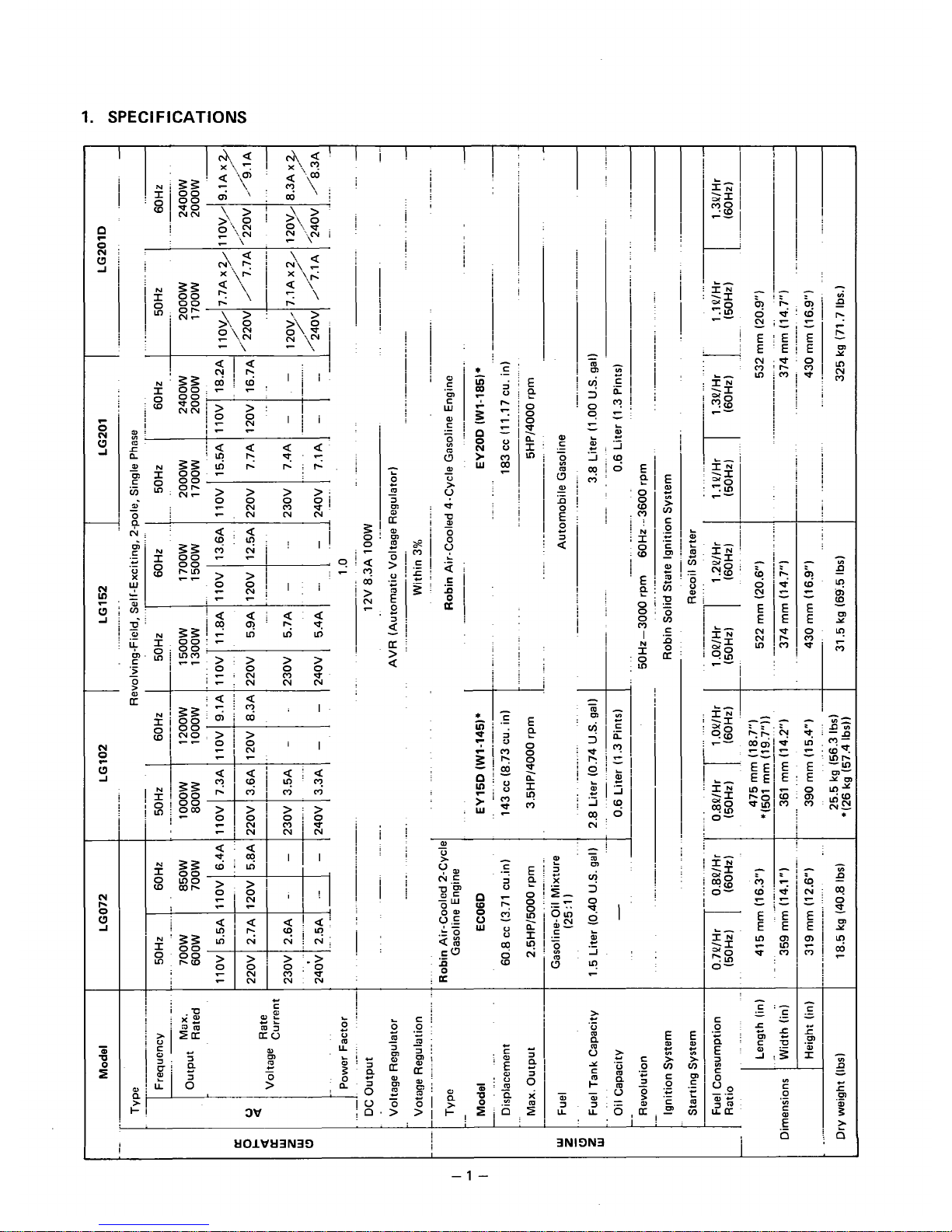
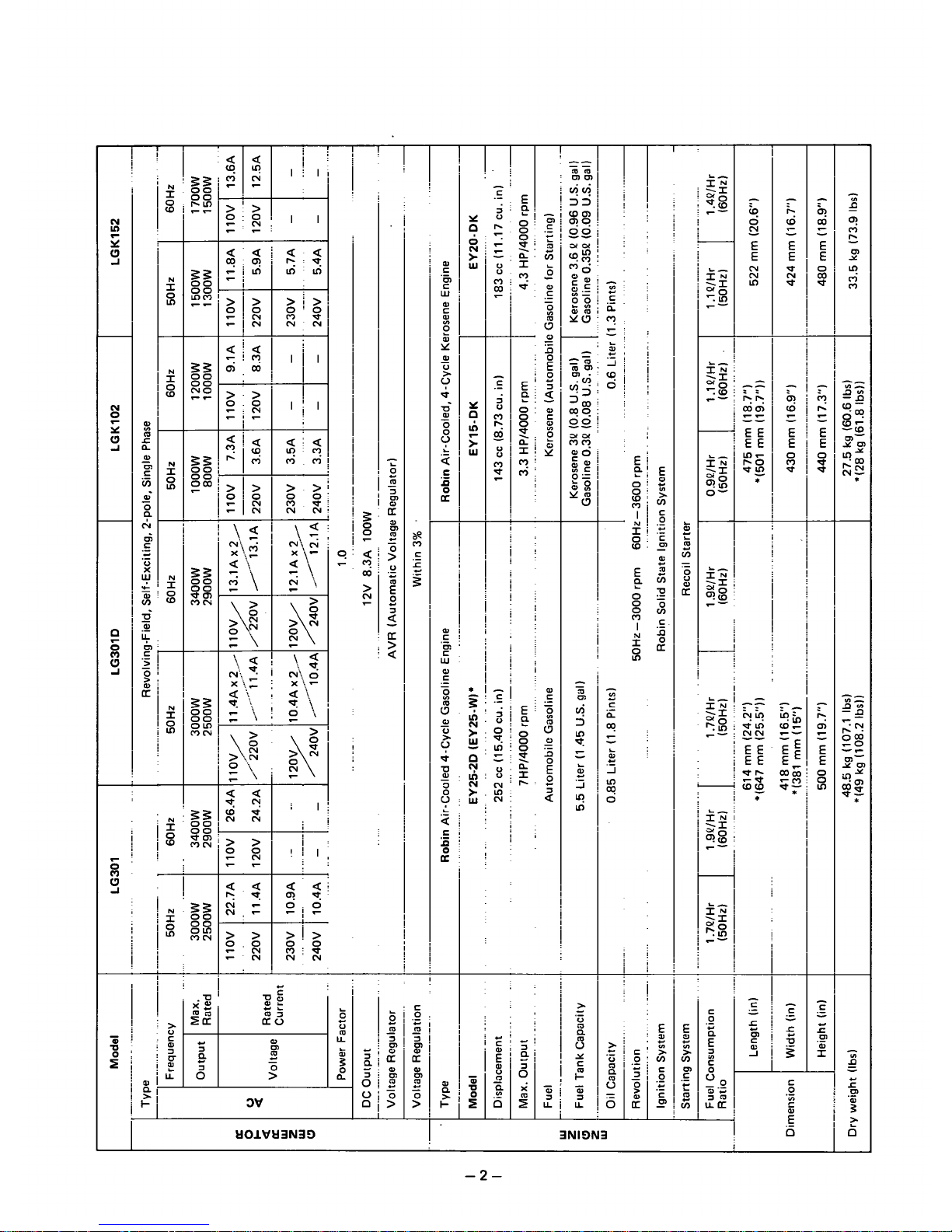
1.
SPECIFICATIONS
T
N
I
0
m
E
P
f
0
0
0
n
I
m
N
I
P
P
-
0
V
-
.-
-
'a
p
9
'I
f
a, a
a
-m
mm
"
a-
Y
:-
I
i
I
-
LT
>
a
I
t
i
I
!
!
1
I
i
I
-
9
0
W
-
E
E
0
0
0
P
n
I
m
m
.
I
i
!
i
!
!
..
.:
I
c
.-
>
3N19N3
t101Vt13N30
I
-1
-
Page 4
-
;9
0
N
-
E
E
N
N
m
-
N
I
54
-
N
I
W
0
-
N
I
5:
-
N
0
I
W
aa
'I.0
rnm
>i>
a00
NN
L
I
9
r
..
.I
!.
..
i:
I.
..
I
i
t
L
L
.-
ai
:i
I
!I
I,
..
..
c
>>
zz
"
T
!
i
>!>
00
mi*
NN
3NION3
I
-2-
Page 5
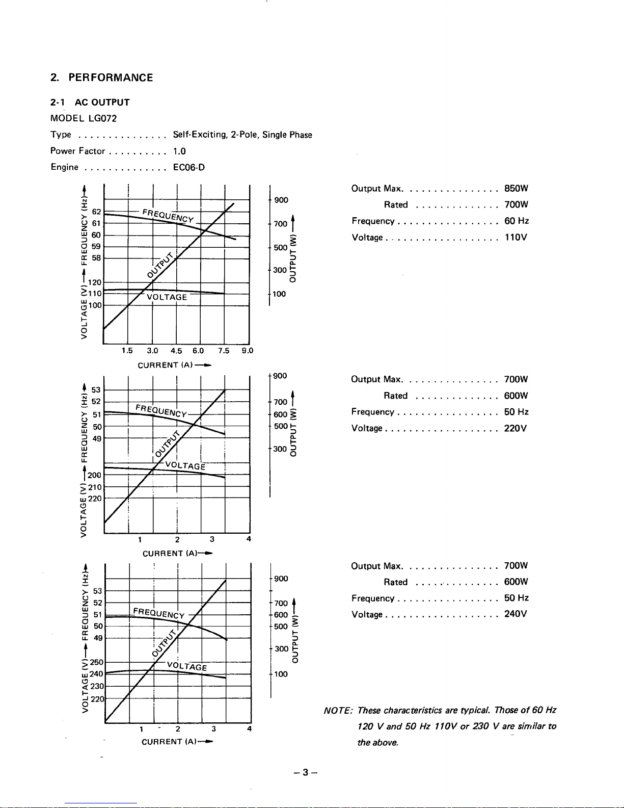
2.
PERFORMANCE
2-1
AC
OUTPUT
MODEL LG072
Type
...............
Self-Exciting, 2-Pole, Single Phase
Power Factor
..........
1.0
Engine
..............
ECOG-D
I
1
N
I
-
62
>
y
61
$60
8
59
58
I
t
1
20
21
10
"
100
a
5
W
0
>
Output Max.
...............
850W
Rated
..............
700W
Frequency.
................
60
HZ
Voltage
.............
....
110v
t
loo
1.5 3.0 4.5 6.0 7.5
9.0
CURRENT
(A)
-
900
Output Max.
...............
700W
-
4
53
..............
-
?
52
t700,
Rated
600W
&
51
600
Frequency.
50
Hz
5
50 500
+
Voltage.
..................
220V
=
49
................
I
2
8
+
U
300
2
LL
1200
-
-
>
210
W
220
0
a
I
5
0
>
1
2 3 4
CURRENT
(A)-
f
Output Max.
...............
700W
2
Rated
...............
600W
1
..
900
I-
u
49
L
-500
-
8
50
Frequency. 50
Hz
-700
1
2
52
>
53
T
300
2
250
0
~240
IlOO
I-
................
W
2
51
"600
-
Voltage.
..................
240V
CT
t
2
-
230
$220
>
NOTE:
These characteristics are typical.
Those
of
60
Hz
1-2 3 4
120
V
and
50
Hz
1
1OV
or
230
V
are similar to
CURRENT
(A)-
the above.
-3-
Page 6
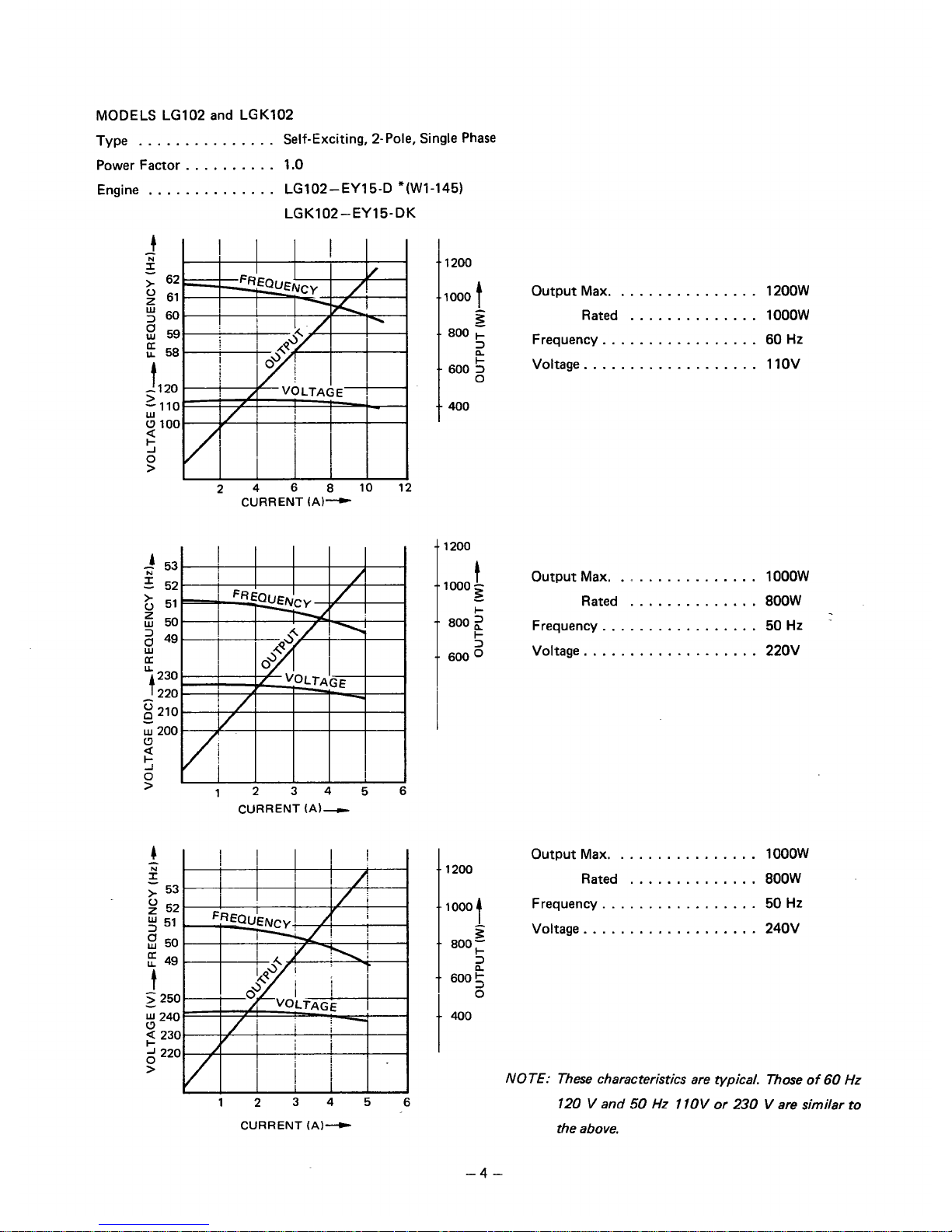
MODELS LG102 and LGK102
Type
...............
Self-Exciting, 2-Pole, Single Phase
Power Factor
..........
1.0
Engine
..............
LG102-EY15-D "(Wl-145)
LGK102-EY15-DK
CURRENT
(A)-
CURRENT
(A)-
123456
CURRENT
(A)-
I
-.
1200
-1000
3
..
800
f
.-
600
3
0
--
400
-.
1200
t
.-
1000
-
+
I-
.-
600
o
3
--
aoo
2
i
I
I
..
1200
..
1000
1
3
..
aoo;
2
t
-.
600
5
Output Max.
...............
12OOW
Rated
..............
1
OOOW
Frequency.
................
60
HZ
Voltage.
..................
110V
Output Max.
...............
1OOOW
Rated
..............
800W
Frequency.
................
50
Hz
Voltage.
..................
220V
Output Max.
...............
1OOOW
Rated
..............
800W
Frequency.
................
50
HZ
Voltage.
..................
240V
NOTE: These characteristics are typical. Those of
60
Hz
120
V
and
50
Hz
1
1OV
or
230
V
are similar to
the above.
-4
-
Page 7
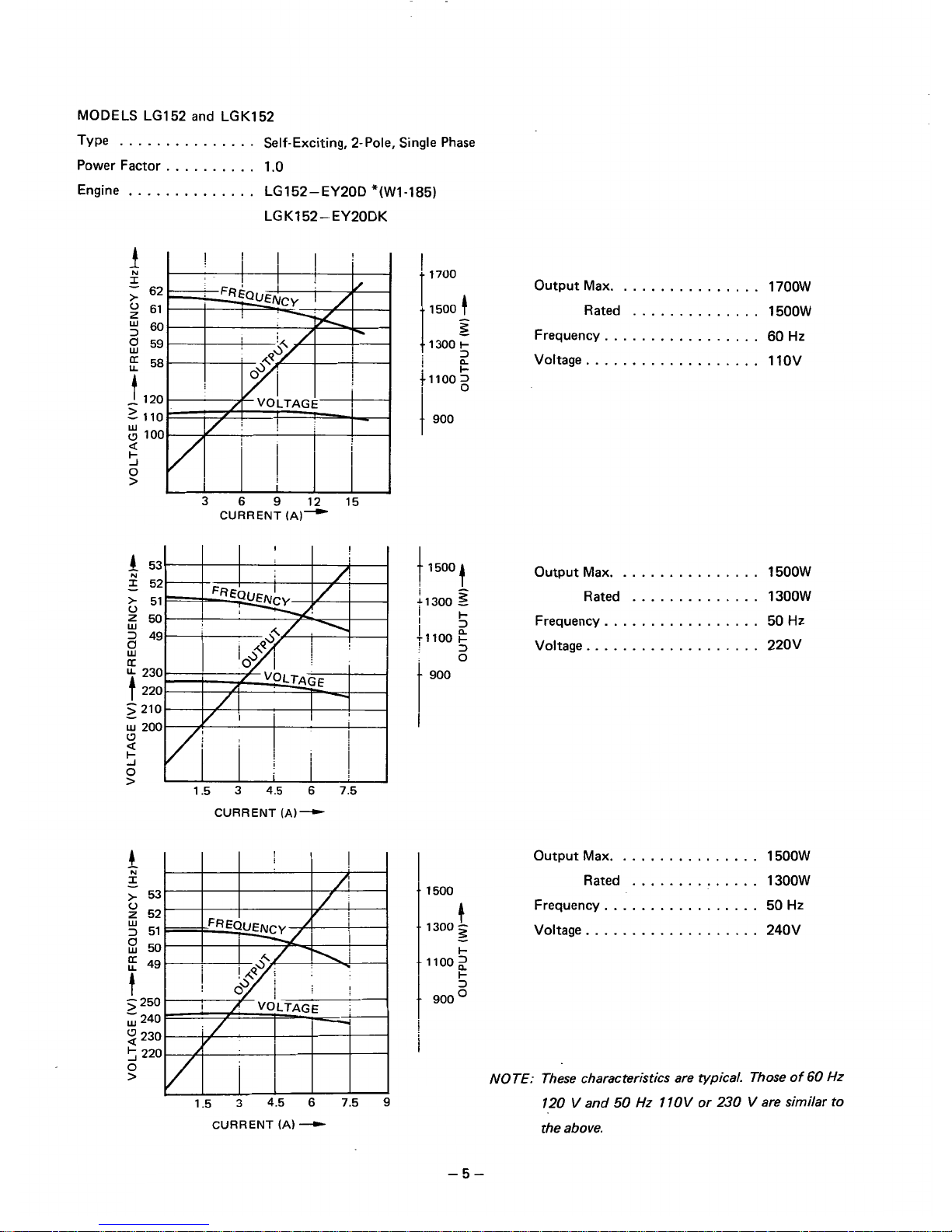
MODELS LG152 and LGK152
Type
...............
Self-Exciting, 2-Pole, Single Phase
Power Factor
..........
1
.O
Engine
. .
I
t
0
W
z
3
-
El
U
[r
t
I
>
0
W
-
a
5
0
>
4
N
-
I
>
0
z
3
W
t
............
LG152-EY20D "(Wl-185)
LGK152--EY20DK
CURRENT
(A)-
CURRENT
(A)--)
1.5 3 4.5
6
7.5
9
CURRENT
(A)
"-c
'
1700
I
1500
I
-
3
1300
I-
I-
2
ill00
I
900
1
1500
1
41300
2
I
I
I
II-
3
tlloo
E
t
0
3
1
.. 1 500
4
..
1300
2
I-
I-
-
--
1100
2
t
900:
i
i
Output Max.
...............
1700W
Rated
..............
1500W
Frequency.
................
60
Hz
Vcltage
...................
1 1OV
Output Max.
...............
1500W
Rated
..............
1300W
Frequency.
................
50
Hz
Voltage.
..................
220V
Output Max.
...............
1500W
Rated
..............
1300W
Frequency.
................
50 Hz
Voltage.
..................
240V
NOTE: These characteristics are typical. Those
of
60
Hz
120
V
and
50
Hz
1
IOV
or
230
V
are similar
to
the above.
-5-
Page 8
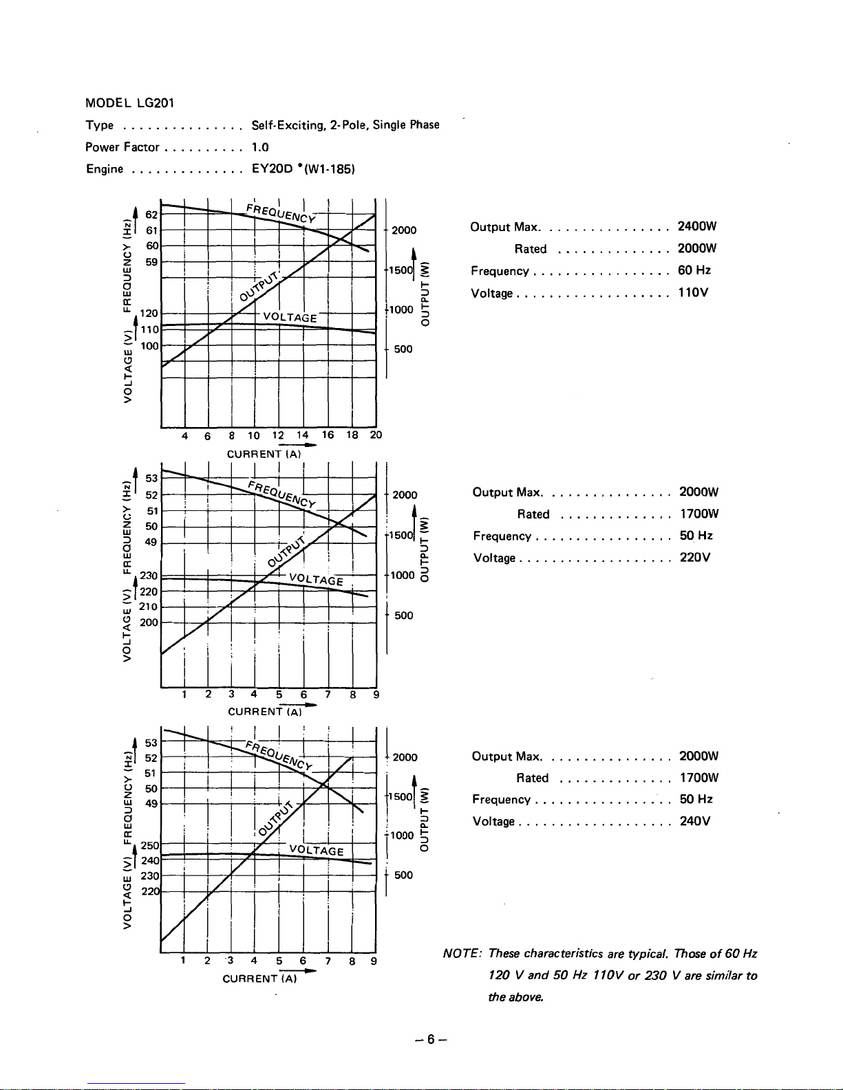
MODEL
LG201
Type
...............
Self-Exciting, 2-Pole, Single Phase
Power Factor
..........
1.0
Engine
..............
EY20D "(Wl-185)
Output Max.
...............
2400W
Rated
..............
2000W
Frequency
.................
60
Hz
Voltage.
..................
110V
i
4
2000
i
500
CURRENT
(AI
-
I
2000
11
!
504
!-
2
;loo0
5
Io
I
12-34 56 7 89
-
CURRENT
(A)
Output Max.
...............
2000W
Rated
..............
1700W
Frequency
.................
50
HZ
Voltage.
..................
220V
Output Max.
...............
2000W
Rated
..............
1700W
Frequency
.................
50
Hz
Voltage.
..................
240V
I
500
NOTE:
These characteristics are typical. Those
of
60
Hz
120
V
and
50
Hz
1
IOV
or
230
V
are similar to
ihe above.
-6-
Page 9
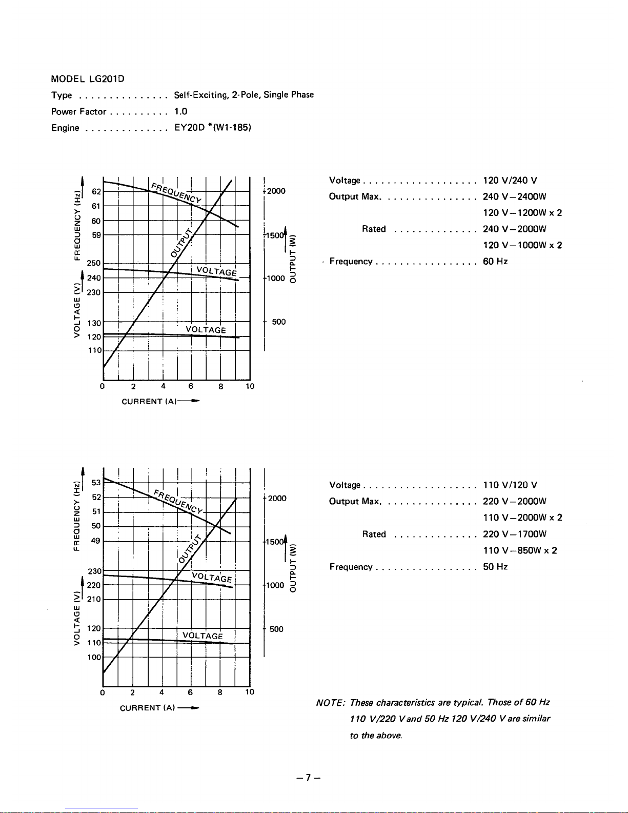
MODEL LG201D
Type
...............
Self-Exciting, 2-Pole, Single Phase
Power Factor
..........
1.0
Engine
..............
EY20D "(Wl-185)
U
-t
-
>
Lu
CJ
+
J
0
>
a
0
2
46
8
10
CURRENT
(A)-
I
j2000
I
z
"000
2
I-
.-
500
I
Voltage
...................
120 VI240 V
Output Max.
...............
240 V-24OOW
120 v-12oow x 2
Rated
..............
240 V-2OOOW
120 v-1ooow x 2
.
Frequency.
................
60
Hz
n
U
-
>
t
UI
0
a
5
0
>
CURRENT
(A)
-
Voltage
...................
1
10 VI1 20 V
Output Max.
...............
220 V-2OOOW
110
v-2ooow x 2
Rated
..............
220 V-17OOW
110 V-850W
X
2
Frequency
.................
50
Hz
NOTE: These characteristics are typical. Those of
60
Hz
110
V/220 Vand
50
Hz
120
V/240
V are similar
to the above.
-7-
Page 10
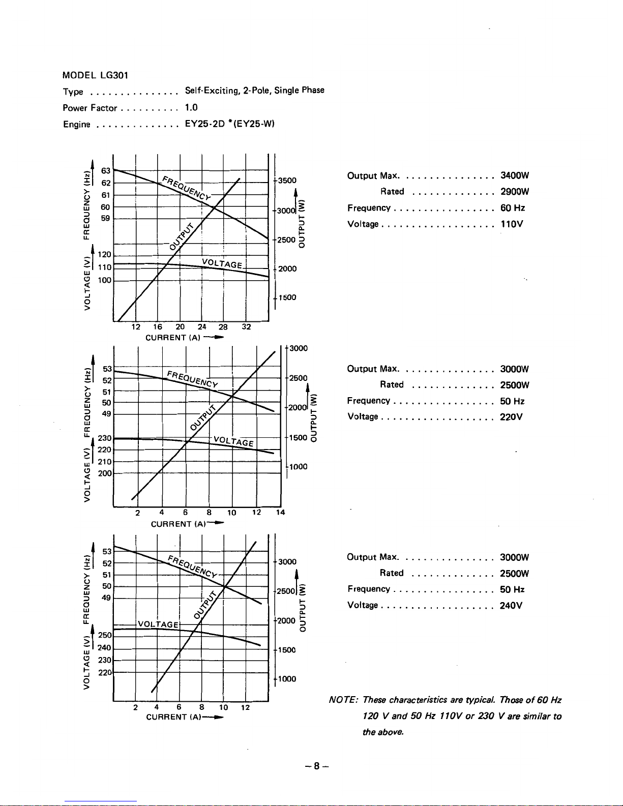
MODEL LG301
Type
...............
Self-Exciting, 2-Pole, Single Phase
Power Factor
..........
1.0
Engine
..............
EY25-2D *(EY25-W)
I
>
0
z
3
W
s
U
U
-
-t
>
W
U
a
5
0
>
I
f
3500
-1300C/z
I-
5
-2500
2
4
2000
2
4
6
8
10 12'
CURRENT
(A)-
14
Output Max.
...............
3400W
Rated
..............
2900W
Frequency
.................
60
Hz
Voltage
...................
1
1OV
CURRENT
(A)
"--c
3000
Output Max.
...............
3000W
2500
A
~~ ~
Rated
..............
2500W
-
................
200,I~
Frequency.
50
Hz
Voltage. 220V
..................
z
1500
2
1000
CURRENT
(A)---
Output Max.
...............
3000W
Rated
..............
2500W
Frequency.
................
50 Hz
Voltage.
..................
240V
..
3000
-2500
t
3
I-
2
"000
5
0
..
1
500
"000
NOTE: These characteristics are typical. Those
of
60
Hz
120
V
and
50
Hz
110V
or
230
V
are similar
to
the above.
-8-
Page 11
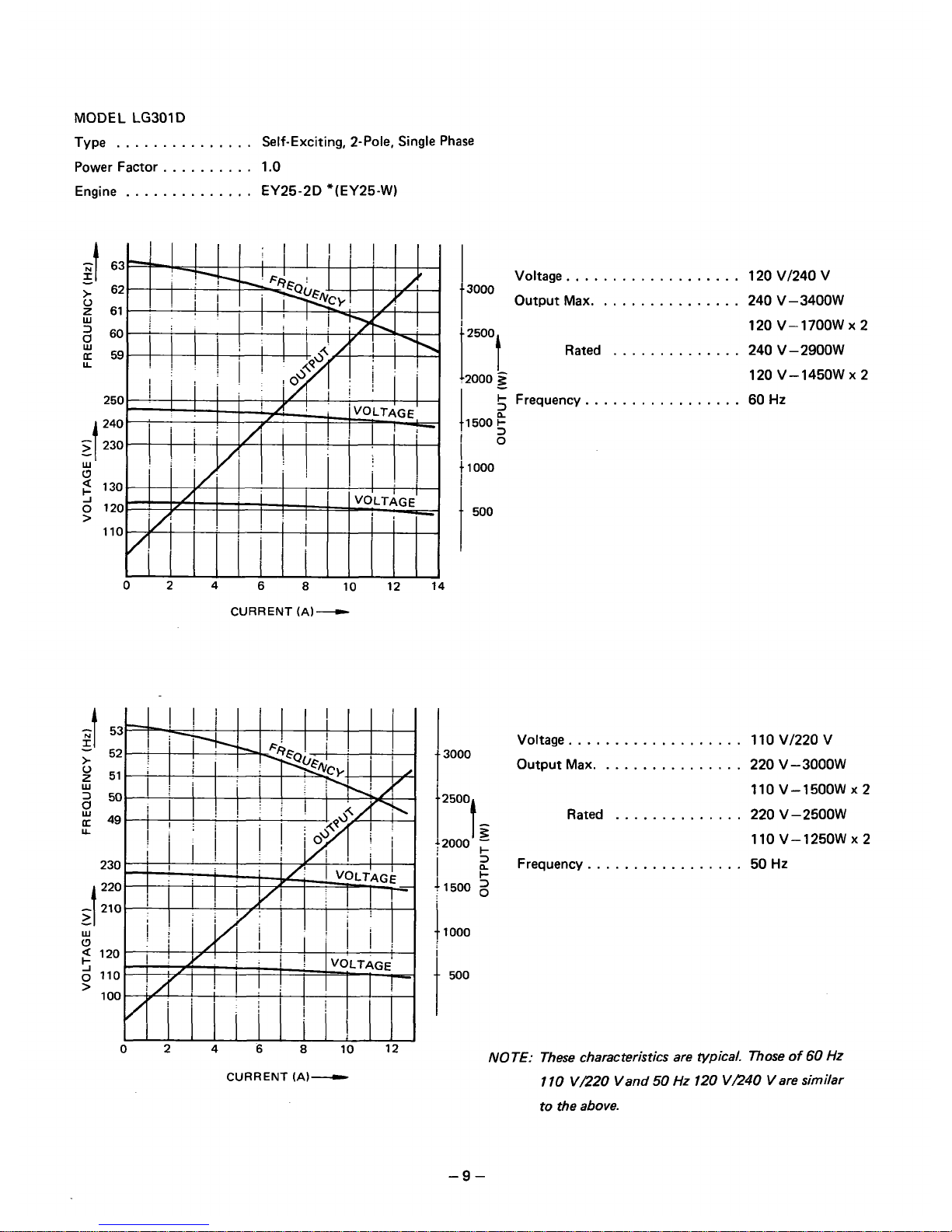
MODEL
LG301
D
Type
...............
Self-Exciting, 2-Pole. Single Phase
Power Factor
..........
1.0
Engine
..............
EY25-2D "(EY25-W)
02
4
6
8
10
12
14
CURRENT
(A)
-
CURRENT
(A)-
...................
t
3000
Voltage
Output Max. 240 V-34OOW
...............
120 VI240 V
..............
120 V-17OOW
Rated 240 V-29OOW
120 V-145OW
+
Frequency.
................
60
Hz
1500
1
1000
I
t
500
x2
x2
...................
t
3000
t2000
;
110 V-125OW X 2
i+
...............
Voltage 1 10 VI220 V
Output Max. 220 V-3OOOW
110 V-15OOW
X
2
..............
t2500t
z
Rated 220 V-25OOW
................
2
Frequency. 50
Hz
11500
2
11000
t
500
MOTE: These characteristics are typical. Those
of
60
HZ
1
10
VE20 Vand
50
Hz
120
VR40 V are similar
to the above.
-9-
Page 12
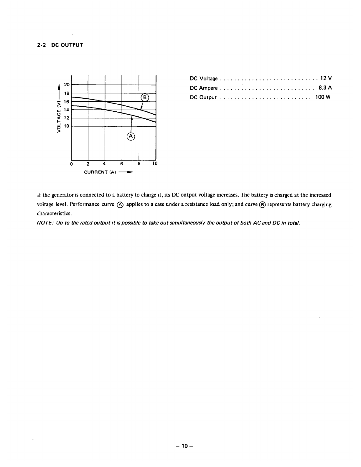
2-2
DC
OUTPUT
DC
Voltage
............................
12
V
DC
Ampere
...........................
8.3
A
DC
Output
..........................
100
W
024
6
8
10
CURRENT
(Al
-
If
the generator is connected
to
a battery
to
charge it, its
DC
output voltage increases. The battery is charged at the increased
voltage level. Performance curve @ applies
to
a
case under a resistance load
only;
and curve
(iJ
represents battery charging
characteristics.
NOTE:
Up
to the rated ouqout
it
is
possible to take out simultaneously the
output
of
both
AC
and
DC
in total.
-
10-
Page 13

3.
FEATURES
1.
2.
3.
4.
5.
6.
7.
8.
9.
10.
11.
12.
Portable, Light in Weight, Compact, and Easy to Carry
*The LC102 and LC152 employ lightweight, compact, powerful EY15D and EY2OD engines.
*All
models employ a lightweight, high-efficiency, revolving field type generator.
Solid State Ignition System
*Compared to the contact point type. this system has no contact points to wear out or replace. Therefore, mainte-
nance is reduced and constant output power can be maintained for a longer period of time.
*Easy to start with increased starting spark energy.
Extra Quiet Operation
*All
models are equipped with a large capacity, low-noise muffler.
*.a
models are equipped with a cyclone type air cleaner which reduces noise and is excellent in keeping dust out.
Effective Voltage Regulation with AVR (Automatic Voltage Regulator)
*The built-in AVR automatically regulates the exciting current to keep voltage regulation at less than
3%,
thereby pro-
tecting the load (an electrical product) and prolonging its product life.
DC Output for Battery Charging
*A DC output of 12 V 100
W
is simultaneously available with an AC output. Therefore, the generator can charge a
battery from its DC output terminal while also supplying an AC output. The combined AC and
DC
outputs must be
kept undr the rated level.
Dual Voltages Are Available
on
LC201 D and LG301 D
*A dual voltage type which supplies two AC voltages is available in the 2 kW and
3
kU' classes.
Output Voltage Waveform Close to Sine Wave
*Output voltage waveforms are close to a sine wave without a surge
so
that the load electrical product will not be dam-
aged.
Resistant to Induced Load
*Excited power is obtained from the sub coil that is wound separately from the main coil, output voltage fluctuations
are
small
as compared with load current fluctuations and constant power can be obtained. This means greater resist-
ance to loads which are subject to sharp current fluctuations-and easier starting of an induction motor.
100%
Copper Windings
*The use of pure copper which has low internal resistance for windings assures
high
efficiency and long generator life.
Easy Starting with a Recoil Starter
Trouble-Free with a
Fuse
or
No-Fuse Breaker
LGK Type Operating on Kerosene
*Automatic fuel changing system uses gasoline to start the generator and automatically changes it to kerosene in nor-
mal operation.
-
11
-
Page 14
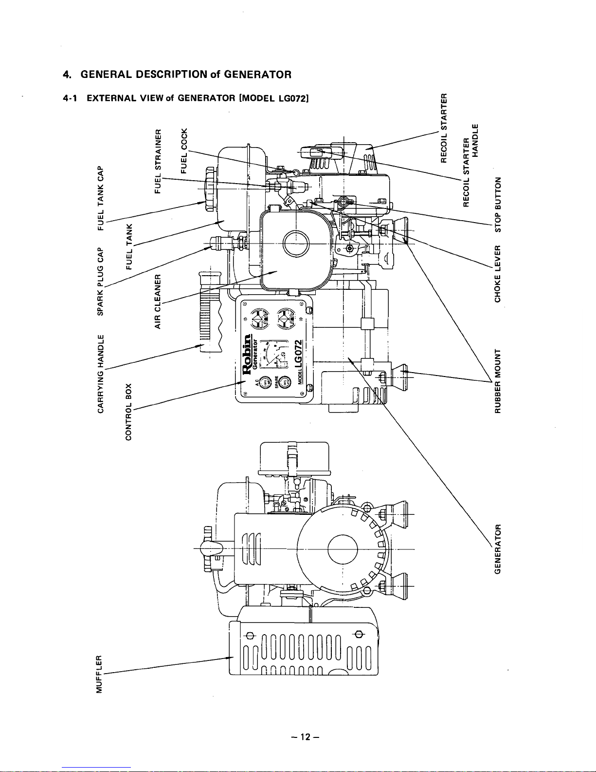
4.
GENERAL DESCRIPTION
of
GENERATOR
4-1
EXTERNAL VIEW
Of
GENERATOR [MODEL LGO721
f
-
12-
Page 15
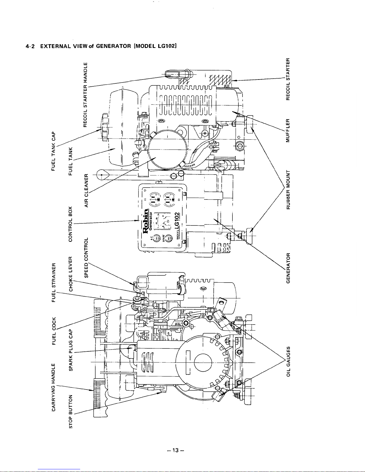
4-2
EXTERNAL VIEW
of
GENERATOR [MODEL LG1021
W
U
UI
-
13-
Page 16
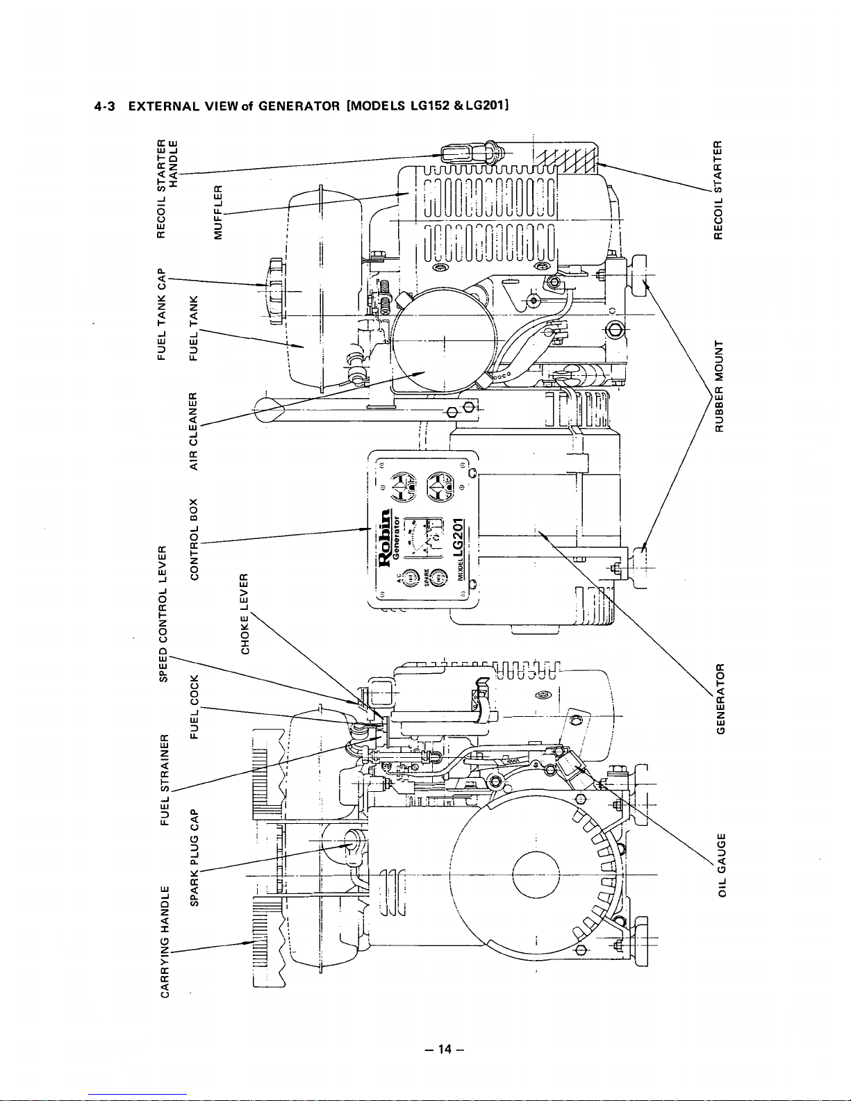
4-3
EXTERNAL VIEW
of
GENERATOR [MODELS LG152 aLG2011
-
14-
Page 17

4-4
EXTERNAL VlEWof GENERATOR [MODEL LGKlO2
&
LGK1521
-
15-
Page 18
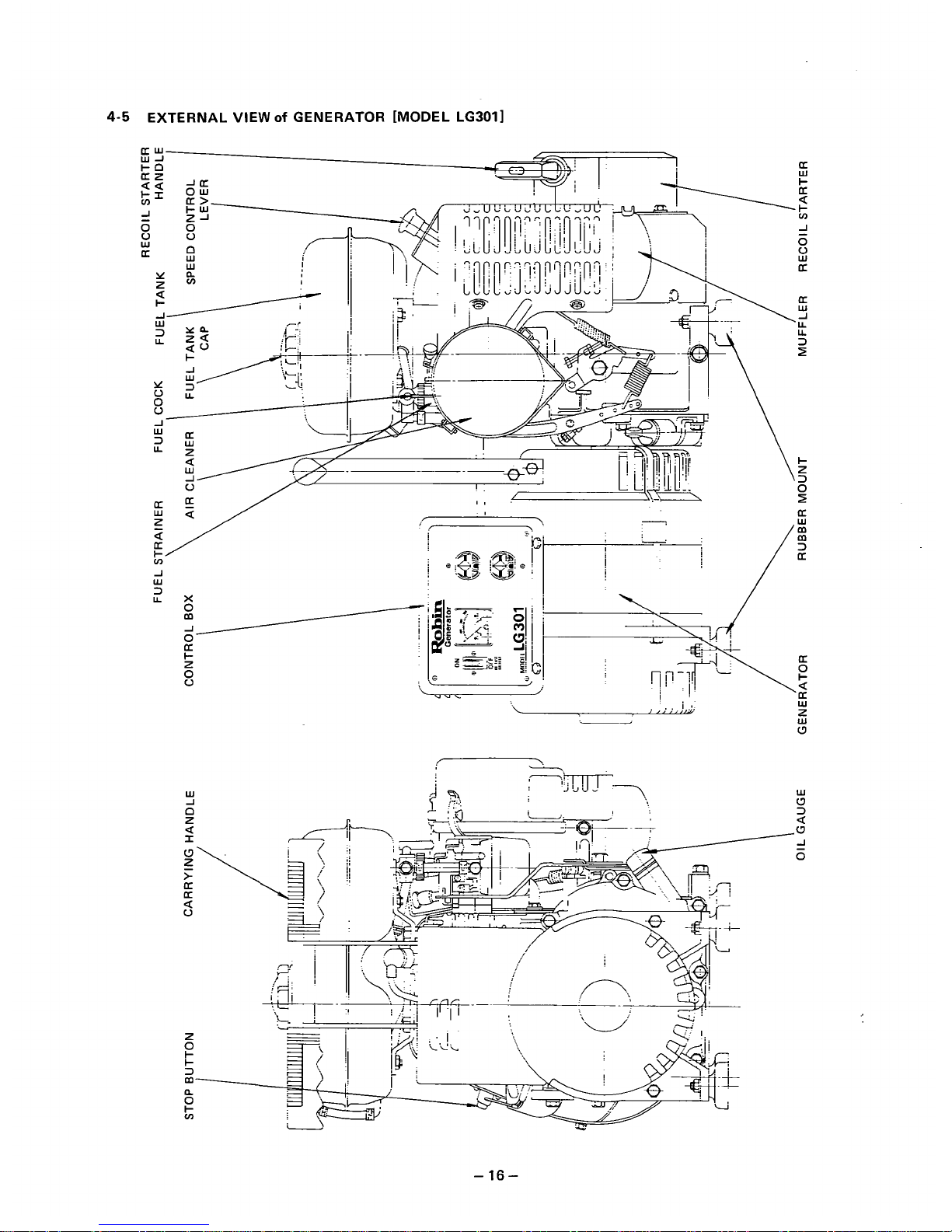
4-5
EXTERNAL VIEW
of
GENERATOR [MODEL LG301I
-
16
-
Page 19
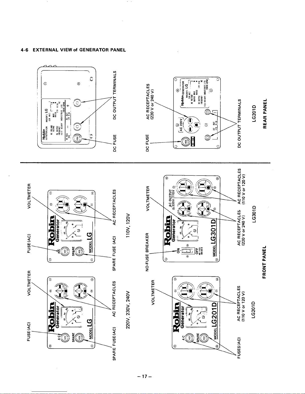
4-6
EXTERNAL
VIEW
Of
GENERATOR PANEL
75
0
W
v)
"3
.U
V
a
W
v)
,>"-
V
0
v)
c3
0
N
c
I?
n
v)
U
W
I-
W
I
0
>
-
,J
- -
v)
W
J
V
5
a
t
W
W
V
U
V
a
V
a
-
W
v)
3
U
V
a
-
W
v)
3
U
W
>
0
N
c
>-
z
-
0
>
N
d
2
2
l7
N
N
N
v)
W
U
2
v)
-17-
Page 20

5.
CONSTRUCTION and FUNCTIONS
5-1
CONSTRUCTION
-
18-
Page 21

5-2
FUNCTIONS
5-2-1
STATOR
The stator consists of a laminated silicon steel sheet core,
copper wire which winds the core. and lead wires w-hich deliver the power. The copper wire is wound into the main coil.
sub (auxiliary) coil, and
DC
coil.
AC
output power is taken
from the main coil, and
DC
output power from the
DC
coil.
The outside diameters and laminated core thicknesses
of
various models are as shown below.
Fig.
5-
1
Fig.
5-2
LG102 LG152
1
LG201 I LG301
LG072
1
LGKlO2
1
LGK152 I LG2OlD I LG301 D
D
(mm)
5.47
I
5.47
1
6.97 6.97 6.97
(inch)
139 139
'
177
1
177
i
177
2.76 3.94 2.17
i
2.76 2.36
(inch)
70
:
100
55 70 60
(mm)
1
L
Table
5-
1
-
19
-
Page 22

5-2-2
ROTOR
The rotor consists of a laminated silicon steel sheet cover
with a field coil wound arount it and cooling fans and slip
rings at both ends of the shaft. The field coil leads are connected to the slip rings and direct current
(DC)
to the field
-
coil turns the rotor and magnet. The cooling fans cool the
generator by drawing cooling air from the slip rings 2nd dis-
charging it
through
the fans.
BEARING
~ ~
Fig.
5-3
Fig.
5-4
i
LG102 I LG152
LG2OlD
.
LG301D
i
LGKlO2 ' LGK152
LG201
I
MODEL
I
LG072
LG301
I
I
,
(mm) I 55 70
I
60 70
100
(inch)
2.17 2.76
I
2.36
I
2.76
I
3.94
I
Table
5-
2
-
20
-
Page 23

5-2-3 BRUSHES
~~ ~ ~ ~ ~ ~
~.
An
exciting current is supplied from the
AVR
to
the rotor.
The brushes are made
of
carbon and the brush-holders of
'
plastic. It is necessary to keep the contact pressure between
the brushes and slip rings within specific limits. Therefore,
care must be taken about brush length. (See
9-3
BRUSHES.)
5-2-4 AVR (AUTOMATIC VOLTAGE REGULATOR)
The automatic voltage regulator employs an electronic cir-
cuit to automatically reglate voltage.
Fig.
5-6
5-2-5 VOLTMETER
The voltmeter comes in two types, a
150
V
maximum type
and a
300 V maximum type. The voltmeter indicates generator output voltages. The generators with a generated voltage -of 110
V
or 120 V use the 150 V maximum type volt-
meter; and those
6f
220
V,
230
V,
and
240
V
specifications
and dual voltage type generators use the
300
V
maximum
type voltmeter.
300
V
MAX.
150
V
MAX.
(220
V.
230
V.
240
V)
I110
v,
120
V)
-
~
-
.~~
Fig.
5-7
-
21
-
Page 24

These prevent output over current and short circuit over cur-
rent. If a generator is operated at more than the maximum
current, the temperature inside the generator rises
so
that
the insulations are adversely affected, possibly causing electric shock or current leakage. The fuse and no-fuse breaker
prevent the insulations from deteriorating and protect the
generator.
CAUTION:
Use
fuses
of
the
correct capacity.
FUSE
5-2-7 RECEPTACLE and AC PLUGS
These are used for taking
AC
output power from the gener-
I
~~ ~ ~
RECEPTACLES
ator. Each generator has two receptacles (three or four receptacles for the dual voltage type). The 125
V
maximum
(1
10
V,
120
V)
type and 250 V maximum
(200
V,
230
V,
240
V)
type differ from each other in the shape of the indi-
vidual output terminals.
"
L;
AC PLUG
The
AC
plugs
also
differ in shape between the 125 V maxi-
mum type
and
250 V maximum type. The same number of
(220
v,
230
v,
240
VI
(110
v,
120
V)
AC
plugs as that of receptacles are provided.
250
V
MAX
125
V
MAX
..
~.
~
~-
~.
Fig.
5-9
5-2-8 TERMINALS
The terminals are for producing
DC
output power and
come in two colors, red and black. The red one is positive
(+)!
and the black one negative
(-).
RED
-
22
-
Page 25

5-2-9
FRONT
COVER
The front cover is an aluminum die casting and is mounted
on the main bearing cover
of
the engine. It has vents to discharge cooling air from the generator and the vents are designed to prevent fingers from entering.
5-2-10 REAR COVER
The rear cover is also an aluminum die casting
and
has
a
It
has bosses inside for holding the brushes and vents for
taking cooling air in. The vents are designed to prevent
fingers from entering.
5-2-11 RUBBER MOUNTS (RUBBER VIBRATION
I
SO
LATO
RS)
Specially designed rubber pads for controlling generator
vi-
bration and dislocation. These are made of superior quality
rubber material for optimum shape and hardness.
5-2-12 CARRYING HANDLE
The
LC072
has a single-hand carrying handle and the other
models have two-hand carrying handles. The handles differ
in height from one model to another and feature a rubber
grip(s) for easy holding.
~~201
D,
3oi
D
LG072.102
Fig.
5-
1
I
LG K152
LGKl02'
.
~ ~~ ~
.~
~"
~
..~
"
-23-
Page 26

5-3
DESCRIPTION
Of
GENERATOR OPERATION
5-3-1 PRIMARY EXCITING ACTION
One of the differences between the old type and the new
-
type is that the new type has an exciting coil
(EC)
while
the old type does not.
The old type used a rotor of carbon steel sheets that started
the primary exciting action of the generator with its residual
r-----l
I
I
magnetism.
This
type loses its residual magnetism if the gen-
1'
I
erator is disassembled and stored and may fail to generate
I
electric power when it is started after storage. The new type
FC
I
/
I
p
,
I
EC
I
I
\
I
I
is equipped with an exciting coil on the engine magnet for
primary exciting action to eliminate such an occurance.
The primary exciting action of the new type is explained
below.
When the generator is started, the permanent magnet on the
engine rotates to generate voltage in the exciting coil.
This
voltage is regulated by a diode in the
AVR
to feed current
into the generator field coil
(FC).
(See Fig.
5-15.)
The rotor turns an electromagnet with that current and
rotates
so
that voltage is generated in the stator coils (main
coil, sub coil, and
DC
coil). The voltage generated in the sub
coil is regulated by the
AVR
to feed current in order to in-
crease the field and current. (See Fig.
5-16.)
As
a result,
the rotor magnetism increases.
Ths
operation is repeated to
generate the rated voltage at
50
Hz
or
60
Hz
in the main
coil and
DC
coil.
5-3-2 VOLTAGE REGULATING MECHANISM
Connect a load to the
AC
output terminal and increase cur-
rent. Output voltage will vary as shown in Fig.
5-17
depending on whether an automatic voltage regulator is used or not.
When
AC
output is drawn, the engine becomes loaded and
its rpm falls.
Also,
the
AC
voltage falls due to the voltage
drop caused by the internal resistances of the coil. The
AVR
caused by the internal resistances of the coils. The
AVR
detects this voltage drop and its built-in
SCR
automatically
increases the current that
floCs
to the field coil.
As
a result,
the rotor magnetism increases, the voltage decrease caused
by the load current
is
raised, and the output voltage
is
kept
constant. If the
AC
output is reduced, the
SCR
operates in
the opposite way to similarly keep the output voltage constant.
I I
ENGINE MAGNETO
!"-"-J
Fig.
5-
15
MC
i
Fig.
5-
16
WITH 'AVR
-A
Fig.
5-
17
-
24
-
Page 27

6.
1.
2.
3.
4.
5.
6.
SAFETY PRECAUTIONS
Use
extreme caution near gasoline. A constant danger of explosion
or
fire exists.
Do not fill the fuel tank with gasoline while the engine is running. Do not smoke or use open flame nea the fuel tank.
Be careful not to spill fuel when refueling. If spilt, wipe it and let dry before starting the engine.
Do
not place inflammable materials near the generator.
Be careful not
to
ptt gasoline, matches, gunpowder,
oil
cloth, straw, trash and any other inflammables near the genera-
tor.
Do
not operate the generator in a room, cave
or
tunnel. Always operate in a well-ventilated area.
Otherwise the engine may become overheated and also, the poisonous carbon monoxide contained in the exhaust gases
will endanger human lives. Keep the generator at least
1
m
(4
feet) away from structures or facilities during use.
Operate the generator
on
a level surface.
If the generator is tilted or moved duricg use, there is a danger of fuel spillage and a chance that the generator may tip
over.
Do
not
operate with wet hands
or
in the rain.
Severe electric shock may occur.
If
the generator is moistened by rain or snow: wipe it and fully dry it before starting.
Don't pour water over the generator directly or wash it with water.
If the generator is wet with water, the insulations will be adversely affected and may cause current leakage and electric
shock.
Do
not connect the generator to the commercia! power lines.
This
may cause a short-circuit or destroy the generator. Use a transfer switch for connecting with indoor wiring.
NOTE: The parts numbers of the transfer switches and of the plastic box
to
store them are as shown in Table
6-
1.
Part
No.
!
Part
Name
Q'ty Current
365 45604
08
.
TRANSFER SWITCH
i11
15A
367 45605
08
1
TRANSFER SWITCH
i1
30A 367 43008
08
PLASTIC
BOX
i1
30
A
Table
6-
1
7.
Use fuses of the correct capacity.
If the generator rpm is increased exorbitantly in the overload condition by using a fuse in excess of the rated capacity,
the generator could be burnt and the
AVR
be damaged.
CAUSTION: if the fuse is burnt out or the circuit breaker tripped off as a result of using an electrical appliance, the
cause can be an overload or a short-circuit. In such a case, stop operation immediately and carefully check the e!ectrical
appliance and AC plugs for faulty wiring.
-
25
-
Page 28

7.
RANGE
of
APPLICATIONS
Generally. the rated power of an electrical appliance often refers
to
the amount of work that can be done by it. The electric
power required for operating an electrical appliance is
not
necessarily equal
to
the amount of work that can be done by
it.
Electrical products generally have a label showing their rated voltage, frequency, and power consumption (input power). The
power consumption of an electrical products is the power necessary for using it. When using
a
generator for operating an
electrical product, however, the power fxtor and starting current must
also
be taken into consideration.
Determine the required capacity of your generator from the power required for operating electrical products that are classified as follows:
1.
2.
3.
4.
Incandescent lamps, hot plates, etc. with a power factor of
1
.O
Total power consumption must be equal to or less than the rated output
of
the generator.
Example:
A
generator with a rated output power of
1000
W
can light ten
100
W
lamps.
Fluorescent lamps, mercury lamps, etc. with
a
smaller power factor
Select a generator with a rated output equivalent to
1.2
to 2 times the power consumption of the load.
Example:
A
generator with a capacity
of
100
W
to 160 W is necessary for lighting a
80
W
fluorescent lamp. A generator
with a rated output of
1000
W
can
light
6
to 10
40
W
fluorescent lamps.
NOTE: Wattage of the fluorescent lamp generally does not indicate the power consumption but indicates the ouwut of
the lamp. Therefore, if the fluorescent lamp has
no
special indication as to the power consumption or input power,
efficiency should be taken.into accounts as explained
in
Item
5
on
the followingpage.
Electric
tools,
etc. that are driven
by
a motor
Power
1
.Z
to 3 times the power consumption of a motor-driven tool is required for starting
so
select a generator with a
maximum output
1.3
to
3
times the power consumption
of
the load.
Example:
A
300
W
motor-driven drill requires a generator with a maximum output of
400
to
900
W
or more.
Water pumps, compressors, etc. that are driven
by
a
motor which
is
loaded at starting
3
to 5 times the power consumption of the load is necessary for starting
so
select a generator with a maximum output
3
to
5
times its power consumption.
Example:
A
water pump with a power consumption
of
400
W
requires a generator with a maximum output
of
1200
to
2000 W or more.
NOTE
7:
Motor-driven products mentioned in
Items
3
and 4 required the aforementioned generator capacities
only
when starting their motors. Once their motors are started, the products consume only about
1.2
to 2 times their rated
power consumption
SO
that the excess po wer generated by the generator can be used for other electrical appliances.
NOTE
2:
Motor- driven products mentioned in Items 3 and 4 vary in their required motor starting power depending
on
the
kind
of motor and start-up load. If it
is
difficult to determine the optimum generator capacity, select a generator
with a larger capacity.
-
26
-
Page 29

5.
Appliances without any indication as to power consumption
Some appliances have no indication as to power consumption; but instead the work load (output) is indicated. In such a
case, power consumption is to be worked out according to the numerical formula mentioned below.
(Output of electrical appliance)
(Efficiency)
=
(Power consumption)
Efficiencies of some electrical appliances are
as
follows:
Single-phase motor
..........
0.6
Three-phase motor
..........
0.65
-
0.9
Fluorescent lamp
0.7
-
0.8
-
0'75
3
The smaller the capacity, the worse the efficiency,
and vice versa.
...........
Example
1:
A
40 W fluorescent lamp means that its luminous output is
40
W.
Its efficiency is
0.7
and accordingly,
power consumption will be
40
+
0.7 = 57
W.
As
explained in Item
2,
multiply this power consumption
value
of
57
W
by 1.2 - 2 and
YOU
will get the figure of the necessary capacity of a generator. In other
words, a generator with a rated output of 1000
W
capacity can light
9
-
14 40 W fluorescent lamps.
Example
2:
Generally speaking, a
400
W
motor means that its work load is 400
W.
Efficiency
of
this motor is
0.7
and
power consumption will be 400
+
0.7
=
570
W.
When this motor is used for a motor-driven tool, th2 capa-
city of the generator should be multipled by 1.2 to
3
and
570
W
as explained in the Item
3.
Model
Frequency
hot plate, etc.
Incandescent lamp,
Fluorescent lamp,
mercury lamp, etc.
Motor-driven tool,
general-purpose
motor. etc.
Water pump,
compressor, etc.
LG072
LG102
I
LGK102
I
LGK152
,
LG301D*
I
LG301DC
LG 152
I
LG201 LG301
I
50HZ
60HZ
2500W j 2900W
2000W
600W
1
700W 1 8OOW j lOOOW , 1300W ! 1500W 1700W
60Hz
50Hz
60Hz
50HZ
I
60Hz I 50Hz I 60Hz I 50Hz
about
I
about
about
.
about
about about
1
about
about
I
about
1
about
350W
I
400W I 450W
,
60OW
I
850W
1
1 OOOW , 1 lOOW
1
1300W
I
1650W 19OOW
I
about i about I about i about about about about about I about I about
350W
;
400W I 500W I 600W I 750W I 850W
;
looow
;
1200w
I
1500 I 1700W
about
'
about
i
about
about.
about about
'
about about
1
about
about
150W
I
18OW I 230W I 250W I 350W
I
400
,
500W I 600W : 750W I 850W
*The load that ca be connected to one 11011
20
V
receptacle
of
the dual voltage type
is
up to only
one half
of
the atove wattages.
Table
7-
1
-
27
-
Page 30

NOTE: Wiring between generator and electrical appliances
1.
Allowable current of cableUse a cable with a allowable current that
is
higher than the rated input current of the load (electrical appliance). If the
input current is higher than the allowable current of the cable used, the cable will become excessively heated and de
teriorate the insdation, possibly buring
it
out. Table
7-2
shows cables and their allowable currents for your reference.
2.
Cable length
If a long cable is used, a voltage drop occurs due to the increased resistance in the conductors
so
that the input voltage
to the load (electrical product) decreases. As a result, the load can be damaged, table
7-2
shows voltage drops per
100
meters of cable.
Current Amp.
0.75
~
7 3010.1
a
2.477
i
2.5~
I
av
I
12.5~
U
-
1av
12v 15v
1.25 12 5010.1a
1
1.486 i 1.5~ ' 5v . 7.5~
n
-
-
-
I
-
%
e
2
.o
i
17
:
3710.26
I
0.952
IV
3v 1 5v
2
15v 12v
av
'
IOV
3.5
'
7.5V
~
6.5V
5V
0.51
7
-
1
1.5V I 2.5V ! 4V 4510.32
23
5.5
5V
4V
3.5V
2.5V 2V
1V
-
0.332
7010.32
35
Table
7-2
-
28
-
Page 31

8-1
METERS
8-1
-1
VOLTMETERS
AC and
DC
voltmeters are necessary. The approximate
AC
voltage ranges of the voltmeters to be used for various types
of generators are as follows:
0
to 150
V:
Type with an output voltage of
110
or 120
V
0
to 300
V:
Type with an output voltage of 220, 230, or
240
V
0
to
150
V,
0
to
300
V:
Dual voltage type
The DC voltmeter range
is
approximately from
0
to
200
V.
Fig.
8-
1
FOR
AC
FOR
DC
~~
.
~~
..
8-1
-2
AMMETERS
""
.
AC and DC ammeters are necessary.
An
AC ammeter with a
'
range that cap be changed according
to
the current rating of
a given generator is most desirable. (About
10
A, 20 A,
100
A)
The DC ammeter range
is
approximately from 0 to
15
A.
:
FOR
AC
FOR
DC
"~
"
~.
~
~.~
.
~~
~..~~
-~
~ ~ ~ ~
."
."
Fig.
8-2
8-1-3 FREQUENCY
METER
.
.
~.
~
~
.~~
Frequency range: About 45 to
65
Hz
NOTE:
Be careful of the frequency meter's input voltage
range.
~~
~~.
-~
~
~
"
~~~~~~
Fig.
8-3
~ ~~ . ~~
-
29
-
Page 32

8-1
-4
TESTER
Used for measuring resistance, etc.
8-1-5 MEGGER TESTER
Used for measuring generator insulation. Select one with a
:
voltage capacity of
500
V.
8-1
-6
TACHOMETER
..
~
~
.
~ ~ ~
"
-~
"
"
~~
.
-%
;.
There are various types of tachometers, such as contact-less
-
type: contactftype, and strobe type. The contact type can
j
C_@JTA~TLE~$
TYPE
be used only when the generator and engine have been disassembled. The contact-less type
is
recommended.
Q
=.
3.
-
-
\
C0NTisC.T
TYPE
\
STRO-BE-
IYP-E
-~
~
.~
~~
-
-
~~
.~
~
"
..
.~
-~
-~
~
-
-
Fig.
8-6
-30
-
Page 33

8-2
AC OUTPUT MEASURING
TO
A
Fig.
8-
7
;e a circuit like the one shown in Fig.
8-7
for measuring
AC
output. A hot plate or lamp with a power factc
)r
of
1
.O
may
be used as a load. Adjust the load and rpm, and check that the voltage range is as specified in Table
8-1
at the rated amperage
and rated rpm.
Ratedvoltage
I
11OV
1
12OV
1
22OV 230V
238-245V
Voltagerange
'
108-115V j 118-125V I 218-225V 1 228-235V
I
240
V
I
8-3
DC OUTPUT MEASURING
Table
8-
1
00
SWITCH
@
DC
TERMINAL
Fig.
8-8
Switch the power on: adjust the load to
8.3
A
at the rated rpm, and check that the voltage is within the range of
13
to
11
V.
NOTE: If
a battery
is
connected as the load, the ouwut voltage increases by about 1 to
2
V,
possibly causing battery over-
charge. Control battery liquid level during charging to prevent overcharging.
8-4
MEASURING INSULATION RESISTANCE
Connect a megger tester to one of the two receptacle output
terminals and the ground terminal, then measure the insulation resistance.
(Ifyourgenerator is the no-fise breaker type,
close the no-fuse breakerand measure it. If yourgenerator
is
the dual voltage type, any voltage receptacle may be used.)
An
insulation resistance of 1 megohms or more is normal.
(The original insulation resistance at the time of shipment
from the factory is
10
megohms or more.) If it is less than
1
megohm, disassemble the generator and measure the
insulation resistance of tne stator, rotor and control box
individually.
Fig.
8-9
-
31
-
Page 34

STATOR
Measure the insulation resistance between the red or white
coupler from the stator and the core.
0
ROTOR
Measure the insulation resistance between the core and
one of the slip rings
of
the rotor.
*CONTROL
BOX
.
.
~-
~~~~~..
~ ~ ~~ ~ ~
~.
.
~ ~ ~
Measure the insulation between the live parts and the
:
casing or grounded part.
i~-
=
~=
=
.~
_~~c
"
.g
.~
~~
Any
part which has an insulation resistance of less than
1
megohm has a faulty insolation, which can cause electric
shock or leakage. Replace such parts.
Fig.
8-
12
-32
-
Page 35

9.
CHECKING FUNCTIONAL MEMBERS
STATOR ASS'Y
9-1 STATOR ASSEMBLY
9-1-1
MEASURING WINDING RESISTANCE
Check the resistances of the leads from the stator with a
tester. (See Fig.
9
-
1
.)
Check all the leads mrhich are shown by type in the tables
below.
Any
lead which is inactive is faulty.
NOTE: Testers are not
so
accurate that some margin
of
er-
ror must be taken into account when reading the tester
against the values shown in the Tables
9-
I,
9-2,
and 9-3.
I
WHITE
I
0.7
-
6.5!2
I
0.1
-
0.9R ! 2.5
-
5.0R
I
Table
9-
1
LG152, LG201, LG301, LGK152
WHITE
0.2 - 3.1R
I
1.5 - 4.lQ
BLUE-BLUE
0.1
-0.5R
Table
9-2
Fig.
9-
1
LG201
D,
LG301
D
Wire
cotor
'
RED
BLACK
1
GREEN
I
WHITE
I
0.4 - 1.3R
0.4
-
1.3s1 ; 1.7 - 3.6R
A
BLUE-BLUE
0.1
-
0.5R
Table
9-3
9-1
-2
MEASURING INSULATION RESISTANCE
ROTOR
Refer to
8-4
MEASURING INSULATION RESISTANCE.
9-2 ROTOR ASSEMBLY
9-2-1
WINDING RESISTANCE MEASURING
SLIP
RING
Check the resistance between the two
slip
rings with a test-
er. (See
Fig.
9-2.)
The resistance is normal if it is anywhere from
6
ohms
to
13
ohms.
TESTER
Fig.
9-2
-33-
Page 36

9-2-2
MEASURING INSULATION RESISTANCE
Refer to
8-4 MEASURING INSULATION RESISTANCE.
9-2-3
CLEANING SLIP RINGS
The slip ring surfaces must be uniformly bright. Slip rings
showing black spots, excessive wear, or uneven wear must
be repaired.
A
stained slip ring lowers generator efficiency
and output voltage. Polish the slip rings with fine sandpaper
while turning the rotor until rough spots disappear. Care
should be taken not to touch the rotor coils with the sandpaper. (See Fig.
9
-3
.)
9-3 BRUSHES
The brushes must be smooth where they contact the slip
rings.
If
not, polish smooth the brushes with sandpaper.
A
brush that is not smooth produces arcs between the brush
and slip ring leading to possibie damage. Usable brush lengths
are from
5
mm to
15
mm as shown in Fig.
9-4.
A
brush
shorter than
5
mm must be replaced because decreased contact pressure between the brush and slip ring lowers generator efficiency and output voltage.
Fig.
9-3
f
i15mm-5mm
15m.m-5m
Fig.
9-4
9-4 AVR (AUTOMATIC VOLTAGE REGULATOR)
AVR
trouble may be identified.by simply koking at the
AVR,
or by checking the inter-lead resistance with a tester, or actu-
ally mounting it in the generator and operating it.
9-4-1
AVR TROUBLE IDENTIFICATION
by
APPEARANCE
If
an
AVR
electronic part is burnt dark,
or
the surface epoxy resin melted, it often indicates indicates
AVR
trouble.
9-4-2
IDENTIFYING AVR TROUBLE
bf
CHECKING
INTER-LEAD RESISTANCE
Check the inter-lead resistance
of
the
AVR
with a tester.
(See Fig.
9-5.)
If the tester readings vary greatly from the
values specified in the tables below, the
AVR
is faulty.
NOTE:
Take tester inaccuracy into account in reading the tester.
TESTER
Fig.
9-5
-34-
Page 37

MODEL LG072, LG102, LGKlO2
I
!
I
Tester polarity
Yellow Red White
j
Green Brown
I
1.
i
I
i
I
m
'
600K
1MR
75K - 120KR
1
One
wire:
OR
!
m
1
400K - 500KQ I 75K - 120KS1
I
i
One wire:
09
1
7K- 10KQ
~
!
Another:
m
:
7K - 1OKR
Yellow
I
Red
I-
I
i
250K - 300KR
m
1
400K - 500KR
I
-
I-I-
120K - 130Kfl
1
m
i
200K - 220KR
I
~
i
250K - 300KR
i
-
-
m
White
j
45K - 50Ka
-
:
120K- 300KR
1
-
m
'
45K -5OKR
i
~~~ ~~~ ~
-
~~~ ~
j
500K- 1MR
j
75K- 11OKR
I
i
-----
"
~~
Green
-
j
7K-9KS1
-
-
t
200K - 250KR I 40K - 46Ka
I
m
I
-
400K - 500KR ' 75K - 11OKR
'
-
'
7K-9KR
-
Black
400K
-
500KQ 40K
-
46KR
m
-
*Upper rows are for the 220, 230, 240 V specifications; lower rows for the 110, 120 V specifications.
Table
9-4
MODEL LG152, LG201, LG301, LGK152, LGZOID, LG301D
Tester polarity
!
I
1
Yetlow
j
Red White
:
Green
i
Brown
1
!
i
I
Im
i
700K- 1MR
~
72K - 120KQ
Another:
One wire:
OS2
i
6.5K - 10KQ
Yellow
t
I
m
400K - 500KR 72K - 120KR
Another:
oo
I
I
!
:
250K - 300KR
Red
m
I
400K - 500Kn
._
-
130K - 140KR
m
220K - 250KQ
White
I
-
i
130K - 140KR
I
-
m
i
45K - 50KSL
600K
-
1MS2
i
70K - 110KQ
i
400K - 500Kn - 70K - 11OKR
I
i
-
-
7K - 9.5KR
I
6.5K - 8.5KQ
Green
-
-
I
400K - 500KR , 40K -46KR
1
200K - 300Kfi i 40K - 46Kn
j
m
I
-
-
m
!
Black
-
-
*Upper rows are for the 220, 230, 240 V specifications; lower rows for the 110, 120 V specifications
and the dual voltage
type.
Table
9-
5
9-4-3 IDENTIFYING AVR TROUBLE
by
MOUNTING AVR in THE GENERATOR and OPERATING AVR
SCR
or transistor damage cannot be detected
by
simply
looking at
the
AVR
or checking
the
lead
resistances.
Check
it
by
mounting
the
suspectedly faulty
AVR
in
a
normal generator, or mount a normal
AVR
in
a
generator which
fails
to generate
voltage.
-
35
-
Page 38

9-5
FUSE HOLDER
and
NO-FUSE HOLDER
9-5-1 FUSE HOLDER
Check that a fuse is
in
the fuse holder and check its conti-
nuity with a tester. (See Fig.
9-6.)
If it carries current, it is
normal.
FUSE
HOLDER
If there is no current, take the fuse out and check it for
continuity. If the fuse carries current, the fuse holder is
faulty. If the fuse carries no current, replace it with a fuse
of the correct capacity, and check the fuse holder again for
continuity.
Fuse capacities are shown
in
the table below.
Fig.
9-6
TESTER
50Hz
60Hz
110V
I
220V
I
230V
I
240V 11ov
I
120v
DC
I
I
I
I
6A
I
3A
I
3A 7A
6A
I
3A
LG072
I
10A
1
10A
4A 4A 10A
8A
~
4A
LG 102
.
LG152
15A 6A
I
6A
.
6A 15A
I
15A
i
LG201
20A
15A 8A
1
8A 8A
;
20A
Table
9 - 6
50Hz
1201240V
!
1 1 Ol220V
1
1 Ol220V
60Hz
1201240V
DC
LG2Ol-D 10A
8Ax2
:
10Ax 2 10Ax 2
8Ax2
"LG301, LG301 D
employ
a
no-fuse breaker.
Table
9-
7
9-5-2 NO-FUSE BREAKER
Only the
LC301
and
LG301D
have a no-fuse breaker.
Push the power switch off and check continuity. If no current flows, it is normal. Then push the power switch on and
check continuity again. If current flows, it is normal.
If the breaker is a two-pole type, the two pairs of terminals
must carry current.
Fig.
9-7
-36-
Page 39

9-6
RECEPTACLE
and
AC PLUG
Check the current-carrying parts
of
the receptacles and AC plugs and their leads and plastic parts
for
bums.
9-7
VOLTMETERS
Apply AC voltage to a terminal and check if the voltmeter
reads normal.
9-8
DIODE STACK ASSEMBLY
"
Fig.
9-9
The internal circuitry of the diode stack assembly is as
shown
in
Fig.
9-9.
Check inter-terminal continuity with a
tester as shown in Fig.
9-10
to see that the results are as
shown in Table
9
-8.
VOLTMETER
Fig.
9-8
/_1
-I
+I
--"--I
Fig.
9-
10
NOTE:
A
$
B
Current flows from
A
(+)
to
B
6).
C
++"
D
Current does not flow
from
C
(+I
to
D
(-1.
-
Check both terminals.
Table
9-8
-37
-
Page 40

9-9
PRIMARY EXCITING CIRCUIT
As described in
5-3
DESCRIPTION
of
GENERATOR OP-
ERATION,
the primary exciting coil is in the magneto
mounted on the engine, and the AVR has a circuit for it.
9-9-1
EXCITING COIL
The normal inter-terminal resistance of the exciting coil is
about
10
to
30
ohms.
Its voltage at the rated rpm is about
AC
10
to
30
V.
Check the resistance and voltage with a test-
er to see if they meet these requirements.
9-9-2
OTHERS
No
output voltage from the generator.
Fig.
9-
10
If the trouble cannot be detected by Step
9-9-
1
above, check the primary exciting circuit as follows:
A. Disconnect the control box and operate the generator at the rated rpm. Disconnect the two yellow wires from the excit-
ing coil to the AVR, and momentarily connect the positive
(+)
and negative
(-)
leads of a battery
in
their place. If no
output voltage is generated, reconnect the battery leads the other way.
If
output voltage is generated, the exciting coil is
defective.
B.
If no output voltage is generated by the test conducted as desribed in Step A., operate the generator at the rated rpm
and momentarily connect a battery to the brushes. The green lead is positive
(+)
and the black or brown lead negative
(-)
(See Fig.
9-1
1.).
If output voltage
is
generated, the primary exciting circuit in the AVR is defective. Replace the
AVR.
Fig.
9-
11
-38-
Page 41

10.
DISASSEMBLY
and
REASSEMBLY
10-1
PREPARATIONS and SUGGESTIONS
1)
When disassembling the engine, carefully remember the locations of individual parts
so
that they can be reassembled cor-
rectly. If you are uncertain
of
identifying some parts, it is suggested that tags be attached to them.
2)
Have boxes ready
to
keep the disassembled parts separated by group.
3)
To
prevent loss or misplacement, temporarily assemble each group of disassembled parts.
4)
Use the correct tools in the correct way.
10-2
HOW
TO
DISASSEMBLE
Order
Remarks
I
Tool
Procedures Item
1
Remove cord bushing
by
j
(3)
Disengage lead connector which con-
i
ently for correct reassem-
I
connector which connects generator to
i
(2)
Move control box, and disengage lead
1
Leads are colored differ-
or
(+)
screwdriver
:
generator. (See Fig.
10-
1.)
8
mm box wrench
Control box
,
(1) Remove bolts fastening control box to
:
i
So
bolt.
.
.4
pcs
,
control box.
bly.
nects AVR in control box
to
engine,
remove cord bushing from control box,
pulling
it
hard.
and
pull
out leads. (See Fig.
10-2.)
Note: The disassembly and reassembly of the internal parts
of
the control
box
are mentioned in
10-4.
Fig.
10-
1
Fig.
10-2
-39-
Page 42

Order
I
~~
Procedures
I
Remarks
Tool
1
*LG072, LG102: LGK102:
Remove brushholder in the upper part
of
rear cover
by
taking off screws.
(See Fig.
10-3.)
49
screw
. . .
2
pcs.
*LG152, LG201, LGZOlD, LG301,
LG301D, LGK152:
Brushholder is located inside brush cover
which
is
at the side
of
rear cover.
Remove brushholder. (See Fig.
10-4.)
Brush cover:
40
screw
.
. . 2
pcs.
Brushholder:
60
screw.
. .
2
pcs.
If
rear cover is removed
I
(+)
screwdriver
from generator without
!
brushholder, brush will
break
so
be sure
to
re-
move brushholder.
(+)
screwdriver
Fig.
10-3
Fig.
10-4
I
Order
Remarks
I
Tool
Item
I
Procedures
i
!
I
I
3
!
Rear cover I (1 j Loosen and remove cover bolts.
I
10
mm
box
wrench
I
*
LG072, LG 102, LGK 101,
*LGlS2, LG201, LG?OlD, LG301,
I
I
50
bolt.
.
.
3
pcs.
i
I
!
i
LG301D, LGK152
1
i
!
69
bolt.
.
.
3
pcs.
i
(2)
Remove rear cover by uniformly
and
I
lightly tapping it
with
a plastic hammer.
I
I
(3)
Pull
out leads from hole in rear cover.
I
I
!
(See
Fig.
10-5.)
i
I
-40
-
Page 43

Order
1
Item
Procedures Remarks
Tool
I
I
-
i
I
!
4
1
Stator
i
(1) Remove stator cover.
(2) Remove stator from front cover.
If it is difficult to remove, lightly
i
strike outside of core with plastic
hammer. (See Fig. 10-6.)
,
Never strike coil leads.
!
I
Fig.
10-5
Fig.
10-6
Order
I
Item
I
I
Procedures Remarks
I
Tool
5
Rotor
I
(1) Remove through bolt.
I
Insert box wrench or socket wrench.
1
1
strike it hard counterclockwise
w
hammer
to
loosen through bolt.
I
(See Fig. 10-7.)
*
LG072
6Q bolt.
.
.
1
PC.
I
*LG102: 152, 201, ZOlD: LGKl
I
LGKl52
i
89
bolt.
. .
1
PC.
*LG301, 301D
I
lOQ
bolt.. . 1
PC.
‘ith
I
I
02,
I
(2)
Remoye rotor. Lightly tap rotor core
I
with plastic hammer and remove rotor
i
from engine taper shaft. If it is difficult
to remove, tap at a different angle.
!
I
(See Fig. 10-8.)
I
Be careful not to let
1
screwdriver be caught
j
by rotor fan.
10 mm box wrench
or socket wrench
i
13 mm box wrench
or socket wrench
17 mm box wrench
or socker wrench
Sever strike slip rings and
1
winding.
-
41
-
Page 44

Fig.
10-
7
Fig.
10-8
NOTE:
It
is rather difficult
to
pull
out the rotor from the models LG301, LG301D and the models LG
152,
LG201, LG201D,
LG301, and LG301
D
for
U.S.A.
and Canadian markets.
1.
Therefore, prepare the tool in the dimensions of the following for pulling out the rotor.
L,
U
Ti
k
L
FF
,
c4
MODEL
Pitch
D
C
B
A
1
L
LG301
LG301
D
For
U.S.A.
and .Canadian markets
250 mm 1.5 mm 20 mm 12 mm
33 mm 910 mm
I
g8
mm
I
LG152 0.79"
Q0.31"
I
00.24"
7.2"
!
1.3"
0.39"
1
0.06"
LG201
LG201 D
7.7"
I
1.3" ! 90.31'' 1 90.24"
0.79
0.39"
0.06
LG301
LG301D
I
I
I
8.6"
90.24'' 0.79" 0.39"
i
0.06"
1.2" ' 90.31"
i
I
Table
10-
1
-42
-
Page 45

Parts numbers of the rotor puller are as follows:
I
Part
NO.
Part
Name
;
Generator Model
I
367 54333 08
I
SHAFT LG301, LG301
D
367 54334 08 BOLT LG301, LG301
D
U.S.A. and Canadian markets
I
365 54335 08
I
SHAFT
I
LG152
I
I
366 54337 08
j
SHAFT I LG201, LG201
D
I
I
367 54339 08
I
SHAFT
LG301, LG301
D
I
3655433608 BOLT LG152, LG201, LG201D, LG301, LG301
D
Table
10-2
2.
Remove a throughbolt and insert the shaft of rotor puller into the hole for throughbolt and push
it
up
till
the shaft
reaches the screw hole of the
P.
T.
0.
shaft on the side of engine.
3.
As
hown in Fig.
10-9,
screw up the rotor puller shaft and remove the rotor.
~
Fig.
10-9
-
-43
-
Page 46

*
LG072:
*Others:
89
bolt
.
. .
4
pcs.
!
(The
LG102, LG301, LG301D
for
:
j
I
U.S.A.
and Canada have a spacer be-
tween main bearing and front cover,
so
longer bolts are used. Remove
spacer, too.)
(2)
Remove handle and front cover.
!
*LG072:
*Others:
69
bolt
. . . 2
pcs.
Tool
Order
I
Item
I
Procedures Remarks
I
6
j
Front cover
(1)
Remove bolts which fasten engine main
;
!
bearing cover and front cover together.
j
;
10
mm box wrench
13
mm box wrench
10
mm box wrench
I
I
I
!
86
bolt.
. .
3
pcs.
i
13
mm box wrench
I
-
44
-
Page 47

10-3
HOW
TO
REASSEMBLE
10-3-1
FRONT
COVER
1)
Reassemble the handle and front cover.
*LG072:
69
x
15
mm bolt
.
.
.2
pcs.
*Others:
8Q
x
18 mm bolt
.
.
.3
pcs.
2)
Install the front cover
on
the engine main bearing cover,
engaging the faucet joint and making sure that the han-
dle is up.
*LG072:
60
x
18
mm bolt
.
.
.4 pcs.
Tightening torque
48
to
60
kg-cm
*Others:
89
x
18
mm bolt
.
.
.4 pcs.
Tightening torque
120
to 140 kg-cm
..
~.~
~ ~
"~
.
.
NOTE: The front covers may appear the same, but differ in
bolt pitch depending on the type of engine.
NOTE: The LG102, LG301, and LG301D for
U.S.A.
and Canada have a spacer between the main bearing cover
and frontcover. (See Fig. 10- 1
1.)
Thus, the bolts are 45mm
long for LG
102
and
25
mrn long for L G301, L G301 D and
are tightened together with the spacer.
~~.
.
FOR
LG301, LG301
D
FOR
LG102
Fig. 10- 1
1
10-3-2
ROTOR
-.
~.?
..
.
1) Wipe the engine output shaft taper and rotor female
taper to remove oil and dirt, using a cloth.
2)
Install the rotor, and tighten the through bolt. (See Fig.
10-12.)
NOTE: The outside diameter and laminated thickness of
the rotor are shown in Item
2.
Rotar,
5-2
FUNCTIONS.
NOTE: Theshape of the through bolts is shown on page 44.
NOTE: The mark
refers to the models for
U.S.A.
and
Canada.
Fig.
10-
12
-45
-
Page 48

3
c
I
A
r
i
i
I-'
MODEL
LG072
20mm
6mm
;
170mm
I
S
~
*5/16
LGK102 '7.09''
I
*0.98"
LG 102
1
8mm
172mm
1
20mm
LG152 8mm
i
222 mm
j
25 mm
LGK152
1
"5/16"
!
"7.09"
I
"0.98"
LG201
i
8 mrn 1 230 mm i 25
mm
LG201
D i *5/16" "7.48" "0.98"
LG301
"8.66" "0.98"
*5/16"
LG301
D
240mm 25mm 10mm
!
The mark " refers to the models for U.S.A.
and Canada.
10-3-3
STATOR
Table
10-2
I.
LG072, LG102, LGK102
1)
Place the stator
in
the stator cover.
2)
Align
it with the
front
cover faucet joint and install the stator. (See
Fig.
10-14.)
NOTE: Make sure that the arc of the stator matches the faucet joint. (See Fig.
10- 13.)
The leads
must
be
up
so
they can
be taken out from the top.
FRONT
COV
ATOR
COVER
Fig.
IO-
13
NOTE: The outside diameter and laminated thickness
ER
,
of
&e
si
Fig.
70-
14
'ator are shown in Item
(1)
STATOR,
5-2
FUNCTIONS.
-46
-
Page 49

II.
LG152, LGK152, LG201, LG201D, LG301, LG301D
Install only the stator, making sure that it matches the faucet joint of the front cover.
NOTE: Install the stator cover after mounting the rear cover. The leads must be up
so
they can be taken out from the top.
Connection to the brushes should be made at the rear brush mounting position.
10-3-4 REAR COVER
1)
Install the diode stack in the rear cover. (See Fig.
10-
15.)
39
x
12
mm screw
.
.
.
1
PC.
NOTE: Solder an assembly of leads, of the colors that
meet the specifications of the circuit diagram, and a
connector, to the diode stack.
DIODE
I
Fig.
10-
15
The diode has markings
of
input
(-),
positive
(+)
and negative
(-1,
in
this part.
LG072, LG102, LGK102:
(-)
is yellow and white;
(+)
blue; and
(-1
brown.
LG152, LG201, LG201
D,
LG301, LG301
D,
LGK152:
Two
(-)
leads are blue;
(+)
orange; and
(-1
brown.
Pass all the leads that come out of the hole in the top
of the rear cover, from the stator and the diode.
NOTE:
LG152, LGK152, LG201, LG201D, LG301,
LG301
D
must have a grommet
(365
57501
08)
in-
serted into
this
hole.
Install the rear cover to match the
rotor
bearing. Light-
ly and uniformly tap the rear cover around its circum-
ference with a plastic hammer. (See Fig.
10-16.)
NOTE: Be careful not to let the leads be caught between the stator and rear cover.
-
47
-
Page 50

4)
Tighten the cover bolt.
NOTE: The bolt cannot be tightened unless the front cover andrearcover are positioned correctly.
The shape of the cover bolt is shown below.
Table
10-3
1
MODEL
d
1
S
I
LG072
90
rnrn
15 mm
3.54 0.54
90
mm
15 mm
LG152. LGK152
1
E.:;
3.54
0.54
I
LG201, LG2OlD
i
:.:;
I
loo
3.94
mrn i l5
0.54
rnrn
I
I
LG301, LG301
D
I
E,:;
1
30
mm
I
l5
mm
5.1 2"
I
0.54
I
5)
LG152, LGK152, LG201, LG201D, LG301, LG301D has a stator cover which must be installed. Place it between
the stator and cover bolt, and fold the edge around it to fasten it.
10-3-5
BRUSH
HOLDER
1) Install the brush holder in the rear cover.
Pass the mounting screws through the brush holders, and tighten the screw while pressing to the slip ring perpendicular
to
it. (See Figs. 10-17 and 10-18.)
*LG072, LG102, LGKl02:
4$
x
20
mm screw
. . .
2
pcs.
*LG152, LG201, LG201D, LG301, LG301D, LGKl52:
50
x
18 mm screw
. . .
2 pcs.
NOTE: If the brush holder
is
mounted obliquely to the slip ring, the brush holder may break when the screws are tightened or when the engine started.
After mounting the brush holder, measure the resistance between the brush terminals with a tester if
it
is anywhere
from
6
ohms to
13
ohms
Fig:
10-
17
Fig.
10-
18
-48
-
Page 51

NOTE: Remember that the brush holder
comes
in two kinds
as
shown below.
LG072, LG102
LG K102
LG152, LG2C1, LG2OlD
LG301, LG301D, LGK152
Fig.
10-
19
NOTE:
LG072,
LG702,
LGK102:
The green lead
(+)
must be on the stator side.
BLACK WIRE
(-1
7
,-GREEN WIRE
(+I
BRUSHHOLD
ENGINE P.T.O.
FRONT COVER
COOLING FAN
REAR
COVER
1
\
STATOR COIL STATOR COMPL.
RUBBER
I
MOUNT
SHAFT
Fig.
10-20
-49
-
Page 52

THE FOLLOWING APPLY
TO
THE LG152, LG201, LG201D. LG301, LG3OlD
and
LGK152
ONLY.
2)
Attach the connector
to
the brush holder. Connect the green lead to the stator side and the brown lead to the bearing
side.
271
BROWN WIRE
GREEN WIRE
Fig. 10-21
3)
Install the brush cover.
40 x 10
mm
screw
.
.
.3
pcs.
10-3-6 CONTROL
BOX
1
j
Wire the generator and control box.
Connect the connectors having the same colored lead.
NOTE:
All
connectors can be wired. The leads from
the same point have the same colors, but
do
not
con-
nect themselves, but connect to other leads
of
the same
color.
2j
Mount the control box
on
the generator. (See
Fig.
10-
27,
.)
59
x
15
mm bolt
. .
.4
pcs.
NOTE: Be careful not to let the leads be caught be-
There may be extra holes in the cover that are shared
by the control box and generator. Install the control
box in the correct position.
Fig.
10-22
-
50
-
Page 53

10-3-7
RUBBER MOUNTS
Install the four rubber mounts (rubber vibration isolators).
NOTE: The rubber mounts have been
so
selected that their
vibration will be most suitable to the type and frequency of
the generator. Thus, the ones of the correct rubber must be
used.
NOTE: Bowl-shaped rubber mounts must be installed as
shown
Fig.
10-23.
+
RUBBER
MOUNT
Fig.
10-23
10-4
CONTROL
BOX
DISASSEMBLY
and
REASSEMBLY
10-4-1
DISASSEMBLY
-~
~~ ~ ~
1)
Disconnect
all
the connectors inside the control
box.
~~~
.
~
~.
.~~
3)
Remove the front panel. (See Fig.
10-24.)
Remove the front panel parts individually after discon-
necting their leads.
NOTE: The fuse holder has
its
leds soldered
so
that
they must be unsoldered before removing the fuse
holder. The dual voltage type
uses
two fuse holders.
The other types also have two fuse holders, but use
only one of them. The other
is
a spare.
Remove the
AVR.
4)
Disconnect the
DC
terminal and
DC
fuse holder, and
Fig.
10-24
remove them.
NOTE: The fuse holder has
its
leads soldered.
10-4-2
REASSEMBLY
Reverse the disassembly procedure.
NOTE: The wires are colored for easy identification, and of the correct size to suit the capacity. The connectors used also
meet the requirements.
If
the wires are disconnected,
be
sure to reconnect the same wires or wires
of
the Same kind.
-
51
-
Page 54

11.
TROUBLE-SHOOTING
Set generator to normal rpm.
(Cause)
(Remedy)
YES
Voltmeter defectiv
1
NO
Fuse checked? Fuse burnt out. Fuse burnt out
(or
No
Fuse Breaker)
Wire checked?
leads unconnected.
Wrong wiring
Exciting coil
defective
Primary exciting circuit
in
AVR defective
Resistance outside
Slip ring defective
TOK
Brush defective
(Check winding resistance.)
Field coil short
range of
6
-
13n or broken
Main coil broken
resistance in 9-1.)
(See the description
of
winding
resistance in
9-1
.)
OK
Check AVR. AVR broken
Replace.
Replace.
Wire correctly.
Replace exciting coil.
0
Replace AVR.
Clean, replace.
Check, replace.
Replace.
Replace stator.
Replace stator.
Replace AVR.
-
52
-
Page 55

(2)
(,
No
0C;utput voltage
,)
(Cause)
(Remedy)
Set generator to normal rpm.
See
(1
1
Voltmeter does not work.
Fuse checked? Fuse burnt out
leads unconnected
Characteristics faulty Diode broken
DC
coil broken
(3)
((
Voltage too high
0
Check
for
cause and replace.
Wire correctly.
Replace.
0
Replace stator.
Check
AVR.
AVR
broken
0
Replace.
-
53
-
Page 56

(4’w
Voltage too
low
(Cause)
Rpm unadjusted
I
OK
ng wiring, Wrong wiring
e
wire joints
Resistance more
than
14R
OK
OK
Brush defective
Main coil shorted
OK
Sub coil shorted
AVR broken
0
(Remedy)
Adjust.
Wire correct.
Adjust.
Replace.
Clean, replace.
Check, replace.
Replace.
Replace.
Replace.
-
54
-
Page 57

Off-load voltage
is
normal, but load cannot be operate
I
(Cause)
(Remedy)
Rpm unadjusted
Operates if load
is
decreased. Overload
0
Adjust
0
Change load.
IK
4
Resistance nearly zero
I
AC plug checked
OK
Load shorted
+"-+
Resistance infinite
AC plug
wrong wiring
'-1
Load defective
I
0
Correct.
0
Check and correct load.
0
Correct,
0
Check and correct load.
Generator insulation
I
~~~l~~~.
defective
I
r
Generator overheat Cooling air not
t
Fan faulty; cooling
circulating weli air passage biocked
0
Check. Correc:. Replece.
OK
4
to
6-13R
Resistance not within range of
Slip ring defective
Brush defective
Slip rings checked? Slip ring defective
Brush defective
Not
checked properly. Or, opera-
tion returns to normal when AVR AVR defective
is
replaced with another one.
insufficient
See Engine Trouble-shooting
0
Clean. Replace.
0
Check. Replace.
0
Replace.
-
55
-
Page 58

12. CIRCUIT
DIAGRAMS
[MODEL LG072, LG102, LGK1021
GENERATOR CONTROL BOX ENGINE
[MODEL LG152, LG201, LGK1521
GENERATOR CONTROL BOX ENGINE
-
56
-
Page 59

[MODEL
LG~OI
I
GENERATOR CONTROL
BOX
ENGINE
[MODEL
LG~ID
1
-
57
-
Page 60

[MODEL LG301
D
1
I"
"1
I-"
GENERATOR CONTROL
BOX
ENGINE
0
SYMBOLS
I
Symbols
I
Name
of
Parts
I
I
MC
I
AC Winding (Main Coil)
I
I
sc
I
Auxiliary Winding (Sub Coil)
I
I
DC
I
DC Winding (DC Coil)
I
I
Fc
~~
I
Field Winding (Field Coil)
I
IB
I
Brush
I
I
AVR
1
Auto Voltage Regulator
I
I
Voltage Meter
I
I
Diode Stack Assy
I
~
11OV REC 110V (1 20V) Receptacle
220V REC
220V (240V) Receptacle
~~ ~ ~~
IT
I
DC Output Terminal
I
I
NFB
I
No-Fuse Breaker
SP
lg
Spark Plug
Excitor Coil ExC
Exciting Coil (Charge Coil) EC
Ignition Coil
I
Pulser Coil
I
I
MG
I
Magneto
I
I
SB
I
Stop Button
I
1
S.I.U. Solid State Ignition Unit (CDI)
~~~~
-
58
-
Page 61

.
Rd&m
Generator
Page 62

FUJI
HEAVY
INDUSTRIES
LTD.
 Loading...