

Page 1
Page 2
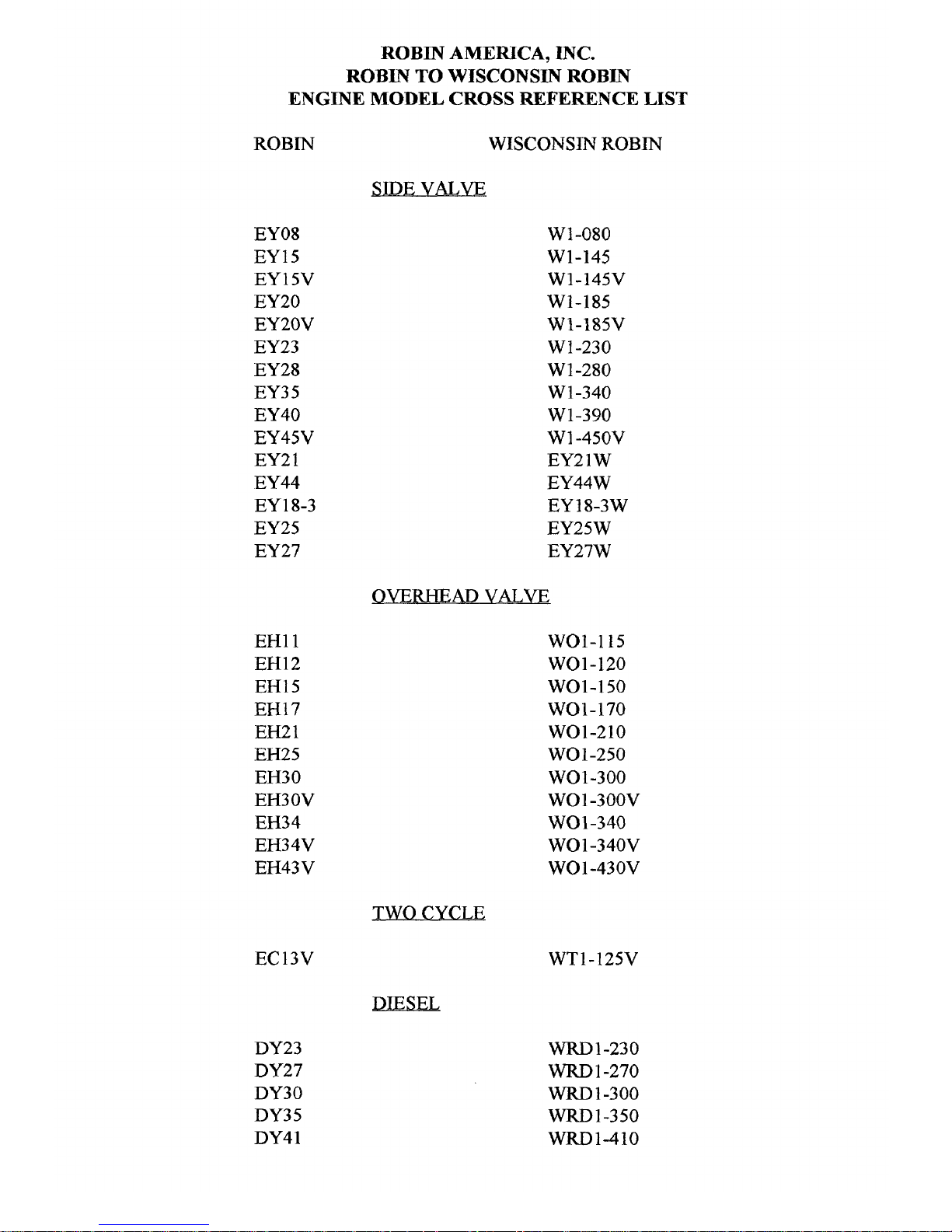
ROBIN AMERICA,
INC.
ROBIN
TO
WISCONSIN
ROBIN
ENGINE
MODEL
CROSS
REFERENCE
LIST
ROBIN
EY08
EY15
EY 15V
EY20
EY20V
EY23
EY28
EY35
EY40
EY45V
EY2 1
EY44
EY 1 8-3
EY25
EY 27
EHll
EH12
EH15
EH17
EH21
EH25
EH3
0
EH3 OV
EH34
EH3 4V
EH43V
EC13V
DY23
DY27
DY30
DY3
5
DY4
1
WISCONSIN
ROBIN
-
Wf-080
W1-145
W1-145V
W1-185
W1-185V
W 1-230
W
1-280
W 1-340
W1-390
W
1
-450V
EY21W
EY44W
EY25W
EY27W
EY 18-3 W
-
wo1-115
wo1-120
WO1-150
WO1-170
wo1-210
wo1-250
WO
1-300
WO 1 -300v
WO
1
-340
WO 1 -340V
WQ 1
-430V
TWO
CYCLE
WT1-125V
DlESEL
WRD1-230
WRD
1
-270
WRD
1-300
WRD1-350
WRD1-410
1
Page 3
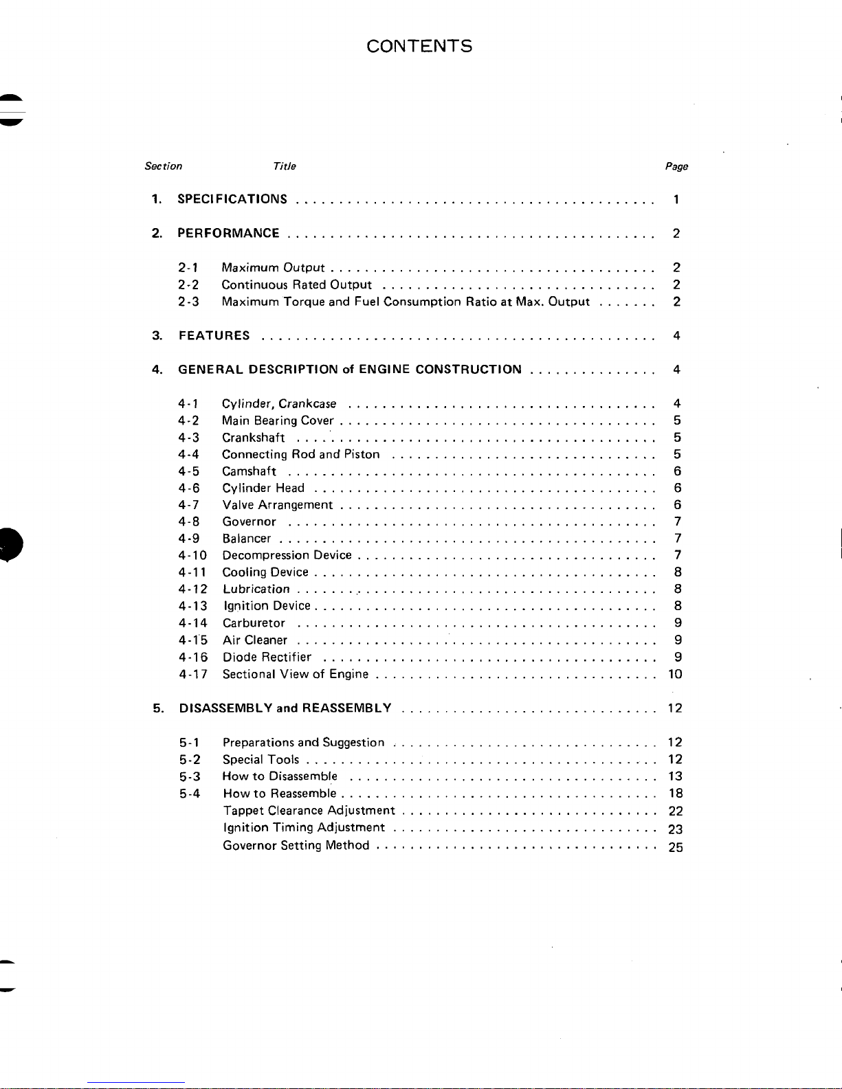
.
See
tion
1
.
SPECIFICATIONS
2
.
PERFORMANCE
CONTENTS
Title
..........................................
...........................................
Page
1
2
2-1
2-2
2-3
3
.
FEATURES
4
.
GENERAL DESCRIPTION
44-2
4-3
4-4
4-5
4-6
4-7
4-8
4
4-10
4-1
4-12
4-13
4-14
4
4-16
4-17
Maximum Output
Continuous Rated Output
Maximum Torque and Fuel Consumption Ratio
..............................................
1
Cylinder. Crankcase
Main Bearing Cover
Crankshaft
Connecting Rod and Piston
Camshaft
Cylinder Head
Valve Arrangement
Governor
Balancer
-9
Decompression Device
Cooling Device
1
Lubrication
Ignition Device
Carburetor
Air Cleaner
.
1.5
Diode Rectifier
Sectional View of Engine
......................................
................................
at
of
ENGINE CONSTRUCTION
Max . Output
...............
.......
....................................
.....................................
..........................................
...............................
...........................................
........................................
.....................................
...........................................
............................................
...................................
........................................
...........................................
........................................
..........................................
..........................................
.......................................
.................................
2
2
2
4
4
4
5
5
5
6
6
6
7
7
7
8
8
8
9
9
9
10
5 .
DISASSEMBLY
5-1
5-2
5-3
5-4
Preparations and Suggestion
Special
How
How
Tappet Clearance Adjustment
Ignition Timing Adjustment
Governor Setting Method
and
Tools
to Disassemble
to Reassemble
REASSEMBLY
..............................
...............................
.........................................
....................................
.....................................
..............................
...............................
.................................
12
12
12
13
18
22
23
25
Page 4

See rion Title
6
.
CARBURETOR
............................................
Page
26
6-1 Operation and Construction
6-2 Disassembly and Reassembly
7
.
BREAK-IN OPERATION
8
.
ROBIN SOLID STATE IGNITION ENGINE (OPTION)
8-1 Features
8-2 Basic Circuit and Operating Theory
8-3 Checking
8-4 Measuring Resistances
9
.
TROUBLE SHOOTING.
9-1 Starting Difficulties
9-2 Engine Misfires
9-3 Enginestops
9-4 Engine Overheat
9-5 Engine Knocks
9-6 Engine Backfires through Carburetor
10
.
INSTALLATION
10-1 Installing
10-2 Ventilation
10-3 Exhaust Gas Discharge
10-4
10-5 Power Transmission to Driven Machines
10-6 Wiring
Fuelsystem
............................................
S.S.I.
...........................................
............................................
.............................................
of
REASSEMBLED ENGINE
Unit with Tester
......................................
..................................... 30
........................................
.........................................
.......................................
........................................
..........................................
.........................................
...............................
..............................
of
Exciter Coil and Pulser Coil
...................................
.................
.................
of
S.S.
I . System
............
...............
:
...............
..............
.........................
.......................
26
27
28
29
29
29
29
29
30
31
31
31
32
32
33
33
33
33
33
34
34
11
.
CHECKS
12
.
TABLE
13
.
MAINTENANCE
13-1 Daily and Maintenance
13-2 Every 20 Hours Checks and Maintenance
13-3 Every
13-4 Every 100
13-5 Everv
13-6 Every 1000 Hours (Yearly) Checks and Maintenance
13-7 Preparation for Long Abeyance
and
CORRECTIONS
of
CORRECTION STANDARDS
and
STORING
..................................
.................................
..................................
50
Hours (10 days) Checks and Maintenance
-
200 Hours (Monthly) Checks and Maintenance
500-
600
Hours (Semiannual) Checks and Maintenance
.............................
...........................
......................
................
..........
........
...............
37
38
43
43
43
43
43
44
44
44
Page 5
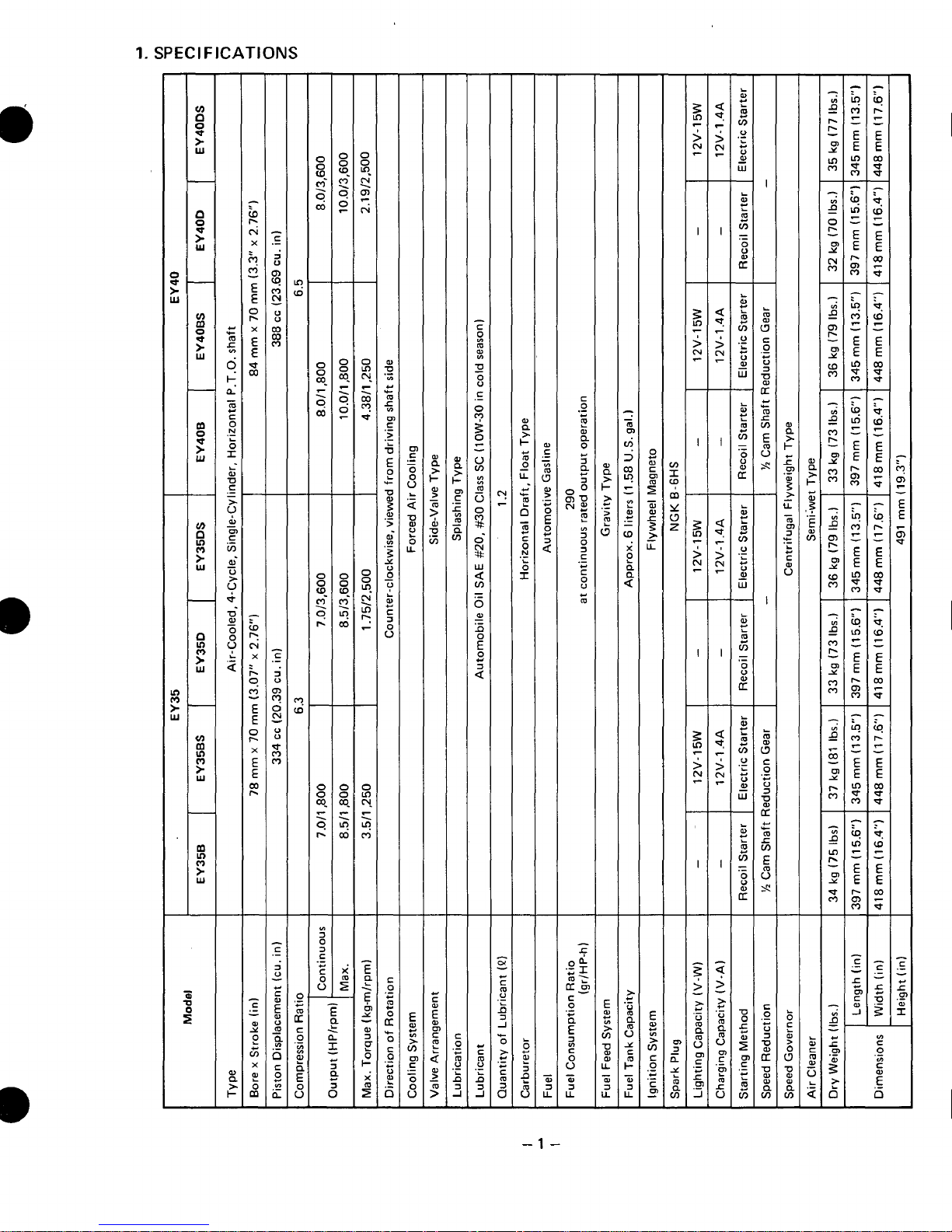
1.
SPECIFICATIONS
w
i
-1-
Page 6
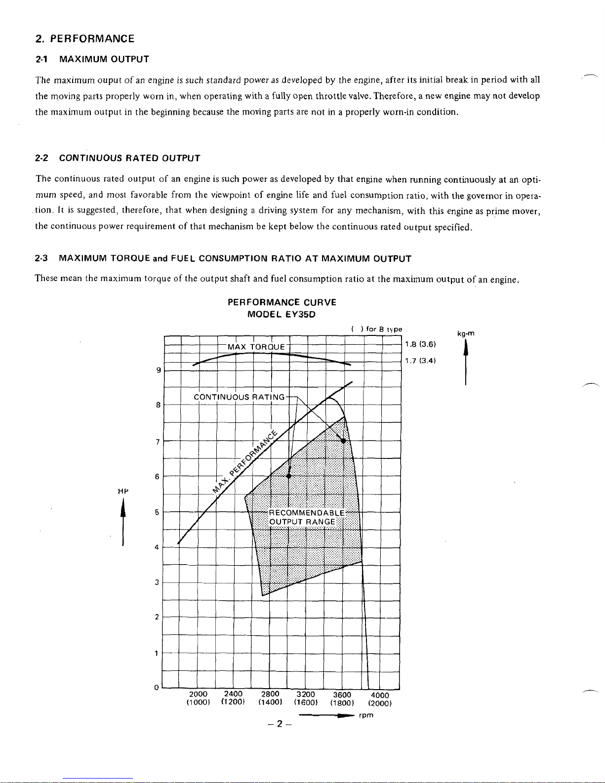
2.
PERFORMANCE
2-1
MAXIMUM
OUTPUT
The maximum ouput
of
an engine
is
such
standard power
as
developed by the engine, after its initial break in period with
all
the m,oving parts properly worn in, when operating with a fully open throttle valve. Therefore, a new engine may not develop
the maximum output
in
the
beginning because the moving
parts
are not in a properly worn-in condition.
-
rpm
-2-
Page 7
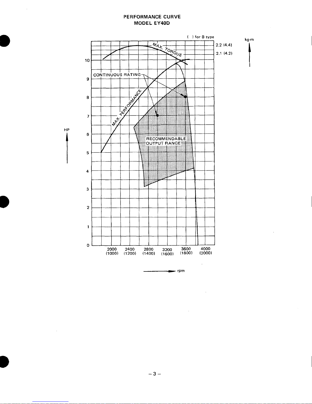
PERFORMANCE
CURVE
MODEL EY40D
kg-m
2.2
(4.4)
2.1
(4.2)
t
10
9
8
7
HP
I
6
5
4
3
2
1
0
-3-
Page 8
3.
FEATURES
Small
in
size, light in weight
The cylinder and crankcase are
reduced as much as possible
Quiet
operation with
low
Intake and exhaust noises are reduced by use
chine noise is reduced by selection
up
to
a quiet engine. Vibration
of
a timing balancer and optimum balance factor.
Easy
to start
of
for
easy mounting.
level
of
vibration
is
a one-piece aluminum diecast structure, which
of
a newly designed muffler having glass wool and a cyclone cleaner. Ma-
of
a suitable cam shaft profile and optimum clearances
also reduced
to
a low level by weight reduction
is
light in weight. The dimensions are
for
inner parts.
of
reciprocating parts, and selection
These engines can easily be started because they employ an automatic decompression device and a newly designed recoil starter.
of
Wide range
These models are available in various types
for
application to various kinds of machines. The engines have two
in any desired direction. Various optional parts are
adaptability
of
output shafts and also a type (Type
oil
drain ports, and their recoil starter can be pulled
also
available. All these combine
B)
with a built-in
to
increase adaptability to machines.
1
/2
reduction gear
Durable, reliable and safe
A
liner
of
special cast iron, hard-chrome-plate piston rings, forged rod, etc. are used to make these engines as reliable
and durable as the preceding models
of
the
EY
Series. Safety devices are also incorporated to assured added safety.
All
ths
adds
4.
GENERAL DESCRIPTION
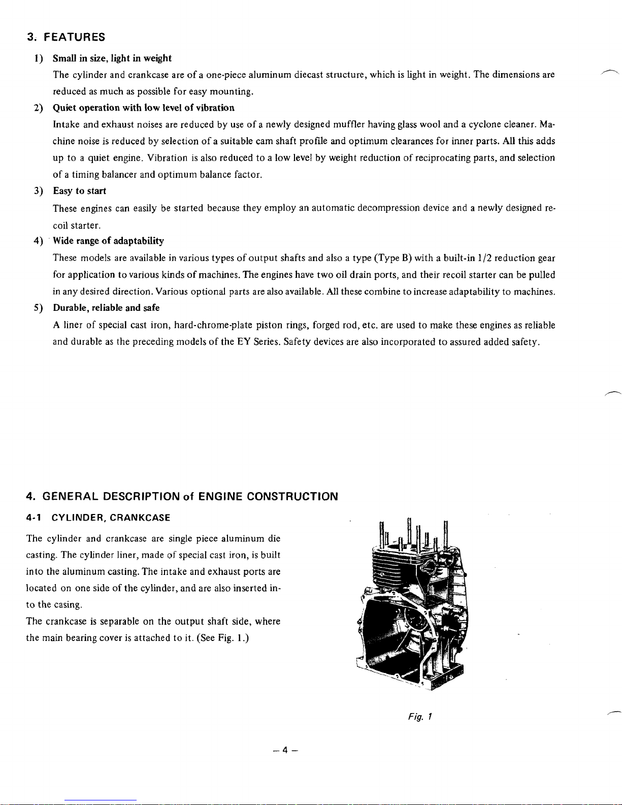
4-1
CYLINDER,
CRANKCASE
of
ENGINE CONSTRUCTION
The cylinder and crankcase are single piece aluminum die
casting. The cylinder liner, made
of
special cast iron, is built
into the aluminum casting. The intake and exhaust ports are
located on one side
to
the casing.
The crankcase is separable
the main bearing cover is attached to it. (See Fig.
of
the cylinder, and are also inserted in-
on
the output shaft side, where
1
.)
-4-
Fig.
1
Page 9
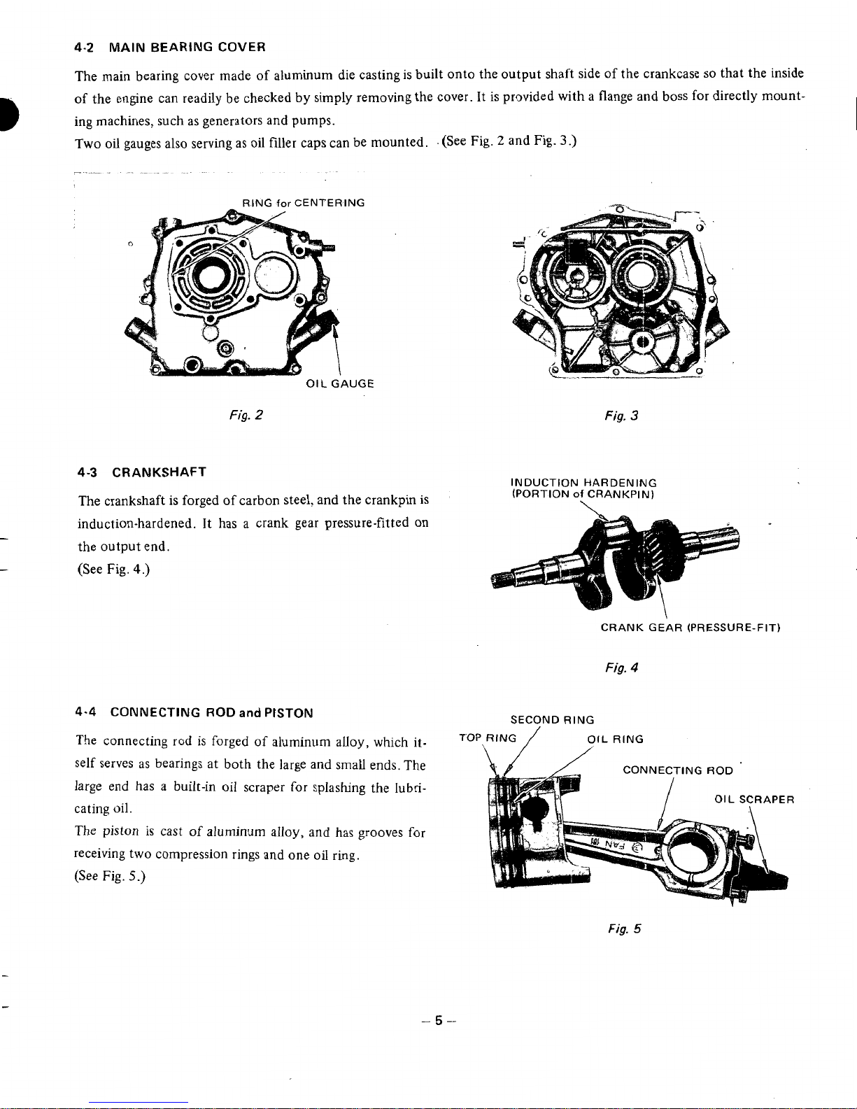
4-2
MAIN
BEARING COVER
B
The main bearing cover made of aluminum die casting is built onto the output shaft side of the crankcase
so
that the inside
of the engine can readily be checked by simply removing the cover. It is provided with a flange and boss for directly mount-
ing machines, such as generators and pumps.
Two
oil
gauges also serving as oil filler caps can be mounted. . (See Fig. 2 and Fig.
3
.)
RING
for
CENTERING
OIL
GAUGE
Fig.
2
Fig.
3
4-3
CRANKSHAFT
INDUCTION HARDENING
(PORTION
of
CRANKPIN)
The crankshaft
is
forged
of
carbon steel, and the crankpin
is
induction-hardened. It has a crank gear pressure-fitted on
the output end.
-
-
(See Fig.
4.)
CRANK GEAR (PRESSURE-FIT)
Fig.
4
4-4
CONNECTING
ROD
and
PISTON
The
connecting
rod
is
forged
of
aluminum alloy, which it-
self serves as bearings at both the large and small ends. The
large end has
a
built-in
oil
scraper
for
splashng the
lubri-
cating
oil.
The
piston
is cast
of
aluminum alloy, and has grooves
for
receiving two compression rings and one
oil
ring.
(See
Fig.
5.)
SECOND
RING
Fig.
5
-5-
Page 10
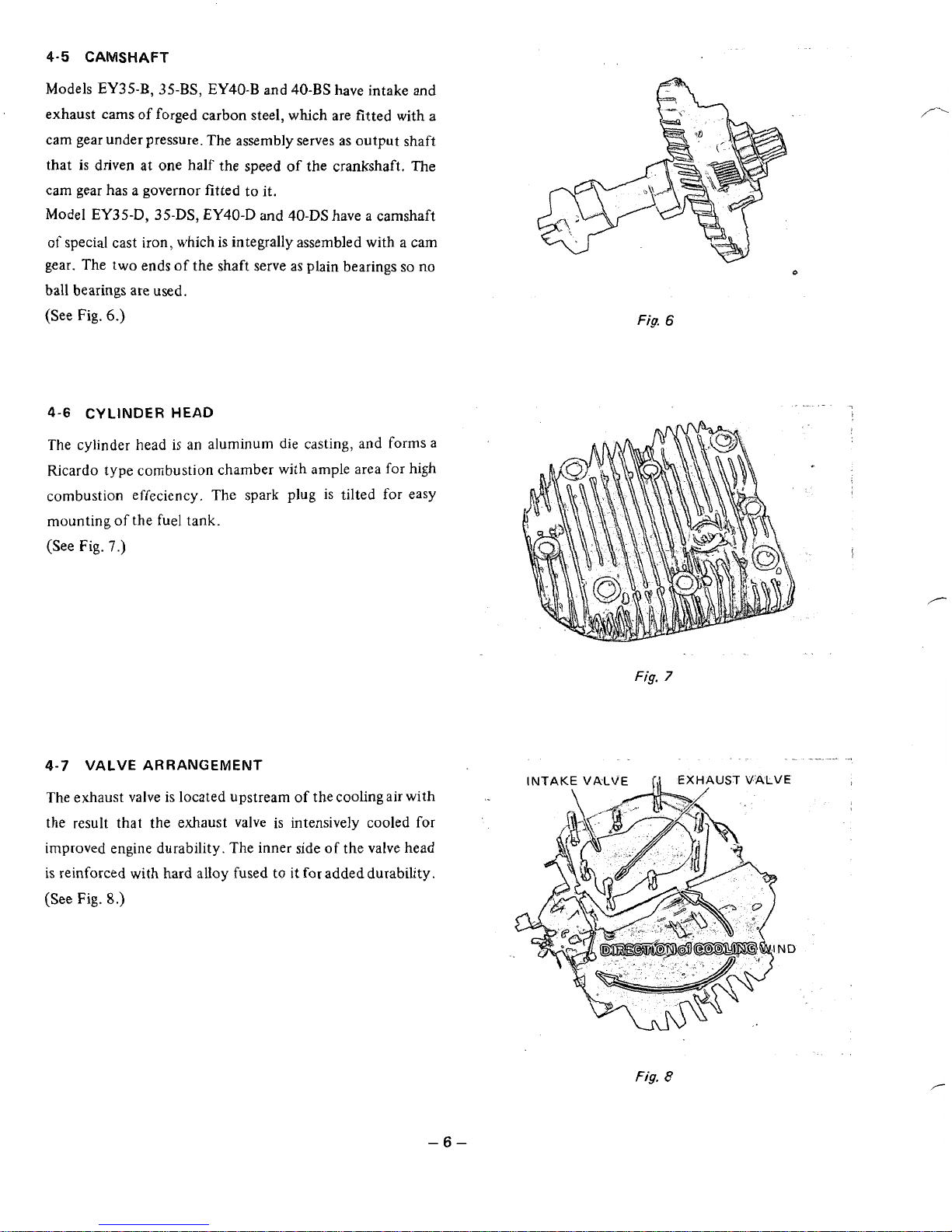
4-5
CAMSHAFT
Models
EY3S-B,
3S-BS,
EY40-B
and
40-BS
have intake
and
exhaust cams
of
forged carbon steel, which are fitted with
a
cam gear under pressure. The assembly serves as output shaft
that
is
driven at one
half
the speed of the crankshaft.
The
cam gear has a governor fitted
to
it.
Model EY35-D,
35-DS,
EY40-D
and
40-DS
have a camshaft
of
special cast iron, which is integrally assembled with a cam
gear. The two ends of the shaft serve as plain bearings
so
no
ball bearings are used.
(See
Fig.
6.)
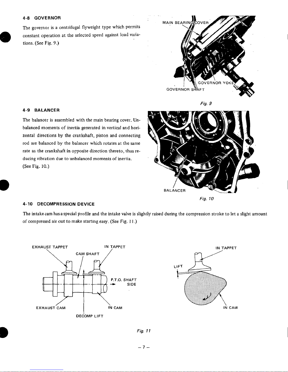
4-6
CYLINDER HEAD
The cylinder head
is
an
aluminum
die
casting,
and
forms a
Ricardo type combustion chamber with ample area
for
high
combustion effeciency. The spark plug is tilted for easy
mounting of the fuel tank.
(See
Fig.
7.)
0
Fig.
6
Fig.
7
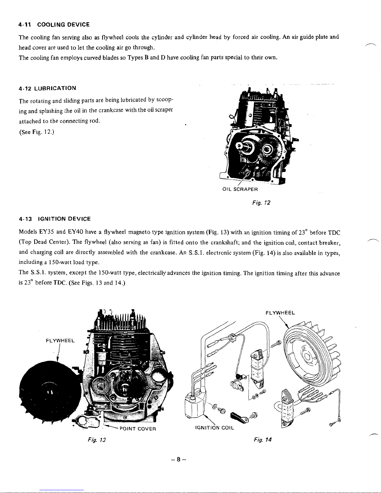
4-7
VALVE ARRANGEMENT
.
"
. ".
.._
_.
The exhaust valve is located upstream of the cooling air with
the
result that the exhaust valve is intensively cooled
for
improved engine durability. The inner side
of
the valve head
is reinforced with hard alloy fused
to
it
for
added durability.
(See
Fig.
8.)
Fig.
8
-6-
Page 11
4-8
GOVERNOR
The governor is a centrifugal flyweight type which permits
constant operation
at
the selected speed against load varia-
tions. (See
Fig.
9.)
4-9
BALANCER
The balancer is assembled with the main bearing cover. Unbalanced moments
of
inertia generated in vertical and horizontal directions by the crankshaft, piston and connecting
rod are balanced by the balancer whxh rotates at the same
rate as the crankshaft in opposite direction thereto, thus reducing vibration
due
to unbalanced moments
of
inertia.
(See
Fig.
10.)
4-10
DECOMPRESSION DEVICE
The intake cam has a special profile and the intake valve is sligh
of
compressed air out to make starting easy. (See
Fig.
11
.)
EXHAUST TAPPET
IN
TAPPET
'.O.
EXHAUST-CAM
DECOMP
LIFT
SHAFT
SIDE
Fig.
9
Fig.
10
.tly raised during the compression stroke to let a slight amou
IN
TAPPET
IN
CAM
Fig.
I
1
-7-
Page 12
4-11
COOLING
DEVICE
The cooling fan serving also
as
flywheel cools the cylinder and cylinder head by forced air cooling.
An
air guide plate and
head cover are used to let the cooling air
go
through.
The cooling fan employs curved blades
so
Types B and D have cooling
fan
parts special to their own.
".
.
4-12
LUBRICATION
The rotating and sliding parts are being lubricated
by
scoop-
ing and splashing the oil in the crankcase with the
oil
scraper
attached to the connecting rod.
(See
Fig.
12.)
OIL
SCRAPER
Fig.
72
4-13 IGNITION
DEVICE
Models EY35 and
EY40
have a flywheel magneto type ignition system
(Fig.
13) with
an
ignition timing of 23" before TDC
(Top
Dead Center). The flywheel
(also
serving
as
fan) is fitted onto the crankshaft; and the ignition coil, contact breaker,
and
charging coil are directly assembled with the crankcase.
An
S.S.I.
electronic system (Fig.
14)
is
also
available in types,
including
a
1
SO-watt load type.
The
S.S.I.
system, except the 150-watt type, electrically advances the ignition timing. The ignition timing after this advance
is 23" before
TDC.
(See Figs.
13
and
14.)
POINT
COVER
Fig.
13
FLYWHEEL
IGNITI~N
COIL
Fig.
14
Page 13
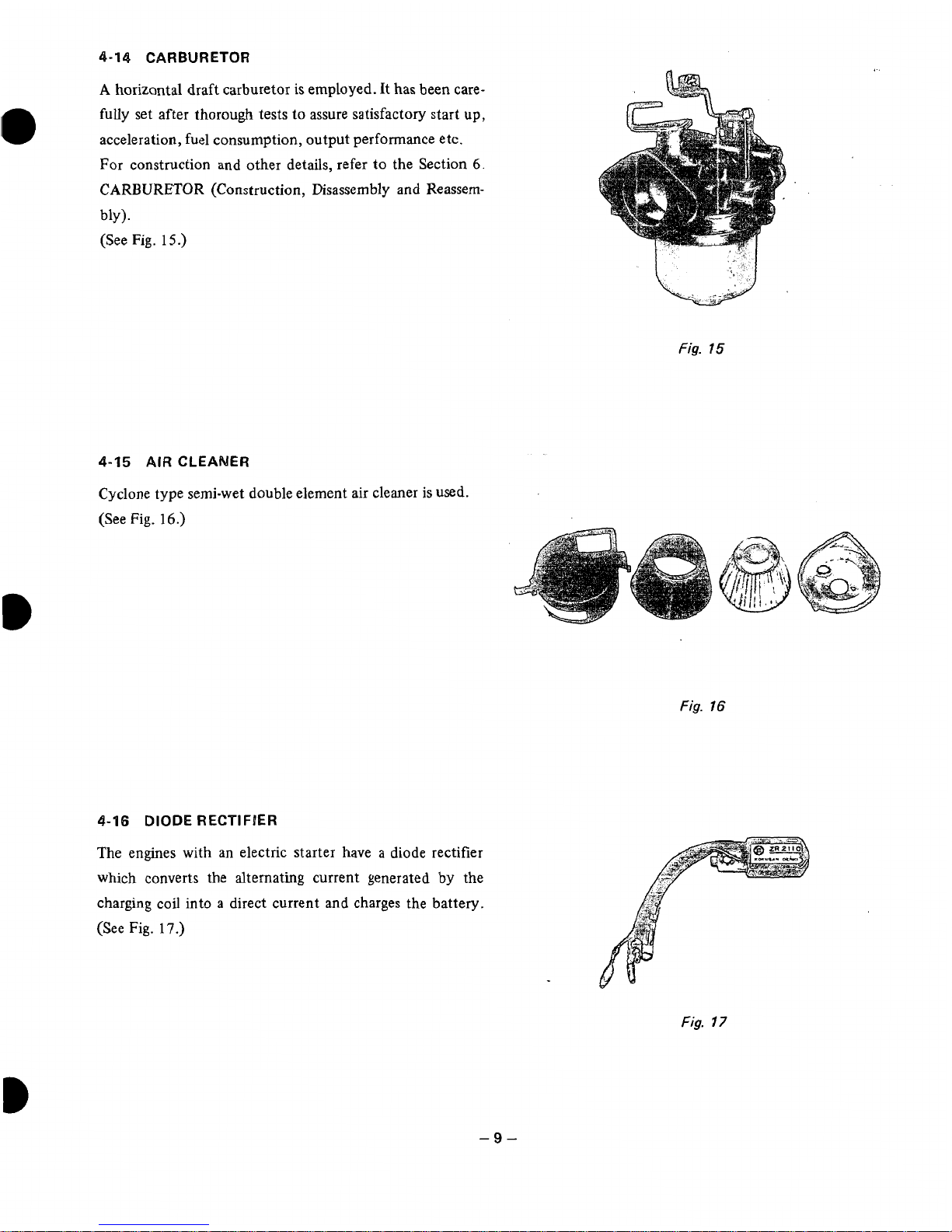
4-14
CARBURETOR
A
horizontal draft carburetor is employed.
It
has been care-
fully set after
thorough
tests to assure satisfactory start up,
acceleration, fuel consumption, output performance etc.
For construction and other details, refer
to
the Section
6.
CARBURETOR (Construction, Disassembly
and
Reassem-
blY
1.
(See Fig.
15.)
4-15
AIR
CLEANER
Cyclone type semi-wet double element air cleaner is used.
(See Fig.
16.)
4-16
DIODE
RECTIFIER
The engines with an electric starter have a diode rectifier
which converts the alternating current generated
by
the
charging coil into
a
direct current and charges the battery.
(See
Fig.
17.)
L,
Fig.
15
Fig.
16
Fig.
17
-9-
Page 14
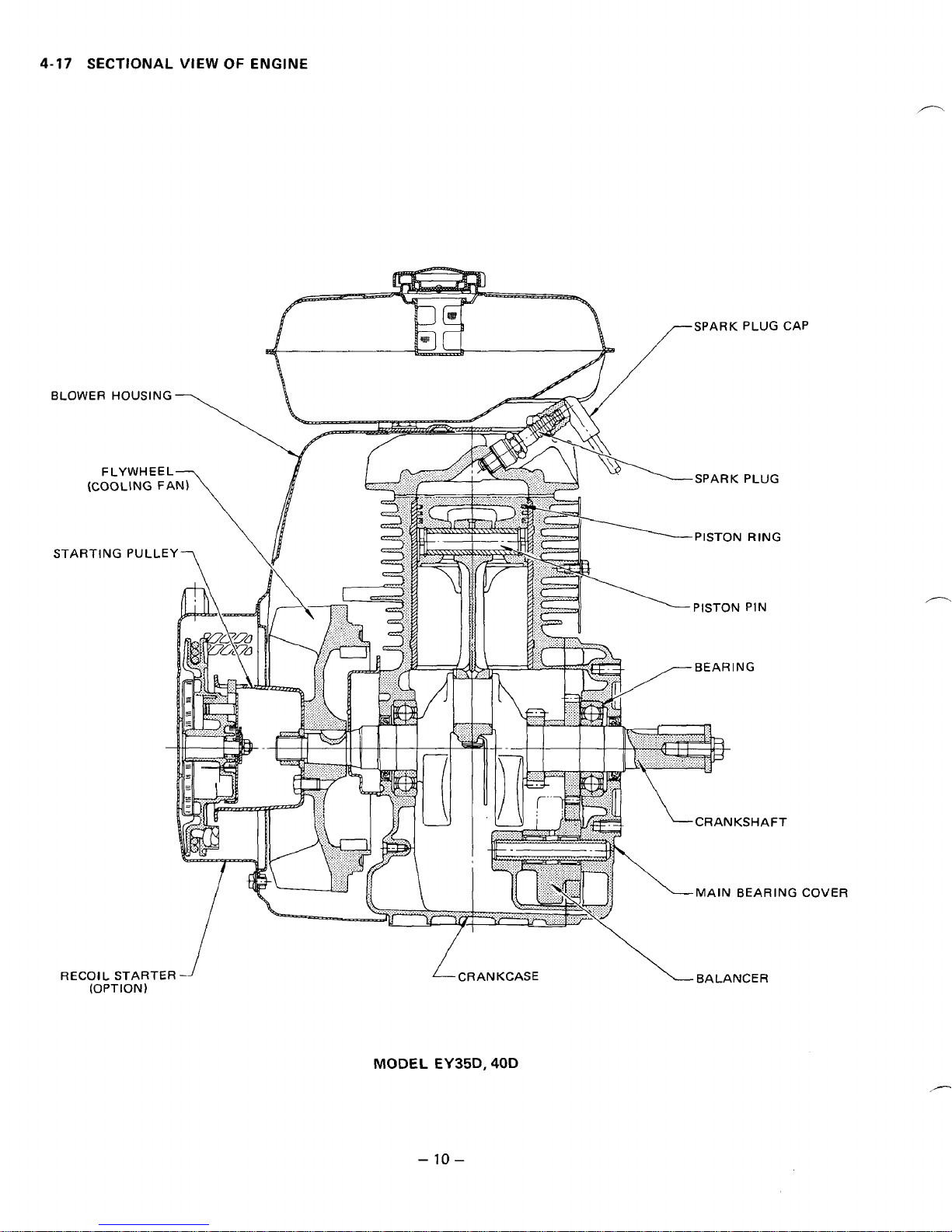
4-17
SECTIONAL VIEW
OF
ENGINE
/
RECOIL
STARTER
(OPTION)
-
I
MODEL
EY35D.
-
10
-
CRANKCASE
40D
BALANCER
Page 15
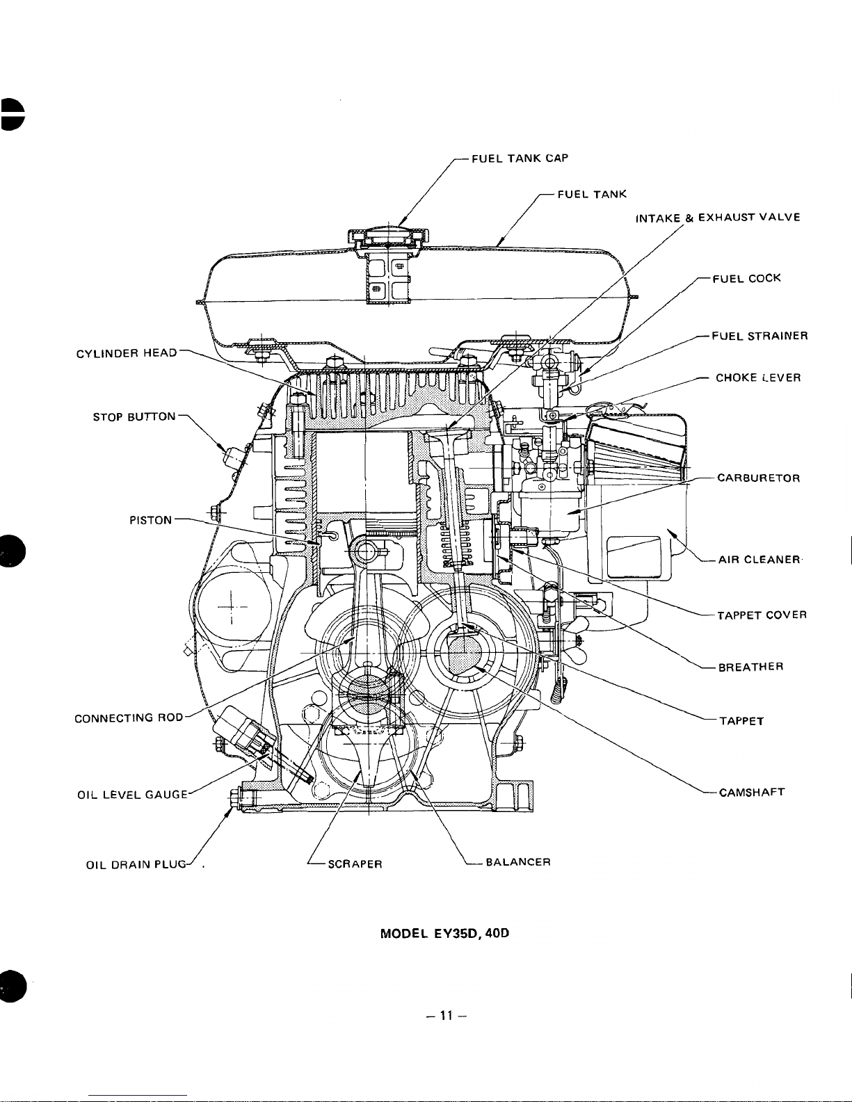
FUEL TANK CAP
INTAKE
&
EXHAUST VALVE
FUEL
COCK
BALANCER
MODEL EY35D,
40D
-
11
-
Page 16
5.
DISASSEMBLY
5-1
PREPARATIONS
1)
When disassembling the engine, remember well the locations
correctly.
2)
Have boxes ready to keep disassembled parts by group.
3)
To
prevent missing and misplacing, temporarily assemble each group
4)
Carefully handle disassembled parts, and clean them with washing oil.
5)
Use the correct
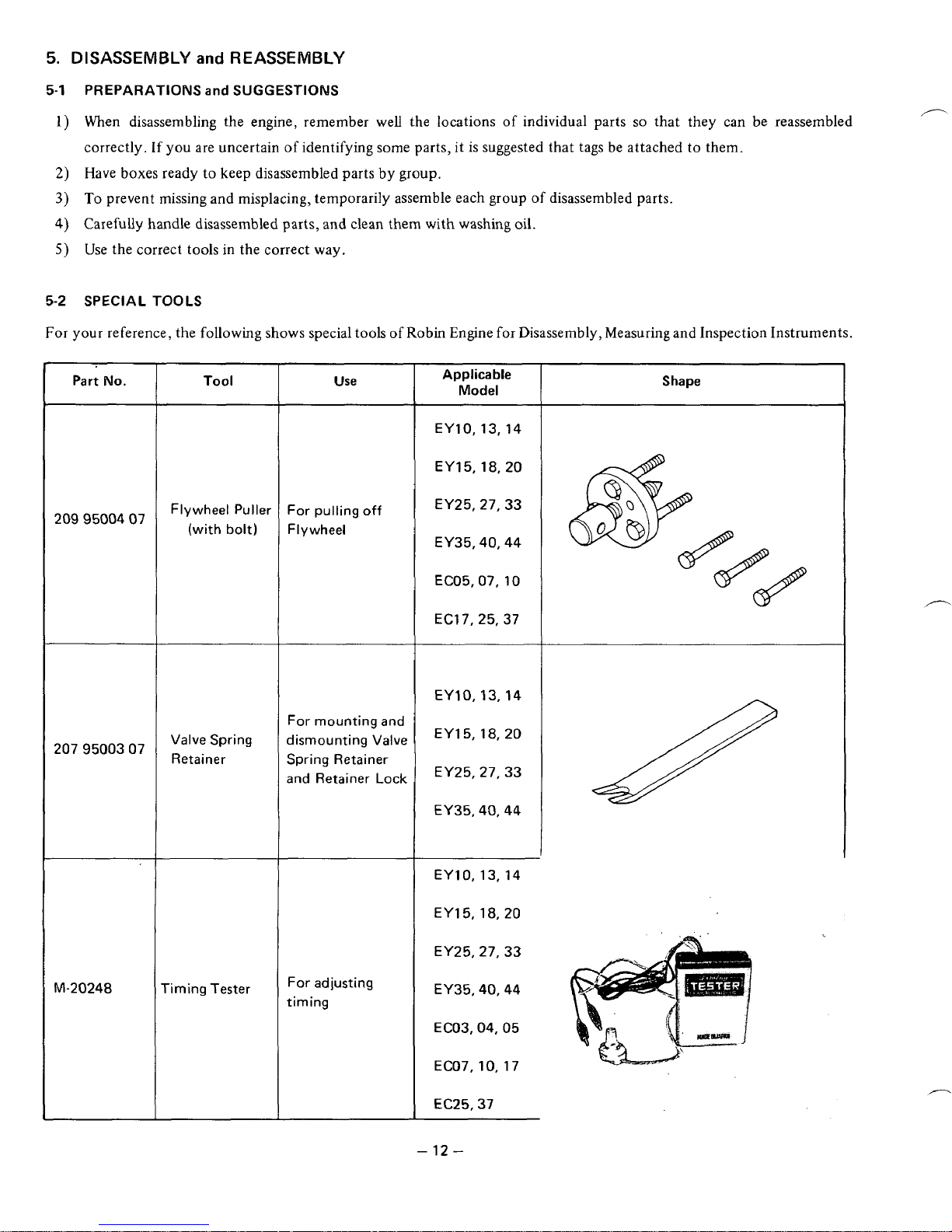
5-2
SPECIAL
For
your
reference, the following shows special tools
and
REASSEMBLY
and
SUGGESTIONS
If
you are uncertain
tools
in
the correct way,
TOOLS
of
identifying some parts, it
of
Robin Engine
of
individual parts
is
suggested that tags be attached to them.
of
disassembled parts.
for
Disassembly, Measuring and Inspection Instruments.
so
that they can be reassembled
Part
No.
2099500407
2079500307
Tool
Flywheel Puller
(with
bolt)
Valve
Spring
Retainer
~
Wse
For pulling
Flywheel
For mounting and
dismounting Valve
Spring Retainer
and Retainer
off
Lock
Applicable
Model
EY10,13,14
EY15,18,20
EY25,27,33
EY35,40,44
EC05,07,
ECf
EYIQ, 13.14
EY15,18,20
EY25,27,33
EY35,40,44
10
7,25,37
Shape
"20248
riming Tester
For adjusting
timing
EYlO, 13,14
EY15,18,20
EY25,27,33
EY35,40,44
EC03,04,05
EC07,10,17
EC25,37
-
12
-
,"-
Page 17

5-3
HOW
TO
DISASSEMBLE
*Length of the bolt indicates the length from the bolt head bottom surface to the threaded end.
Order
1
2
3
4
5
6
Item
Engine
Fuel tank
Tank bracket
Air cleaner
Muffler cover
Muffler
Procedures
Drain engine oil.
Drain plugs on both sides of the
case
(1) Close the strainer cock.
(2)
Move the fuel pipe clamp (on
strainer side) downward.
(3)
Remove the tank from tank
bracket.
Remove tank bracket.
(1)
Remove
element.
(2)
Remove choke knob.
(3)
Remove the bottom plate of
air cleaner.
Remove muffler cover.
(1)
Remove the flange portion
of the muffler.
(2)
Remove the muffler bracket.
air
cleaner cover and
Remarks
Be careful not to lose the
the gasket.
Bolts, nuts, etc. used
Flange bolt
8
mm
(No.2)
SpI-ing washer
10
mm flange nut
(tightened together with
cylinder head)
Swivel
6
x
12 mm flange bolt
. .
.
6
x
8
(5T) Flange bolt
*
.
.
8
mm brass nut
8
x
16
.
. .
nut
. .
.4
pcs.
.
.
.4
pcs.
.
.
.4
2
pcs.
4
pcs.
. . .
2
pcs.
(ST) Bolt & washer
2
pcs., Washer
. . .
pcs.
1
pce
Carburetor
7
Governor
8
lever
Remove the carburetor.
Remove the governor lever.
Be careful
etc.
Joint sheet, insulator, and
then paper packing, in ths
order from the engine side
Be careful
of the governor spring.
of
the packing
of
the position
6
mm nut
Spring washer
Washer
6
mm special nut.
Washer
6
x
25
.
. .
. . .
(7T)
. .
.2
2 pcs.
1 pce.
bolt
pcs.
.
.
.
2
.
. . .
pcs.
,
1
1
pce.
pce.
Fig.
-
13
18
-
Page 18

I
I
I
I
I
Order
Speed control
9
Bolts,
nuts,
etc.
used
Remarks
Procedures
Item
Circle clip
. .
.
1
pce.
Remember the assembling Disassemble.
order
of
component parts.
(See Fig.
19.)
8
mm butterfly nut.
. .
1
pce.
-
Order
10
11
Item
Operation
case
Electric
starter
h
Fig.
19
(1)
Disconnect the high voltage
wire connecting the electric
starter to the magnetic switch
on the side
of
the switch.
(2)
Remove the bolts.
(3
pcs.)
Remove electric starter.
Remarks
Bolts, nuts, etc. used
(See Fig.
20.)
Two
of
the three
6 x 8
(5T)
flange bolts tighten the
cylinder buffle and fan cover
together.
8
x
30
reamer bolt
. . .
2
pcs.
Spring washer
.
. .
2
pcs.
Washer
.
.
.2
pcs.
Fig.
20
-
14-
Page 19

Order
-
12
-
13
Starting pulley
Flywheel
14
-
Item
Fan cover
I
(1)
(2)
(3)
Remove starting pulley.
I
Remove flywheel. Be sure
Procedures
Remove the fan cover.
Remove the head cover.
Remove the cylinder buffle.
I
Removable by loosening
bolts
wheel puller.
crankshaft.
Fig.
to
Remarks
21
.)
use the fly-
Do
I
Bolts,
nuts,
6 x 8
flange bolt
6
x
8
flange bolt
8
x
12
(ST)
18
mm nut
not Spring washer
bolt
. . .
etc.
1
.
.
. .
. . .
. . .
pce.
.
1
used
.
6
pcs.
1
pce.
3
pcs. (See
pce.
Fig.
21
Fig.
22
b
--
15
-
Page 20

Order
15
-
16
Item
Electric
devices
Cylinder head
Procedures
(1)
Remove point cover.
(2)
Remove contact breaker.
(3)
Remove ignition coil and condenser.
(1)
Remove spark plug.
(2) Remove cylinder head.
Remarks
Be careful
lead connecting direction.
before disassembly.
of
the primary
Bolts,
nuts,
etc. used
4
x
12
screw
and
. .
.
2
pcs.
4
x
8
screw and washer
. . .
1
pce.
6
x
25
screw and washer Remove the lighting coil
. .
.
2
pcs.
10 mm flange nut
washer
. .
.8
pcs.
I
1
17
Tappet cover
(breather
plate)
Intake and
exhaust valves
Remove Tappet cover.
(1)
Remove intake valve.
(2)
Remove exhaust valve.
Be
valve mounting position
and the order
ing
(See
Intake and exhaust valve
springs, retainers and retainer locks are common;
but be sure to set up them
on
the original valves.
(See Fig. 24.)
Of
packings.
Fig.
23.)
the
breather
of
assembl-
I
6
x
14 flange
bolt
. . .
I
Use valve spring retainers.
2
pcs.
I
Fig.
23
Fig.
24
-
16-
Page 21

Irder
I
Item
19
Main bearing
cover
~
20
Camshaft
I
Procedures
~~~ ~ ~ ~~~~~
(1)
Set the piston to the TDC, re-
move blind plug
in
the lower
part
of
the front side of bear-
ing cover, and insert the
4
mm
stick.
(2)
Remove bolts.
(3)
Strike the side of main bearing cover with a plastic hammer or the like to remove the
cover from crankcase.
Remove camshaft.
r
Order
Intake/ex-
2
1
Item
haust tappets
22
Connecting
rod and piston
23
Crankshaft
Remarks
I
Bolts, nuts, etc. used
(See Fig.
25.)
In case of Type
B,
be careful not to remove camshaft
together.
*Crankshaft and camshaft
have adjusting
shims.
(TY
Pe
B)
6
x
8
flange bolt
. .
.
1
pce.
Gasket (aluminium)
.
.
.
1
pce.
8
x
35
(7T)
set bolt
. .
.
8
pcs.
Camshaft can easily be
pulled by hand. Be careful not to let the tappets
drop.
1
Fig.
25
Fig.
26
Procedures
Bolts, nuts, etc. used
Remarks
~ ~~
Remove intake/exhaust tappets. Intake and exhaust tap-
pets are the same, but be
sure to intall them in their
original positions because
1
of
the valve clearance.
~~
(1)
Return the lock washer.
(2)
Remove bolts.
(3)
Push
the piston up out
of
the top of cylinder.
8 x 46
reamer bolt
.
~
.2
pcs.
I
Hold crankshaft with hand. and
I
Be careful of
oil
seal on
I
gently tap the flywheel end. the crankcase magneto
side.
-
17
-
Page 22

5-4
HOW
TO
REASSEMBLE
5-4-1
PRECAUTION IN REASSEMBLY
Every and each part should be cleaned thoroughly. Especially, pay utmost care and attention to the cleanliness of the
piston, cylinder, crankshaft, connecting rod and bearings.
Scrape completely off carbons from the cylinder head and the upper part of the piston; especially the carbon adhered
in the groove of the piston ring should be carefully and completely taken out.
Carefully check the lip portion
of
every oil seal.
If
faulty one is found, replace it without any hesitation.
Apply enough
oil
to the lip portion
of
the
oil
seal when reassembling.
Replace all the gaskets with new ones.
Replace the key, pin, bolt, nuts, etc. with new one, if necessary.
Whenever tightening torque is specified, conform
to
the specified figures.
Apply oil
to
the revolutionary parts and friction surfaces, when reassembling.
Check and adjust the clearances
of
various portions and then reassemble.
When some main portions are assembled in the course
of
reassembling, turn or move the gadgets by hand and pay at-
tention to the frictional noise and resistance.
5-4-2
MEASURING CRANKCASE and CRANKSHAFT
Bore the cylinder or take other steps as necessary
to
meet
the following specifications before reassembling.
EY35
E
Y40
I
W
(Crankshaft
Pin
Width)
I
29
+0.1
0
Bore
Piston Outside Diameter (In Skirt Thrust Direction)
78
dia.
40.019
I
84
dia.
,,
+0.022
I
Piston
to
Cylinder
at
Piston Skirt
Thrust
Face
I
0.049L
-
0.1
08L
1
0.049L - 0.1
11
L
Piston Ring Gap (Top Ring - Second Ring)
I
Piston Ring Side Clearance in Grooves
(Top Ring
-
Second Ring)
Clearance between Connecting
Rod Large End and Piston Pin
and
Outside
Diameter
Clearance between Inside
Side
Clearance
0.1
L
-
0.3L
0.05
-
0.09
Clearance between Connection
Rod Small End and Piston Pin
Clearance between Piston Pin and Pinston Pin Hole
0.070
-
0.102L
0.020L - 0.042L
0.1
L
-
0.4L
0.1
1T - 0.01 1 L
r'
L:
LOOSE
Fig.
27
-
18
-
Page 23

5-4-3
ASSEMBLING
1)
Place the tappets into the crankcase.
NOTE:
The intake and exhaust tappets are the same,
but mark them differently when disassembling because of different
fit
the tappets beforehand.
ORDER
them into their origianl place. Apply oil to
Assemble the crankshaft
time.
NOTE:
3)
Assemble the connecting
NOTE:
CAUTION:
4)
Fit
NOTE:
NOTE:
The same timing mark
side
is
punched on the crankshaft gear inward
of the balancer gear
match these timing marks on the crankshaft
and camshaft sides before installing these
shafts in the crankcase.
The piston
must be marked with
direction indicated.
When inserting the piston pin and fitting the clip on, be careful not to damage the piston surface.
the
piston rings on the piston.
Each
that
The oil ring consists
spacer, lower rail, and upper rail.
in this order. The open ends of each ring must
be
as
is
not offset
piston ring must be installed upside
is,
the puched mark
shown in Fig.
and
PRECAUTIONS
..
valve
clearances; and
and
camshaft at the same
as
on the crankshaft
as
shown in Fig.
rod
with
the piston.
so
a
new piston does not require to
a
sign indicating its direction when disassembling
28.
So,
up,
at
the open ends up.
of
three parts, that is,
Fit
them on
a
UPPER RAIL LOWER
29.
TIMING MARK ON CAMSHAFT SIDE
(Punch
2
pcskl
TIMING
(Punch
be
MARK ON
1
pce.)
installed in a specific direction, but a used piston
CRANKSHA??
Fig.
28
so
that
it
can be assembled again in the
THRUST SIDE
RAIL
Fig.
30
-
19-
Fig.
29
ASSEMBLY TYPE
Fig.
3
1
OIL
RING
Page 24

5)
Assemble the piston
and
connecting
rod
that were
readied in Steps
3)
and
4).
NOTE:
The symbol @FAN mark on the connecting
rod must be on the magneto side.
NOTE:
Be careful
of
the match mark on the cap. If
the match mark
is
at
the correct position, the
oil scraper should be on the main bearing
cov-
er side.
NOTE:
Tightening bolt
. . .
. . . .
8
x
46
(special)
Tightening torque
. . .
250
-
300
kg-cm
Use new lock washers, and bend their edges
securely.
Install
the
main
bearing
cover.
NOTE:
If
the oil
seal
is
damaged when the governor
yoke
is
installed, replace
it
with a new one.
NOTE:
Adjust the side clearance to anywhere be-
tween
0.05
and
0.2
mm. The side clearance
can be measured by measuring sizes
A
and
B
as
shown in
Fig.
33,
and assume that the thick-
ness
of
packing
C
is
0.25
mm when tightened.
*
The side clearance can
also
be measured
as
shown in photos below. (Figs.
34
and
35)
~
MATCH
u__
Fig.
32
CRANKSHAFT SPACER
\
MAIN BEARING
BALANCER
Fig.
33
Fig.
34
-
20
-
Fig.
35
Page 25

NOTE:
7)
Install the intake
*
Intake
Check the main bearing cover joint for flaw,
and correct
Fit the governor
with new packing.
*
Move the piston up to TDC, insert the 4 mm
stick into the main bearing cover, and fasten the balancer
Tightening bolt
Tightening torque
*
Insert the blind plug
the balancer fixing hole with the aluminum
gasket, and check if the crankshaft srnooth-
ly
and
if
necessary.
sleeve
into
the
as
runs.
and
exhaust valves.
shown in Fig.
. . .
. . . .
.
.
.170
(6
x
8
8
x
-
190
flange
36.
35
bolt)
exhaust valve specifications are as
cam gear
(7T)
kg-cm
into
follows:
A.4
IF
Fig.
4O
36
VALVE
A-VALVE FACE ANGLE
6-SEAT ANGLE
C-GUIDE INSIDE DIA.
~~~~ ~ ~
D-VALVE STEM OUTSIDE DIA.
MAXIMUM ALLOWABLE
CLEARANCE 8ETWEEN
and
VALVE
GUIDE
C
and
CLEARANCE
INTAKE
INTAKE
D
Fig.
-21
37
-
EY35
+0.036
8dia.
dia.
-0.070
-0.090
0.030L
-
0.091
0.070L - 0.1
26L
GUIDE
E
Y40
L
Page 26

.TAPPET CLEARANCE ADJUSTMENT
Move the piston up to compression
the tappet clearance as
follows,
TDC,
and adjust
using a grinder or the
like.
Clearance (Models
EY35,
EY40
intake and exhaust):
0.13 - 0.1 7 mm when cold
*
Intake and exhaust valve installation
Apply oil to the valve stems, and install the valves
securely by using the special tool, valve spring re-
tainer and pliers. (See Fig.
39.)
After their installation, check the tappet clearance
again.
Fig.
38
8)
Install the breather plate and tappet cover.
NOTE:
9)
Install the cylinder head.
NOTE:
Be careful of the gasket installing order (See
Fig.
40.)
and breather valve position.
The breather
side.
6
x
14
Replace the head gasket with a new
10
mm flange nut
Tightening torque
valve
flange bolt
must be on the intake
..........
...........
...
340 - 390
Fig.
39
valve
2
pcs.
Fig.
40
one,
and tighten the nuts uniformly with the specified torque.
8
pa.
kg-cm
-
22
-
Page 27

10)
Electrical installation
*
Install the ignition coil
Screws:
*
Temporarily install the contact breaker.
Screw:
CAUTION:
*IGNITION TIMING ADJUSTMENT
Ignition timing
Point gap
Adjusting method
If
the point surfaces are rough, smoothen them. Hold
the top of the point cam on the crankshaft in contact
with the heel
contact breaker itself until the correct point gap is
tained. The ignition timing of the engine depends on
the point gap.
tion timing
.IGNITION TIMING
Use a timing tester, Part
Checking method
As
shown in Fig.
other lead to the crankcase, switch the timing tester on, and hold the earphone close to the ear. Slowly turn the flywheel
matches the
agree, repeat the above mentioned adjustment.
6
x
25
screw and washer
4
x
8
screw and washer
Be
careful
............
...............
of
the contact breaker, and move the
If
the gap is correctly adjusted, the igni-
will
be
43,
in
normal direction (clockwise for Type
M
mark on the case when the buzzer sounds, it
and
capacitor.
. .
2
...
1
of
the
location
of
23"
before TDC
.0.35
23"
before
CHECK
connect one of the leads
TDC.
N0.M-20248
pcs. each
pce. each
the
cord.
k0.05
mm
Fig. 4 1
ob-
Fig.
42
of
the timing tester to the primary wire of the ignition coil, and the
D,
or counterclockwise for Type
is
the correct ignition timing. If the two marks do not
B),
and if the mark on the flywheel
rKER
---"
FLYWHEEL
Fig.
43
-
23
-
Fig.
44
Page 28

*SPARK CHECK
*
Clean the point surfaces of
oil
with paper or the like, and temporarily install the flywheel.
*
Hold the high-voltage wire with hand
so
its end
is
about 5 mm away from the case,
and
turn the flywheel in normal
direction.
*
Check that a spark
is
generated when the M mark
on
the flywheel passes the M mark on the case.
*
Install the
point
cover.
4
x
12
screw and washer
......
2
PCS.
11) Install the flywheel.
NOTE:
Before installing the flywheef, clean the crankshaft and the tapered part of the flywheel of oil.
16mmnut
................
1 pce.
Spring washer
..............
1
pce.
Washer.
..................
1 pce.
Tightening torque
..
.800
-
1000
kg-cm
12) Install the starter pulley.
8 x 12
bolt
(ST)
............
3
pcs.
13) Install
the
fan
cover and head cover cylinder buffle.
NOTE:
Before installing the fan cover, first install
the
head cover
on
the cylinder head.
Also
install
the
muffler brack-
et
in
place
at
the same time.
6
x
8
flange bolt
............
7
pcs.'
14)
Install the recoil starter
NOTE:
Pulling direction may vary with machine make.
6
x
8
flange bolt
............
4
pcs.
15)
Install the carburetor.
NOTE:
Install
the carburetor with the joint sheet, insulator, and paper packing in this order.
6
mm nut
.................
2
pcs.
Spring washer
..............
2
pcs.
Washer.
..................
2
pcs.
16) Install the speed control
and
governor lever according
to the arrangement
of
parts
shown
in
Fig.
47.
Hook
the governor spring at the proper hole.
8
mm wing nut
.............
1
pce.
Clip..
...................
1
pce.
0
Fig.
45
-
24
-
Page 29

.GOVERNOR
*
Set the speed control lever to the high-speed position, and fasten it there with the wing nut. (The
governor spring
*
Check that the carburetor and throttle valve are
fully open.
*
Turn the governor shaft counterclockwise,
fasten the governor lever. (See Fig. 46.)
Install the starter motor.
8 x 30
Spring washer
Washer.
Install the operation case. (with the electric starter)
6 x 8
*
Two of the three flange bolts tighten the case together with the cylinder buffle and fan cover.
*
Properly wire as shown in the wiring diagrams (Pages
Install the muffler.
NOTE:
Install the muffler cover.
Install the
NOTE:
After mounting the cleaner bottom plate, install the choke knob, element retainer, element and cover
Install the tank bracket.
Install the fuel tank.
Connect the fuel pipe.
Clamp the pipe securely.
Supply 1.2 liter engine
The muffler gasket must be placed
8m brass nut
8
Washer.
6
Make sure that the tip of the breather pipe
SETTING METHOD
is
in.)
reamer bolt
...........
..............
..................
flange bolt (5T)
.........
...............
x
16
bolt (for bracket)
..................
x
8
flange bolt (5T)
air
cleaner.
6
x
12 flange bolt
10
mm flange nut
(also for cylinder head)
8
mm
No.2
nut
Spring washer
..............
oil.
.........
...........
...........
.............
in
.......
and
2
pcs.
2
PcS.
2
pes.
3
pcs.
34
and
35).
'the correct direction.
2 pcs.
2
pcs.
1
pce.
4
pcs.
out
of the tappet cover
2
pcs.
4
pcs.
4
pcs.
4
pcs.
Fig.
46
(Non-symmetric direction)
is
clear off the element retainer.
in
ths order.
-25
-
Page 30

6,
CARBURETOR
SPECIFICATION
I
Model
Main
Main
Pilot
Throttle Valve
Pilot Screw
1
(Return)
OPERATION and CONSTRUCTION
6
-1
No.
Jet
Air
Jet
Jet
I
EY35
#107.5
1
turn
E
I
Y40
BV26-20 BV26-19
2246230100 2236230100 Part
#112.5
$1.2 $1.5
#57.5 #55
#135 #150
PI
LOT
NEEDLE VALVE
FLOAT CHAMBER
A
FUEL
FLOAT
Fig.
-
W
26
48
-
Page 31

6-1
-1
FLOAT SYSTEM
The float chamber
is
located just below the carburetor body and, with a float and a needle valve, maintains a constant fuel
level during engine operation.
The fuel
flows
from the fuel tank into the float chamber through the needle valve. When the fuel rises to a specific level, the
float rises; and when its buoyancy and fuel pressure are balanced, the needle valve close to the shut off the fuel, thereby
keeping the fuel at the reference level.
6-1
-2
PI
LOT SYSTEM
The pilot system feeds the fuel
to
the engine during idling and low-speed operation.
The fuel is fed through the main jet to the pilot jet, where it is metered, and mixed with the air metered by the pilot air jet.
The fuel-air mixture
is
fed to the engine through the pilot outllet and the by-pass.
During engine idling, the fuel is mainly fed from the pilot outlet.
6-1-3
MAIN SYSTEM
The main system feeds the fuel to the engine during medium- and high-speed operation.
The fuel is metered by the main jet and fed to the main nozzle. The air metered by the main air jet is mixed with the fuel
through the bleed holes in the main nozzle, and the mixture is atomized out of the main bore. It is mixed again with the
air
taken through the air cleaner into an optimum fuel-air mixture, which is supplied to the engine.
6-1
-4
CHOKE
The choke is used for easy start in the cold season. When the recoil starter
is
pulled with a closed choke, the negative pres-
sure applied to the main nozzle increases and draws much fuel accordingly; thus easily start up the engine.
6-2
DISASSEMBLY
and
REASSEMBLY
Apart from mechanical failures, most of carburetor troubles are caused by an incorrect mixing ratio, which may arise mainly
due to a clogged up ah or fuel passage in jets, or fuel level variations. In order to assure proper flow of air and fuel, the car;
buretor must be kept clean at all times. The carburetor disassembly and reassembly procedures are as follows: (See Fig.
6-2-1
THROTTLE SYSTEM
1) Remove the Phdlips screw
2)
The spring
(5)
can be taken out by removing the throttle stop screw
*Be careful of the direction
(I)
and throttle valve
of
the throttle valve.
(2),
and pull
The circumference of the throttle valve is aslant. Install the valve
out
the throttle shaft
(4).
so
the punched mark on the valve can be seen on the
(3).
left.
''
6-2-2
6-2-3
CHOKE
I)
Remove the Phillips screw
2)
When reassembling the choke shaft, make sure that the cutout in the choke valve faces the main air jet.
PILOT SYSTEM
I)
Remove the pilot jet
2)
Remove pilot screw
3)
Reassembly
SYSTEM
(6)
and choke valve
(1
0),
using correct tool to avoid damage to it.
(1
1)
and spring
(1
2).
(7),
and pull out the choke shaft
(8).
Stop ring
(9)
can not be removed.
*Tighten the pilot jet securely. Otherwise, the fuel may leak, causing engine malfunction.
*If the tapered part of the pilot screw is out
of
shape, replace it with a new one.
49.)
-
27
-
Page 32

6-2-4
MAIN
SYSTEM
1)
Remove the bolt
(1
3)
and take out float chamber
body
(15).
2)
Remove the main jet
(1
7)
and
main
nozzle
(1
8),
using
correct tool to avoid damage to it,
3)
Reassembly
Fasten the main jet securely to the body. Otherwise,
the fuel may become
too
rich and cause engine mal-
function.
6-2
-5
FLOAT
SYSTEM
When removing the needle valve
(21)
and float
(20),
gently
tap the reverse side using the rod more slender than the
float pin
(19)
and remove because the float pin
is
calked to
the carburetor body.
*When cleaning the jets, use neither
a
drill
nor
a wire
(because of possible damage of the orifice which will
adversely affect fuel
flow).
Be sure to use compressed
air to blow them clean.
Fully tighten the pilot screw and then loosen
it
coun-
terclockwise by one turn for Model
EY35,
or one
turn and a
half
for Model
EY40.
When fully closing
the pilot screw, do not tighten it too hard. Otherwise,
the needle at the tip might become damaged.
Turn the throttle stop screw clockwise
to
a
normal
idling speed
of
1200
rpm.
Make a final adjustment when the engine is in normal
I
A
‘17
19
-18
Fig.
49
operating condition at normal temperature with the correct air cleaner mounted.
7.
BREAK-IN OPERATION
of
REASSEMBLED ENGINE
An
overhauled engine must be operated
at
low speed break-in the parts. A thorough break-in is indispensable particularly
when the cylinder, piston, piston rings or valves are replaced with new ones.
Thl
e
recommended break-in schedule is shown below.
LOAD
SPEED
TIME
EY35
EY
40
NO
LOAD
10
minutes
2,500
rprn
~
NO
LOAD
30
minutes
3,600
rpm
4.0
HP
3.5
HP
10
minutes
3,600
rprn
NO
LOAD
10
minutes
3,000
rpm
7.0
HP
I
8.0
HP
~
1
3,600
rpm
I
60
minutes
1
-
28
-
Page 33

8.
ROBIN
SOLID
STATE IGNITION ENGINE (OPTION)
8-1 FEATURES
The
S.S.I.
system is free
of
the weak points of the conventional point type ignition system, that is, ignition failure due to a
dirty or burnt contact point, oxidation during long storage,and mechanical wear,and
featuresmaintenance-free
performance,
proper sparking, and freedom from the
ill
effects of water,
oil
dust, and moisture.
8-2
BASIC CIRCUIT
and
OPERATING THEORY
of
S.S.
I.
SYSTEM
1)
As the flywheel and magneto rotate, a voltage is induced
in
the exciter coil, and flows through the pri-
mary wire to the transistor base.
A
2)
At the same time, the transistor is energized to form a
circuit between the exciter coil and the transistor.
B
3)
At the ignition time, electric power flows from the
pulser coil to the
SCR
gate to energize the
SCR.
C
Thus the current flowing to the transistor is cut off,
and the exciter current suddenly rushes to the primary side of the ignition coil.
D
Thus, a high voltage is
generated
on
the secondary side
of
the ignition coil to
produce a spark in the spark plug.
E
8-3 CHECKING IGNITION UNIT
with
TESTER
The ignition unit can be checked with an ordinary circuit
tester.
Checkit as shown in the table at right, and if the test results
are
as
specified, the ignition unit
is
in normal condition. If
any
of
the
test results
is
not satisfactory, replace the whole
ignition unit.
NOTE:
Use
a
circuit tester, not a megger
or
other
tester
that
requires
high
ovltage.
ON
in
the
table indicates the forward characteristic
of
the diode, and
if
the tester pointer moves to
a
certain extent,
it
is good.
OFF
in
the table indicates
ma.
IGNITION UNIT
"-1
IGNITION
COIL
L
Fig.
50
Connect
(+)
terminal
of
tester.
I
8-4
MEASURING RESISTANCES
of
EXCITER COIL
and
PULSER COIL
Exciter
Coil
A-tB A+B
Pulser Coil
STD
t
4.5R
*
20%
150W
66Q
*
20%
0.97Q
*
20%
Fig.
51
*
Values
in
the table above apply where ambient temperature is 20°C.
-
29
-
Page 34

9.
TROUBLE
SHOOTING
The following three conditions must be satisfied for satisfactory engine start.
1.
The cylinder filled with a proper fuel-air mixture.
2.
An appropriate compression in the cylinder.
3.
Good sparks at the correct time to ignite the mixture.
The engine cannot be started unless these three conditions are met. There are also other factors which make engine start difficult, e. g., a heavy load on the engine when it
pipe,
just
to say a few.
is
about to start at low speed, and a
high
back pressure due
to
a long exhaust
The most common causes of engine troubles are given below:
9-1
STARTING DIFFICULTIES
9-1
-1
FUEL SYSTEM
NO
gasoline in th fuel tank; or the fuel cock is closed.
The carburetor is not choked enough, particularly when the engine is cold.
Water, dust
Inferior grade gasoline
The carburetor needle valve is held open by dirt
carburetor when the engine
or
gum in the gasoline block flow of the fuel to the carburetor.
or
poor quality gasoline is not gasfied enough to produce the correct fuel-air mixture.
or
gum. This trouble can be detected as the fuel flows out
is
idling. (Overflow)
of
the
This trouble may be remedied, depending on cases, by lightly tapping the float chamber with the grip of a screwdriver
of the like.
If the carburetor overflows, excessive fuel runs into the cylinder when starting the engine, making the fuel-air mixture
too rich to burn.
rich fuel-air mixture out
operation. Dry the spark plug well, screw it into place, and try
If
this happens, remove the spark plug, and turn the starting pulley a few turns in order to let the
of
the spark plug hole into the atmosphere. Keep the carburetor choke open during this
to
start again.
9-1-2
If
COMPRESSION
starting difficulties and
SYSTEM
loss
of power are not due to the fuel system
or
ignition system, the following must be checked for
possible lack of compression.
1)
Engine inside
2)
Loose
is
completely dried up because of a long period of non-operation.
or
broken spark plug. This causes a hissing noise made by mixture
gas
running out
of
cylinder in compression
stroke during cranking.
3)
Damaged head gasket or loose cylinder head. A similar hissing noise
4)
Incorrect Tappet Clearance
If
the correct compression is not obtained even after remedying the above, disassemble the engine and check further
as
follows:
a)
Valve stuck open due to carbon
or
gum
on
the valve stem.
is
produced during compression stroke.
b) If the piston rings are stuck on the piston, remove the piston and connecting rod from the engine, and clean, remedy
or
replace the parts.
-
30
-
Page 35

9-1-3
ELECTRICAL SYSTEM
Check the following
Leads of the ignition coil, spark plug
Ignition coil damaged and shorted.
Spark plug cable wet
Spark plug dirty
Spark plug electrode gap incorrect.
Spark plug electrodes in contact with each other.
Contact breaker points pitted or fused.
Breaker arm stuck.
Condenser leaking
Incorrect spark timing.
ENGINE MISFIRES
Incorrect spark plug electrode gap. Adjust it to anywhere between
Ignition cable worn and leaking.
Sparks weak.
Ignition wire connections loose.
Pitted or worn breaker points.
Water in gasoline.
Insufficient compression.
for
lack
or
wet.
or
of
sparks.
or
soaked with oil.
grounded.
or
contact breaker disconnected.
0.6
and
0.7
mm.
0
ENGINE
9-3
Fuel tank empty. Water, dirt, gum, etc. in gasoline.
1)
Vapor lock, i. e., gasoline evaporating in the fuel lines due to overheat around the engine.
Vapor lock in the fuel lines
Air
Bearing p.arts seized due to lack
Magneto
ENGINE OVERHEAT
9-4
Crankcase
Spark timing incorrect.
Low grade gasoline is used,
Cooling air circulation restricted.
Cooling air party misdirected causes loss of cooling efficiency.
Cylinder head cooling fins clogged
Engine operated in an enclosed space without fresh supply of cooling air.
Exhaust gas discharge restricted,
Engine running on low-octane gasoline detonates due to heavy load at low speed.
STOPS
or
carburetor due to the use
vent hole in the fuel tank cap plugged.
of
oil.
or
ignition coil faulty.
oil
level low. Add
oil
immediately.
or
engine
up
or
is
overloaded.
with dirt.
carbon deposits in the combustion chamber.
of
too volatile winter
gas
in the hot season.
-
31
-
Page 36

ENGINE
KNOCKS
Low-quality gasoline.
Engine operating under heavy load at low speed.
Carbon
Spark
or
lead deposits in the cylinder head.
timing incorrect.
Loose connecting rod bearing due to wear.
Loose piston
Causes
pin
due to wear.
of
engine overheat.
ENGINE BACKFIRES
1)
Water or dirt in gasoline, or low-grade gasoline.
2)
Intake valve stuck.
3)
Valves overheated,
4)
Engine cold.
through
or
red-hot carbon particles
CARBURETOR
in
the combustion chamber.
-
32
-
Page 37

10.
INSTALLATION
Engine life, ease
in whlch the engine is installed. Carefully observe the following instructions for installing the engine.
10-1
INSTALLING
When mounting the engine, carefully examine its position, the method
and the method of supporting the engine.
When determining its mounting position, in particular, make sure that gasoline and oil can easily be supplied and checked, the
spark plug and breaker can easily be checked, the air cleaner can easily be serviced, and that the oil can easily be discharged.
10-2
VENTILATION
Fresh air is necessary for cooling the engine and burning the fuel.
In cases where the engine is operated under a hood or in a small room, temperature rise in the engine room can cause vapor
lock,
oil
deterioration, increased
to operate the engine properly.
prevent recirculation of the hot
Take steps as necessary to keep the engine room temperature below 50°C even in the hottest period of the year.
10-3
EXHAUST GAS DISCHARGE
Exhaust gas is
pipe is used in such a case, the internal resistance increases causing loss of engine power. Thus pipe inside diameter must
crease in proportion to exhaust pipe length.
of
maintenance and inspection, frequency of checks and repairs, and operating cost all depend on the way
of
connecting it to a load (machine), the foundation,
oil
consumption,loss,of power, piston seizure, shorter engine life, etc., making it impossible
It
is necessary, therefore, to provide a duct or baffle to guide cooling air to the engine to
air
used for engine cooling, and temperature rise of the load (machine).
noxious.
When
operating the engine indoors, be sure to discharge the exhaust gas outdoors. If a
long
exhaust
in-
*
Exhaust pipe:
*
Put safety covers over the exhaust pipe, muffler, etc.
10-4
FUEL
STSTEM
If the fuel tank
5
cm to
50
cm above the fuel joint of the carburetor.
the fuel tank is too
Be careful of heat conduction, pipe size, bends, and leaks from the joints in piping and make the fuel pipe as short as possible
to prevent air and vapor from being trapped. The standard fuel pipe diameter is
10-5
POWER
10-5-1
Take the following notes into consideration.
If
BELT
*
V-belts are preferable to flat belts.
*
The driving shaft of the engine must be parallel to the driven shaft of the load.
*
The driving pulley of the engine must be
*
Install the engine pulley as close to the engine as possible.
*
If
possible, span the belt horizontally.
*
Disengage the load when starting the engine.
no
clutch is used, use a belt tension pulley or the like.
Less
than 3 m long, pipe inside diameter
Less
than
5
m
is
removed from the engine
high,
on
the other hand, it can cause the carburetor to overflow.
TRANSMISSION
DRIVE
to
long, pipe inside diameter
in
mounting the engine in a machine, install the fuel tank back
If
the fuel
DRIVEN
MACHINES
in
line with the driven pulley
30
33
mm,
mm.
tank
is installed
4
to 5 mm.
of
the load.
too
low, the fuel will not
so
its bottom is
be
supplied. If
-
33
-
Page 38

10-5-2
FLEXIBLE
COUPLING
When using a flexible coupling, runout and misalignment between the driven shaft and engine shaft must be minimized.
Runout and misalignment tolerance are specified by the coupling manufacturer.
10-6
WIRING
Models
EY35
and
EY40
are available
in
types that have the ignition and starting systems shown
below.
The parts indicated by dotted lines in the diagram are
[RECOIL
Note:
[ELECTRIC STARTER TYPE]
STARTER TYPE
and
LIGHTING
Standard type is not equipped
with the
lighting
SPARK PLUG
coil.
MAGNETO
COIL]
MAGNETO
Green/Yellow
not
normally supplied with the engine.
STOP BUTTON
-
-
- - -
-
-
-
-
1
BUZZER
Fig.
52
KEY SWITCH
E
in
the
wiring diagrams
ELECTRIC STARTER MAGNETIC SWITCH
[S.S.I.
with
RECOIL STARTER
and
BUZZER
6V8W
LIGHTING COIL]
MAGNETO
@
*
QLAMP 12V15W
Fig.
53
1
SPARK PL .UG
STOP
BUTTON
I
J,
Fig.
54
-
34
-
Page 39

[S.S.I.
with
ELECTRIC STARTER]
KEY SWITCH
BATTERY
12W24AH
[S.S.I.
*
15OW
with
CHARGING
The
symbols
"""-
ELECTRIC STARTER]
COIL
shown
EXCITER
in
Not mounted
COIL
-
""_
the wiring diagrams above signify the following.
on
RedIWhite
""-I
[
Black/White
the engine
A
Red
Fig.
56
12V24AH
ELZRIC STARTER
--
--D
*
In the wiring diagram showing the circuit with a
the standard
models.
@
JIS
CB104 jack
JIS
CA104 plug
JIS
LA104
or
LA108 plate terminal
recoil,
the ignition
-
35
coil
is
optional, and therefore is not supplied
on
-
Page 40

10-7
VINYL-INSULATED
WIRE
Recent engine sets become complex, and an increasing number of them are remote-controlled.
When designing or repairing such machines, special care must be taken
in
selecting their wire. Select the correct wire from
the table below by considering the following.
FACTORS
TO
BE
CONSIDERED
*
Amperage
*
Current flowing time (continuous, intermittent)
*
Wire length
*
Mechanical strength
of
wire against vibration
*
Wire size versus resistance
Size
(mm2
I
0.50
0.85
1.25
2.0
3
.O
5
.O
8.0
15.0
20.0
30
.O
No.
of
conductors/
conductor diameter (mml
7r0.32
11r0.32
1
6r0.3 2
2610.32
41 10.32
6510.32
5010.45
8410.45
4
1
10.80
70f0.80
Resistor
(Wml
2OoC
Albwable curre1
(I
0.03250
9
0.02050
120
0.00051
84
0.00087
59
0.00136
47
0.00228
37
0.00374
27
0.00550
20 0.00867
1.5 0.01410
12
*
Electrical resistance increases with wire length, and decreases as conductor diameter increases. Resistance also varies
with material even if size and length are the same.
*
Nominal size means the nominal area
of
steel wire expressed by
00
square
(SQ).
-
36
-
Page 41

11.
CHECKS
After disassembling and cleaning the engine, check and repair, if necessary, according to the correction table. The correction
table applies whenever the engines are repaired. It is important for the servicemen to be familiar with the contents of
table. Correct maintenance
The meanings
1) Correction
Repair, adjustment or replacement of any engine parts.
2)
Correction Limit
The limit on wear, damage or functional deterioration of engine parts beyond which normal engine performance cannot be expected without repairing such parts.
3)
Use Limit
The limit beyond which parts can no longer be used in respect of performance.or strength.
4)
Standard Dimensions
The design dimensions of new parts minus tolerance.
5)
Correction Tolerance
Tolerance on the dimensions of engine parts refinished or adjusted.
and
CORRECTIONS
is
recommended by observing the correction standards specified.
of
the terms used in the correction table are
as
follows:
tlus
-
37
-
Page 42

12.
TABLES
OF
CORRECTION STANDARDS
T
T
-
USE
LIMIT
TOOL
CORRECTION
CORRECTION
METHOD
ENGINE
MODEL
EY35
EY40
EY35
EY40
EY35
EY40
EY 35
EY40
EY35
EY40
EY 35
EY40
EY35
EY40
EY35
EY40
EY35
EY40
EY35
EY40
EY35
EY40
EY35
EY40
EY35
EY40
EY35
EY40
STANDARD
SIZE
ITEM
REMARKS
TOLERANCE LIMIT
Surface
plate,
Feeler
Flatness
of
cylinder
head
Bore
Roundness
Cylindricity
Valve seat contact
width
Valve guide
I.D.
O.D. at skirt, in
thrust direction
(incl. over size)
B
0.25
C
0.5
Width
of
ring
groove
Piston pin hole
Clearance between
piston and cylinder
Clearance between
pisition ring and
ring groove
Fit between piston
and piston pin
Ring gap
Ring width
0.05
0.1
5
Correct
Dif. between
max.
&
min.
+0.019
0
S.T.D.
78 dia.
84 dia.
0.1
5
0.65
0.01
Boring
0.01
5
-
2.5
1.2-1.5
Correct
Replace
+0.036
0
At middle
portion
8
dia.
0.1
5
0.1 5
-0.1
0.1
5
S.T.D. 77.951 dia.
B
78.201 dia.
C
73.451 dia.
S.T.D.83.951 dia.
B
84.201 dia.
C 84.451 dia.
Top,
2nd
2
0
-0.04
Micrometer
-
0.1
-
0.1 5
Replace
Top
+0.04
+0.06
-
oil
+0.055
-
+0.2
Vernier
caliwrs
Replace
Oil
4
+0.002
-0.01
1
20
dia.
0.035
0.035
0.048
-
0.108
Cylinder
gauge,
Micro-
meter
Max. cylin-
der
dia. and
piston dia.
at skert in
thrust direc-
tion
Replace
0.025
0.025
0.048
-
0.1
11
Top
0.05
-
2nd 0.09
0.1 5 0.1 5
Replace
Cylinder
Micro-
meter
gauge,
0.011
T
0.011
L
TOP
2nd
0.1
-
0.3
1.5
-
-
0.1
-
Replace
1.5
-0.1
Oil
0.2
-
0.9
Top.2nd 2
Oil
4
TOP
-0.01
2nd
-0.03
Mircrometer
-
38
-
Page 43

ITEM
Piston pin
0.
D.
1
ENGINE1
MODEL
STANDARD
t
SIZE
1
CORRECTION
USE
1
LIMIT TOLERANCE
LIMIT
-0.03
REMARKS
I
Micro-
meter
CORRECTION
1
METHOD
Replace
Large end
rod large end
and crankpin
Small end
a
:L."--
V
Large end side
clearance
Parallelism between
large end and
Distance between
large end and
small end bores
Crankpin O.D.
I.
D
I.D.
EY35
1
34 dia. +0.016
I
20
I
I.D.
EY40
EY35
EY40
EY15 +0.033
EY15
EY20
1
EY35
1
EY40
dia.
I
0.02
-0.070
I
-
+o.02
-
0.042 0.12
0.1 - 0.4
-
-0.080
0
0.1
1
0.08
0.1
5
I
+
Oql
I
0.2
1
0.08
0.12
I
1.0
1
0.1
0'15
I
0.5
I
Cylinder
gauge
Cylinder
gauge,
Micro-
meter
Cylinder
gauge
Cylinder
gauge,
Micro-
meter
Feeler
gauge
Test
bar
gauge
Test bar
and Micrometer
Micro-
meter
Replace
Replace
Replace
Replace
Re-machine
or Replace
Re-machine
or
Replace
Replace
Re-machine
or
Replace
Crankpin
roundness
cylindricity
Crankpin O.D.
E
b
Crankpin
parallelism
1
Crankshaft
O.D.
journal
I
Cam lobe height
O.D.
O.D.
EY15
EY20
EY15
EY20
EY 20
EY15
EY40
EY35B
EY35B
EY35D
1
I
Drive
Mag.
Drive,s. 25 dia. -0.014
Mag.
Intake 36
Exhaust 35.5
Drive
Mag.
Drive
Mag.
5.
s.
s.
S.
S.
S.
S.
25
dia.
25 dia.
25
dia.
35 dia.
25 dia.
17 dia.
17 dia.
Less than
Less
Less
0.005
than 0.005
than 0.01
~~~~ ~
-0.003
to.1 -0.25
-0.003
-0.014
-0.003
-0.012
,.
n.
P
-0.01 6
I."&,
-0.027
-0.01
6
-0.01
7
-
I
-0.25
0.05
0.05
0.05
Micro-
meter
Micrometer
Dial Re-machine
gauge or Replace
Micrometer
Micrometer
Micro-
meter
Re-machine
or Replace
Re-machine
or Replace
Replace
Replace
Replace
-
39
-
Page 44

LIMIT
1
REMARKS
1
TOOL
ITEM
1
CORRECTIOP
METHOD
i
Drive
S.
35 dia.
Mag.
S.
25
dia.
-0.003
-0.014
-0.003
-0.01
2
EY4OB
.4-
4-
5
Journal
OD.
MicroMeter
0.05
Replace
0.05
Drive
S.
17 dia.
-0.016
EY40D
-0.027
-0.027
EY35
EY40
1
-1.5
-1.5
Vernier
calipers
46
Replace
EY35
1
EY40
!Square
feeler
Qawe
Micro.
meter
Replace
I
-
0.030
-0.055
-0.070
-0.15
Exhaust
8
dia.
Replace
Valve stem
O.D.
0.3 At middle
EY35 Intake
0.030-0.091
EY40
Exhaust
0.070-0.126
0.3
Clearance between
Replace
Correct
w
4
I
I
Clearance between
Replace
0.04-0.1
5
=
I
groove and retainer
EY35
1
5.3
EY40
1
-0.5
-L
Vernier
calipers
Stem end length
Total length
Replace
Replace
Vernier
calipers
-0.5
I
E
1-
Clearance between
EY35
1
EY40
Cylinder
gauge
&
Micrometer
Replace
0.025-0.062
0.2
I
stem and guide
EY35
I
1
I I
I(
+1/4
I
Pilot screw
unscrew
EY40
I
1%
7
Spark plug
EY35
EY40
1
B-6HS
EY40
EY35
I
0.6
-
0.7
I
1.0
Adjust or
replace
Timing
tester
EY35
i
3O
f
5"
EY40
EY35 0.35
f
0.05
f
0.1
23'before
T.D.C.
.
Adjust
Adjust
I
Point opening
EY40
-40
-
Page 45

ITEM
Max. Output
Continuous Rated
output
MODEL
~~~
EY35
EY40
EY35
EY40
8.514000
1
0.0/3,600
Below
1
10%
of
rated
output
7.013600
8.013600
I
ITEM
REMARKS
CORRECTION PRECISENESS
literlhr
MODEL
Fuel Consumption
EY35
EY40
2.9
3.5
Up
135%
of standard consumption
At continuous rated output
1
I
I
1
ITEM
REMARKS
USE
LIMIT
cc/hr
cc/hr
MODEL
EY35
60
25
- 30
Consumption
Lubricant
EY40
80
30
-
40
ITEM
REMARKS
liter
MODEL
-
Fixed quantity
of
Lubricant
EY35
EY40
1.2
ITEM
REMARKS
liter
MODEL
Use
the class SC
or
higher grade Engine Oil
Winter (lower than
0°C)
SAE 1 OW-30
Spring and Autumn SAE
#20
Summer
SAE
#30
I
I
I
1
ITEM FREQUENCY
OF
OIL CHANGE MODEL
Oil Change
EY35
EY40
First time: Change oil after
20
hours operation.
Second Time and Thereafter: Change oil every 50 hours operation.
ITEM
REMARKS
TOOL
CORRECTION LIMIT
kg/cm'/rpm
MODEL
I
I
I
1
I
I
I
EY35
-
41
-
Page 46

-
ITEM
MODEL
rpm
TOOL
REMARKS
,-
Min. accelerating
revolution
-
r
Cylinder head
clamp nuts
Connecting rod
bolts
Magneto clamp EY35
nuts
Main bearing cover
bolts
Spark plug
ITEM
I
MODEL
EY35
EY40
EY35
EY40
1
EY40
EY40
EY
EY40
35
I
340- 390
250
1
800-1000
170-190
260
kgcm
-
300
-
290
T
24.6-28.3
18-21.7
57.9-72.3
12.3-13.7
18.8-21
ft-lb
TOOL
Crankshaft
REMARKS
Torque wrench
Torque wrench
Torque wrench
Torque wrench
Torque wrench
-42
-
Page 47

13.
MAINTENANCE
The following maintenance jobs apply when the engine is operated correctly under normal conditions. The indicated maintenance intervals are by no means guarantees for maintenance free operations during these intervals.
For example, if the engine is operated in extremely dusty conditions, the air cleaner should be cleaned every day instead of
every
50
hours.
13-1
DAILY CHECKS and MAINTENANCE
and
STORING
13-2
13-3
Checks and maintenance
Remove dust from whatever parts which
accumulated dust.
Check external fuel leakage. If any, retighten or
replace.
Check screw tightening. If any loose one is found,
I
re-tighten.
Check oil level in crankcase and add up as necessary.
EVERY
I
EVERY
20
HOURS CHECKS and MAINTENANCE
Checks and maintenance Reasons for requiring them
Change crankcase
50
HOURS
oil.
(10
DAYS) CHECK and MAINTENANCE
I
The governor linkage is especially susceptible to dust.
Not only wasteful but also dangerous
Loose screws and nuts will result
1
accidents.
If
the engine
I
fail.
1
TO
remove run-in wear particles
Reasons for requiring them
in
vibration
is
operated without sufficient oil,
it
will
1
I
13-4
Checks and maintenance Reasons for requiring them
Change crankcase
1
Check spark plug. If contaminated, wash in
gasoline or polish with emery paper.
EVERY
100-
I
Clean fuel filter and fuel tank.
Clean contact breaker points.
oil.
200
HOURS (MONTHLY) CHECKS and MAINTENANCE
Checks and maintenance
-43
Contaminated
I
Clogged air cleaner harms engine operation.
1
Output power is reduced and starting
is made difficult.
The engine will be out
The engine output drops.
-
oil
accelerates wear.
Reasons for requiring them
of
order.
~____
1
Page 48

13-5
EVER'.'
502 - 600
HOURS
(SEMIANNUAL) CHECKS
and
MAINTENANCE
Remove cylinder head and remove carbon
deposit.
Disassemble and clean carburetor.
13-6
EVERY
1000
I
Perform overhauls, clean, correct or replace
parts.
Change piston rings.
I
Replace fuel pipe once a year.
13-7
PREPARATION
1) Perform the above
Checks and maintenance
The engine will be out of order.
HOURS (YEARLY) CHECKSand MAINTENANCE
Checks and maintenance
for
LONG ABEYANCE
13-
1
and
13-2
maintenance jobs.
I
The engine output drops and become out of order.
1
To
prevent from danger caused by the fuel leakage.
Reasons for requiring them
Reasons for requiring them
2)
Drain fuel from the fuel tank and carburetor float chamber.
3)
To
prevent rust in the cylinder bore, apply oil through the spark plug hole and turn the crankshaft several turns by
hand. Reinstall the plug.
4)
Turn the starting pulley by hand and leave it where the resistance is the heaviest.
5)
Clean the engine outside with oiled cloth.
6)
Put
a vinyl or other cover over the engine and store the engine
in
dry place.
-
44"
Page 49

Page 50

Page 51

Industrial
Engines
 Loading...