

Page 1

PARTS
MANUAL
Model
EY28
ENGINE
PUB-EP5736A
Rev . 02/00
Page 2

940 Lively Blvd. Wood Dale, IL 60191 Phone: 630-350-8200 Fax: 630-350-8212
e-mail: sales@robinamerica.com • www.robinamerica.com
© Copyright 2000 Robin America, Inc.
Page 3
HOW TO USE THIS MANUAL
Robin engines are identified by MODEL, SPECIFICATION, and CODE NUMBER. For each
model there may be many different versions called specifications. Each specification will be
unique in some way. The difference may only be the paint color or it may have a different
type of PTO or some other significant difference.
In order the identify the correct service part number, it is important to confirm the specification and code numbers for your engine. The specification and code number together are
know as the PRODUCT NUMBER.
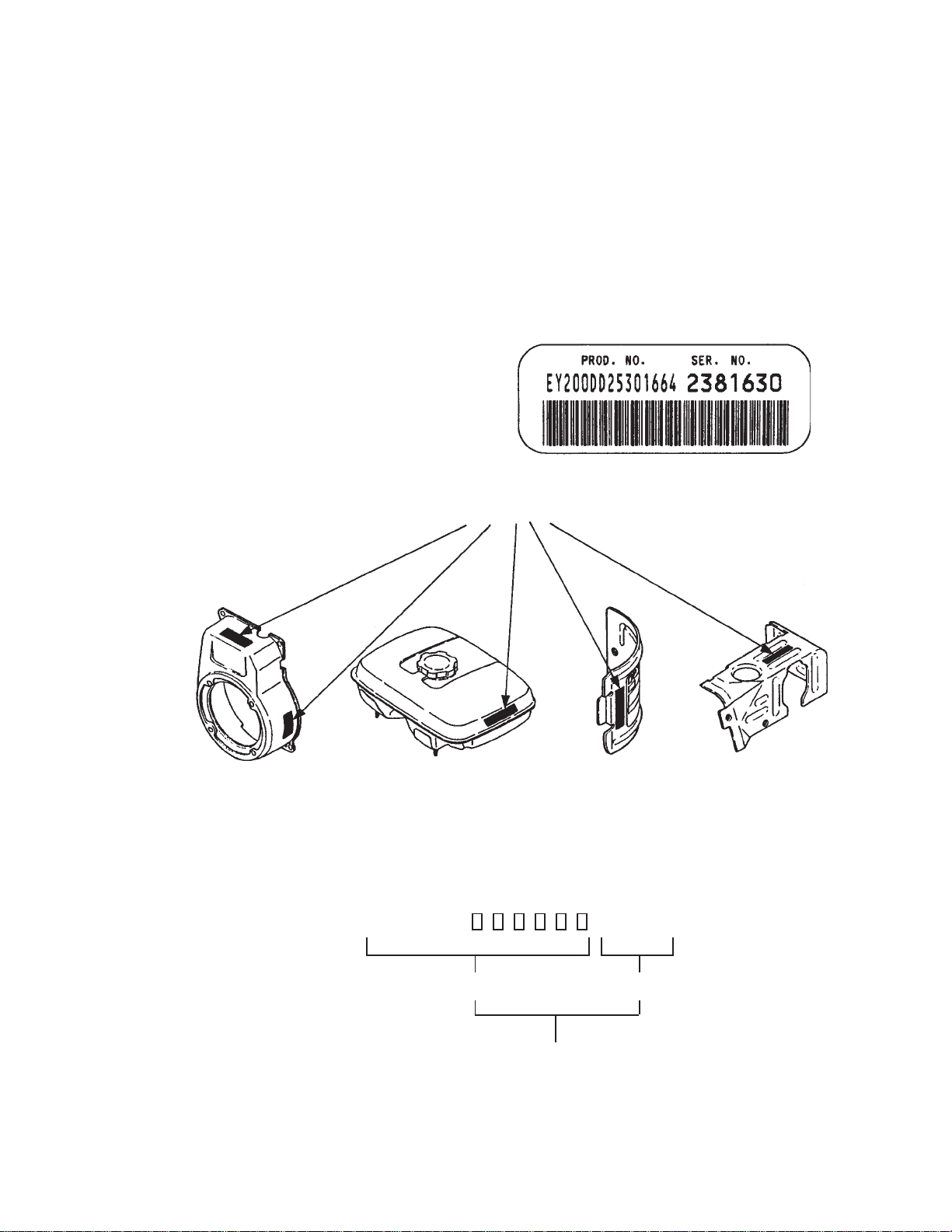
All Robin 4 cycle engines have a Product Number label similar to the label illustrated below.
PRODUCT NUMBER LABEL
PRODUCT NUMBER LABEL LOCATIONS
The Product Number Label has a 15 digit alphanumeric string that consists of the
SPECIFICATION (SPEC) number (11 digits) and the CODE number (4 digits). Please
note the illustration below:
E Y 2 8 0
SPEC NO. (11 digits) CODE NO. (4 digits)
PRODUCT NO. (15 digits)
EY28 - 3 - '00-02
X X X X
Page 4
MANUAL LAYOUT
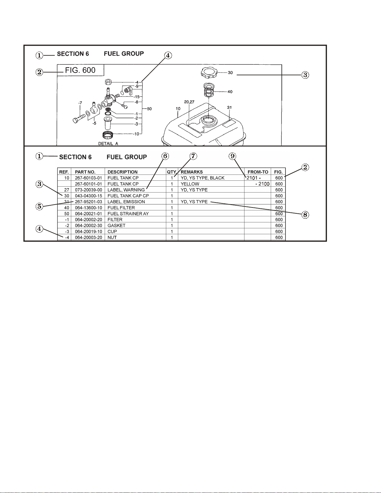
1. SECTION NAME Parts are broadly classified according to their functions.
Refer to the Group Index (table of contents) for respective section name.
2. FIG. No. The FIG. number indexes the reference and part numbers to the illustration. Figure numbers
that vary only in the tens place (i.e..: 700 and 710) are in a group of the same section
(i.e..:Electrical Device Group).
3. REF. No . The Reference number identifies the part illustration with the corresponding part number in the
part list.
4. SUBASSEMBLY SUBASSEMBLY parts of part assembly are listed below the assembly part. The subassembly
part reference number is indicated by the number led by "-" such as "-1", "-2".
5. PART NUMBER It is the number assigned for sales unit. Use the PART No. when making an order.
6. DESCRIPTION It is designation of the part.
7. QTY. Quantity of each part used for each product.
8. REMARKS This gives a distinctive feature and/or a supplementary comment for the type, the specification,
and the part concerned. It also shows part number(s) interchangeable for the part.
9. FROM-TO This section shows the CODE No. to indicate the history of progress in which improved parts
have been introduced in the product. The FROM-TO CODE No. helps to identify PART No.
being employed in the product concerned. See the examples below:
- The part is used in the product irrespective of CODE No.
2101- The part is used in the products with CODE No. of 2101 and after this number.
- 2100 The part is used in the products with CODE No. of 2100 and before this number.
EY28 - 4 - '00-02
Page 5

GROUP INDEX
Group Name Page
CRANKCASE GROUP ............................................................................... 6
CRANKSHAFT GROUP ............................................................................. 8
INTAKE and EXHAUST GROUP .............................................................. 10
GOVERNOR GROUP ............................................................................... 12
COOLING and ST ARTING GROUP ........................................................... 18
FUEL GROUP ........................................................................................... 24
FUEL GROUP - CARBURETOR ............................................................... 26
ELECTRIC DEVICE GROUP - RECOIL ST ART........................................ 28
ELECTRIC DEVICE GROUP - ELECTRIC STAR T................................... 30
ELECTRIC DEVICE GROUP - ST ARTING MOTOR.................................. 32
ELECTRIC DEVICE GROUP - OIL SENSOR............................................ 34
INDEX OF DESCRIPTION SYMBOLS
SYMBOL DESCRIPTION
AY .......................... ASSEMBLY
CP ..........................COMPLETE
EX .......................... EXPORT (from Japan)
FIG......................... FIGURE
FR. ......................... FRONT
".............................. INCH
INCL....................... INCLUDE
~L ........................... LITER
L= ........................... LENGTH (in. mm)
L.H. (LH) ................ LEFT-HAND SIDE
MECH .................... MECHANICAL
NO (NON) .............. NONE
OPT. ....................... OPTIONAL
O.S......................... OVER SIZE
SYMBOL DESCRIPTION
P= .......................... PITCH (in mm)
P.T.O. (PTO) .......... POWER TAKE OFF
REF. .......................REFERENCE
R.H. (RH) ............... RIGHT HAND SIDE
RR. ......................... REAR
STD........................STANDARD
SW ......................... SWITCH
T=........................... THICKNESS (in mm)
UN .......................... UNIT
U.S. ........................ UNDER SIZE
~V .......................... VOLTAGE
~W ......................... WATT
W/ .......................... WITH
W/O ........................ WITHOUT
EY28 - 5 - ''00-02
Page 6
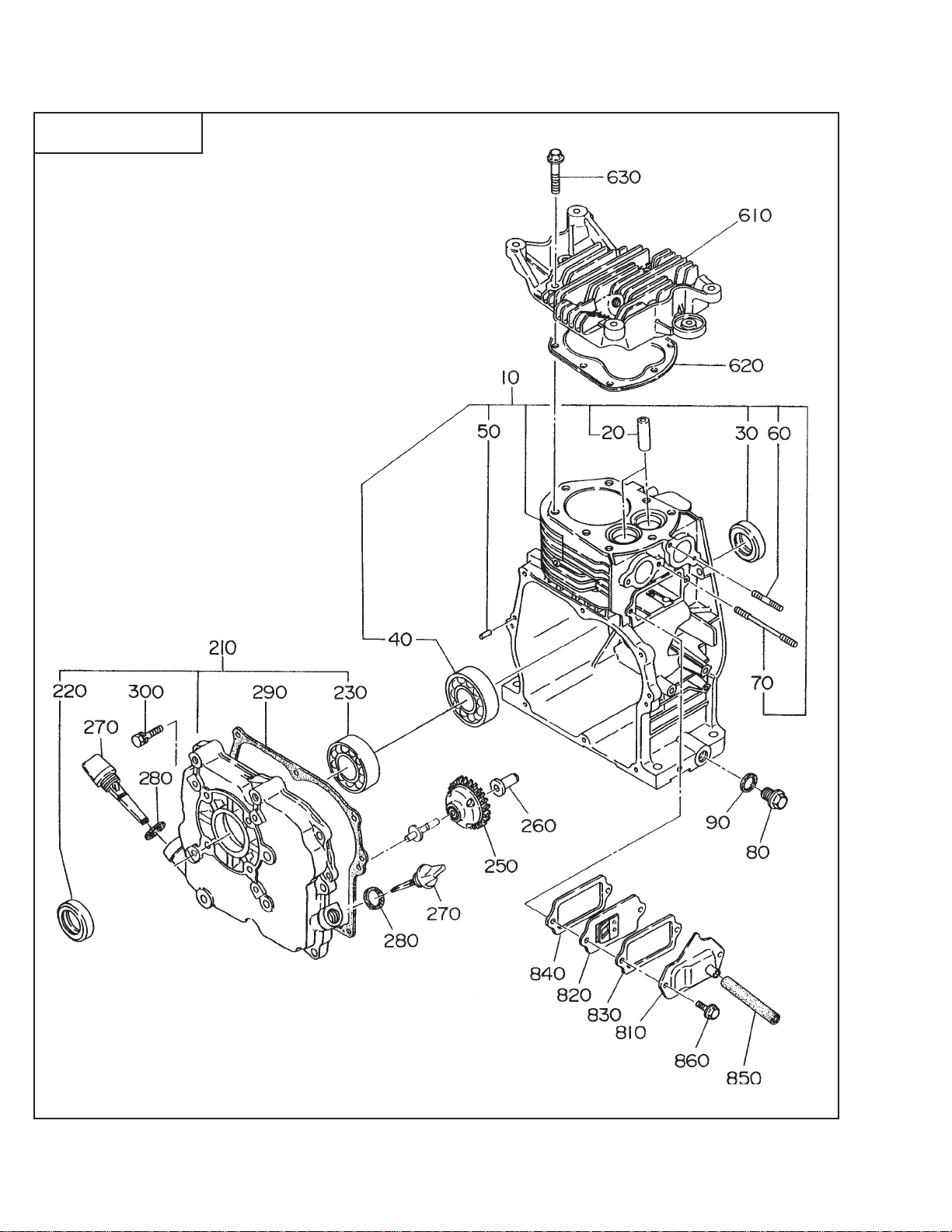
SECTION 1 CRANKCASE GROUP
FIG. 100
EY28 - 6 - '00-02
Page 7
SECTION 1 CRANKCASE GROUP
REF. P ART NO. DESCRIPTION QTY. REMARKS FROM-TO FIG.
10 234-10101-31 CRANKCASE, compl. 1 Recoil start type 100
234-10102-31 CRANKCASE, compl. 1 Electric start type 100
20 227-14202-03 VALVE GUIDE 2 Oversize 100
30 044-03000-30 OIL SEAL 1 100
40 060-03002-20 BALL BEARING 1 100
50 031-00600-20 DOWEL PIN 2 100
60 010-50802-90 STUD, muffler 2 100
70 010-50601-91 STUD, carburetor 2 100
80 040-11400-30 PLUG 2 100
90 021-11400-20 GASKET 2 100
210 234-12001-01 MAIN BEARING COVER, cp 1 SAE 100
234-11001-01 MAIN BEARING COVER, cp 1 Metric 100
220 044-03000-30 OIL SEAL 1 100
230 060-03002-20 BALL BEARING 1 100
250 234-45001-01 GOVERNOR GEAR, compl. 1 100
260 205-41901-03 GOVERNOR SLEEVE 1 100
270 227-63601-03 OIL GAUGE 2 100
227-63601-03 OIL GAUGE 1 Oil Sensor type 100
280 021-31600-20 GASKET 2 100
021-31600-20 GASKET 1 Oil Sensor type 100
290 234-16001-03 GASKET, bearing cover 1 100
300 001-14082-80 BO LT and WASHER AY 8 100
610 234-13001-23 CYLINDER HEAD, compl. 1 100
620 234-15001-01 GASKET, head 1 100
630 011-00800-10 FLANGE BOLT 8 100
810 234-14301-01 TAPPET COVER, compl. 1 100
820 234-14401-01 BREA THER PLA TE, compl. 1 100
830 234-16006-03 GASKET , tappet cover 1 100
840 234-16007-03 GASKET , breather plate 1 100
850 085-10800-00 RUBBER PIPE 1 Ø 8mm X Ø 11m m 100
860 011-00600-20 FLANGE BOLT 2 100
*960 234-99001-07 GASKET SET 1 100
* Gasket set includes the following:
Fig. 100 items 280, 290, 620, 830 and 840
Fig. 300 items 340, 550 and 560
Fig. 310 item 510-2*
EY28 - 7 - '00-02
Page 8
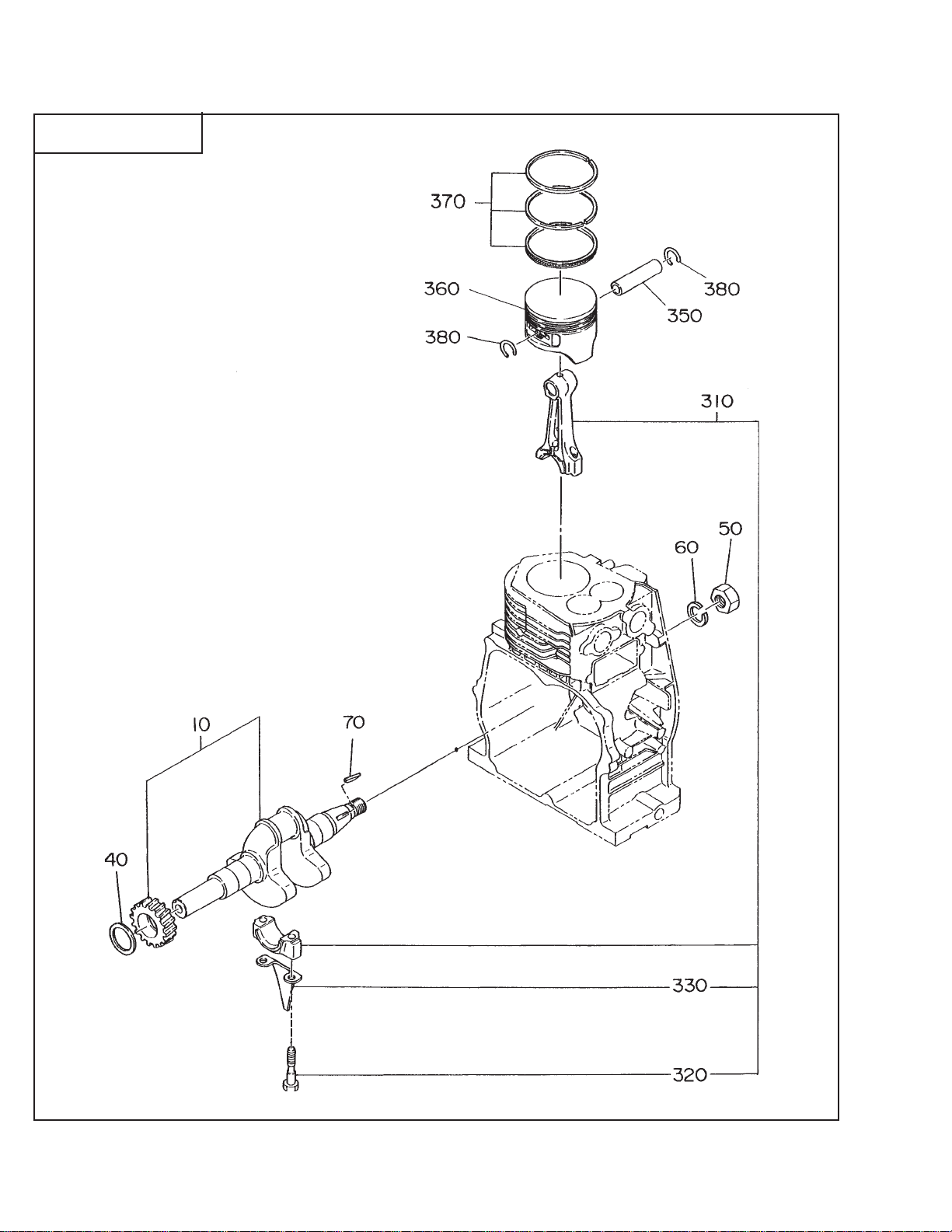
SECTION 2 CRANKSHAFT GROUP
FIG. 200
EY28 - 8 - '00-02
Page 9

SECTION 2 CRANKSHAFT GROUP
REF. P ART NO. DESCRIPTION QTY. REMARKS FROM-TO FIG.
10 234-20901-1 1 CRANKSHAFT, compl. 1 SAE, 1 in keyed 200
234-21001-1 1 CRANKSHAFT, compl. 1 SAE, PUMP type 200
234-21201-1 1 CRANKSHAFT , compl. 1 SAE, T APER type 200
234-20201-1 1 CRANKSHAFT , compl. 1 25mm keyed 200
234-20301-1 1 CRANKSHAFT , compl. 1 Metric Pump 200
234-20701-1 1 CRANKSHAFT , compl. 1 Metric Taper 200
40 023-03001-70 SPACER, T=0.6 1 select one piece only 20 0
023-03001-80 SPACER, T=0.8 1 select one piece only 20 0
023-03001-90 SPACER, T=1.0 1 select one piece only 20 0
50 002-18180-00 NU T 1 200
60 003-20180-00 SPRING WASHER 1 200
70 032-30300-10 WOODRUFF KEY 1 200
310 234-22501-10 CONNECTING ROD AY 1 200
320 227-23001-13 CONNECTING ROD BOLT 2 200
330 234-23101-03 OIL SCRAPER 1 200
350 234-23301-03 PISTON PIN 1 200
360 234-23401-03 PISTON 1 STD 200
234-23402-03 PISTON 1 oversize 0.25mm 200
234-23403-03 PISTON 1 oversize 0.50mm 200
370 254-23501-07 PISTON RING SET 1 S TD 200
254-23502-07 PISTON RING SET 1 oversize 0.25mm 200
254-23503-07 PISTON RING SET 1 oversize 0.50mm 200
380 056-51600-10 CLIP 2 200
EY28 - 9 - '00-02
Page 10
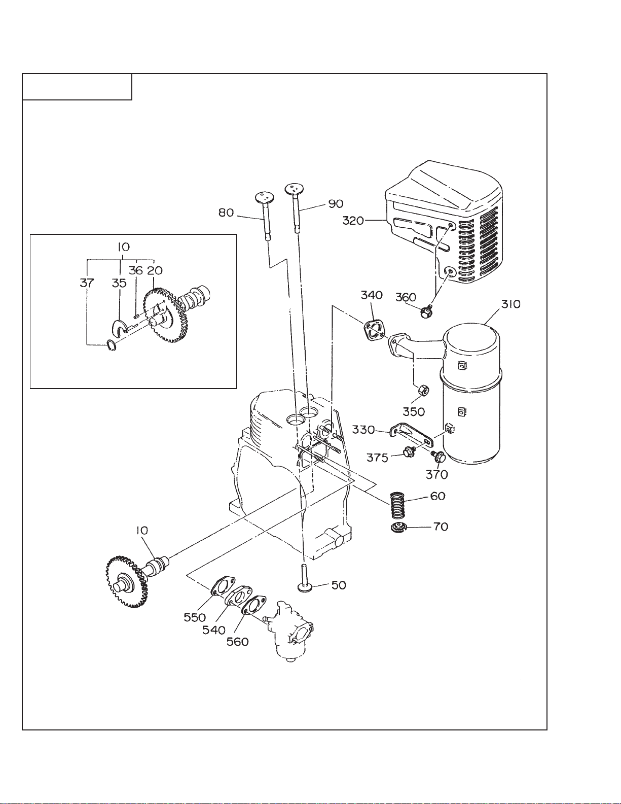
SECTION 3 INTAKE and EXHAUST GROUP
FIG. 300
COMPRESSION RELEASE TYPE
EY28 - 10 - '00-02
Page 11

SECTION 3 INTAKE and EXHAUST GROUP
REF. P ART NO. DESCRIPTION QTY. REMARKS FROM-TO FIG.
10 234-32301-01 CAMSHAFT, compl. 1 Compression release type 30 0
234-31701-03 CAMSHAFT, compl. 1 300
20 234-32301-03 CAMSHAFT 1 Comperssion release type 300
35 232-36401-13 RELEASE LEVER 1 Compression release type From 4474 3 00
232-36401-03 RELEASE LEVER 1 Compression release type T o 4473 300
36 005-19041-00 SPRING PIN 1 Compression release type 300
37 003-15280-00 SNAP RING, OUTER 1 Compression release type 300
50 234-33301-03 TAPPET 2 300
60 227-33601-03 VLAVE SPRING 2 300
70 234-33401-03 SPRING RETAINER 2 300
80 234-33701-03 INTAKE VALVE 1 300
90 234-33501-03 EXHAUST VAL VE 1 300
310 234-30101-01 MUFFLER, compl. 1 300
320 234-34201-01 MUFFLER COVER, compl. 1 300
330 234-35301-01 MUFFLER BRACKET , compl. 1 300
340 234-35201-01 GASKET , exhaust 1 300
350 002-19080-00 NUT 2 300
360 011-00600-10 FLANGE BOLT 4 300
370 011-00600-10 FLANGE BOLT 1 300
375 011-00600-20 FLANGE BOLT 1 300
540 234-32901-03 INSULAT O R 1 300
550 234-35901-03 GASKET, insulator 1 300
560 234-35902-03 GASKET 2, insulator 1 300
EY28 - 11 - '00-02
Page 12
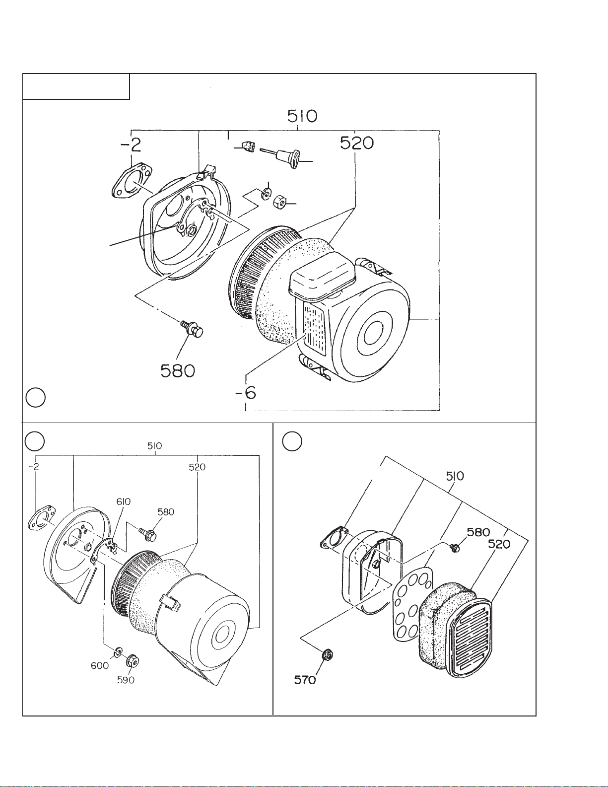
SECTION 3 INTAKE and EXHAUST GROUP
FIG. 310
-3
650
600
590
610
A
B
C
-2
EY28 - 12 - '00-02
Page 13

SECTION 3 INTAKE and EXHAUST GROUP
REF. PART NO. DESCRIPTION QTY. REMARKS FROM-TO FIG.
510 234-32628-00 AIR CLEANER, AY 1 Standard Premium 310A
234-32624-00 AIR CLEANER, AY 1 Standard 310B
234-32601-00 AIR CLEANER, AY 1 Foam 310C
-2 234-36003-03 PACKING 1 310
-3 207-32690-08 GROMMET 1 310A
520 234-36004-07 ELEMENT SET 1 Standard Premium 310A
234-36004-07 ELEMENT SET 1 Standard 310B
234-36002-03 ELEMENT SET 1 Foam 310C
570 002-38060-00 FLANGE NUT 2 310C
580 001-10061-20 BOLT and WASHER A Y 1 310
590 226-39212-00 FLANGE NUT 2 From 3013 310
002-17060-00 NU T 2 T o 3012 310
600 003-20060-00 SPRING 2 To 3012 310
610 234-36501-01 LOCK WASHER, compl. 1 To 3012 310
650 206-43901-01 KNOB 1 310A
EY28 - 13 - '00-02
Page 14

SECTION 4 GOVERNOR GROUP
FIG. 400
MANUAL CONTROL ONLY
MANUAL WITH UPPER REMOTE CABLE CONTROL
EY28 - 14 - '00-02
Page 15

SECTION 4 GOVERNOR GROUP
REF. P ART NO. DESCRIPTION QTY. REMARKS FROM-TO FIG.
10 234-42308-01 GOVERNOR LEVER, compl. 1 400
20 234-42201-03 GOVERNOR SHAFT 1 400
30 234-42701-01 GOVERNOR ROD 1 400
40 234-42801-13 ROD SPRING 1 400
50 003-13060-00 CLIP 2 400
60 001-14062-50 BOLT and WASHER AY 1 40 0
70 018-60600-20 NU T 1 400
80 234-42501-13 GOVERNOR SPRING 1 400
310 234-43301-00 SPEED CONTROL AY 1 Manual throttle control only 400
234-43302-00 SPEED CONTROL A Y 1 Upper cable control only 400
320 234-43301-01 SPEED CONTROL, compl. 1 Manual throttle control only 4 00
234-43302-01 SPEED CONTROL, compl. 1 Upper cable control only 400
330 227-43601-03 KNOB 1 400
340 227-43501-13 STOP PLA TE 1 400
350 227-45002-03 SPRING WASHER 1 400
360 004-31064-00 SCREW 1 400
370 002-27060-00 NUT 1 400
380 011-00600-30 FLANGE BOLT 1 Manual throttle control only 400
011-00600-50 FLANGE BOLT 1 Upper cable control only 400
390 234-44202-13 WIRE BRACKET, compl. 1 Upper cable control only 400
440 004-31040-80 SCREW 1 Upper cable control only 400
450 002-27060-00 NUT 1 Upper cable control only 400
EY28 - 15 - '00-02
Page 16

SECTION 4 GOVERNOR GROUP
FIG. 410
LOWER REMOTE CABLE CONTROL
EY28 - 16 - '00-02
Page 17

SECTION 4 GOVERNOR GROUP
REF. PART NO. DESCRIPTION QTY. REMARKS FROM-TO FIG.
10 234-42308-01 GOVERNOR LEVER, compl. 1 410
20 234-42201-03 GOVERNOR SHAFT 1 410
30 234-42701-01 GOVERNOR ROD 1 410
40 234-42801-13 ROD SPRING 1 410
50 003-13060-00 CLIP 2 410
60 001-14062-50 BOLT and WASHER AY 1 410
70 018-60600-20 NUT 1 410
80 234-42503-23 GOVERNOR SPRING 1 Lower cable control 41 0
200 234-43301-11 SPEED CONTROL 2, compl. 1 Lower cable control From 3440 4 1 0
234-43304-01 SPEED CONTROL 2, compl. 1 Lower cable control To 3439 410
210 001-60400-10 BOL T 1 Lower cable control 4 10
230 004-31053-00 SCREW 1 Lower cable control 4 10
240 002-17050-00 NU T 1 Lower cable control 4 10
280 261-43101-01 LINK PIVOT 1 Lower cable control 4 10
390 234-44201-13 WIRE BRACKET , compl. 1 Lower cable control From 3440 4 10
234-44201-01 WIRE BRACKET, compl. 1 Lower cable control T o 3439 410
420 011-00600-20 FLANGE BOLT 1 Lower cable control 41 0
EY28 - 17 - '00-02
Page 18

SECTION 5 COOLING and STARTING GROUP
FIG. 500
EY28 - 18 - '00-02
Page 19

SECTION 5 COOLING and STARTING GROUP
REF. P ART NO. DESCRIPTION QTY. REMARKS FROM-TO FIG.
10 234-51506-06 BLOWER HOUSING, compl. 1 Recoil type, Black 500
234-51 101-07 BLOWER HOUSING, compl. 1 Recoil type, Primer 500
234-51202-06 BLOWER HOUSING, compl. 1 Recoil type, Orange 500
234-51201-06 BLOWER HOUSING, compl. 1 Recoil type, Y ellow 500
234-51405-06 BLOWER HOUSING, compl. 1 Electric start type, Black 500
20 234-91636-03 LABEL, trademark 1 Robin / Subaru 500
40 011-00600-20 FLANGE BOLT 5 500
60 234-52601-03 CYLINDER BAFFLE 1 500
80 011-00600-20 FLANGE BOLT 1 500
90 234-52701-03 HEAD COVER 1 500
EY28 - 19 - '00-02
Page 20

SECTION 5 COOLING and STARTING GROUP - NEW STYLE
FIG. 510
Standard Rotation
Reverse Rotation
-11
230
-13 -12 -6 -5 -7 -2 -3
220
-1
-4
210
EY28 - 20 - '00-02
Page 21

SECTION 5 COOLING and STARTING GROUP - NEW STYLE
REF. PART NO. DESCRIPTION QTY. REMARKS FROM-TO FIG.
210 234-50221-10 RECOIL STARTER A Y 1 STD. Rotation From 1948 5 10
234-50121-00 RECOIL STARTER AY 1 Reverse Rotation From 2465 510
-1 215-50515-08 SPIRAL SPRING 1 STD Rotation From 1309 51 0
215-50515-08 SPIRAL SPRING 1 Reverse Rotation From 2466 510
-2 234-50120-18 REEL, compl. 1 STD Rotation From 1948 510
234-50120-18 REEL, compl. 1 Reverse Rotation From 2466 51 0
-3 234-50183-08 STARTER ROPE 1 510
-4 226-50100-08 STARTER KNOB 1 510
-5 161-50125-08 RAT C HE T 2 510
-6 227-50131-08 FRICTION SPRING 1 510
-7 227-50135-08 RETURN SPRING 2 510
-11 234-50146-18 STARTER PULLEY 1 510
-12 161-50150-08 RATCHET GUIDE 1 STD Rotation From 1309 51 0
252-50150-08 RATCHET GUIDE 1 Reverse Rotation From 2466 51 0
-13 227-50152-08 SET SCREW 1 510
-14 224-50150-08 KNOB CAP 1 STD. Rotation 510
220 011-00600-10 FLANGE BOLT 4 510
230 011-00600-30 FLANGE BOLT 1 510
EY28 - 21 - '00-02
Page 22

SECTION 5 RECOIL STARTER - OLD STYLE
FIG. 520
Standard Rotation
Reverse Rotation
EY28 - 22 - '00-02
Page 23

SECTION 5 RECOIL STARTER - OLD STYLE
REF. P ART NO. DESCRIPTION QTY. REMARKS FROM-TO FIG.
210 234-50221-10 RECOIL STARTER A Y 1 STD. Rotation T o 1308 520
234-50111-00 RECOIL STARTER A Y 1 Reverse Rotation To 2465 520
-1 106-50116-08 SPIRAL SPRING 1 STD Rotation T o 1308 520
106-50116-08 SPIRAL SPRING 1 Reverse Rotation T o 2465 520
-2 207-50122-18 REEL, compl. 1 520
-3 106-50113-08 STARTER ROPE 1 520
-4 206-50101-08 STARTER KNOB 1 520
-5 106-50128-18 RATCHET 2 520
-6 106-50132-08 FRICTION SPRING 1 520
-7 106-50136-08 RETURN SPRING 2 STD. Rotation T o 1308 520
106-50137-08 RETURN SPRING 2 Reverse Rotation T o 2465 520
-8 106-50144-08 FRICTION SPRING 1 520
-9 106-50185-08 THRUST WASHER 1 520
-10 106-50186-08 CLIP 1 520
-11 234-50145-08 STARTER PULLEY 1 520
220 01 1-00600-10 FLANGE BOLT 4 520
230 01 1-00600-30 FLANGE BOLT 1 520
EY28 - 23 - '00-02
Page 24

SECTION 6 FUEL GROUP
FIG. 600
EY28 - 24 - '00-02
Page 25

SECTION 6 FUEL GROUP
REF. P ART NO. DESCRIPTION QTY. REMARKS FROM-TO FIG.
10 234-61 104-01 FUEL TANK 1 Black 600
234-61 150-01 FUEL TANK 1 Orange 600
234-60101-01 FUEL TANK 1 Y ellow 600
27 073-20039-00 LABEL, caution 1 600
30 043-04300-15 FUEL TANK CAP, compl. 1 600
40 064-13600-10 FUEL FILTE R 1 600
50 064-20064-00 FUEL STRAINER 1 600
-1 064-20064-20 FIL T ER 1 600
-2 064-20064-10 PACKING 1 6 0 0
-3 064-20042-10 CUP 1 600
-4 064-20064-30 NUT 1 600
-5 064-20064-40 PACKING 1 6 0 0
60 002-38080-00 FLANGE NUT 4 600
70 234-62601-01 FUEL PIPE, compl. 1 600
80 085-10600-00 RUBBER PIPE 1 Ø 6mm X Ø 12mm 600
90 056-11 100-20 HOSE CLAMP 2 600
EY28 - 25 - '00-02
Page 26

SECTION 6 FUEL GROUP - CARBURETOR
FIG. 610
210
EY28 - 26 - '00-02
Page 27

SECTION 6 FUEL GROUP - CARBURETOR
REF. P ART NO. DESCRIPTION QTY . REMARKS FROM-TO FIG.
210 234-62551-00 CARBURETOR AY 1 Premium 61 0
234-62502-00 CARBURETOR AY 1 Value Line 61 0
234-62505-00 CARBURETOR AY 1 Homelite Gen./ EY280YD2510 610
-1 234-62541-08 THROTTLE VAL VE 1 Premium 610
213-62537-08 THROTTLE VAL VE 1 Value Line 610
213-62537-08 THROTTLE VAL VE 1 Homelite Gen./ EY280YD2510 61 0
-2 209-62351-08 SCREW 2 610
-3 234-62527-08 CHOKE VALVE 1 Premium 610
234-62525-08 CHOKE VALVE 1 Value Line 610
234-62525-08 CHOKE VALVE 1 Homelite 610
-4 237-62451-08 SCREW 2 610
-5 234-62421-08 PILOT JET 1 610
-6 234-62435-08 ADJUSTER 1 610
-7 206-62446-08 SPRING 1 610
-8 234-62521-08 CHOKE LEVER AY 1 Premium, used w/ remote pull 610
234-62520-08 CHOKE LEVER AY 1 Value Line 610
234-62520-08 CHOKE LEVER AY 1 Homelite Gen./ EY280YD2510 610
-9 239-62560-08 RING, choke 1 610
-11 234-62536-08 THROTTLE SHAFT AY 1 610
-12 129-62351-08 BOLT 1 610
-13 226-62550-08 RING 1 610
-14 224-62312-18 NEEDLE VALVE AY 1 610
-15 214-62515-08 PIN 1 610
-16 224-62552-08 FLOAT CHAMBER BODY 1 610
-17 207-62345-08 INSERT WASHER 1 610
-18 206-62540-08 CHAMBER PACKING 1 61 0
-19 234-62506-08 FLOAT A Y 1 610
-20 234-62443-08 NOZZLE 1 Premium 6 10
234-62440-08 NOZZLE 1 Value Line 610
234-62440-08 NOZZLE 1 Homelite Gen./ EY280YD2510 610
-22 234-62404-08 MAIN JET 1 610
-24 224-62569-18 CLIP 1 Premium 610
224-62569-18 CLIP 1 V alue Line 610
224-62569-18 CLIP 1 Homelite Gen./ EY280YD2510 610
-32 106-62392-08 SEAL 1 610
-40 224-62452-08 SCREW 1 6 10
-41 230-62446-08 SPRING 1 610
-60 156-62351-08 PACKING 1 610
-61 247-62550-08 CAP, choke 1 610
-62 236-62680-08 SEAL 1 610
-90 234-62425-08 PIPE AY 1 610
-121 246-62551-08 CAP 1 610
EY28 - 27 - '00-02
Page 28

SECTION 7A ELECTRIC DEVICE GROUP - RECOIL START
FIG. 700
EY28 - 28 - '00-02
Page 29

SECTION 7A ELECTRIC DEVICE GROUP - RECOIL START
REF. P ART NO. DESCRIPTION QTY. REMARKS FROM-TO FIG.
10 234-70201-1 1 FLYWHEEL, compl. 1 STD. Rotation 700
234-70101-1 1 FLYWHEEL, compl. 1 Reverse Rotation 700
1 1 234-70124-21 IGNITION COIL, compl. 1 700
30 001-17062-50 BOLT and WASHER AY 2 700
50 214-73201-01 WIRE 1, compl. 1 700
60 066-00003-71 SWITCH AY 1 700
066-20000-11 STOP BUTTON 1 Obsolete, use 066-00003-71 700
70 015-00400-90 TAPPING SCREW 2 700
80 226-75501-03 GROMMET 1 700
90 206-75501-01 CLAMP 1 700
100 065-01404-20 SP ARK PLUG 1 NGK BP6HS 700
110 065-50000-51 SPARK PLUG CAP 1 700
EY28 - 29 - '00-02
Page 30

SECTION 7B ELECTRIC DEVICE GROUP - ELECTRIC START
FIG. 710
EY28 - 30 - '00-02
Page 31

SECTION 7B ELECTRIC DEVICE GROUP - ELECTRIC START
REF. P ART NO. DESCRIPTION QTY. REMARKS FROM-TO FIG.
10 234-70203-1 1 FLYWHEEL, compl. 1 Electric Start 710
1 1 234-70124-21 IGNITION COIL, compl. 1 710
12 234-70166-01 CHARGE COIL, compl. 1 710
20 263-71002-03 RING GE AR 1 710
30 001-17062-50 BOLT and WASHER AY 4 710
40 207-75001-01 CLAMP, compl. 1 710
80 226-75501-03 GROMMET 1 710
90 206-75501-01 CLAMP 1 710
100 065-01404-20 SP ARK PLUG 1 NGK BP6HS 710
110 065-50000-51 SPARK PLUG CAP 1 710
120 234-70502-00 STARTING MOTOR 1 710
130 214-79007-01 BOL T , compl. 2 710
140 002-17080-00 NUT 1 710
150 003-10080-00 WASHER 2 710
160 003-20080-00 SPRING WASHER 3 710
170 001-10061-20 BOL T and WASHER AY 1 710
180 001-10081-60 BOL T and WASHER AY 2 710
190 073-20044-80 LABEL, battery 1 710
200 234-75101-11 CONTROL BOX, compl. 1 710
210 073-20044-60 LABEL, starter switch 1 710
220 066-00003-30 SWITCH 1 From 2405 710
066-00001-1 1 SWITCH 1 T o 2404 710
-1 066-00099-80 KEY, switch 1 From 2405 710
066-00099-90 KEY 1 T o 2404 71 0
230 209-71401-01 DIODE RECTIFIER, compl. 1 710
240 011-00600-10 FLANGE BOLT 1 710
250 224-73102-01 WIRE 3, compl. 1 710
260 234-73122-01 WIRE 22, compl. 1 710
270 234-73123-01 WIRE 23, compl. 1 710
EY28 - 31 - '00-02
Page 32

SECTION 7C ELECTRIC DEVICE GROUP - STARTING MOTOR
FIG. 720
120
EY28 - 32 - '00-02
Page 33

SECTION 7C ELECTRIC DEVICE GROUP - STARTING MOTOR
REF. P ART NO. DESCRIPTION QTY. REMARKS FROM-TO FIG.
120 234-70502-00 STARTING MOTOR 1 Includes items -1 thru -22 720
-1 209-70550-08 yoke, COMPL. 1 720
-2 209-70551-08 BRUSH 4 720
-3 209-70545-08 SPRING, brush 4 720
-4 209-70530-08 BRUSH HOLDER 1 720
-5 209-70552-08 INSULATO R 1 720
-6 234-70554-08 ARMATURE A Y 1 720
-7 234-70521-08 CLUTCH, compl. 1 720
-8 234-70555-08 PINION STOPPER 1 720
-9 234-70500-08 HOUSING AY 1 720
-10 209-70511-08 BUSHING 1 720
-11 234-70505-18 FRAME, compl. 1 720
-12 209-70510-08 BUSHING 1 720
-14 209-70525-08 LEVER 1 720
-15 209-70515-08 MAGNETIC SWITCH, compl. 1 720
-16 209-70557-18 SNAP RING 1 720
-17 209-70558-08 BOLT , through 2 720
-18 949-29970-02 NUT 2 720
-19 209-70560-08 NUT 1 720
-21 107-70562-08 SPRING WASHER 1 720
-22 211-70584-08 NUT 1 720
EY28 - 33 - '00-02
Page 34

SECTION 7D ELECTRIC DEVICE GROUP - OIL SENSOR
FIG. 730
OLD STYLE
OPPOSITE CARBURETOR SIDE
NEW STYLE
EY28 - 34 - '00-02
Page 35

SECTION 7D ELECTRIC DEVICE GROUP - OIL SENSOR
REF. P ART NO. DESCRIPTION QTY. REMARKS FROM-TO FIG.
700 KS3-11017-01 OIL LEVEL SENSOR, compl. 1 New style, opp. carb side From 2617 7 30
234-76001-1 1 OIL LEVEL SENSOR, compl. 1 Old style, opp. carb. side To 2616 730
710 234-76201-03 JOINT 1 Old style, opp. carb. side To 2616 730
715 227-77002-00 LED LAMP AY 1 730
720 227-78001-03 BUSHING, cord 1 Old style To 2616 73 0
730 234-76501-01 BRACKET, compl. 1 Old style To 2616 730
740 004-36061-00 SCREW and WASHER AY 2 Old style To 2616 730
750 001-10081-60 BOLT and WASHER AY 2 730
760 214-73122-01 WIRE 22, compl. 1 730
770 207-75001-01 CLAMP, compl. 1 730
810 056-60002-50 CLAMP, compl. 1 730
820 214-79003-01 CLAMP, compl. 1 New style From 2617 730
EY28 - 35 - '00-02
Page 36

SECTION 7E ELECTRIC DEVICE GROUP - OIL SENSOR
FIG. 740
750
820
OLD STYLE
CARBURETOR SIDE
760
770
770
OPTIONAL LED
LAMP
700
830
740
700
750
770
770
760
NEW STYLE
730
710
830
EY28 - 36 - '00-02
Page 37

SECTION 7E ELECTRIC DEVICE GROUP - OIL SENSOR
REF. P ART NO. DESCRIPTION QTY. REMARKS FROM-TO FIG.
700 KS3-11016-01 OIL LEVEL SENSOR, compl. 1 New style, carb. side From 2617 740
234-76104-01 OIL LEVEL SENSOR, compl. 1 Old style, carb. side To 2616 740
710 234-76201-03 JOINT 1 Old style, carb. side To 2616 740
715 227-77002-00 LED LAMP AY 1 740
730 234-76501-01 BRACKET, compl. 1 Old style To 2616 740
740 004-36061-00 SCREW and WASHER AY 2 Old style To 2616 740
750 001-10081-60 BOLT and WASHER AY 2 740
760 214-73122-01 WIRE 22, compl. 1 740
770 207-75001-01 CLAMP, compl. 2 740
810 056-60002-50 CLAMP, ompl. 1 740
820 214-79003-01 CLAMP, compl. 1 New style From 2617 740
830 021-31600-20 GASKET 1 740
EY28 - 37 - '00-02
Page 38

SECTION 8 6:1 GEAR REDUCTION
FIG. 800
20
10
EY28 - 38 - '00-02
Page 39

SECTION 8 6:1 GEAR REDUCTION
REF. P ART NO. DESCRIPTION QTY. REMARKS FROM-TO FIG.
1 234-20801-11 CRANKSHAFT 1 800
2 234-80101-01 REDUCTION CASE 1 800
3 234-85101-03 GASKET A 1 800
4 010-10800-30 BOL T 2 800
5 010-10800-80 BOL T 2 800
6 003-20080-00 SPRING WASHER 2 800
7 003-10080-00 WASHER 2 80 0
8 003-38080-00 LOCK WASHER 2 800
9 207-81101-13 DRIVING SHAFT 1 800
10 060-01500-20 BALL BEARING 2 800
1 1 207-80701-01 REDUCTION COVER, compl. 1 800
12 060-03002-20 BALL BEARING 1 800
13 206-95001-03 LABEL, oil filler 1 800
14 206-95002-03 LABEL, level mark 1 800
15 044-03000-30 OIL SEAL 1 800
16 206-85102-03 GASKET B 1 800
17 206-85001-03 PLUG A 1 800
18 206-85002-03 PLUG B 1 800
19 001-14082-50 BOLT and WASHE R 4 800
20 234-12003-01 MAIN BEARING COVER 1 800
25 044-02501-70 OIL SEAL 1 800
EY28 - 39 - '00-02
Page 40

PRINTED IN THE USA
 Loading...