

Page 1

SERVICE
MANUAL
Models
EY15-3, EY20-3
ENGINES
PUB-ES1609
Rev. 12/01
Page 2

940 Lively Blvd. • Wood Dale, IL 60191 • Phone: 630-350-8200 • Fax: 630-350-8212
e-mail: sales@robinamerica.com • www.robinamerica.com
© Copyright 2001 Robin America, Inc.
Page 3

CONTENTS
Section Title Page
1. SPECIFICATIONS....................................................................................................... 1
2. PERFORMANCE ........................................................................................................2
2-1 MAXIMUM OUTPUT........................................................................................................ 2
2-2 CONTINUOUS RATED OUTPUT .................................................................................... 2
2-3 MAXIMUM TORQUE ....................................................................................................... 2
2-4 PERFORMANCE CURVES ............................................................................................. 3
3. FEATURES (compared with former models)........................................................... 5
4. GENERAL DESCRIPTION OF ENGINE COMPONENTS .......................................... 6
4-1 CYLINDER AND CRANKCASE....................................................................................... 6
4-2 MAIN BEARING COVER ................................................................................................. 6
4-3 CRANKSHAFT.................................................................................................................6
4-4 CONNECTING ROD AND PISTON ................................................................................. 7
4-5 CAMSHAFT ..................................................................................................................... 7
4-6 VALVE ARRANGEMENT ................................................................................................. 7
4-7 CYLINDER HEAD............................................................................................................ 8
4-8 GOVERNOR SYSTEM .................................................................................................... 8
4-9 COOLING SYSTEM......................................................................................................... 8
4-10 LUBRICATION SYSTEM ............................................................................................... 8
4-11 IGNITION SYSTEM........................................................................................................ 9
4-12 CARBURETOR.............................................................................................................. 9
4-13 AIR CLEANER ...............................................................................................................9
4-14 SECTIONAL VIEW OF ENGINE.................................................................................. 10
5. DISASSEMBLY AND REASSEMBLY ....................................................................... 12
5-1 PREPARATIONS AND SUGGESTIONS........................................................................ 12
5-2 SPECIAL TOOLS ........................................................................................................... 12
5-3 DISASSEMBLY PROCEDURES.................................................................................... 13
5-4 REASSEMBLY PROCEDURES..................................................................................... 20
5-5 BREAK-IN OPERATION OF REASSEMBLED ENGINE ............................................... 27
6. GOVERNER ADJUSTMENT.....................................................................................28
7. CARBURETOR ......................................................................................................... 30
7-1 OPERATION AND CONSTRUCTION............................................................................ 30
7-2 DISASSEMBLY AND REASSEMBLY ............................................................................ 31
8. MAGNETO ................................................................................................................ 33
8-1 FEATURES .................................................................................................................... 33
8-2 BASIC PRINCIPLE OF U.T.C.I. ..................................................................................... 33
8-3 MAGNETO TROUBLESHOOTING................................................................................ 34
Page 4

1. SPECIFICATIONS
LEDOMD3-51YED3-02YE
epyT
ekortSxeroB).ni18.1x84.2(mm64x36).ni50.2x46.2(mm25x76
tnemecalpsiDnotsiPmc341
3
oitaRnoisserpmoC 3.6
suounitnoC
tuptuO
.xaM.m.p.r0004/)PH5.3(Wk6.2.m.p.r0004/)PH0.5(Wk7.3
euqroT.xaM
N7.6 ・ fgk86.0(m ・ .m.p.r0082/)mN3.9 ・ fgk59.0(m ・ .m.p.r0082/)m
noitatoRfonoitceriD edistfahs.O.T.PmorfdeweivsaesiwkcolcretnuoC
metsysgnilooC gnilooCriAdecroF
tnemegnarrAevlaV evlaVediS
noitacirbuL epyThsalpS
tnacirbuL rehgihroESssalC;03-W01ro03#,02#EASliOelibomotuA
tnacirbuLfoyticapaC ).lag.S.U651.0(sretil6.0
roterubraC epyTtaolF,tfarDlatnoziroH
).ni.uc37.8(mc381
.m.p.r0003/)PH2.2(Wk6.1
.m.p.r0063/)PH7.2(Wk0.2
,rednilyC-elgniS,elcyC-4,delooC-riA
enignEenilosaG,evlaVediS
3
).ni.uc71.11(
.m.p.r0003/)PH0.3(Wk2.2
.m.p.r0063/)PH5.3(Wk6.2
leuF enilosaGdedaelnUelibomotuA
oitaRnoitpmusnoCleuFWk/g083
metsySdeeFleuF epyTytivarG
yticapaCknaTleuF).lag.S.U47.0(sretil8.2).lag.S.U00.1(sretil8.3
metsySnoitingI )etatSdiloS(otengaMleehwylF
gulPkrapS SH6BKGN
metsySgnitratS retratSlioceR
metsySronrevoG epyTthgiewylFlagufirtneC
thgieWyrD).bl1.92(gk2.31).bl1.33(gk0.51
)HxWxL(snoisnemiD
Specifications are subject to change without notice.
・ PH/g082(h ・ tuptuOdetaRsuounitnoCta)h
mm863xmm403xmm492
mm293xmm813xmm303
).ni94.41x.ni79.11x.ni75.11(
).ni34.51x.ni25.21x.ni39.11(
- 1 -
Page 5

2. PERFORMANCE
2-1 MAXIMUM OUTPUT
The maximum output is the output of an engine with its throttle valve fully opened and considering that all
the moving parts are properly broken in .
A new engine may not produce full maximum output while its moving parts are still not broken-in.
NOTE :
Power curves shown in the following charts are made in conformity with SAE internal combustion engine
standard test code J1349.
2-2 CONTINUOUS RATED OUTPUT
The continuous rated output is the output of an engine at optimum governed speed which is most favorable from the view point of engine's life and fuel consumption.
When the engine is installed on a certain equipment, it is recommended that the continuous output
required from the equipment should be kept below this continuous rated output.
2-3 MAXIMUM TORQUE
The maximum torque is the torque at the output shaft when the engine is producing maximum output at
a specified r.p.m..
- 2 -
Page 6
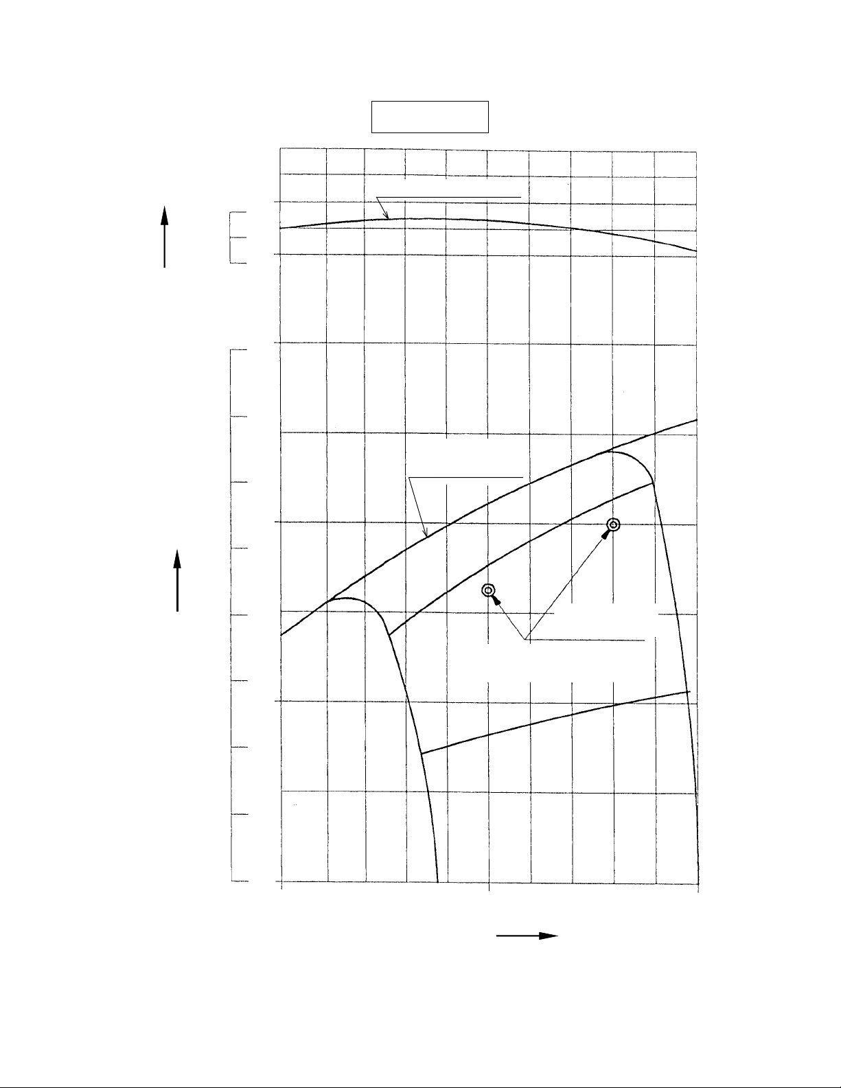
2-4 PERFORMANCE CURVES
(kgf.m) N.m
7
0.7
EY15-3D
MAXIMUM TORQUE
TORQUE
OUTPUT
0.6
(HP) kW
4
3
2
6
3
MAXIMUM
HORSEPOWER
2
CONTINUOUS
RATED HP
1
1
00
2 0 0 0
RECOMMENDED
HORSEPOWER RANGE
3 0 0 0
REVOLUTION
- 3 -
4 0 0 0
r.p.m.
Page 7
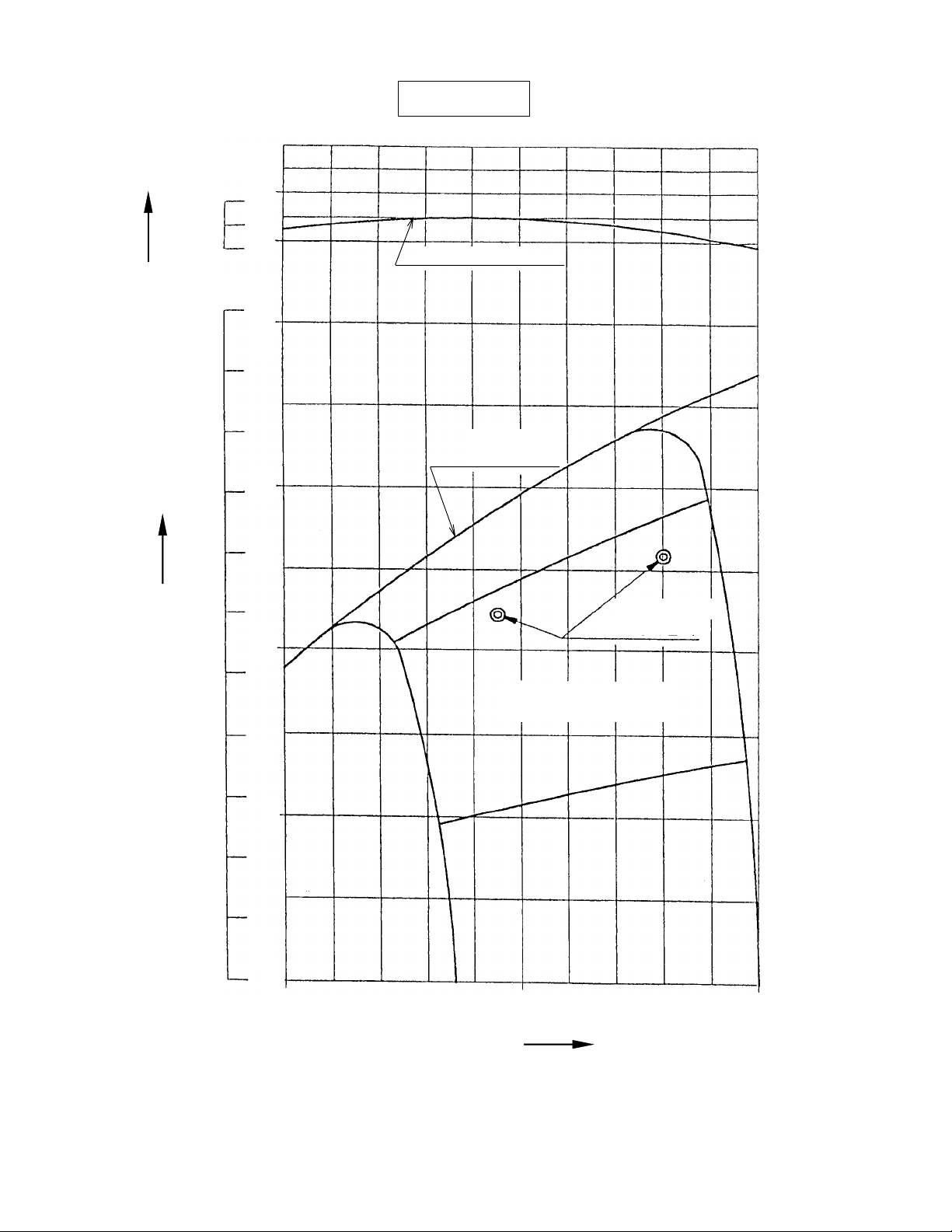
(kgf.m) N.m
EY20-3D
1.0
TORQUE
0.9
OUTPUT
10
9
(HP) kW
4
5
3
4
3
3
2
MAXIMUM TORQUE
MAXIMUM
HORSEPOWER
CONTINUOUS
RATED HP
2
1
0
1
0
2 0 0 0
RECOMMENDED
HORSEPOWER RANGE
3 0 0 0
REVOLUTION
4 0 0 0
r.p.m.
- 4 -
Page 8

3. FEATURES (compared with former model)
1. Re-designed outlook
Thinner recoil starter, newly designed air cleaner and muffler are adopted.
Also, innovate the image that express the reliability of Robin engine more by adopting new labels
and new color.
2. Shorter length increased mount-ability
Thinner recoil starter realized shorter length than former model. It eases to mount the engines to
many applications.
3. Development of dust proof air cleaner
Newly developed dual element air cleaner, which has bigger dust holding capacity, realized higher
reliability in dusty condition than former model.
4. Deep consideration on human and environment
New muffler realized quieter operation. Also, the engine meets with EPA Phase 1 exhaust emission
regulation, European emission gas regulations starting from 2002, and Japanese voluntary reguations
start from 2003, with dual element or cyclone type air cleaner.
5. Unchanged durability
Durability is the same as that of former model. Robin keeps producing reliable and dependable engine.
6. Parts interchangeability
Almost of all spare parts are interchangeable between new and former models. The air cleaner and
carburetor should be exchanged at the same time.
- 5 -
Page 9
4. GENERAL DESCRIPTION OF ENGINE COMPONENTS
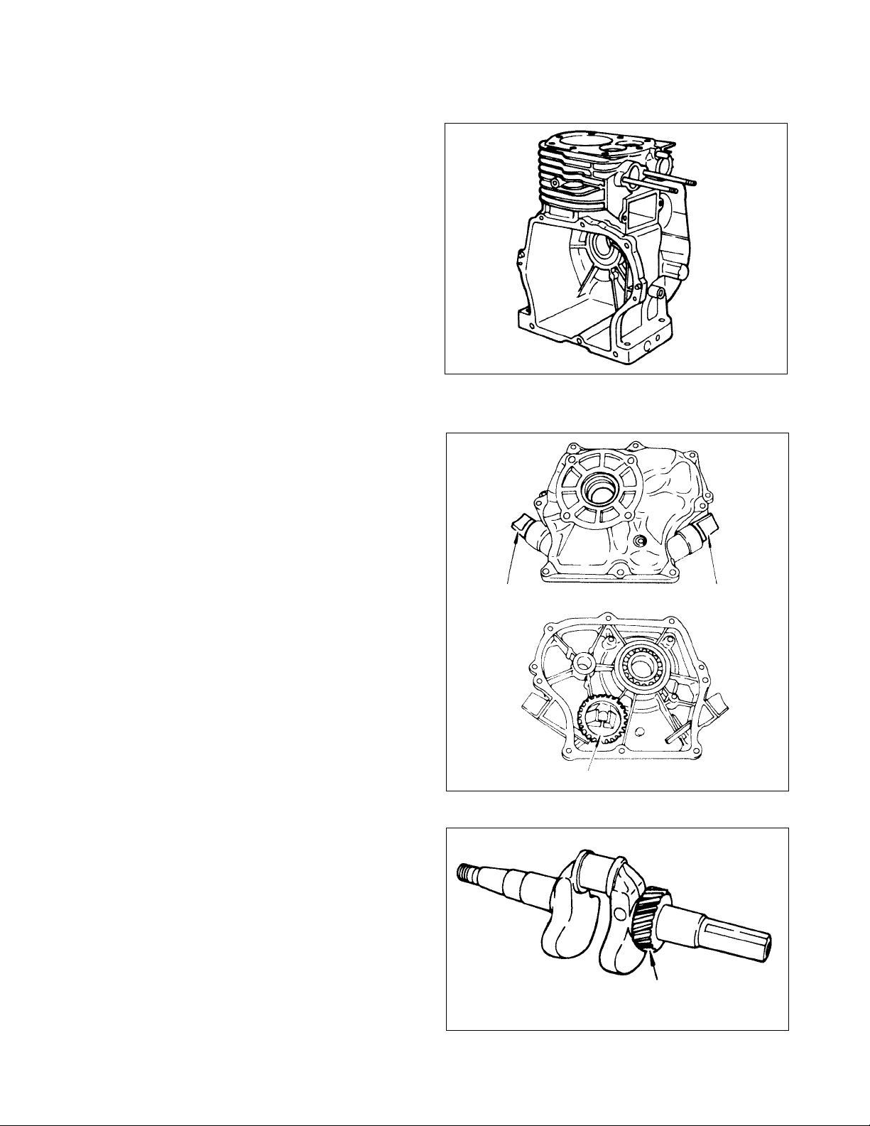
4-1 CYLINDER AND CRANKCASE
The cylinder and crankcase are single piece aluminum die-casting.
The cylinder liner, made of special cast iron, is
molded into the aluminum casting.
The intake and exhaust ports are located on one
side of the cylinder, and are also inserted into the
casting.
The crankcase has a mounting surface on the output shaft side, where the main bearing cover is
attached.
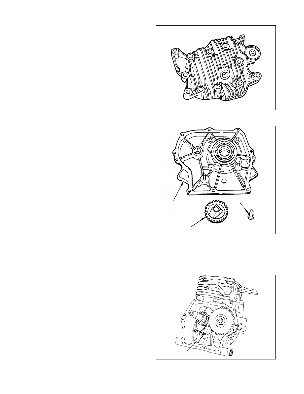
4-2 MAIN BEARING COVER
The main bearing cover is an aluminum die-casting, which is mounted on the output shaft side of
the crankcase.
Fig. 4-1
Remove the main bearing cover to inspect inside
of the engine.
Pilots and bosses are machined on the cover for
direct mounting of the engine onto such machines
as generators and pumps.
Oil gauges (fillers) are on both sides of the cover
for easy maintenance.
4-3 CRANKSHAFT
The crankshaft is forged carbon steel, and the
crank pin is induction-hardened.
The output end of the shaft has a crankshaft gear
that is pressed into position.
Oil Gauge Oil Gauge
Governor Gear
Fig. 4-2
- 6 -
Crank Gear
Fig. 4-3
Page 10
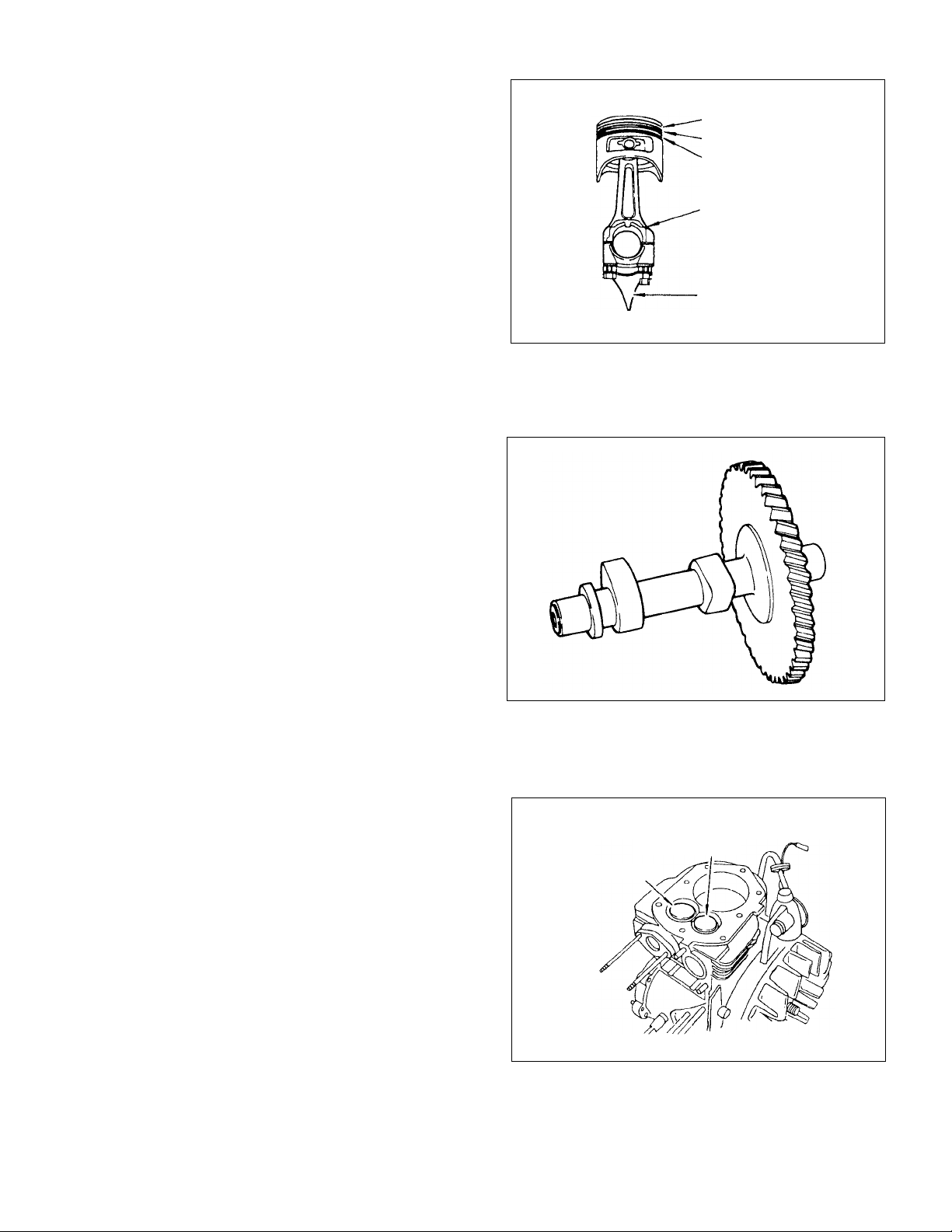
4-4 CONNECTING ROD AND PISTON
The connecting rod is forged of aluminum alloy,
and its large and small ends fanction as bearings.
The large end has a built-in oil scraper for splashing the lubricating oil.
The piston is an aluminum alloy casting, and carries two compression rings and one oil ring.
4-5 CAMSHAFT
The camshaft is made of special cast iron, and
camshaft and gear are cast together in one piece.
Both sides of the shaft fit into the plain bearings
on the crankcase and main bearing cover.
Top Ring
Second Ring
Oil Ring
Connecting Rod
Oil Scraper
Fig. 4-4
4-6 VALVE ARRANGEMENT
The exhaust valve is located upstream of the cooling air with the result that the exhaust valve is
intensively cooled for improved engine durability .
Fig. 4-5
Exhaust Valve
Intake Valve
Fig. 4-6
- 7 -
Page 11
4-7 CYLINDER HEAD
The cylinder head is an aluminum die-casting, and
forms a Ricardo type combustion chamber with
squish area for high combustion efficiency. The
spark plug is tilted for easy mounting of the fuel
tank.
4-8 GOVERNOR SYSTEM
The governor is a centrifugal flyweight type which
ensures constant operation at the selected speed
during load variations.
The governor gear with governor weights is installed on the main bearing cover.
Fig. 4-7
Main Bearing Cover
Governor Gear Complete
Fig. 4-8
Governor Sleeve
4-9 COOLING SYSTEM
The large fins on the flywheel provide sufficient cooling air capacity for the cylinder and cylinder head.
The cylinder baffle and head cover are provided for guiding the cooling air.
4-10 LUBRICATION SYSTEM
All the rotating and sliding parts are splash- lubricated by the oil scraper on the connecting rod.
- 8 -
Oil Scraper
Fig. 4-9
Page 12
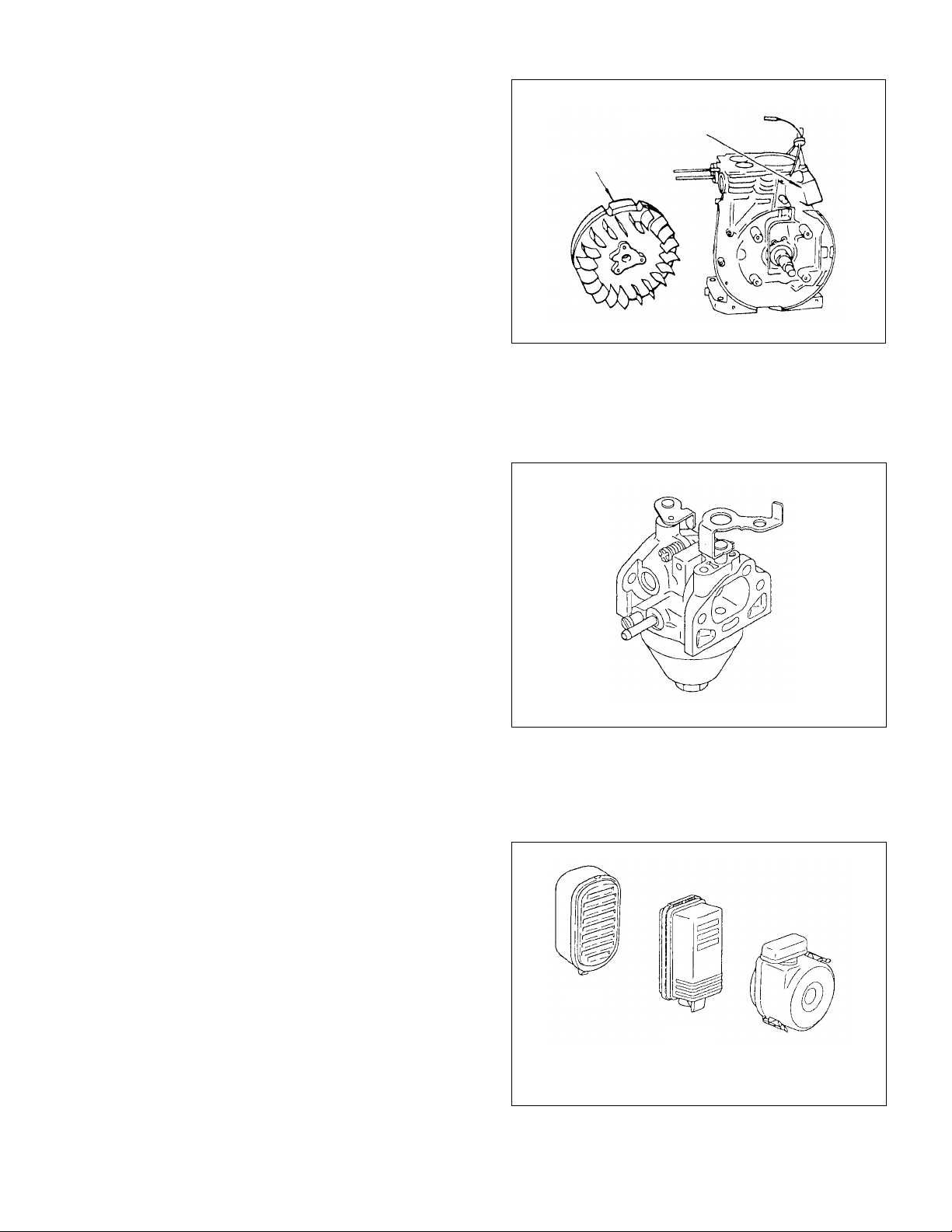
4-11 IGNITION SYSTEM
The ignition system is a transistor controlled magneto system which consists of a flywheel and an
ignition coil with a built-in transistor mounted on
the crankcase.
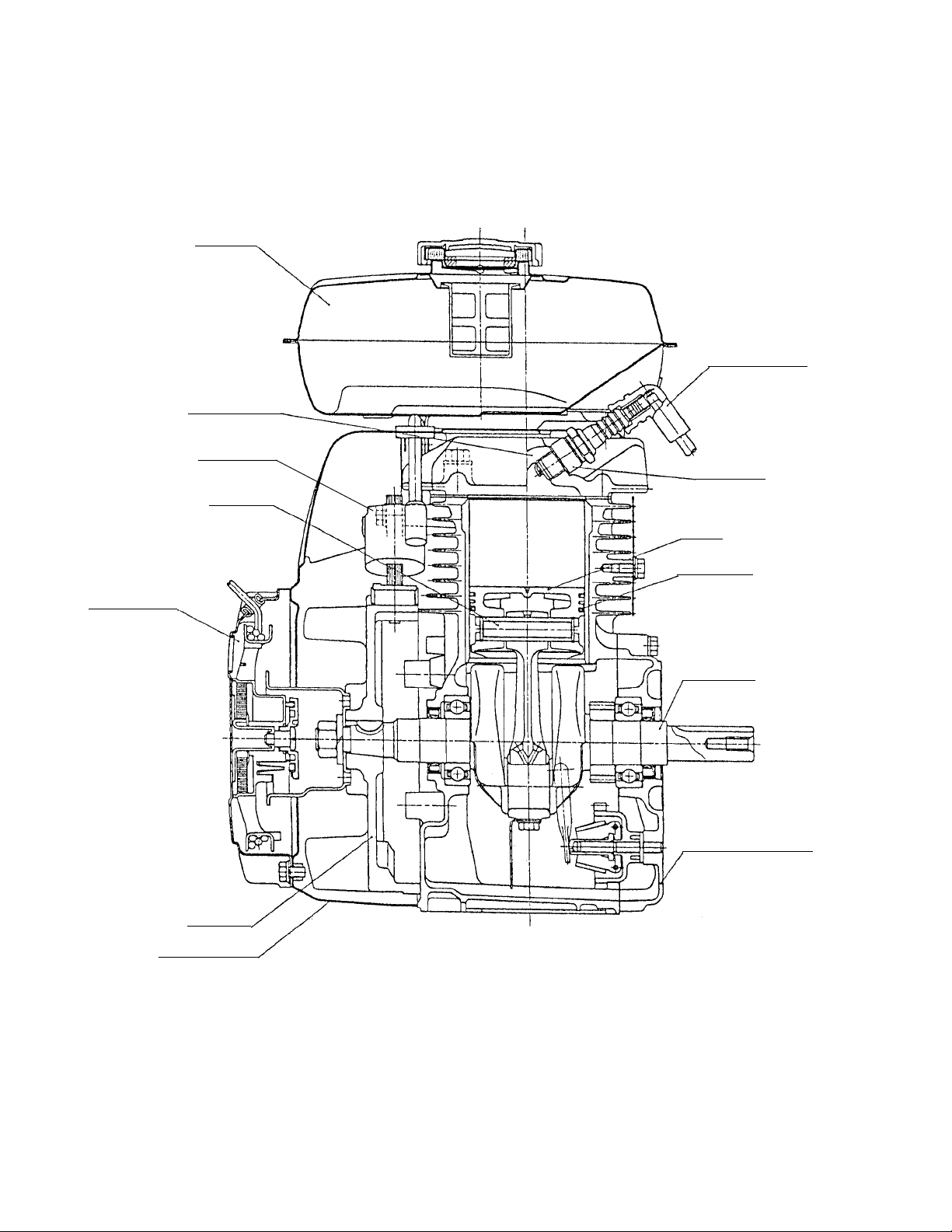
4-12 CARBURETOR
The engine is equipped with a horizontal draft carburetor that has a float controlled fuel system and
a fixed main jet.
The carburetors are calibrated carefully for sure
starting, good acceleration, less fuel consumption
and sufficient output.
Ignition Coil
Flywheel
Fig. 4-10
For details, refer to page 30, section “7 CARBURETOR”.
4-13 AIR CLEANER
The air cleaner of the standard engine is an oblong type using an urethane foam(semi-wet).
As optional parts,dual-element type and cyclone
chimney type are available.
STD type
Fig. 4-11
Dual-element type
(Option)
Cyclone chimney type
(Option)
- 9 -
Fig. 4-12
Page 13
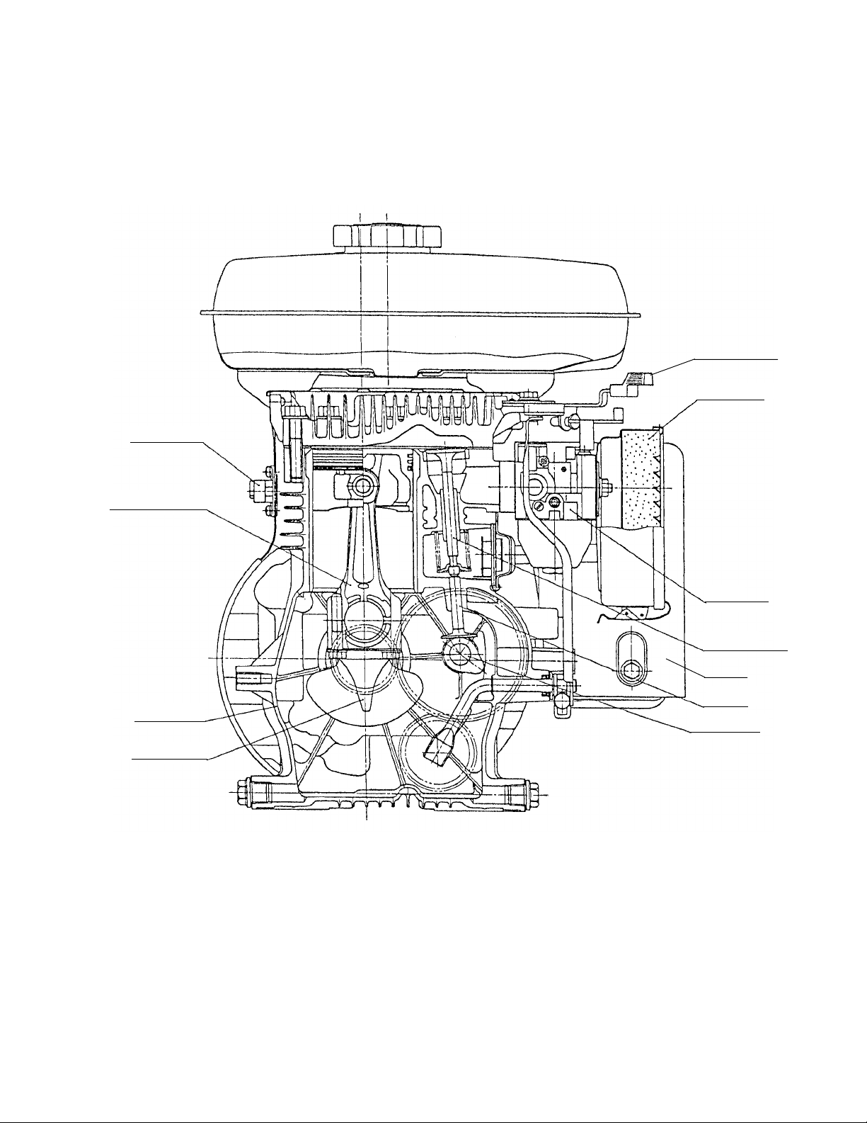
4-14 SECTIONAL VIEW OF ENGINE
Fuel Tank
Cylinder Head
Ignition Coil
Piston Pin
Spark Plug Cap
Spark Plug
Piston
Recoil Starter
Blower Housing
Piston Ring
Crankshaft
Main Bearing Cover
Flywheel
Fig. 4-13
-
10
-
Page 14
Stop Switch
Connecting Rod
Crankcase
Speed
Control Lever
Air Cleaner
Carburetor
Intake and
Exhaust Valve
Muffler
Tappet
Camshaft
Oil Scraper
Fig. 4-14
-
11
-
Page 15
5. DISASSEMBLY AND REASSEMBLY
5-1 PREPARATIONS AND SUGGESTIONS
1) When disassembling the engine, memorize the locations of individual parts so that they can be
reassembled correctly. If you are uncertain of identifying some parts, it is suggested that tags be
attached to them.
2) Have boxes ready to keep disassembled parts by group.
3) To prevent losing and misplacing, temporarily assemble each group of disassembled parts.
4) Carefully handle disassembled parts, and clean them with washing oil if necessary.
5) Use the correct tools in the correct way.
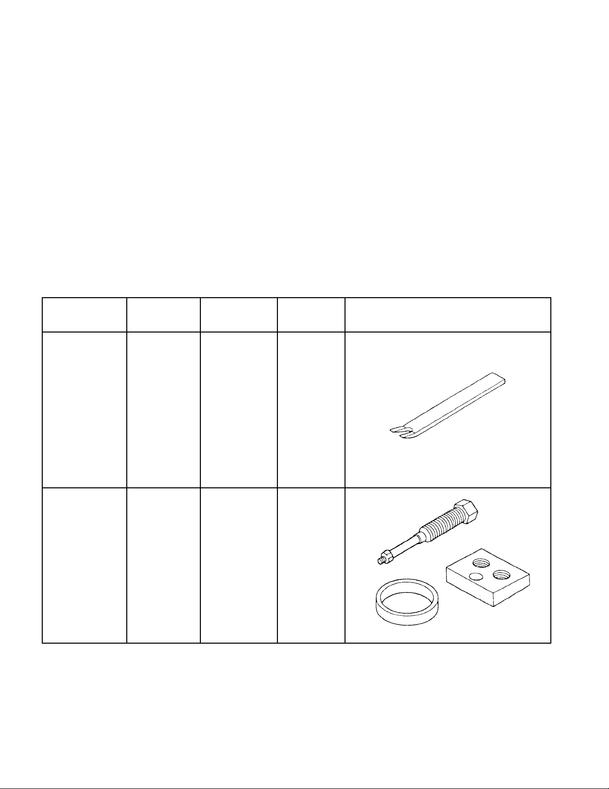
5-2 SPECIAL TOOLS
.oNtraPlooTesU
70-30059-722
70-10059-722
gnirpSevlaV
reniateR
ediuGevlaV
relluP
evlaVediuG
elbacilppA
ledoM
gnitnuomroF
gnirpSevlaV
dnareniateR
kcoLreniateR
ffognilluproF
82YE
41,31,01YE
02,81,51YE
72,52,32YE
02,51YE
epahS
1-5.giF
2-5.giF
-
12
-
Page 16
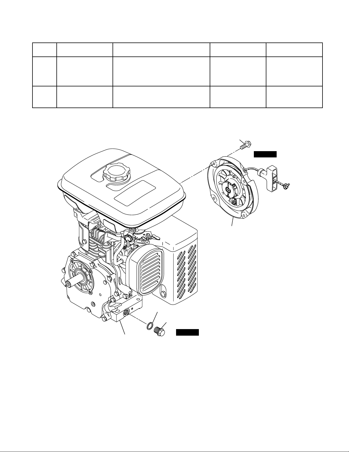
5-3 DISASSEMBLY PROCEDURES
petSevomerotstraPserudecorPskrameRlooT
gulPniarD)1(.lioenigneniarD
1
fosedishtobnosgulpniarD
ottonluferaceB
.teksagehtesol
rennapsxoBmm41
tloB21x41M.esacknarceht
2
.scp4:tlobegnalF8x6M
M6 x 8 Flange bolt : 4 pcs.
STEP 2
retratSlioceR)1(.retratsliocerevomeR
rennapsxoBmm01
STEP 2
Crankcase
Recoil Starter
Gasket
Drain Plug
STEP 1
Fig. 5-3
-
13
-
Page 17
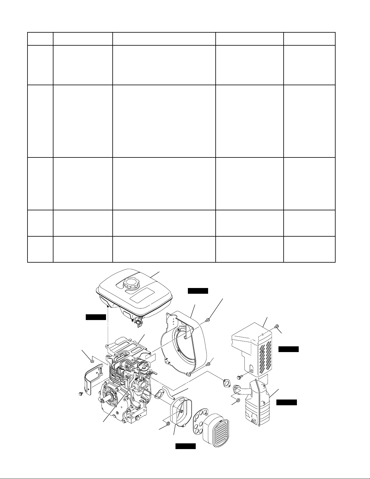
petSevomerotstraPserudecorPskrameRlooT
gnisuoHrewolB)1(gnisuohrewolbehtevomeR
ehtdnaesacknarcehtmorf
3
.daehrednilyc
signisuohrewolB
rehtegotdenetsaf
.knatleufehthtiw
rennapsxoBmm01
.scp2:tlobegnalF21x6M
.scp2:tlobegnalF41x6M
dnaknaTleuF
revoCdaeH
)1(
)2(
.kcocleufehtesolC
epipleufehttcennocsiD
rennapsxoBmm01
rennapSmm01ro
reniartsleufehtneewteb
leufehtmorfroterubracdna
4
)3(
.reniarts
morfknatleufehtevomeR
.daehrednilyceht
.scp2:tuN6M
)4(
revocdaehehtevomeR
.daehrednilycehtmorf
renaelCriA)1(
)2(
5
renaelcriaehtevomeR
.tnemelednarevoc
renaelcriaehtevomeR
siesacrenaelcriA
rehtegotdenetsaf
.roterubracehthtiw
.roterubracehtmorfesac
rennapsxoBmm01
.scp2:tuN6M
)3(
rehtaerbehttcennocsiD
.epip
revoCrelffuM)1(revocrelffumehtevomeR
6
.relffumehtmorf
rennapsxoBmm01
.scp3:tlobegnalF8x6M
relffuM)1(morfrelffumehtevomeR
7
ehtfonoitroprednilyceht
rennapSmm21
.scp2:tuN8M.esacknarc
Fuel T ank
STEP 4
M6 Nut : 2 pcs.
Head Cover
STEP 3
Blower Housing
Breather
Pipe
M6 x 14 Flange bolt : 2 pcs.
Muffler Cover
M6 x 12
Flange bolt
: 2 pcs.
M8 Nut :
2 pcs.
M6 x 8
Flange bolt : 3 pcs.
STEP 6
Muffler
STEP 7
Fig. 5-4
Fuel Pipe
M6 Nut : 2 pcs.
Air Cleaner
-
STEP 5
14
-
Page 18
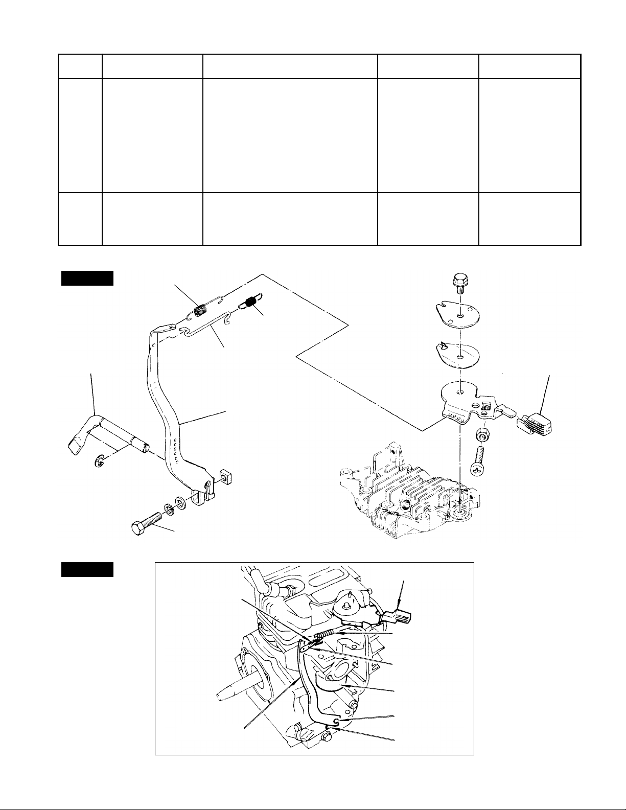
petSevomerotstraPserudecorPskrameRlooT
8
9
STEP 8
Governor Shaft
strap
roterubraC)1(morfroterubracehtevomeR
Governor Spring
reveLronrevoG
evitalerehtdna
Governor Rod
)1(
evomerdnatlobehtnesooL
ehtmorfrevelronrevogeht
.tfahsronrevog
.cp1:tloB52x6M
)2(
dorronrevogehtevomeR
.tlob
ehtnesooltsuJ
yrassecennu,tlob
ehttuoekatot
rennapsxoBmm01
rennapSmm01ro
ehtmorfgnirpsdordna
.roterubrac
ehtfonoitroprednilyceht
.esacknarc
Rod Spring
Speed Control Lever
STEP 9
Governor Lever
Fig. 5-5
M6 x 25 Bolt : 1 pc.
Speed Control Lever
Rod Spring
Governor Spring
Governor Rod
Carburetor
Governor Lever
Governor Shaft
Bolt
-
15
-
Fig. 5-6
Page 19
petSevomerotstraPserudecorPskrameRlooT
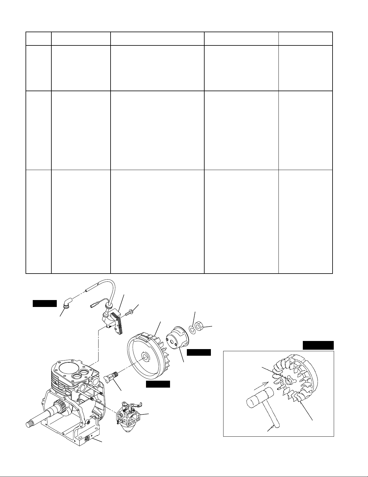
lioCnoitingI)1(gulpkrapsehtevomeR
tlobsmeS
rennapsxoBmm01
,gulpkrapsehtmorfpac
01
noitingiehtevomerdna
.esacknarcehtmorflioc
.scp2:tloB52x6M
yelluPgnitratS)1(gnitratsehtevomeR
.leehwylfehtmorfyellup
.cp1:tuN41M
tekcosroxobatiF
11
leehwylfehtrevohcnerw
drahtiekirtsdna,tun
ottonluferaceB
fosedalbehtegamad
ahtiwleehwylfeht
ekirtS.ekiladnarevird
htiwesiwkcolcretnuoc
.remmaha
rennapsxoBmm91
hcnerwtekcoSro
otremmahahtiw
)mm41(tunehtevomer
.rehsawgnirpsdna
leehwylF)1(
)1(
ehtelbmessayllaropmeT
ehtottungnixif
litnudaerhttfahsknarc
)2(
.ecafdneeht
)2(
21
ahtiwtungnixifehtpaT
otremmahcitsalP
.leehwylfehtevomer
.remmah
yltceridpattonoD
.remmahleetsahtiw
ottonluferaceB
daerhtehtegamad
gnisunehwnoitrop
.remmahleetsa
tungnixifehtpaT
gnitresniretfa
rabmunimula
gnixifehtneewteb
leetsadnatun
STEP 10
Spark Plug Cap
Ignition Coil
Crankshaft
Crankcase
M6 x 25 Bolt : 2 pcs.
Flywheel
STEP 12
Carburator
Fig. 5-7
-
Spring Washer
STEP 11
Starting Pulley
16
-
M14 Nut : 1 pc.
STEP 12
Fixing Nut
Flywheel
Hammer
Fig. 5-8
Page 20

petSevomerotstraPserudecorPskrameRlooT
gulPkrapS)1(gulpkrapsehtevomeR
31
daeHrednilyC)1(
.daehrednilycehtmorf
dnatlobmm8ehtevomeR
rennapsxoBmm12
rennapsxoBmm21
daehrednilycehtevomer
41
)2(
.esacknarcehtmorf
.scp8:tloB04x8M
daehrednilycehtevomeR
.esacknarcehtmorfteksag
dnaekatnI
evlaVtsuahxE
51
)1(
revocteppatehtevomeR
morfetalprehtaerbehtdna
.esacknarceht
.scp2:tloB21x6M
)2(
dnaekatniehttuolluP
.edis
.evlavtsuahxe
)3(
gnirpsevlavehtevomeR
.reniaterevlavehtdna
.uoy
gniraeBniaM
revoC
)1(
fotlobgnixifehtevomeR
morfrevocgniraebniameht
ehtnohctonehttuP
foecnerefmucricretuo
sihtnoreniatergnirpseht
)-(ezismuidemehtkooH
rewol(tnedehttarevird
gnirpsehtfo)edis
ehttuollupdnareniater
ehtgnillupelihw,sevlav
drawotreniatergnirps
.edis
revirD)-(
rennapsxoBmm01
sihtsitnorfehT
rennapsxoBmm01
.esacknarceht
61
)2(
.scp8:tloB03x6M
ylthgil,revocehtevomeR
ylneverevocehtgnippat
ottonluferaceB
.laeslioehtegamad
.remmahcitsalpahtiw
M8 x 40 Bolt : 8 pcs.
STEP 13
Spark Plug
Main Bearing Cover
STEP 16
Oil Gauge
M6 x 30 Bolt : 8 pcs.
STEP 14
Crankcase
Fig. 5-9
Cylinder Head
Intake & Exhaust Valve
STEP 15
Breather Plate
Tappet Cover
Drain Plug
M6 x 12 Bolt : 2 pcs.
-
17
-
Page 21

Push the Valve
(-) Driver
Plastic Hammer
Fig. 5-10 Fig. 5-11
Polyvinyl tape
Main Bearing Cover
petSevomerotstraPserudecorPskrameRlooT
71
81
Intake Valve
tfahsmaC)1(morftfahsmacehtevomeR
teppaT)1(morfsteppatehtevomeR
Exhaust Valve
Valve Spring
Spring Retainer
Tappet
STEP 18
steppatehttneverpoT
.esacknarceht
,gnigamadrognillafmorf
ehtotesacknarcehttup
.nwodedisleehwylf
atup,gnivomererofeB
.esacknarceht
tsuahxeroekatnifokram
.teppathcaeno
Camshaft
Governor Gear
Fig. 5-12
STEP 17
Camshaft
Tappet
Fig. 5-13
-
18
-
Page 22

petSevomerotstraPserudecorPskrameRlooT
doRgnitcennoC
notsiPdna
)1(
rehtodnanobracffoeparcS
reppuehtmorfstisopedngierof
,notsipdnarednilycehtfostrap
mm01
rorennapsxoB
rennapSmm01
foseceipowtevomernehtdna
.tlobdorgnitcennoc
)2(
91
dnareparcslioehtevomeR
ehtmorfpacdorgnitcennoc
.tfahsknarc
)3(
ehtlitnutfahsknarcehtnruT
daedpototsemocnotsip
gnitcennoctuohsupdna,retnec
ehtmorfylbmessanotsipdnador
.rednilycfopot
gniRdnanotsiP)1(
ehttuollup,spilcowtehtevomeR
ffonotsipehtekatdna,nipnotsip
ehtfodnellamsehtmorf
02
)2(
.dorgnitcennoc
ehtfosdnenepoehtdaerpS
mehtevomerdnasgnirnotsip
.notsipehtmorf
ottonluferaceB
ybsgnirehtkaerb
ootgnidaerps
.hcum
tfahsknarC)1(
ehtrof(yekffurdoowehtevomeR
.)otengam
12
)2(
fodneleehwylfehtnoylthgilpaT
.laes
ottonluferaceB
lioehtegamad
otremmahtfosahtiwtfahsknarc
.esacknarcmorftievomer
Clip
Piston Pin
Woodruff Key
STEP 20
STEP 19
Piston Ring
Piston
Connecting Rod
STEP 21
Crankshaft
Fig. 5-14
Oil scraper
Connecting Rod Bolt : 2 pcs.
-
19
-
Page 23

5-4 REASSEMBLY PROCEDURES
● PRECAUTIONS FOR REASSEMBLY
1) Clean parts thoroughly before reassembly.
Pay most attention to cleanliness of piston, cylinder, crankshaft, connecting rod and bearings.
2) Scrape off all carbon deposits from cylinder head, piston top and piston ring grooves.
3) Check lip of oil seals. Replace oil seal if the lip is damaged. Apply oil to the lip before reassembly .
4) If the gasket is stuck on the mount ing surface, remove it carefully by ta king care not to damage the
surface.
5) Replace all the gaskets with new ones.
6) Replace keys, pins, bolts, nuts, etc., if necessary.
7) Torque bolts and nuts to specification refer to the "TORQUE SPECIFICATIONS" (See page 56).
8) Apply oil to rotating and sliding portions.
9) Check and adjust clearances and end plays where specified in this manual.
10) When the main parts are assembled, check the movement and sound by rotating it manually .
5-4-1 CRANKSHAFT
(1) Insert crankshaft in ball bearing of crankcase
wrapping the key-way with polyvinyl tape to
avoid damage to oil seal.
(2) Install woodruff key for flywheel on crankshaft.
5-4-2 PISTON AND PISTON RINGS
1) If no ring expander is available, install the ring
by placing the open end over the first land of
the piston, and spreading the ring only far
enough to slip it over the correct ring groove.
NOTE : Pay attention not to break the rings by
twisting. Install the oil ring first followed by the
second ring and then top ring. The surfaces of
the second ring and the top ring with marks are
to be faced up.
Crankshaft
Polyvinyl tape
Fig. 5-15
Open End of
Piston Ring
Fig. 5-17
-
20
-
Page 24

3-51YE3-02YE
gniRpoT
lerraB
ecaF
repaT
dna
gniRdnoceStuCrednUrepaT
gniRliO
gniRrettuC
rednapxElioChtiw
Table. 1
2) Reassemble the piston and connecting rod with the piston pin.
NOTE :Apply enough oil to the small end of the connecting rod. Be sure to place the clips on both
sides of the piston pin.
3) When installing the connecting rod assembly
into the cylinder, hold piston rings with the ring
guide as shown in Fig.5-18 (if no ring guide is
available, keep pressing the piston rings with
Connecting Rod
Piston Ring Guide
Mark
finger tips and gently strike the top of the piston with a plastic hummer or the like to push it
in), and check that the symbol or mark MAG
on the connecting rod is to face the flywheel
magneto side.
Crankcase
(Magneto Side)
levebrennl
NOTE : Apply enough oil to the piston rings,
connecting rod plain bearings and cylinder bore
Fig. 5-18
before assembly.
NOTE : The open ends of the piston rings must be 90°apart from each other before assembly.
5-4-3 CONNECTING ROD
1) Turn the crankshaft to the bottom dead center, lightly tap the piston head until the large end of connecting rod contacts the crankpin.
2) When reassembling the connecting rod cap,
match the alignment projection mark on the rod.
3) Oil scraper is to be set on the magneto side.
NOTE : After reassembly, confirm that the con-
necting rod moves lightly.
NOTE : Connecting rod cap tightening torque :
EY15-3 EY20-3
9-11.5N.m 17-22N.m
(90-115kg.cm) (170-200kg.cm)
(6.5-8.3ft.lb) (12.3-14.5ft.lb)
Alignment Mark
Fig. 5-19
Oil Scraper
-
21
-
Page 25

5-4-4 TAPPET AND CAMSHAFT
Insert the tappets into the crankcase holes first,
and then mount the camshaft.
NOTE : Align the timing mark on the root of the
cam gear with the one on the crank gear. If the
valve timing is wrong, the engine cannot operate
properly or at all.
NOTE : If the intake tappet and exhaust tappet
were assembled opposite each other, the tappet
clearance cannot be kept correctly.
Timing Mark
Timing Mark
5-4-5 MAIN BEARING COVER
Fig. 5-20
Install the main bearing cover to the crankcase.
NOTE: As the governor gear is mounted on the main bearing cover side, install the main bearing cover
with checking that the governor gear meshes with the cam gear. (See Fig.5-21&22.) If the oil seal needs
to be replaced, press-fit a new oil seal before installing the main bearing cover.
Pay attention to the engagement of
the governor gear and cam gear
Governor Gear
Fig. 5-21
Fig. 5-22
NOTE: When installing the main bearing cover,
apply oil to the bearing and oil seal lip. Wrap the
keyway of crankshaft with polyvinyl tape to avoid
damage to the oil seal lip. Then place the main
bearing cover on.
Check that the crankshaft side clearance is 0〜
0.2mm; and if not, adjust it with the adjusting
shims.
Main Bearing Cover Tightening torque
8-10N・m
(80-100kg・cm)
(5.8-7.2ft・lb)
-
22
Adjusting Shim
Main Bearing Cover
Polyvinyl tape
Packing
Fig. 5-23
-
Page 26

NOTE: Fig 5-24 shows one of the methods measuring the crankshaft side clearance between the
machined face of the crankcase and shims. As a
paper packing is used on the machined face of
the crankcase, adjust the clearance by taking this
thickness of 0.22mm into account.
Dial Indicator
Ground Surface of Crankcase
5-4-6 INTAKE AND EXHAUST VALVES
Fig. 5-24
Remove carbon and gum deposite from the valves, valve seats, intake and exhaust ports and valve
guides.
NOTE: If the valve face is dinted or warped, replace the valve with new one.
NOTE: If there is an excessive clearance between the valve guide and valve stem, replace the valve
guide with a spare. For replacing, pull out the valve guide, using the valve guide puller as shown in Fig.
5-26, and press fit a new valve guide into place.
Valve Guide Puller
Valve Guide Puller
Crankcase
Valve Guide
Fig. 5-25
Fig. 5-27
Valve Guide
Fig. 5-26
ELGNAECAFEVLAV-A °54
ELGNATAES-B °54
.AIDEDISNIEDIUG-C
EKATNI
.AIDEDISTUOMETSEVLAV-D
TSUAHXE
ELBAWOLLAMUMIXAM
DdnaCNEEWTEBECNARAELC
ELGNATLITMETSEVLAV-E"35°3
EKATNIL260.0~L520.0
TSUAHXEL001.0~L650.0
Table. 2
-
23
-
Nut
3-02YE3-51YE
220.0+.aid5.6
0
520.0-.aid5.6
040.0-
650.0-.aid5.6
870.0-
L : LOOSE
Page 27

5-4-7 TAPEET ADJUSTMENT
Lower the tappet all the way down, push the valve, and insert a thickness gauge between the valve and
tappet stem to measure the clearance. (See Fig.5-28.)
NOTE: The correct tappet clearance for both intake and exhaust valves is 0.1mm ±0.02mm when the
engine is cold.
Valve Spring
Thickness Gauge
(0.1mm ±0.02)
Valve
Tappet
Fig. 5-28 Fig. 5-29
Intake, Exhaust Valve
Spring Retainer
NOTE: If the clearance is smaller than specified, slightly grind the top of the valve stem, and measure it
again. On the contrary if the clearance is too large, replace the valve with new one, and polish its contact
surface with a compound to obtain a good fit. Then adjust the clearance.
NOTE: After the tappet clearance adjustment, install the valve springs and spring retainers, and turn the
crankshaft, and measure the tappet clearance once again if it is correct.
NOTE: INSTALLATION of SPRING RETAINERS
Place the notch on the outer circumference of the spring retainer toward this side and insert the retainer,
like pushing in, using a special tool. (Valve Spring Retainer)
(-) Driver
Front should be this side
Valve Spring Retainer
Fig. 5-30
Fig. 5-31
-
24
-
Page 28

k
5-4-8 CYLINDER HEAD
Remove carbon from the cylinder head, particularly its combustion chamber, and clean the cooling fins.
Also check the head surface for flatness.
If the gasket is stuck on the upper surface of crankcase and on the cylinder head, separate it carefully by
taking care not to damage the mating surface.
NOTE: Replace the cylinder head gasket with a new one.
NOTE: DISTINGTION between the GASKET of EY 15-3 and EY20-3
The pitch of the mounting holes and the outer circumference dimensions of the gasket for EY15-3 and
EY20-3 are same. However, the inner dimensions are different each other.
Furthermore, the marking is provided at the position shown below for identification.
15
EY15-3
"15" mark "20" mar
Fig. 5-32
With 8 pieces of 8mm bolt fasten the cylinder head.
Cylinder Head Tightening torque
22-26N・m
(220-260kg・cm)
(15.9-18.8ft・lb)
NOTE: DISCRIMINATION of CYLINDER HEAD
As stated above, the pitch of the holes of cylinder
head is common to both EY15-3 and EY20-3. For
enabling to discriminate the cylinder head of EY153 from that of EY20-3, an embossed mark 15 is
given to the EY15-3 cylinder head, while no embossed mark is given to the EY20-3 cylinder head.
NOTE: Embossed mark for
EY15-3 Kerosene engine is 15-K, and
EY20-3 Kerosene engine is 20-K.
20
EY20-3
Embossed mark
Fig. 5-33
5-4-9 SPARK PLUG
Install spark plug to cylinder head.
Spark plug : NGK B6HS or BR6HS
NEW SPARK PLUG RETAIGHTENING
12-15N・m 23-27N・m
(120-150kg・cm) (230-270kg・cm)
(8.7-10.8ft・lb) (16.6-19.5ft・lb)
-
25
-
Page 29

5-4-10 IGNITION COIL, FLYWHEEL AND STARTER PLLEY
Fit the flywheel on to the crankshaft.
Also, fasten the starter pulley together with the flywheel.
NOTE: Before installing, wipe out oil from the crankshaft and the tapered portion of the flywheel.
Flywheel Tightening torque
60-65N・m
(600-650kg・cm)
(43.4-47.0ft・lb)
Ignition Coil
Fasten the ignition coil to the crankcase temporarily and adjust air gap between the ignition coil and the flywheel, then fasten the ignition coil tightly.
Air gap: 0.3 ~ 0.5mm
Thickness Gauge
5-4-11 CARBURETOR
Fig. 5-34
To the cylinder portion of the crankcase, install the gasket, insulator, gasket and carburetor in order , and
then mount the air cleaner case and fasten them with two pieces of 6mm nut.
(0.5mm)
5-4-12 GOVERNOR LEVER
When reassembling, refer to the 6. GOVERNOR ADJUSTMENT.
5-4-13 MUFFLER AND MUFFLER COVER
If the muffler gasket is stuck to the crankcase and to the muffler flange surface, remove it carefully by
taking care not to damage the surfaces.
Be sure to replace the muffler gasket with a new gasket.
Install the muffler to the cylinder with 2 pieces of stainless steel nuts, then mount the muffler cover.
5-4-14 HEAD COVER, FUEL TANK AND BLOWER HOUSING
Install the head cover, fuel tank and blower housing in order.
NOTE: If these parts are installed in the order of the head cover, blower housing and fuel tank, removal
of the blower housing would be impossible.
5-4-15 RECOIL STARTER
Fasten the recoil starter with 4 pieces of M6 x 8 mm bolt.
NOTE: It is feared that the bolt longer than 8mm may damage the blades.
Install the plastic recoil for the pump specification of model EY15-3 with 4 pieces of
M6 x 12 mm bolt.
-
26
-
Page 30

5-5 BRAKE-IN OPERATION OF REASSEMBLED ENGINE
An overhauled engine must be operated at low speed to break-in the parts. A thorough break-in is indispensable particularly when the cylinder, piston, piston rings or valves are replaced with new ones.
The recommended break-in schedule is shown below.
petSdaoLdeepSenignEemiT
1petS daoLoNmpr005,2.nim01
2petS daoLoNmpr000,3.nim01
3petS daoLoNmpr006,3.nim01
3-51YE)PH53.1(Wk0.1
4petS
mpr006,3.nim03
3-02YE)PH57.1(Wk3.1
3-51YE)PH7.2(Wk0.2
5petS
mpr006,3.nim06
3-02YE)PH5.3(Wk6.2
Table. 3
-
27
-
Page 31

6. GOVERNER ADJUSTMENT
Models EY15-3 and EY20-3 employ a centrifugal flyweight type governor. The governor is mounted on
the governor gear and the throttle valve of the carburetor is automatically regulated by a lever which is
connected to the governor in order to maintain constant engine speed against load variations.
The adjustment procedure of the governor is as follows (See Figs. 6-1 and 6-2.):
1) Connect the carburetor throttle lever to the
governor lever with the governor rod and rod
spring, and mount the governor lever onto the
governor shaft.
2) Install the speed control lever to the cylinder
head.
3) Connect the governor lever to the speed control lever with the governor spring.
Speed Control Lever
Long Hook
High Speed
Rod Spring
Governor Lever
Speed Control
Lever
Governor
Spring
Governor
Rod
Carburetor
Governor
Shaft
Bolt
Fig. 6-1
Governor Spring
Governor Lever
Fig. 6-3
*The hole where the governor spring is to be
hooked :
For EY15-3 the governor spring is to be hooked
to the hole 1, while it is to be hooked to the hole 2
for EY20-3.
4) Turn the speed control lever towards high
speed, and confirm that the carburetor throttle
valve is fully opened.
-
5) Insert a (
) screwdriver in the groove of the
governor shaft, turn it clockwise fully until the
governor shaft no longer moves, and then lock
the governor lever to the governor shaft with
the governor lever tightening bolt.
(See Fig.6-4)
Low Speed Stopper
(Carburetor)
Governor Lever
High Speed Stopper
(Speed Control Lever)
Fig. 6-2
Fig. 6-4
-
28
-
Page 32

*Dimensions of the governor spring for the engine to be connected to the generator:
The dimensions of the governor spring to be used are different each other according to the Hz.
The governor spring for the standard engine is same as that for the engine to be connected to the 60Hz
generator.
Discrimination according to the dimensions:
EY15-3/60Hz (Standard)
(a) 10 mm
(Longer Hook Side)
EY20-3/60Hz (Standard)
(a) 10 mm
(Longer Hook Side)
Fig. 6-5
EY15-3/50Hz
(A) 15 mm
(Longer Hook Side)
EY20-3/50Hz
(A) 15 mm
(Longer Hook Side)
*For EY15-3 and EY20-3, the governor spring longer in the length of (A) is for 50 Hz.
*Both ends of the spring for EY15-3 are bended to the same direction, while both ends of the spring for
EY20-3 are bended to contrary directions.
-
29
-
Page 33

7. CARBURETOR
7-1 OPERATION AND CONSTRUCTION (See Fig.7-1)
7-1-1 FLOAT SYSTEM
The float chamber is located just below the carburetor body, and the float (F) and the float valve (F.V)
maintain a constant fuel level during engine operation.
The fuel flows from the fuel tank into the float chamber through the float valve. When the fuel rises to a
specific level, the float (F) rises; and when its buoyancy and fuel pressure are balanced, the float valve
(F.V) close to shut off the fuel, thereby keeping the fuel at the reference level.
Slow Port
(S.P)
Idle Port
(I.P)
Slow Jet
(S.J)
Slow Air Bleed
(S.A.B)
Main Nozzle
(M.N)
Main Air Bleed
(M.A.B)
Choke
(C)
Throttle Valve
(T.H.V)
燃料Fuel
Float Valve
(F.V)
Main Jet
(M.J)
Fig. 7-1
-
30
Float
(F)
-
Page 34

7-1-2 SLOW SYSTEM
The pilot system feeds the fuel to the engine during idling and low-speed operation.
The fuel is fed through the main jet (M.J) to the slow jet (S.J), where it is metered, and mixed with the air
metered by the slow air bleed (S.A.B).
The fuel-air mixture is fed to the engine through the idle port (I.P) and slow port(S.P).
During engine idling, the fuel is mainly fed from the idle port (I.P).
7-1-3 MAIN SYSTEM
The main system feeds the fuel to the engine during medium and high-speed operation.
The fuel is metered by the main jet (M.J) and fed to the main nozzle (M.N). The air metered by the main
air bleed (M.A.B) is mixed with the fuel through the bleed holes in the main nozzle (M.N), and the mixture
is atomized out of the main bore. It is mixed again with the air taken through the air cleaner into an
optimum fuel-air mixture, which is supplied to the engine.
7-1-4 CHOKE
The choke (C) is used for easy start in the cold season. When the recoil starter is pulled with a closed
choke (C), the negative pressure applied to the main nozzle increases and draws much fuel accordingly;
thus easily start up the engine.
7-2 DISASSEMBLY AND REASSEMBLY (See Fig.7-2)
Apart from mechanical failures, most of carburetor troubles are caused by an incorrect mixing ratio,
which may arise mainly due to a clogged up air or fuel passage in jets, or fuel level variations. In order to
assure proper flow of air and fuel, the carburetor must be kept clean at all times. The carburetor disassembly and reassembly procedures are as follows.
-8
-22
-11
-32
-4
-3
-61
-15
-14
-18
-19
7-2-1 THROTTLE SYSTEM
(1) Remove the Philips screw (-2) and throttle
valve (-1), and pull out the throttle shaft (-1 1).
When reassemble the throttle valve, apply a
screw-lock agent to philips screw and tighten
it with a tightening torque of 0.39~1.47 N・m
(4~15 kg・cm) (0.3~1.1ft・lb).
(2) The spring (-41) can be taken out by removing
the throttle stop screw (-40).
*Exercise care not to damage throttle valve edge.
7-2-2 CHOKE SYSTEM
-40
-2
-1
-41
-5
(1) Remove the clip (-4) and choke valve (-3), and
pull out the choke shaft (-8).
(2) When mounting the choke valve, mark sure
that the cutout of the choke valve locates on
the right side when viewed from the outside.
-
31
-16
-17
-12
Fig. 7-2
-
Page 35

7-2-3 SLOW SYSTEM
(1) Remove the slow jet (-5), using correct tool to avoid damage to it.
(2) When fitting the slow jet, screw it in fully and turn it back, accurately by the rotation specified in the
table of correction standards.
7-2-4 MAIN SYSTEM
(1) Remove the bolt (-12) and take out float chamber body (-16).
(2) Remove the main jet (-22) from the body.
(3) Fasten the main jet securely to the body . Otherwise, the fuel may become too rich and cause engine
malfunction.
Main jet Tightening torque
0.98-2.94N・m
(10-30kg・cm)
(0.7-2.1ft・lb)
(4)
Bolt(-12) Tightening torque
7.85-11.77N・m
(80-120kg・cm)
(5.8-8.7ft・lb)
7-2-5 FLOAT SYSTEM
(1) Pull out the float pin (-15) and remove the float (-19) and float valve (-14).
CAUTION :
When cleaning the jets, use neither a drill nor a wire (because of possible damage of the
orifice which will adversely affect fuel flow). Be sure to use compressed air to blow them
clean.
NOTE ; Check that the gasket (float chamber) is correctly fitted before mounting the float chamber body.
-
32
-
Page 36

8. MAGNETO
8-1 FEATURES
Ignition system of the model EY15-3 and EY20-3 is a maintenance-free electronic pointless magneto
system.
The electronic circuit is based on the cut off of the electric current by power transistor, and employs
U.T.C.I. (Universal Transistor Control Ignition) circuit which always controls the ignition voltage to maximum.
Thanks to the U.T.C.I., the ignition performance is always stable against environmental changes such as
temperature, etc..
8-2 BASIC PRINCIPLE OF U.T.C.I.
ROBIN electronic ignition system consists of the
ignition coil with built-in U.T.C.I. circuit and the flywheel magnet.
(1) When the flywheel rotates and the magnet
passes the ignition coil, magnetic flux changes
to induce voltage across the primary ignition
coil.
Resultant electric current in the primary coil
is switched by power transistor in the circuit.
(2) When the flywheel rotates further to the igni-
tion timing, ignition timing detection circuit is
activated to turn on the thyristor which cut off
the current to the power transistor suddenly.
The U.T.C.I. controls to cut off the current induced in the primary always at around the
maximum level.
(3) Sudden cut off of primary current induces a
high voltage across the secondary coil to
spark the spark plug.
Spark Plug
Secondary Coil
Spark Plug
Flywheel
Primary Coil
Stop Switch
Fig. 8-1
BLACK
Ignition Coil
Oil Sensor
Fig. 8-2
Ignition timing
detection circuit
Thyristor
Power transistor
Stop Switch
-
33
-
Page 37

8-3 MAGNETO TROUBLESHOOTING
When the engine does not start or starts with difficulty, or when its operation is unstable, the following
checks will clarify if they are caused by a defect of the magneto.
(1) Check ignition cable for possible damage, worn insulator or loose connection.
(2) Check the spark.
1) Remove the spark plug from the cylinder head and connect the spark plug to the plug cap, then
ground it to the cylinder head or the like (The correct gap of electrodes is 0.6 ~ 0.7mm).
2) Pull the recoil starter to rotate the flywheel to check the spark of the spark plug and spark intensity
(disconnect primary wiring at the connector before the test).
3) If no spark is found between the plug electrodes, remove both the plug and the plug cap and place
the tip of ignition (high voltage) cable a few mm away from the cylinder head to check the spark
from the cable tip when the recoil starter is pulled.
-
34
-
Page 38

9. OIL LEVEL SENSOR (OPTION)
9-1 FUNCTION
When the oil level sensor detects the insufficient level of engine oil, it halts engine for warning and
protection of engine.
9-2 PRINCIPLE
(1) Though it is very little, engine oil has electrical conductivity, while air is completely nonconductive.
Utilizing this difference, presence of oil is identified by the current between electrodes of the sensor .
(2) On the basis of this principle the sensing elements are merely fixed electrodes without mobile part,
hence, it is possible to conduct reliable measurement without influence of vibration. And it is also
shockresistant and free of deterioration.
Outer electrode
Inner electrode
Conduction
-
Fig. 9-1
35
-
In case of no oil
Page 39

10. RECOIL STARTER
10-1 RECOIL STARTER (STEEL)
Tools to be prepared: Driver, Pinchers (Pliers) and Protective Glasses
WARNING
Before starting the disassembly, make sure to wear the protective glasses.
10-1-1 DISASSEMBLY STEPS
(1) Relieve the spring power
-1: Hold the starter knob and extract the starter
rope.
-2: Extract the rope fully and hold the rope so
that the knot of the rope in the reel makes
a straight line with the rope guide.
-3: Hold the reel with the thumbs of both hands
firmly so that the rope will not be wound
back. (Fig.10-1)
-4: Pull out the knot of the rope out of the reel,
and unfasten the knot and pull it out toward
the starter knob. (2 people required)
-5: By controlling the reel with the thumbs of
both hands, unwind the reel gently until the
rotation of the reel stops.
WARNING
The spring power is at its maximum when the
rope is fully extracted. Do not put off your hand
nor loosen the pressure of your finger suddenly.
(2) Remove the component parts (Fig.10-2)
-1: Loosen the set-screw.
-2: Remove the set-screw, the latchet guide,
the friction spring and the latchet.
Fig. 10-1
Set Screw
Ratchet
Guide
Friction
Spring
Ratchet
Reel
(3) Remove the reel (Fig.10-2)
-1: Hold the reel lightly so that it will not float.
Move the reel clockwise and counter-clockwise about a quarter circle for several times
until it moves smoothly.
Starter
case
Fig. 10-2
-
36
-
Page 40

-2: Hold up the reel gradually and slowly and
remove it from the case.
-3: If the spring in the reel likes to jump out,
redo the steps of (3)-1 and (3)-2 again.
WARNING
Do not drop nor shake the reel. Put it on a level table because the spring is set in the
disassembled reel.
Disassembly is completed.
WARNING
Before starting the assembly, make sure to wear the protective glasses.
10-1-2 ASSEMBL Y STEPS
(1) Setting the reel into the case.
-1: Apply grease to the case. (Fig.10-3)
-2: Adjust the position of the inner end of the
spring, which is set in the reel. (Fig.10-3)
Grease
-3: Hold the reel so that the hook and the inner
end of the spring are hooked together.
Set the reel gently from the above into the
case.
-4: Move the reel slightly counter-clockwise and
make sure the spring is hooked.
(2) Assemble the component parts.
-1: Set the latchet into the reel. (Fig.10-4)
Hook
The end of the spring touches
the rib of the bearing.
Fig. 10-3
Set the latchet to the close-position
Fig. 10-4
-
37
-
Page 41

-2: Holding the latchet position, mount the
latchet-guide sub-assembly. (Fig.10-5)
Set screw
(3) Tightening the set-screw.
-1: Push the latchet-guide lightly by hand so
that the latchet guide won’t move and
tighten the set-screw.
(4) Storing the spring-power.
-1: Hold the case tightly and wind up the reel
counter-clockwise 6 times by both hands.
-2: Hold the reel at the position where the rope
hole of the reel and the rope guide make a
straight line. (Fig.10-6)
WARNING
The spring power is at its maximum when the
reel is being wound. Do not put off your hand
nor loosen the pressure of your finger unintentionally.
(5) Setting the rope. (2 people required)
Ratchet guide
Friction Spring
LATCHET GUIDE SUB-ASSEMBLY
Fig. 10-5
About 200mm from the reel
-1: Pass the rope end through the rope guide
and the rope hole of the reel and pull the
end about 20cm out of the reel. (Fig.10-6)
-2: Fasten the rope end. (Fig.10-7)
-3: Put the rope end into the reel, whereby
make sure that the rope end will not float.
(Fig.10-8)
-4: Hold the rope firmly with the hand at the
position about 50 cm from the rope guide
and keep the rope slightly pull so that the
rope will not be wound in.
-5: Release the hand of the reel gently and wind
the rope slowly by the winding power of the
spring until the knob reaches the rope
guide.
Assembly is completed.
Fig. 10-6
About 20mm
Fig. 10-7
*The disassembly and the reassembly have been
completed, however carry out the following to
check if the necessary components have surely
been assembled.
-
38
Fig. 10-8
-
Page 42

10-1-3 CHECK AFTER REASSEMBLY
(1) Pull the starter knob a few times to check if :
A. The starter knob is too heavy to pull, check that each part has been assembled as specified.
B. The ratchet does not function, check if parts such as friction spring have been missing.
(2) Pull the starter knob and pull out the rope fully to see if:
A. If the starter rope remains in the groove of the reel, immoderate strain is imposed to the spiral
spring. Pull out the rope by approx. 30 cm, and pull it out toward inner side of the recoil starter with
holding the reel firmly with your thumb.
Then rewind the reel 1 to 2 turns while applying a brake with your thumb.
B. The return power of the rope is weak or the starter knob droops on the way, apply grease or mobile
oil to the rotating and the frictional parts.
If the problem is not solved, wind the reel 1 to 2 turns. (In this case, check that the spring is not over-
stressed.)
C. The spring comes off with a sound and the starter rope cannot be wound in the reel, reassemble
the starter from the beginning.
10-1-4 OTHER GUIDES
(1) When the spring jumps out of the reel:
With a thin wire, make a ring whose diameter
is smaller than spring housing.
Hook the outer end of the spring to the ring
and re-wind the spring into the wire ring as
shown in Fig. 10-9, then put it into the spring
housing of the reel.
Remove the ring slowly while holding down
the spring with fingers so as not to come out
of place.
The ring can easily be removed by prying it
with the tip of a screwdriver.
If the wire ring is not available, re-wind the
spring directly into the housing.
(2) Lubricate the rotating and frictional parts with
grease (If possible, heat-resistant type is preferable) or mobile oil when the starter is disassembled or prior to long term storage.
Wire ring
Spring
Fig. 10-9
-
39
-
Page 43

10-2 RECOIL STARTER (SYNTHETIC RESINS)
Tools to be prepared: Driver, Pinchers (Pliers) and Protective Glasses
WARNING
Before starting the disassembly, make sure to wear the protective glasses.
10-2-1 DISASSEMBLY STEPS
(1) Relieve the spring power
-1: Hold the starter knob and extract the starter
rope.
-2: Extract the rope fully and hold the rope so
that the knot of the rope in the reel makes
a straight line with the rope guide.
-3: Hold the reel with the thumbs of both hands
firmly so that the rope will not be wound
back. (Fig.10-10)
-4: Pull out the knot of the rope out of the reel,
and unfasten the knot and pull it out toward
the starter knob. (2 people required)
-5: By controlling the reel with the thumbs of
both hands, unwind the reel gently until the
rotation of the reel stops.
WARNING
The spring power is at its maximum when the
rope is fully extracted. Do not put off your hand
nor loosen the pressure of your finger suddenly.
(2) Remove the component parts (Fig.10-11)
-1: Fix the case and loosen the set-screw.
-2: Remove the set-screw, the friction plate, the
friction spring and the latchet in the order
from the above.
(3) Remove the reel. (Fig.10-11)
-1: Hold the reel lightly so that it will not float.
Move the reel clockwise and counter-clockwise about a quarter circle for several times
until it moves smoothly.
Fig. 10-10
Fig. 10-11
-
40
-
Page 44

-2: Hold up the real gradually and slowly, and remove it from the case.
-3: If the spiral spring in the reel likes to jump out of the reel, stop the procedure and push the
reel against the case to redo the step of section (3)-1 and (3)-2.
WARNING
Since the spiral spring is set in the reel, do not drop or shake it. Put it on a flat place.
Disassembly is completed.
WARNING
Before starting the assembly, make sure to wear the protective glasses.
10-2-2 ASSEMBL Y STEPS
(1) Setting the reel into the case.
-1: Peep at the boss of reel to check the inner
end of the spring.
-2: Hook the inner end of spring to the hook of
case and put the reel into the case.
(Fig.10-12)
(2) Assemble the component parts.
-1: Put the ratchet in the reel so that the receiving area of the reel is within the area
illustrated in Fig.10-13.
-2: Assemble the friction spring to the shaft in
the case.
-3: Insert the legs of friction plate (2 places) in
ratchet holes. (Fig.10-14)
(3) Tighten the center screw. (2 people required
for this step.)
-1: Adjust the tip of center shaft to the hole of
friction plate and compress the friction
spring by pushing the friction plate with your
fingers.
-2: Tighten the center screw counterclockwise
(as it is reverse screw).
WARNING
Wear work gloves during operation to avoid a
possible injury by a sharp edge of the friction
plate.
Hook of Case
Ratchet
Claw
Receiving
area of
the Reel
Leg of
Friction plate
Inner end
of spring
Boss of real
Fig. 10-12
Within this area
Fig. 10-13
Ratchet hole
Fig. 10-14
-
41
-
Page 45

(4) Wind the spiral spring.
-1: Hold the case tightly and rotate the reel
counterclockwise until it stops. (It stops
when it is wound approx. 6 turns.)
-2: Turn back the reel slowly by approx. 3/4
turns and hold the reel at the position where
the rope hole of the reel and the rope guide
of the case are aligned.
WARNING
The spring power is at its maximum when the
reel is being wound. Do not put off your hand
nor loosen the pressure of your finger unintentionally.
(5) Setting the rope. (2 people required)
-1: Pass the rope end through the rope guide
to the rope hole on the reel and make a
knot as shown in Fig.10-15.
ABOUT
20 mm
-2: Put the rope-end-knot in the reel paying
attention that it will not touch the case.
(Fig.10-16)
-3: Hold the rope firmly with the hand at the
position about 50cm from the rope guide
and keep the rope slightly pull so that the
rope will not be wound in.
-4: Release the hand of the reel gently and wind
the rope slowly by the winding power of the
spring until the knob reaches the rope
guide.
Assembly is completed.
*The disassembly and the reassembly have been
completed, however carry out the following to
check if the necessary components have surely
been assembled.
Fig. 10-15
Rope-end
Fig. 10-16
-
42
-
Page 46

10-2-3 CHECK AFTER REASSEMBLY
(1) Pull the starter knob a few times to check if :
A. The starter knob is too heavy to pull, check that each part has been assembled as specified.
B. The ratchet does not function, check if parts such as friction spring have been missing.
(2) Pull the starter knob and pull out the rope fully to see if:
A. If the starter rope remains in the groove of the reel, immoderate strain is imposed to the spiral
spring. Pull out the rope by approx. 30 cm, and pull it out toward inner side of the recoil starter with
holding the reel firmly with your thumb.
Then rewind the reel 1 to 2 turns while applying a brake with your thumb.
B. The return power of the rope is weak or the starter knob droops on the way, apply grease or mobile
oil to the rotating and the frictional parts.
If the problem is not solved, wind the reel 1 to 2 turns. (In this case, check that the spring is not over-
stressed.)
C. The spring comes off with a sound and the starter rope cannot be wound in the reel, reassemble
the starter from the beginning.
10-2-4 OTHER GUIDES
(1) When the spring jumps out of the reel:
With a thin wire, make a ring whose diameter
is smaller than spring housing.
Hook the outer end of the spring to the ring
and re-wind the spring into the wire ring as
shown in Fig. 10-17, then put it into the spring
housing of the reel.
Remove the ring slowly while holding down
the spring with fingers so as not to come out
of place.
The ring can easily be removed by prying it
with the tip of a screwdriver.
If the wire ring is not available, re-wind the
spring directly into the housing.
(2) Lubricate the rotating and frictional parts with
grease (If possible, heat-resistant type is preferable) or mobile oil when the starter is disassembled or prior to long term storage.
Wire ring
Spring
Fig. 10-17
-
43
-
Page 47

11. INSTALLATION
Engine life, ease of maintenance and inspection, frequency of checks and repairs, and operating cost
are all depend on the way in which the engine is installed. Review the following instructions carefully for
installing the engine.
11-1 INSTALLING
When mounting the engine, carefully examine its position, the method of connecting it to a machine, the
foundation, and the method of supporting the engine.
When determining its mounting position, in particular, make sure that gasoline and oil can easily be
supplied and checked, the spark plug can easily be checked, the air cleaner can easily be serviced, and
that the oil can easily be discharged.
11-2 VENTILATION
Fresh air is necessary for cooling the engine and burning the fuel.
In the case the engine is operated under a hood or in a small room, temperature rise in the engine room
can cause vapor lock, oil deterioration, increased oil consumption, loss of power, piston seizure, shorter
engine life, etc., making it impossible to operate the engine properly . It is necessary, therefore, to provide
a duct or baffle to guide cooling air to the engine to prevent recirculation of he hot air used for engine
cooling, and temperature rise of the machine. Keep the engine room temperature below 50°C even in the
hottest period of the year.
11-3 EXHAUST GAS DISCHARGE
Exhaust gas is noxious. When operating the engine indoors, be sure to discharge the exhaust gas
outdoors. If a long exhaust pipe is used in such a case, the internal resistance increases causing loss of
engine power. Thus pipe inside diameter must be increased in proportion to exhaust pipe length.
Exhaust pipe : Less than 3 m long, pipe inside diameter 30 mm,
Less than 5 m long, pipe inside diameter 33 mm.
NOTE:Fit safety covers to the exhaust pipe and to the muffler.
11-4 FUEL SYSTEM
If the fuel tank removed from the engine, set the height of the bottom of fuel tank and the fuel joint of
carburetor to a level between 5 cm and 50 cm.Pay attention that the too low level of fuel tank allows fuel
not to be supplied and the too high may cause the carburetor overflow.
When piping, in addition, pay attention to the pipe for its heat transfer thickness, bend and leaking
in joints to prevent air-lock and vapour-lock.And length of the pipe should be as short as possible.
-
44
-
Page 48

11-5 POWER TRANSMISSION TO DRIVEN MACHINES
11-5-1 BELT DRIVE
Take the following notes into consideration.
* V-belts are preferable to flat belts.
* The driving shaft of the engine must be parallel to the driven shaft of the machine.
* The driving pulley of the engine must be in line with the driven pulley of the machine.
* Install the engine pulley as close to the engine as possible.
* If possible, span the belt horizontally.
* Disengage the load when starting the engine.
If no clutch is used, use a belt tension pulley or the like.
11-5-2 FLEXIBLE COUPLING
When using a flexible coupling, runout and misalignment between the driven shaft and engine shaft must
be minimized. Runout and misalignment tolerance are specified by the coupling manufacturer.
12. CHECKS AND CORRECTIONS
After disassembling and cleaning the engine, check and repair, if necessary, according to the correction
table. The correction table applies whenever the engines are repaired. It is important for the servicemen
to be familiar with the contents of this table. Correct maintenance is recommended by observing the
correction standards specified.
The meanings of the terms used in the correction table are as follows:
1) Correction
Repair, adjustment or replacement of any engine parts.
2) Correction Limit
The limit on wear, damage or functional deterioration of engine parts beyond which normal engine
performance cannot be expected without repairing such parts.
3) Use Limit
The limit beyond which parts can no longer be used in respect of performance or strength.
4) Standard Dimensions
The design dimensions of new parts minus tolerance.
5) Correction Tolerance
Tolerance on the dimensions of engine parts refinished or adjusted.
-
45
-
Page 49

13.TROUBLESHOOTING
13-1 STARTING DIFFICULTIES
If a sign of malfunction is found on the engine it is necessary to find out the cause immediately and take
proper measures to prevent it from spreading.
The section can not cover all the cause and measures to be taken for the faults but covers them only for
possible faults.
Generally speaking, one cause of trouble can overlaps with the other, so you are requested to take
complete measures by exerting experience and judgment accumulated so far.
nonemonehPsesuacelbissoPydemeR
gulpkrapS)1
paggulpkrapsreporpmI*
noitalusnioN*
1
metsysnoitingI
noitcnuflam
stisopednobraC*
liocnoitingI)2
ytiunitnocsidronoitalusnioN*
edocnoitingifoytiunitnocsidronoitcennocrooP*
tsujdA
ecalpeR
naelC
ecalpeR
ecalperroriapeR
leehwylfdnaliocnoitingineewtebpagriareporpmItsujdA
knatleufnileufoN)1llifeR
dehcniprodeggolcesohleuF)2ecalperronaelC
2
3
metsysleuF
noitcnuflam
roterubraC)5
wolfrevO*
erocenignE
stnenopmoc
noitcnuflam
eruziesevlaV)4riapeR
senilleufotnigniximriA)3
noitartlifniretawroenilosagreporpmI)4ecalpeR
degamadrodeggolC*
evlavelttorhtfonoitareporeporpmI*
stlobdaehrednilycfogninethgittneiciffusnI)1 nethgiterdnakcehC
rednilycro/dnagnirnotsip,notsipforaeW)2ecalperroriapeR
taesdnaevlavfotcatnocreporpmI)3riapeR
ecnaraelcevlavreporpmI)5tsujdA
egakaelteksagdlofinamekatnI)6
egakaelteksagroterubraC)7
noitrop
tsujdA
tsujdadnakcehC
teksagecalperro
teksagecalper
gnitcennoctsujdadnakcehC
naelcdnaylbmessasiD
stlobdlofinamekatninethgiteR
rostlobroterubracnethgiteR
gulpkrapsfogninethgittneiciffusnI)8nethgiteR
-
46
-
Page 50

13-2. INSUFFICIENT OUTPUT
nonemonehPsesuacelbissoPydemeR
woL
1
noisserpmoc
gulpkrapsnesooL)1 teksagecalperronethgiteR
egakaelteksagdaehrednilyC)2 teksagecalperronethgiteR
raewroeruzies)s(gnirnotsiP)3ecalpeR
raewrednilycronotsiP)4 ecalperroriapeR
tcatnoctaesdnaevlavtcerrocnI)5 ecalperroriapeR
eruziesmetsevlaV)6 ecalperroriapeR
ecnaraelcevlavreporpmI)7tsujdA
ytluafgulpkrapS)1ecalpeR
2
3
4
emulov
metsysnoitingI
noitcnuflam
metsysleuF
noitcnuflam
riaekatniwoL
13-3. OVERHEAT
nonemonehPsesuacelbissoPydemeR
ytluafliocnoitingI)2ecalpeR
leehwylfdnaliocnoitingineewtebpagriareporpmI)3tsujdA
noitazitengamedotengaM)4ecalpeR
deggolcroterubraC)1 naelcdnaylbmessasiD
deggolcesohleufroreniartsleuF)2 ecalperronaelC
senilleufotnigniximriA)3
noitartlifniretawroenilosagreporpmI)4ecalpeR
deggolcrenaelcriA)1 ecalperronaelC
ytluafevlavelttorhT)2 ecalperroriapeR
gnitcennoctsujdadnakcehC
noitrop
)1noitropelffabrednilycrotelnitadetcurtsbowolfriagnilooCnaelC
lioenignereporpmI)2ecalpeR
gnitaehrevO
daol-revO)5 daoldetarotegnahC
erutximleuf/rianaeL)3 roterubractsujdadnakcehC
metsystsuahxefoerusserpkcabevissecxE)4 ecalperronaelc,kcehC
-
47
-
Page 51

13-4. ROUGH IDLING
nonemonehPsesuacelbissoPydemeR
1roterubraC
deepsgnildiwoL)1tsujdA
deggolcegassapmetsyswolsroterubraC)2 naelcdnakcehC
2metsysekatnI)1metsysekatniriafonoitropgnitcennocmorfgniximriA
3daehrednilyC)yb-wolb(ytluafteksagdaehrednilyC)1ecalpeR
ecnaraelcevlavreporpmI)1tsujdA
4metsysevlaV
5metsysnoitingIkrapsnoitingikaeW)1
taesevlavmorfegakaeL)2 tcatnoctaesevlavtsujdA
ediugdnametsevlavneewtebecnaraelcevissecxE)3ecalpeR
13-5. HIGH ENGINE OIL CONSUMPTION
nonemonehPsesuacelbissoPydemeR
gulpniardnesooL)1nethgiT
degamadteksaggulpniarD)2ecalpeR
ecalperronethgit,kcehC
teksag
krapsecalperdnakcehC
gulp
1egakaelliO
2noitulidliO
stlobrevocgniraebniamnesooL)3nethgiT
degamadteksagrevocgniraebniaM)4ecalpeR
degamadlaesliotfahsknarC)5ecalpeR
ytluafgnirlionotsiP)1ecalpeR
tcatnocrooproraew,eruziessgnirnotsiP)2ecalpeR
rednilycdnanotsipforaewevissecxE)3ecalpeR
metsevlavforaewevissecxE)4ecalpeR
levelliohgiH)5levelliotsujdA
ytluafrehtaerB)6 ecalperroriapeR
-
48
-
Page 52

13-6. HIGH FUEL CONSUMPTION
nonemonehPsesuacelbissoPydemeR
deggolcrenaclcriA)1 ecalperrpnaerC
1metsysleuF
2
erocenignE
stnenopmoc
13-7. DETONATION
nonemonehPsesuacelbissoPydemeR
1
2
metsysnoitingI
noitcnuflam
metsysleuF
noitcnuflam
)2rebmahctaolfnilevelleufhgihro/dnaytluafevlaveldeeNecalperrotsujdA
.yllufnepotonseodevlavkcohC)3 ecalperroriapeR
noisserpmocwoL)1 riaperrokcehC
gniloocrevO)2
sgniriwmetsysnoitingifonoitcennocrooP)1 ylreporptcennocdnakcehC
gulpkrapsdegamadroreporpmI)2 ecalperronaelC
erutximleuf/riahcirronaeL)1 ecalperrotsujda,naelC
degamadroterubraC)2 naelcdnaylbmessasiD
degamadrodeggolcsenilleuF)3 ecalperronaelC
daoltsujdadnakcehC
deepsenignero/dna
3daehrednilyC
4metsysevlaV
)4metsysekatniriafonoitropgnitcennocmorfgniximriA
ecalperroylreporptcennoC
teksag
rebmahcnoitsubmocnitisopednobraC)1naelC
)yb-wolb(ytluafteksagdaehrednilyC)2ecalpeR
ecnaraelcevlavreporpmI)1tsujdA
noitaroiretedtaehevlaV)2ecalpeR
noitaroiretedgnirpsevlaV)3ecalpeR
gnimitevlavreporpmI)4tsujdA
-
49
-
Page 53

14. SERVICE DATA
“STD” in the following table is the parts dimension from the brand new engine or the spare parts.
Whereas, “Limit” shows the maximum allowance for the parts to be used on the engine.
If the measurement exceeds beyond the “Limit”, the part needs to be replaced and/or repaired.
14-1 CLEARANCE DATA AND LIMITS
METI
DAEHREDNILYC
ssentalF*
htdiwtcatnoctaesevlaV*
Unit : mm (in.)
3-02YE,3-51YE
DTStimiL
NAHTSSEL
1.0
)400.0(
.XE.NI
5.1-2.1
)1950.0-2740.0(
51.0
)600.0(
5.2
)890.0(
.aidedisniediugevlaV*
225.6-005.6
)8652.0-9552.0(
56.6
)8162.0(
-
50
-
Page 54

Unit : mm (in.)
3-51YE3-02YE
METI
DTStimiLDTStimiL
REDNILYC
.aidedisnI*
DTS
ts1
gnirober
ts2
gnirober
910.36-0.36
)1184.2-3084.2(
962.36-052.36
)9094.2-2094.2(
915.36-005.36
)7005.2-3084.2(
derobereboT
ehtnehw
ecnereffid
.xamneewteb
.nimdna
retemaidfo
1.0otdehcaer
.)400.0(
ottiD
--------------------
910.76-000.76
)5836.2-8736.2(
962.76-052.76
)4846.2-6746.2(
915.76-005.76
)2856.2-5756.2(
derobereboT
ehtnehw
ecnereffid
.xamneewteb
.nimdna
retemaidfo
1.0otdehcaer
.)400.0(
ottiD
--------------------
.gniroberretfassenidnuoR*
NAHTSSEL
10.0
)400.0(
--------------------
NAHTSSEL
10.0
)400.0(
--------------------
.gniroberretfayticirdnilyC*
NAHTSSEL
510.0
)6000.0(
--------------------
NAHTSSEL
510.0
)6000.0(
--------------------
NOTSIP
tsurhtnitrikstA(ezisnotsiP*
)noitcerid
DTS
s/ots1
s/odn2
89.26-69.26
)5974.2-7874.2(
32.36-12.36
)4984.2-6884.2(
84.36-64.36
)2994.2-4894.2(
88.26
)6574.2(
31.36
)4584.2(
83.36
)3594.2(
89.66-69.66
)0736.2-2636.2(
32.76-12.76
)9646.2-1646.2(
84.76-64.76
)7656.2-9556.2(
88.66
)1336.2(
31.76
)9246.2(
83.76
)8256.2(
-
51
-
Page 55

Unit : mm (in.)
3-51YE3-02YE
METI
DTStimiLDTStimiL
NOTSIP
ecnaraelcedisevoorggniR*
poT
dn2
gnirliO
531.0-90.0
)3500.0-5300.0(
501.0-60.0
)1400.0-4200.0(
560.0-010.0
)6200.0-4000.0(
51.0
)9500.0(
51.0
)9500.0(
51.0
)9500.0(
590.0-50.0
)7300.0-0200.0(
550.0-10.0
)2200.0-4000.0(
560.0-010.0
)6200.0-4000.0(
51.0
)9500.0(
51.0
)9500.0(
51.0
)9500.0(
elohnipnotsiP*
200.41-199.31
)3155.0-8055.0(
530.41
)6255.0(
200.41-199.31
)3155.0-8055.0(
530.41
)6255.0(
.aidedistuonipnotsiP*
000.41-299.31
)2155.0-9055.0(
069.31
)6945.0(
000.41-299.31
)2155.0-9055.0(
069.31
)6945.0(
dnanotsipneewtebecnaraelC*
trikstarednilyc
.aera
950.0-020.0
)3200.0-8000.0(
52.0
)010.0(
950.0-020.0
)3200.0-8000.0(
52.0
)010.0(
pagdnegnirnotsiP*
poT
dn2
gnirliO
4.0-2.0
)610.0-300.0(
3.0-1.0
)210.0-400.0(
5.1
)1950.0(
5.1
)1950.0(
52.0-5.0
)010.0-200.0(
52.0-5.0
)010.0-200.0(
5.1
)1950.0(
5.1
)1950.0(
-
52
-
Page 56

Unit : mm (in.)
3-51YE3-02YE
METI
DTStimiLDTStimiL
DORGNITCENNOC
.aidedisnidneegraL*
310.42-000.42
)4549.0-9449.0(
dneegraldorneewtebecnaraelC*
nipknarcdna.aidedisni
1.42
)8849.0(
310.62-000.62
)1420.1-6320.1(
1.62
)6720.1(
360.0-730.0
)5200.0-5100.0(
2.0
)800.0(
360.0-730.0
)5200.0-5100.0(
2.0
)800.0(
.aidedisnidnellamS*
120.41-010.41
)0255.0-6155.0(
80.41
)3455.0(
120.41-010.41
)0255.0-6155.0(
80.41
)3455.0(
llamsneewtebecnaraelC*
nipnotsipdna.aidedisnidne
920.0-010.0
)1100.0-4000.0(
21.0
)7400.0(
920.0-010.0
)1100.0-4000.0(
21.0
)7400.0(
ecnaraelcedisdneegraL*
3.0-1.0
)930.0-400.0(
0.1
)040.0(
3.0-1.0
)930.0-400.0(
0.1
)040.0(
TFAHSKNARC
.aidedistuonipknarC*
369.32-059.32
)4349.0-9249.0(
5.32
)2529.0(
369.52-059.52
)2220.1-7120.1(
5.52
)400.1(
.aidlanruoJ*
D1 D2
2D,1D
799.42-889.42
)1489.0-8389.0(
-
53
-
2D,1D
59.42
)3289.0(
2D,1D
799.42-889.42
)1489.0-8389.0(
2D,1D
59.42
)3289.0(
Page 57

Unit : mm (in)
3-51YE3-02YE
METI
DTStimiLDTStimiL
TFAHSMAC
).XEdna.NI(thgiehmaC*
50.52-58.42
)689.0-879.0(
7.42
)279.0(
9.82-7.82
)831.1-031.1(
55.82
)421.1(
.aidedistuolanruoJ*
epyt"D"
D
1
D
1
D
2
D
2
489.41-379.41
)9985.0-5985.0(
489.41-379.41
)9985.0-5985.0(
59.41
)6885.0(
59.41
)6885.0(
489.41-379.41
)9985.0-5985.0(
489.41-379.41
)9985.0-5985.0(
59.41
)6885.0(
59.41
)6885.0(
EVLAV
.aidedistuometsevlaV*
.NI
.XE
574.6-064.6
)9452.0-3452.0(
444.6-224.6
)7352.0-8252.0(
53.6
)0052.0(
53.6
)0052.0(
574.6-064.6
)9452.0-3452.0(
444.6-224.6
)7352.0-8252.0(
53.6
)0052.0(
53.6
)0052.0(
metsevlavneewtebecnaraelC*
evlavdna.aid
.ediug
.NI
.XE
260.0-520.0
)4200.0-0100.0(
001.0-650.0
)9300.0-2200.0(
3.0
)210.0(
3.0
)210.0(
260.0-520.0
)4200.0-0100.0(
001.0-650.0
)9300.0-2200.0(
3.0
)210.0(
3.0
)210.0(
ecnaraelcevlaV*
woleb
50.0
.XE/.NI
)dloc(
-
54
21.0-80.0
)7400.0-1300.0(
-
)200.0(
evoba
52.0
)010.0(
21.0-80.0
)7400.0-1300.0(
woleb
50.0
)200.0(
evoba
52.0
)010.0(
Page 58

Unit : mm (in)
3-51YE3-02YE
METI
DTStimiLDTStimiL
TEPPAT
.aidedistuometS*
789.6-879.6
)1572.0-7472.0(
878.6
)9072.0(
789.6-879.6
)1572.0-7472.0(
878.6
)9072.0(
.aidedisniediuG*
510.7-000.7
)2672.0-6572.0(
1.7
)5972.0(
510.7-000.7
)2672.0-6572.0(
1.7
)5972.0(
metsneewtebecnaraelC*
ediugdna
730.0-310.0
)5100.0-5000.0(
2.0
)9700.0(
730.0-310.0
)5100.0-5000.0(
2.0
)9700.0(
HTGNELEERFGNIRPSEVLAV
0.73
)64.1(
5.53
)04.1(
0.73
)64.1(
5.53
)04.1(
).XEdna.NI(ELGNATAESEVLAV
)a(elgnarettucevlaV*
)b(htdiwtcatnocevlaV*
b b
a
09:a °
1.1-8.0:b
)340.0-130.0(
0.2
)970.0(
09:a °
0.1-7.0:b
)930.0-820.0(
0.2
)970.0(
-
55
-
Page 59

14-2 TORQUE SPECIFICATIONS
METI
stlobdaehrednilyC62-22062-0228.81-9.51
stlobpacdorgnitcennoC
tunleehwylF56-06056-0060.74-4.34
stlobrevocgniraebniaM01-8001-082.7-8.5
gulpkrapS
euqroTgninethgiT
m.Nmc-gkbl-tf
3-51YE5.11-9511-093.8-5.6
3-02YE02-71002-0715.41-3.21
enoweN51-21051-0218.01-7.8
gninethgiteR72-32072-0325.91-6.61
14-3 OIL GRADE CHART
Single
grade
Specified
Lubricant
Quality
Multigrade
Comparison between oil viscosity and temparature
5W
10W
20W
#20
#30
#40
10W-30
10W-40
20W-40
-
20
-
4
-
10
14
-
0
32
56
10
50
20
68
30
86
-
Page 60

15. MAINTENANCE AND STORAGE
The following maintenance jobs apply when the engine is operated correctly under normal conditions.
The indicated maintenance intervals are by no means guarantees for maintenance free operations during these intervals.
For example, if the engine is operated in extremely dusty conditions, the air cleaner should be cleaned
every day instead of every 50 hours.
15-1 DAILY MAINTENANCE
SMETIECNANETNIAMSKRAMER
.enignemorfffahcdnatsudyawanaelC)1 .tsudotevitisnesyllaicepsesiegaknilronrevoG
,ynafI.metsysleufmorfegakaelleufkcehC)2
.strapyrassecenecalperrosrenetsafnethgiter
finethgiterdnaerawdrahesoolroftcepsnI)3
.yrassecen
.kramllufotddadnalevelliokcehC)4
.straprehtofoegakaerb
nitluserdnaffoemocyamstundnastlobesooL
15-2 INITIAL 20 HRS. MAINTENANCE
SMETIECNANETNIAMSKRAMER
.lioesacknarcecalpeR)1 .noitareponi-nurmorfegdulsevomeroT
15-3 EVERY 50 HRS. (10 DAYS) MAINTENANCE
SMETIECNANETNIAMSKRAMER
.lioesacknarcegnahC)1 .raewsnekciuqliodetanimatnoC
.renaelcrianaelC)2
.gulpkrapsnaelcdnakcehC)3 .repapyremehtiwhsiloproenilosagnihsaw,ytridfI
-
57
-
Page 61

15-4 EVERY 100-200 HRS. (MONTHLY) MAINTENANCE
SMETIECNANETNIAMSKRAMER
.knatleufdnaretlifleufnaelC)1
.ffahcdnatridevomerdnametsysgnilooctcepsnI)2
-
15-5 EVERY 500
600 HRS. MAINTENANCE
SMETIECNANETNIAMSKRAMER
.daehrednilycmorfnobracevomeR)1
.roterubracnaelcdnaelbmessasiD)2
15-6 EVERY 1000 HRS. (YEARLY) MAINTENANCE
SMETIECNANETNIAMSKRAMER
.enigneluahrevO)1
snifneewtebpunaelcdnagnisuohrewolbevomeR
.gnisuohdna
kcalsesuacrebmahcnoitsubmocnistisopednobraC
.rewopfo
.straptcerrocdnanaelC
.strapyrassecenrehtodnasgnirnotsipecalpeR
.raeyaecnosenilleufecalpeR)2 .egakaelleufybdesuacsdrazahdiovA
15-7 ENGINE STORAGE
(1) Perform the above 13-1 and 13-2 maintenance jobs.
(2) Drain fuel from the fuel tank and carburetor float chamber.
(3) To prevent rust in the cylinder bore, apply oil through the spark plug hole and turn the crankshaft
several turns by hand. Reinstall the plug.
(4) Turn the starting pulley by hand and leave it where the resistance is the heaviest.
(5) Clean outside of the engine with oiled cloth.
(6) Put a plastic cover or the like over the engine and store the engine in dry place.
-
58
-
Page 62

PRINTED IN THE USA
 Loading...