

Page 1

PARTS
MANUAL
Model
EY15-3
ENGINE
PUB-EP1640
Rev. 02/03
Page 2

940 Lively Blvd. • Wood Dale, IL 60191 • Phone: 630-350-8200 • Fax: 630-350-8212
e-mail: sales@robinamerica.com • www.robinamerica.com
© Copyright 2003 Robin America, Inc.
Page 3

HOW TO USE THIS MANUAL
Robin engines are identifi ed by MODEL, SPECIFICATION, and CODE NUMBER. For each
model there may be many different versions called specifi cations. Each specifi cation will be
unique in some way. The difference may only be the paint color or it may have a different type
of PTO or some other signifi cant difference.
In order the identify the correct service part number, it is important to confi rm the specifi ca-
tion and code numbers for your engine. The specifi cation and code number together are
know as the PRODUCT NUMBER.
All Robin 4 cycle engines have a Product Number label similar to the label illustrated below.
The Product Number Label has a 15 digit alphanumeric string that consists of the
SPECIFICATION (SPEC) number (11 digits) and the CODE number (4 digits). Please
note the illustration below:
E Y 1 5 3
SPEC NO. (11 digits) CODE NO. (4 digits)
PRODUCT NO. (15 digits)
EY15-3 - 3 - 02-03
X X X X
Page 4
MANUAL LAYOUT
1
2
1
6
4
3
7
9
2
3
5
4
8
1. SECTION NAME Parts are broadly classifi ed according to their functions.
Refer to the Group Index (table of contents) for respective section name.
2. FIG. No. The FIG. number indexes the reference and part numbers to the illustration. Figure numbers
that vary only in the tens place (i.e..: 700 and 710) are in a group of the same section
(i.e..:Electrical Device Group).
3. REF. No . The Reference number identifi es the part illustration with the corresponding part number in the
part list.
4. SUBASSEMBLY SUBASSEMBLY parts of part assembly are listed below the assembly part. The subassembly
part reference number is indicated by the number led by "-" such as "-1", "-2".
5. PART NUMBER It is the number assigned for sales unit. Use the PART No. when making an order.
6. DESCRIPTION It is designation of the part.
7. QTY. Quantity of each part used for each product.
8. REMARKS This gives a distinctive feature and/or a supplementary comment for the type, the specifi cation,
and the part concerned. It also shows part number(s) interchangeable for the part.
9. FROM-TO This section shows the CODE No. to indicate the history of progress in which improved parts
have been introduced in the product. The FROM-TO CODE No. helps to identify PART No.
being employed in the product concerned. See the examples below:
- The part is used in the product irrespective of CODE No.
2101- The part is used in the products with CODE No. of 2101 and after this number.
- 2100 The part is used in the products with CODE No. of 2100 and before this number.
EY15-3 - 4 - 02-03
Page 5

GROUP INDEX
Group Name Page
CRANKCASE GROUP............................................................................... 6
CRANKSHAFT GROUP............................................................................. 8
INTAKE and EXHAUST GROUP.............................................................. 10
GOVERNOR GROUP .............................................................................. 12
COOLING and STARTING GROUP......................................................... 14
FUEL, LUBRICANT GROUP.................................................................... 18
CARBURETOR GROUP .......................................................................... 20
ELECTRIC DEVICE GROUP .................................................................. 22
OIL SENSOR ........................................................................................... 24
INDEX OF DESCRIPTION SYMBOLS
SYMBOL DESCRIPTION
AY........................... ASSEMBLY
CP...........................COMPLETE
EX........................... EXPORT (from Japan)
FIG..........................FIGURE
FR........................... FRONT
" ..............................INCH
INCL. ......................INCLUDE
~L............................LITER
L= ...........................LENGTH (in. mm)
L.H. (LH).................LEFT-HAND SIDE
MECH.....................MECHANICAL
NO (NON)............... NONE
OPT......................... OPTIONAL
O.S. ........................OVER SIZE
SYMBOL DESCRIPTION
P= ...........................PITCH (in mm)
P.T.O. (PTO) ...........POWER TAKE OFF
REF......................... REFERENCE
R.H. (RH)................ RIGHT HAND SIDE
RR. .........................REAR
STD. .......................STANDARD
SW.......................... SWITCH
T= ........................... THICKNESS (in mm)
UN ..........................UNIT
U.S..........................UNDER SIZE
~V ...........................VOLTAGE
~W ..........................WATT
W/ ...........................WITH
W/O ........................WITHOUT
EY15-3 - 5 - 02-03
Page 6
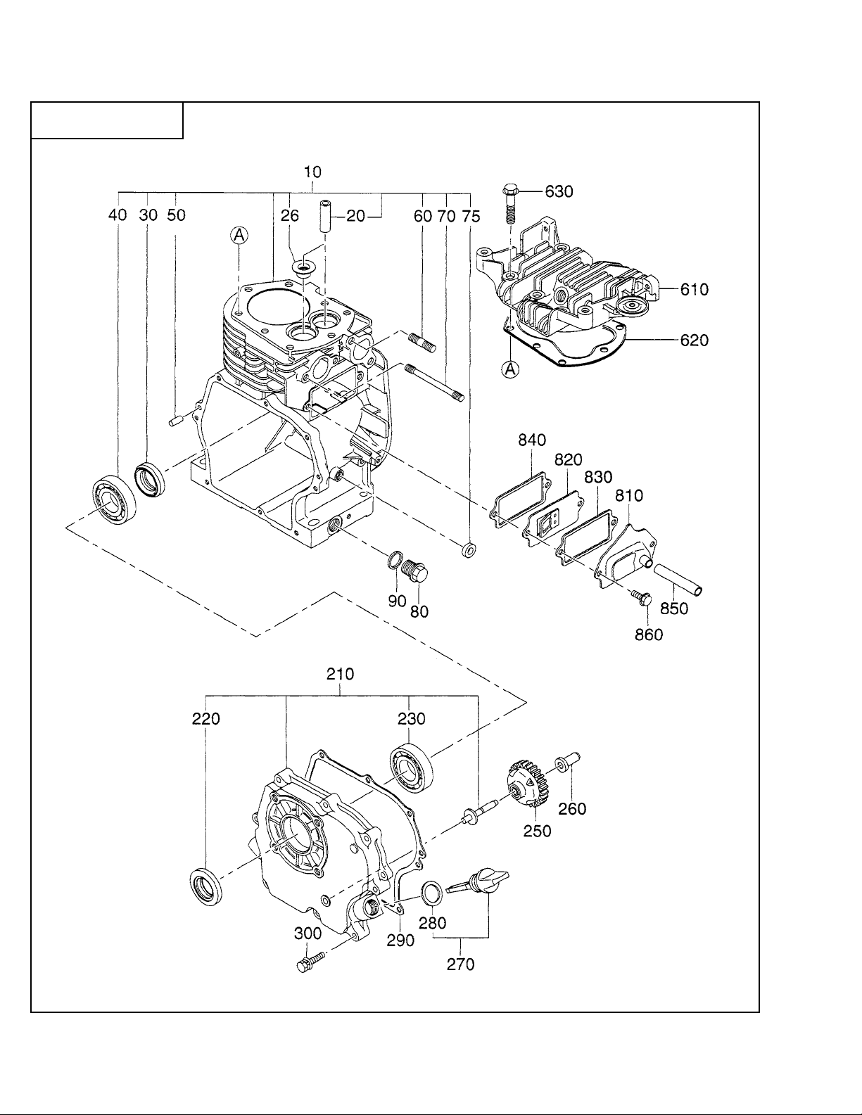
SECTION 1 CRANKCASE GROUP
FIG. 100
EY15-3 - 6 - 02-03
Page 7

SECTION 1 CRANKCASE GROUP
REF. PART NO. DESCRIPTION QTY. REMARKS FROM-TO FIG.
10 281-10111-01 CRANKCASE CP 1 w/ stem seal 100
20 227-14202-03 VALVE GUIDE 2 100
26 282-16301-03 STEM SEAL 1 100
30 044-02501-50 OIL SEAL 1 100
40 X60-02500-10 BALL BEARING 1 100
50 031-00600-20 DOWEL PIN 2 100
60 010-50802-50 STUD 2 100
70 010-50601-20 STUD 2 100
75 044-00800-10 OIL SEAL 1 VC8144 100
80 040-11400-30 PLUG 2 100
90 021-11400-20 GASKET 2 EY153YD1030 100
021-81400-10 GASKET 2 EY153YD4000 100
210 282-11002-01 MAIN BEARING COVER CP 1 100
220 044-02501-60 OIL SEAL 1 100
230 X60-02500-10 BALL BEARING 1 100
250 227-45003-01 GOVERNOR GEAR CP 1 100
260 205-41901-03 GOVERNOR SLEEVE 1 100
270 282-63601-H1 OIL GAUGE CP 2 100
280 X21-31600-20 GASKET 2 100
290 227-16001-03 GASKET, bearing cover 1 100
300 013-00600-40 BOLT and WASHER AY 8 100
610 226-13001-13 CYLINDER HEAD CP 1 100
620 281-15001-01 GASKET CP, head 1 100
630 011-00800-10 FLANGE BOLT 8 100
810 227-14301-01 TAPPET COVER CP 1 100
820 227-14401-01 BREATHER PLATE CP 1 100
830 282-16006-03 GASKET, tappet cover 1 100
840 282-16007-03 GASKET, breather plate 1 100
850 085-10800-00 RUBBER PIPE 1 100
860 011-00600-20 FLANGE BOLT 2 100
*960 281-99001-07 GASKET SET 1 100
* Gasket Set 281-99001-07 includes the following:
Fig 100 items 290, 620, 830 and 840
Fig 300 items 340, 550 and 560
EY15-3 - 7 - 02-03
Page 8

SECTION 2 CRANKSHAFT GROUP
FIG. 200
EY15-3 - 8 - 02-03
Page 9

SECTION 2 CRANKSHAFT GROUP
REF. PART NO. DESCRIPTION QTY. REMARKS FROM-TO FIG.
10 281-21002-01 CRANKSHAFT CP 1 EY153YD1030 200
281-20901-01 CRANKSHAFT CP 1 EY153YD4000 200
40 023-02501-10 SPACER 1 200
41 023-02501-20 SPACER 1 200
42 023-02501-30 SPACER 1 200
50 002-18140-00 NUT 1 200
60 003-20140-00 SPRING WASHER 1 200
70 032-30300-10 WOODRUFF KEY 1 200
310 226-22501-10 CONNECTING ROD AY 1 200
320 226-23001-13 CONNECTING ROD BOLT 2 200
330 226-23101-03 OIL SCRAPER 1 200
350 214-23301-13 PISTON PIN 1 200
360 226-23411-03 PISTON 1 STD 200
361 226-23412-03 PISTON 1 Oversize 0.25 200
362 226-23413-03 PISTON 1 Oversize 0.50 200
370 226-23511-07 PISTON RING SET 1 STD 200
371 226-23512-07 PISTON RING SET 1 Oversize 0.25 200
382 226-23513-07 PISTON RING SET 1 Oversize 0.50 200
380 056-51400-10 CLIP 2 200
EY15-3 - 9 - 02-03
Page 10

SECTION 3 INTAKE and EXHAUST GROUP
FIG. 300
A B
EY15-3 - 10 - 02-03
Page 11

SECTION 3 INTAKE and EXHAUST GROUP
REF. PART NO. DESCRIPTION QTY. REMARKS FROM-TO FIG.
10 226-31701-13 CAMSHAFT 1 300
50 226-33301-03 TAPPET 2 300
60 227-33601-03 VALVE SPRING 2 300
70 227-33701-03 SPRING RETAINER 2 300
80 281-33401-03 INTAKE VALVE 1 300
90 281-33501-03 EXHAUST VALVE 1 300
310 281-30101-H1 MUFFLER CP 1 300
320 281-34201-H1 MUFFLER COVER CP 1 300
340 281-35201-01 GASKET CP, ehaust 1 300
350 017-00800-30 NUT 2 300
360 011-00600-10 FLANGE BOLT 3 300
440 282-37001-H3 DEFLECTOR 1 300
445 015-00400-10 TAPPING SCREW 2 300
510 282-32610-00 AIR CLEANER AY 1 EY153YD1030 300A
226-32665-10 AIR CLEANER AY 1 EY153YD4000 300B
-2 282-32651-08 PACKING 1 EY153YD1030 300A
227-36003-13 PACKING 1 EY153YD4000 300B
-110 282-32640-08 COVER CP 1 EY153YD1030 300B
520 282-32601-07 ELEMENT SET 1 EY153YD1030 300A
226-32660-17 ELEMENT SET 1 EY153YD4000 300B
540 227-32901-13 INSULATOR 1 300
550 282-35901-03 GASKET, insulator 1 300
560 227-35904-03 GASKET 2, insulator 1 300
570 226-39212-00 NUT and WASHER AY 2 300
580 001-10061-20 BOLT and WASHER AY 1 300
EY15-3 - 11 - 02-03
Page 12

SECTION 4 GOVERNOR GROUP
FIG. 400
EY15-3 - 12 - 02-03
Page 13

SECTION 4 GOVERNOR GROUP
REF. PART NO. DESCRIPTION QTY. REMARKS FROM-TO FIG.
10 281-42301-01 GOVERNOR LEVER CP 1 EY153YD1030 400
281-42302-01 GOVERNOR LEVER CP 1 EY153YD4000 400
20 227-42201-03 GOVERNOR SHAFT 1 400
26 003-11080-00 WASHER 1 400
30 227-42701-01 GOVERNOR ROD 1 400
40 227-42801-03 ROD SPRING 1 400
50 003-13060-00 CLIP 2 400
60 001-14062-50 BOLT and WASHER AY 1 400
70 018-60600-20 NUT 1 400
80 226-42501-13 GOVERNOR SPRING 1 400
310 227-43301-10 SPEED CONTROL AY 1 EY153YD1030 400
227-43302-20 SPEED CONTROL AY 1 EY153YD4000 400
330 227-43601-03 KNOB 1 400
340 227-43501-13 STOP PLATE 1 400
350 227-45002-03 SPRING WASHER 1 400
360 004-31063-00 SCREW 1 400
370 002-27060-00 NUT 1 400
380 011-00600-30 FLANGE BOLT 1 EY153YD1030 400
011-00600-50 FLANGE BOLT 1 EY153YD4000 400
410 227-44203-13 WIRE BRACKET 1 400
440 004-31040-80 SCREW 1 400
450 002-27060-00 NUT 1 400
EY15-3 - 13 - 02-03
Page 14

SECTION 5 COOLING and STARTING GROUP
FIG. 500
EY15-3 - 14 - 02-03
Page 15

SECTION 5 COOLING and STARTING GROUP
REF. PART NO. DESCRIPTION QTY. REMARKS FROM-TO FIG.
10 281-51262-01 BLOWER HOUSING CP 1 EY153YD1030 500
281-51361-01 BLOWER HOUSING CP 1 EY153YD4000 500
20 281-95101-03 LABEL, model 1 500
21 073-20051-40 LABEL, trademark 1 500
40 011-00600-20 FLANGE BOLT 4 500
41 001-11062-00 BOLT and WASHER AY 1 500
60 226-52601-03 CYLINDER BAFFLE 1 500
80 011-00600-10 FLANGE BOLT 1 500
90 226-52701-03 HEAD COVER 1 500
220 011-00600-20 FLANGE BOLT 4 EY153YD1030 500
011-00600-10 FLANGE BOLT 4 EY153YD4000 500
EY15-3 - 15 - 02-03
Page 16

SECTION 5 COOLING and STARTING GROUP
FIG. 510
A
B
EY15-3 - 16 - 02-03
Page 17

SECTION 5 COOLING and STARTING GROUP
REF. PART NO. DESCRIPTION QTY. REMARKS FROM-TO FIG.
210 281-50311-00 RECOIL STARTER AY 1 EY153YD1030 510A
281-50211-00 RECOIL STARTER AY 1 EY153YD4000 510B
-1 226-50716-08 SPIRAL SPRING 1 EY153YD1030 510A
270-50115-08 SPIRAL SPRING 1 EY153YD4000 510B
-2 281-50320-08 REEL 1 EY153YD1030 510A
281-50120-08 REEL 1 EY153YD4000 510B
-3 281-50310-08 STARTER ROPE 1 EY153YD1030 510A
281-50111-08 STARTER ROPE 1 EY153YD4000 510B
-4 281-50300-08 STARTER KNOB 1 EY153YD1030 510A
261-50100-08 STARTER KNOB 1 EY153YD4000 510B
-5 281-50325-08 RATCHET 1 EY153YD1030 510A
270-50125-08 RATCHET 2 EY153YD4000 510B
-6 281-50330-08 FRICTION SPRING 1 EY153YD1030 510A
227-50131-08 FRICTION SPRING 1 EY153YD4000 510B
-8 281-50340-08 FRICTION PLATE 1 510A
-11 281-50345-08 STARTER PULLEY 1 EY153YD1030 510A
268-50145-18 STARTER PULLEY 1 EY153YD4000 510B
-35 270-50261-08 RATCHET GUIDE 1 510B
-49 281-50351-08 CENTER SCREW 1 EY153YD1030 510A
227-50152-08 CENTER SCREW 1 EY153YD4000 510B
EY15-3 - 17 - 02-03
Page 18

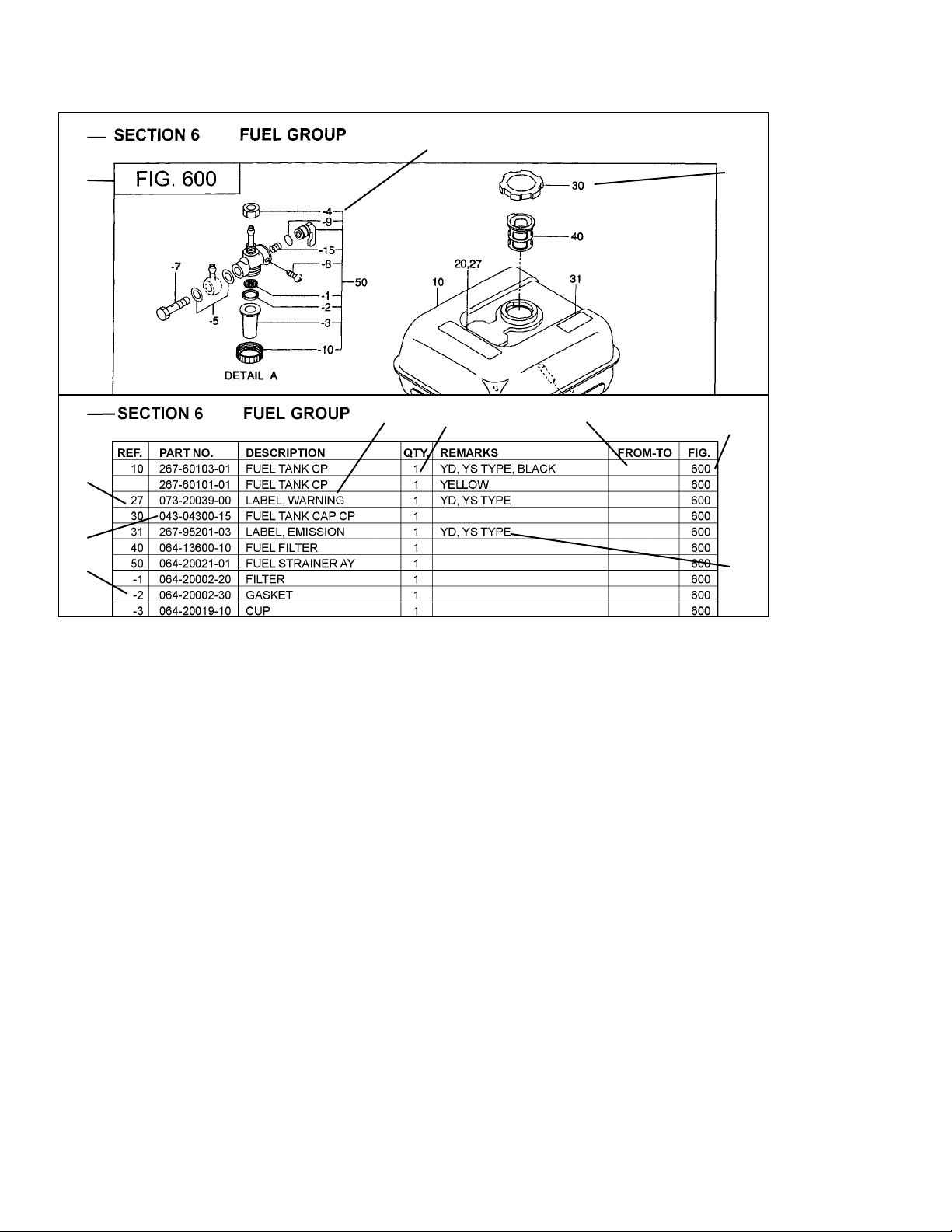
SECTION 6 FUEL, LUBRICANT GROUP
FIG. 600
50
EY15-3 - 18 - 02-03
Page 19

SECTION 6 FUEL, LUBRICANT GROUP
REF. PART NO. DESCRIPTION QTY. REMARKS FROM-TO FIG.
10 281-60111-01 FUEL TANK CP 1 Black 600
20 073-20039-00 LABEL, warning 1 600
30 043-04301-00 FUEL TANK CAP CP 1 EY153YD1030 600
043-04300-15 FUEL TANK CAP CP 1 EY153YD4000 600
40 064-13600-10 FUEL FILTER 1 600
50 064-20064-00 FUEL STRAINER AY 1 600
-1 064-20064-20 FILTER 1 600
-2 064-20064-10 PACKING 1 600
-3 064-20042-10 CUP, strainer 1 600
-4 064-20064-30 NUT 1 600
-6 064-20064-40 PACKING 1 600
60 002-38060-00 FLANGE NUT 2 600
70 281-62601H1 FUEL PIPE CP 1 600
80 281-62601-H3 RUBBER PIPE 1 600
90 X56-11100-20 HOSE CLAMP 2 600
220 226-66002-13 PIPE, air vent 1 600
EY15-3 - 19 - 02-03
Page 20

SECTION 6 FUEL, LUBRICATION GROUP
FIG. 610
EY15-3 - 20 - 02-03
Page 21

SECTION 6 FUEL, LUBRIACTION GROUP
REF. PART NO. DESCRIPTION QTY. REMARKS FROM-TO FIG.
210 226-62460-00 CARBURETOR AY 1 EY153YD1030 610
226-62455-00 CARBURETOR AY 1 EY153YD4000 610
-1 214-62535-08 THROTTLE VALVE 1 610
-2 209-62351-08 SCREW 1 610
-3 227-62527-08 CHOKE VALVE 1 610
-4 237-62451-08 SCREW 2 610
-5 246-62420-08 PILOT JET 1 #40 610
-8 226-62520-18 SHAFT AY, choke 1 610
-9 226-62551-08 RING 1 610
-11 226-62532-08 SHAFT AY, throttle 1 610
-12 227-62451-08 BOLT 1 610
-13 226-62550-08 RING 1 610
-14 26-62502-08 NEEDLE VALVE AY 1 610
-15 214-62515-08 PIN 1 610
-16 227-62558-08 FLOAT CHAMBER BODY 1 610
-17 214-62450-08 PACKING 1 610
-18 214-62540-08 CHAMBER PACKING 1 610
-19 226-62506-08 FLOAT AY 1 610
-20 226-62440-08 NOZZLE 1 EY153YD1030 610
226-62456-08 MAIN NOZZLE 1 EY153YD4000 610
-21 227-62441-08 NOZZLE 1 610
-22 253-62401-08 MAIN JET 1 EY153YD1030 610
226-62411-08 MAIN JET 1 EY153YD4000 610
-24 226-62701-18 CLIP 1 610
-30 209-62446-08 CHOKE SPRING 1 610
-31 209-62353-08 STEEL BALL 1 610
-32 106-62392-08 SEAL 1 610
-40 209-62352-08 SCREW 1 610
-41 209-62445-08 SPRING 1 610
-60 156-62351-08 PACKING 1 610
-62 227-62559-08 SEAL 1 610
EY15-3 - 21 - 02-03
Page 22

SECTION 7 ELECTRIC DEVICE GROUP
FIG. 700
EY15-3 - 22 - 02-03
Page 23

SECTION 7 ELECTRIC DEVICE GROUP
REF. PART NO. DESCRIPTION QTY. REMARKS FROM-TO FIG.
10 281-79201-01 FLYWHEEL CP 1 700
11 281-79401-01 IGNITION COIL CP 1 700
30 011-00601-21 FLANGE BOLT 2 700
60 X66-00003-61 SWITCH AY 1 700
70 015-00400-90 TAPPING SCREW 2 700
100 065-01401-50 SPARK PLUG 1 NGK-BR6HS 700
RL86C SPARK PLUG 1 CHAMPION 700
110 065-50000-51 SPARK PLUG CAP 1 700
EY15-3 - 23 - 02-03
Page 24

SECTION 8 OIL SENSOR GROUP GROUP
FIG. 800
EY15-3 - 24 - 02-03
Page 25

SECTION 8 OIL SENSOR GROUP GROUP
REF. PART NO. DESCRIPTION QTY. REMARKS FROM-TO FIG.
700 KS3-11020-01 OIL SENSOR CP 11 1 EY153YD4000 800
760 214-73122-01 WIRE 22 CP 1 EY153YD4000 800
772 214-79003-01 CLAMP CP 1 EY153YD4000 800
774 206-75501-01 CLAMP CP 1 EY153YD4000 800
775 001-10081-60 BOLT and WASHER AY 1 EY153YD4000 800
776 011-00600-10 FLANGE BOLT 1 EY153YD4000 800
EY15-3 - 25 - 02-03
Page 26

PRINTED IN THE USA
 Loading...