

Page 1
Page 2
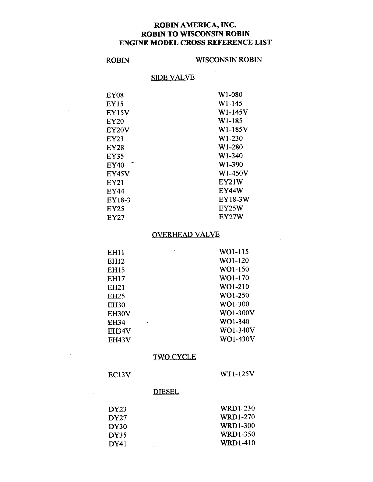
ROBIN
AMERICA, INC.
ROBIN
TO
WISCONSIN
ROBIN
ENGINE
MODEL
CROSS REFERENCE
LIST
ROBIN
EY08
EY15
EY 15V
EY20
EY2OV
EY23
EY28
EY3
5
EY40
-
EY45V
EY2
1
EY44
EY 18-3
EY25
EY27
EH11
EH12
EH15
EH17
EH21
EH25
EH30
EH30V
EH34
EH34V
EH43V
EC13V
DY23
DY27
DY30
DY3
5
DY4 1
WISCONSIN
ROBIN
SIDE
VALVE
W
1-080
W1-145
W1-145V
W1-185
W1-185V
W1-230
W 1-280
W
1-340
W 1-390
Wl-45OV
EY21W
EY44W
EY18-3W
EY25W
EY27W
OVERHEAD
VALVE
WO1-115
wo1-120
WO1-150
WO1-170
wo1-210
WOl-250
WO 1-300
WO1-300V
WO1-340
WO
1
-340V
WO 1-43 OV
TWO CYCLE
WT1-125V
DIESEL
WRD
1-230
WRD
1-270
-1-300
WRD1-350
WRD1-410
0
0
0
Page 3
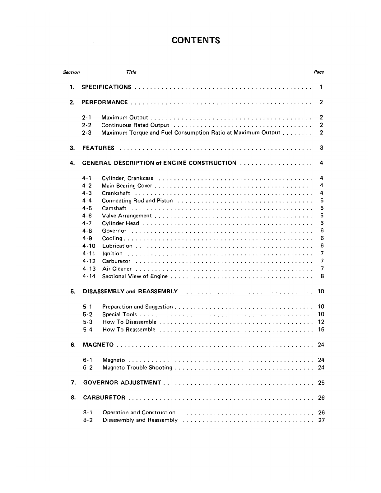
CONTENTS
Section
Title
Page
1
.
SPECIFICATIONS
..............................................
1
2
.
PERFORMANCE
...............................................
2
2-1
Maximum Output
..........................................
2
2-2
Continuous Rated Output
....................................
2
2-3
Maximum Torque and Fuel Consumption Ratio
at
Maximum Output
........
2
3
.
FEATURES
..................................................
3
4
.
GENERAL DESCRIPTION
of
ENGINE CONSTRUCTION
...................
4
4-1
4-2
4-3
4-4
4-5
4-6
4-7
4-8
4-9
4-10
4-1 1
4-12
4-13
4-14
Cylinder. Crankcase
........................................
4
Main Bearing Cover
.........................................
4
Crankshaft
..............................................
4
Connecting Rod and Piston
...................................
5
Camshaft
...............................................
5
Valve Arrangement
.........................................
5
Cylinder Head
............................................
6
Governor
...............................................
6
Cooling
.................................................
6
Lubrication
..............................................
6
Ignition
................................................
7
Carburetor
..............................................
7
Air Cleaner
..............................................
7
Sectional View
of
Engine
.....................................
8
5
.
DISASSEMBLY
and
REASSEMBLY
..................................
10
5-
1
Preparation and Suggestion
....................................
10
5-2
Special Tools
.............................................
10
5-3
How
To
Disassemble
........................................
12
5-4
How
To
Reassemble
........................................
16
6
.
MAGNETO
...................................................
24
6-1
Magneto
................................................
24
6-2
Magneto Trouble Shooting
....................................
24
7
.
GOVERNOR ADJUSTMENT
.......................................
25
8
.
CARBURETOR
................................................
26
8-1
Operation and Construction
...................................
26
8-2 Disassembly and Reassembly
..................................
27
Page 4
Section
Title
Page
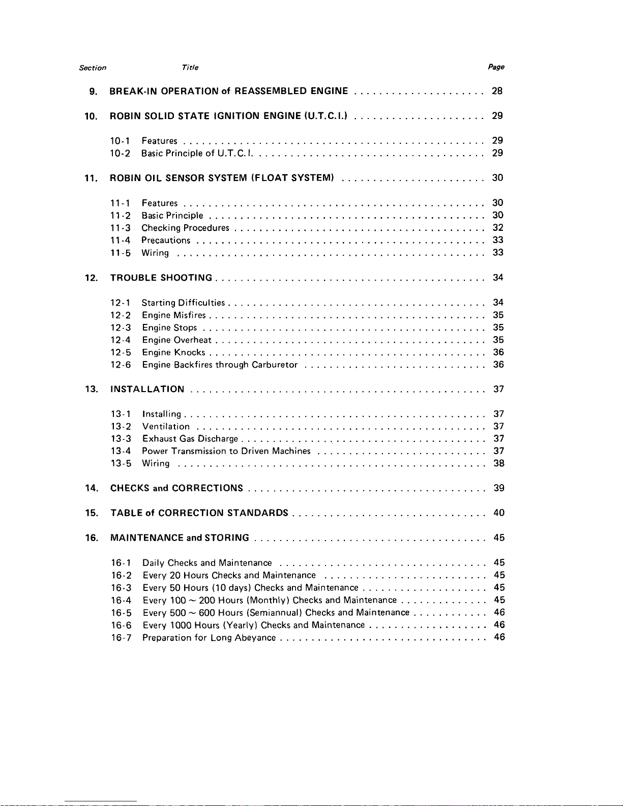
9
.
BREAK-IN OPERATION
Of
REASSEMBLED ENGINE
.....................
28
10
.
ROBIN SOLID STATE IGNITION ENGINE (U.T.C.I.)
.....................
29
10-1
Features
................................................
29
10-2
Basic Principle of U.T.C.
I
.....................................
29
I1
.
ROBIN OIL SENSOR SYSTEM (FLOAT
SYSTEM)
.......................
30
11-1
Features
................................................
30
11
-2
Basic Principle
............................................
30
11
-3
Checking Procedures
........................................
32
11
-4
Precautions
..............................................
33
11-5
Wiring
.................................................
33
12
.
TROUBLE SHOOTING
...........................................
34
12-
1
Starting Difficulties
.........................................
34
12-2
Engine Misfires
............................................
35
12-4
Engine Overheat
...........................................
35
12-3
Enginestops
.............................................
35
12-5 Engine Knocks
............................................
36
12-6
Engine Backfires through Carburetor
.............................
36
13
.
INSTALLATION
...............................................
37
13-1
Installing
................................................
37
13-2
Ventilation
..............................................
37
13-3
Exhaust Gas Discharge
.......................................
37
13-4
Power Transmission to Driven Machines
...........................
37
13-5
Wiring
.................................................
38
14
.
CHECKS
and
CORRECTIONS
......................................
39
15
.
TABLE
of
CORRECTION STANDARDS
...............................
40
16
.
MAINTENANCE
and
STORING
.....................................
45
16-1
Daily Checks and Maintenance
.................................
45
16-2
Every
20
Hours Checks and Maintenance
..........................
45
16-3
Every
50
Hours
(IO
days)
Checks and Maintenance
....................
45
16-4
Every
100
.
200
Hours (Monthly) Checks and Maintenance
..............
45
16-5
Every
500
.
600
Hours (Semiannual) Checks and Maintenance
............
46
16-6
Every
1000
Hours (Yearly) Checks and Maintenance
...................
46
16-7
Preparation for Long Abeyance
.................................
46
Page 5
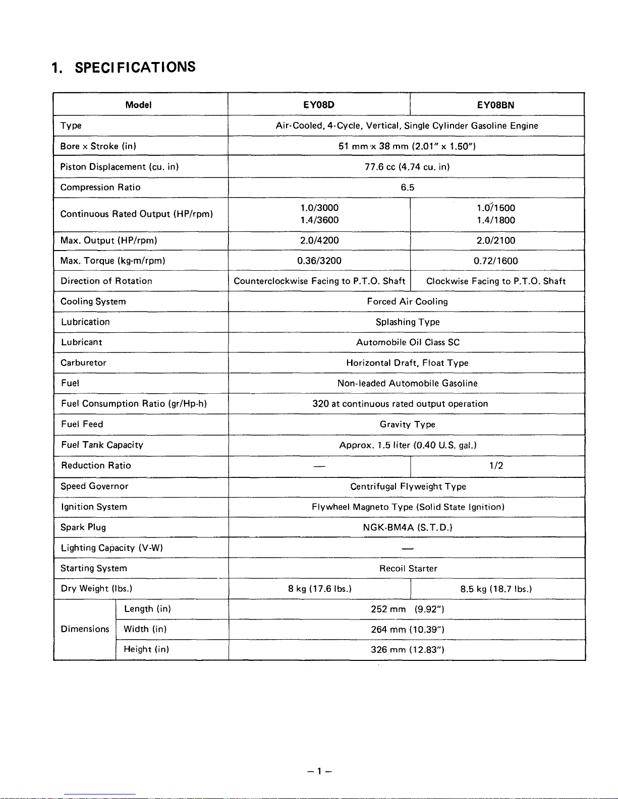
1.
SPEC1
FICATIOMS
Model
EY08BN EY08D
Air-Cooled, 4-Cycle, Vertical, Single Cylinder Gasoline Engine
Bore x Stroke (in)
77.6 cc (4.74 cu. in) Piston Displacement (cu. in)
51
mm
'x
38
mm
(2.01"
x
1.50")
Compression Ratio
6.5
Continuous Rated Output (HP/rpm)
1.0/3000
1.4/3600
1
.O?
1 500
1.4/1800
Max. Output (HP/rpm)
0.72/1600 0.36/3200
Max. Torque (kg-m/rpm)
2.0/2
1
00
2.0/4200
Direction of Rotation
1
Counterclockwise Facing to P.T.O. Shaft
Clockwise Facing to P.T.O. Shaft
Cooling System
I
Forced Air Cooling
~
Lubrication
Splashing Type
Lubricant
Automobile Oil Class
SC
~~
Carburetor
Horizontal Draft, Float Type
~~
Fuel
320
at
continuous rated output operation Fuel Consumption Ratio (gr/Hp-h)
Non-leaded Automobile Gasoline
Fuel Feed
I
Gravity Type
Fuel
Tank
Capacity
I
Approx.
1.5
liter (0.40
U.S.
gal.)
Reduction Ratio
I
-
1
/2
Speed Governor
8.5 kg (18.7 Ibs.)
8 kg (17.6 Ibs.)
Dry Weight (Ibs.)
Recoil Starter
Starting System
-
Lighting Capacity (V-W)
NGK-BM4A (S.T.D.)
Spark Plug
Flywheel Magneto Type (Solid
State
Ignition) Ignition System
Centrifugal Flyweight Type
Length (in)
326
mm
(12.83")
Height
(in)
264
mm
(10.39")
Width (in)
Dimensions
252 mrn (9.92")
-1
-
Page 6
2.
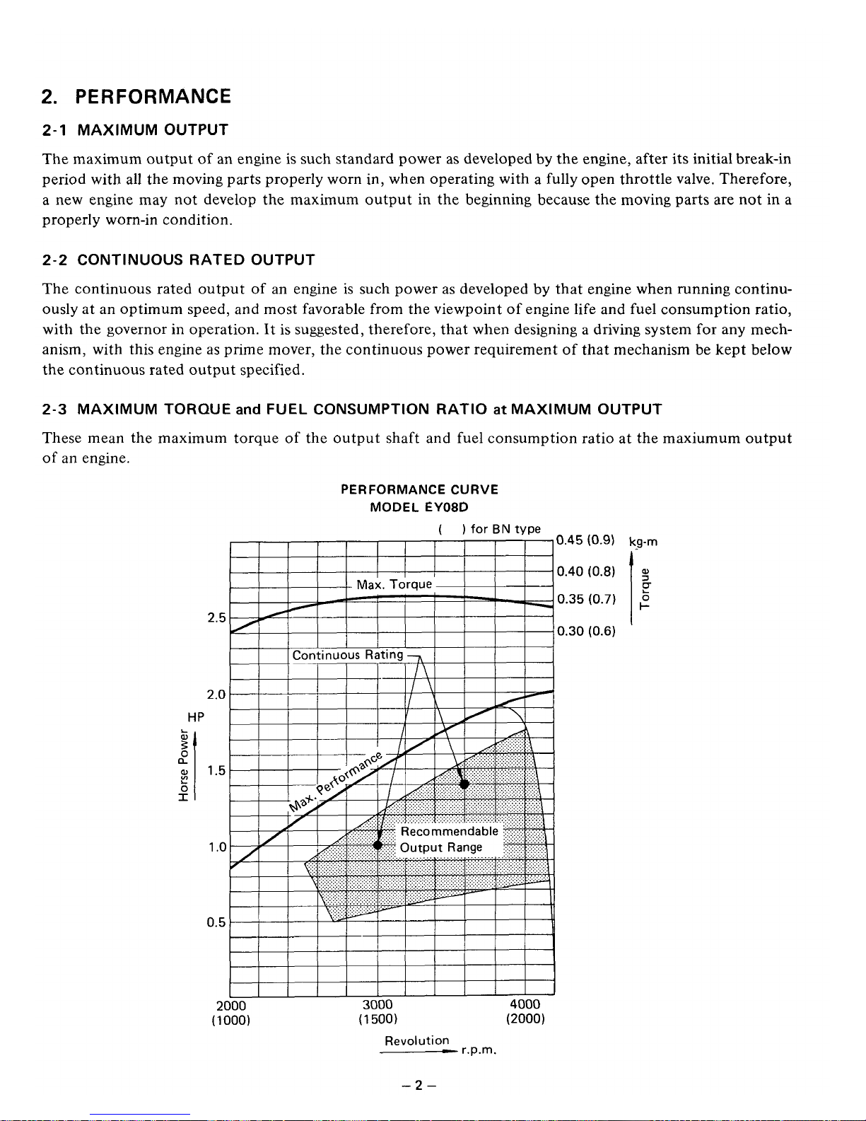
PERFORMANCE
2-1
MAXIMUM OUTPUT
The maximum output of an engine
is
such standard power as developed by the engine, after its initial break-in
period with all the moving parts properly worn in, when operating with a fully open throttle valve, Therefore,
a new engine may not develop the maximum output in the beginning because the moving parts are not in a
properly worn-in condition.
2-2
CONTINUOUS RATED OUTPUT
The continuous rated output of an engine
is
such power as developed
by
that engine when running continuously at an optimum speed, and most favorable from the viewpoint of engine life and fuel consumption ratio,
with the governor in operation. It is suggested, therefore, that when designing a driving system
for
any mech-
anism, with this engine
as
prime mover, the continuous power requirement
of
that mechanism be kept below
the continuous rated output specified.
2-3
MAXIMUM TORQUE
and
FUEL CONSUMPTION
RATIO
at
MAXIMUM OUTPUT
These mean the maximum torque of the output shaft and fuel consumption ratio at the maxiumum output
of
an
engine.
HP
L
W
0
a
3’
L
0
I
PERFORMANCE
CURVE
MODEL
EY08D
( )
for
BN
type
0.45
0.40
0.35
0.30
2.5
2.0
1.5
1
.o
0.5
2000
3000
4000
(1
000)
(1
500)
(2000)
Revolution
-
r.p.m.
(0.9)
kg-rn
-2-
Page 7

3.
FEATURES
1.
Compact, lightweight, durable, powerful 4cycle air cooled engine embodying ingenious design techniques
and skilful workmanship.
2.
Simple construction, smart appearance, maximum easiness
of
start owing to automatic decompression
device
3.
Pointless Solid State ignition system is newldy adopted for preventing poor igniting.
4.
Reliable prime mover for varietyof purposes with smooth speed controlrby a governor under varying load
conditions.
5.
Economical because fuel consumption is very low
-3-
Page 8
4.
GENERAL DESCRIPTION
of
ENGINE CONSTRUCTION
4-1
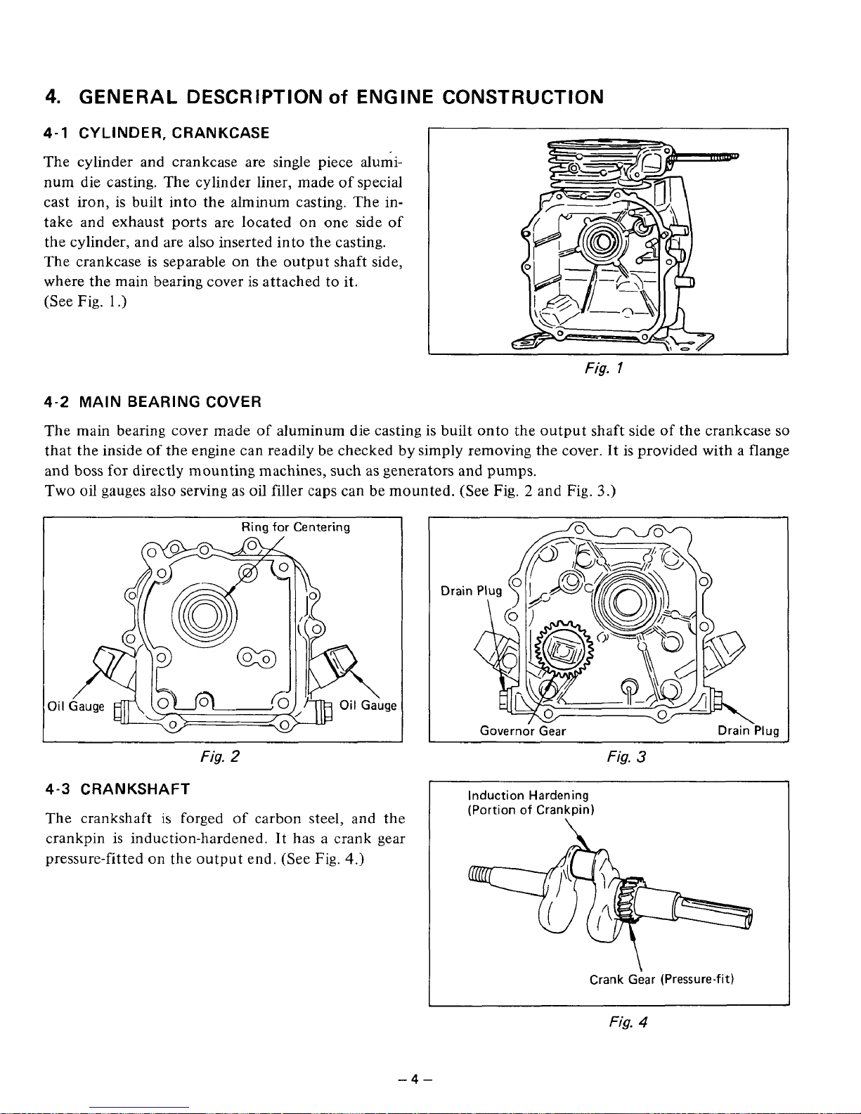
CYLINDER, CRANKCASE
The cylinder and crankcase are single piece aluminum die casting. The cylinder liner, made of special
cast iron, is built into the alminum casting. The
in-
take and exhaust ports are located on one side
of
the cylinder, and are also inserted into the casting.
The crankcase is separable on the output shaft side,
where the main bearing cover
is
attached to it.
(See Fig.
1
.)
Fig.
1
4-2
MAIN
BEARING
COVER
The main bearing cover made
of
aluminum die casting is built onto the output shaft side
of
the crankcase
so
that the inside of the engine can readily be checked by simply removing the cover. It is provided with a flange
and boss for directly mounting machines,
such
as
generators and pumps.
Two oil gauges also serving
as
oil filler caps can be mounted. (See
Fig.
2
and
Fig.
3.)
Oi
I
Ring
for Centering
!ID
Oil
Gauge
Fig.
2
4-3
CRANKSHAFT
The crankshaft is forged of carbon steel, and the
crankpin
is
induction-hardened. It has a crank gear
pressure-fitted on the output end. (See
Fig.
4.)
Fig.
3
~~
Induction Hardening
(Portion of Crankpin)
\
Crank Gear (Pressure-fit)
Fig.
4
-4-
Page 9
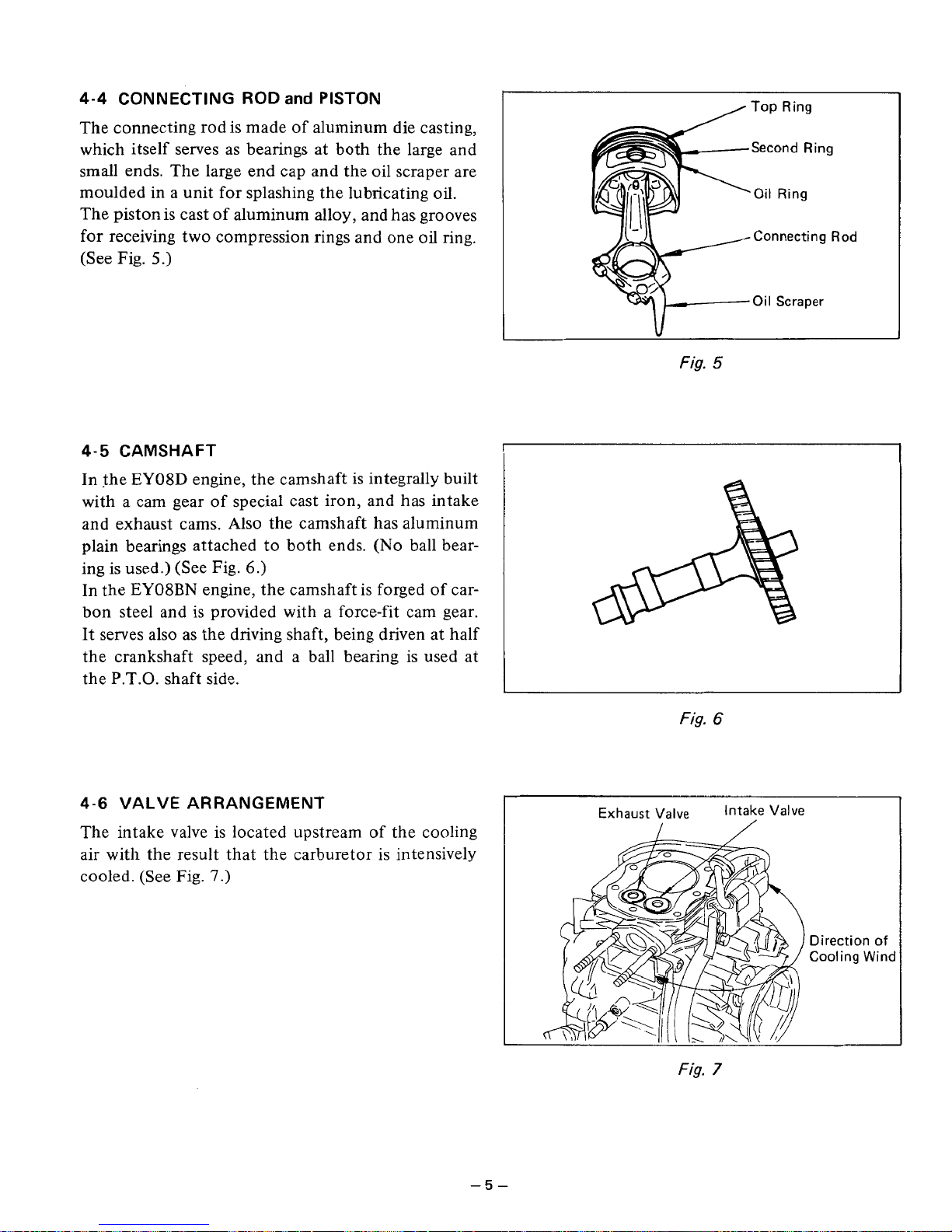
The connecting rod is made of aluminum die casting,
which itself serves as bearings at both the large and
small ends. The large end cap and the oil scraper are
moulded in a unit for splashing the lubricating oil.
The piston is cast
of
aluminum alloy, and has grooves
for receiving two compression rings and one
oil
ring.
(See Fig.
5.)
4-4
CONNECTING ROD
and
PISTON
4-5 CAMSHAFT
In the EY08D engine, the camshaft is integrally built
with a cam gear of special cast iron, and has intake
and exhaust cams. Also the camshaft has aluminum
plain bearings attached to both ends.
(No
ball bear-
ing is used.) (See Fig.
6.)
In the EY08BN engine, the camshaft is forged of carbon steel and is provided with a force-fit cam gear.
It serves also
as
the driving shaft, being driven at half
the crankshaft speed, and a ball bearing is used at
the P.T.O. shaft side.
4-6
VALVE ARRANGEMENT
The intake valve is located upstream
of
the cooling
air with the result that the carburetor is intensively
cooled. (See Fig.
7.)
Top
Ring
Second Ring
Oil
Ring
Connecting
Rod
Oil
Scraper
\I
L
Fig.
5
:
Fig.
6
Direction
of
Cooling
Wind
Fig.
7
-5-
Page 10
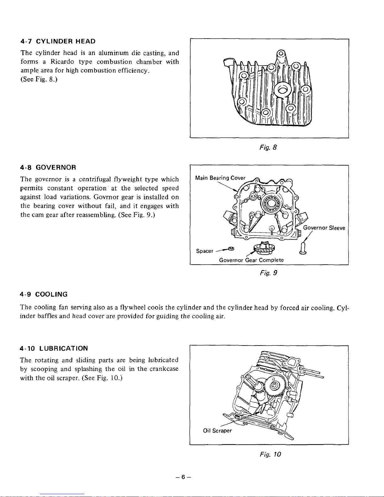
4-7
CYLINDER HEAD
The cylinder head
is
an aluminum die casting, and
forms a Ricardo type combustion chamber with
ample area for high combustion efficiency.
(See
Fig.
8.)
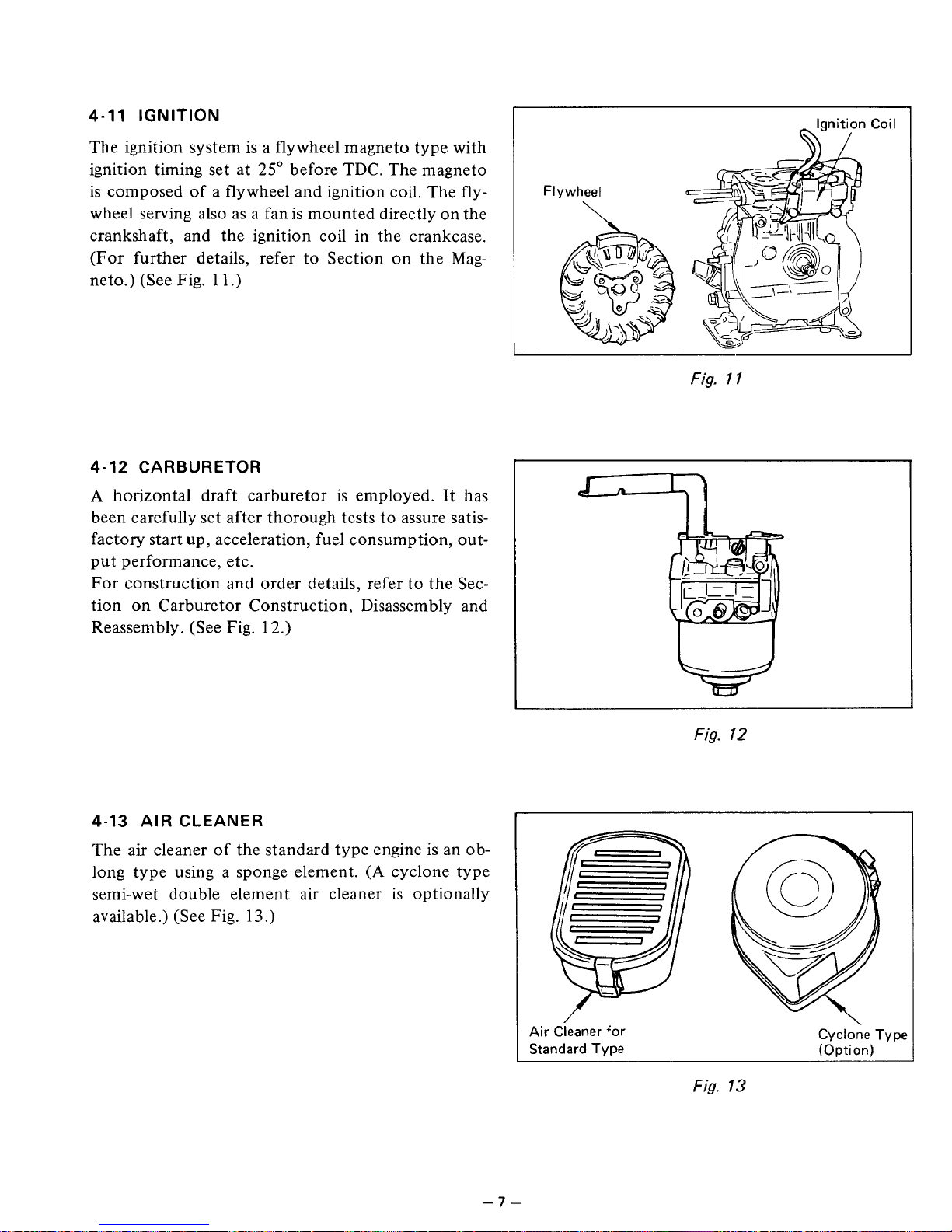
4-8
GOVERNOR
The governor is a centrifugal flyweight type which
permits constant operation- at the selected speed
against load variations. Govrnor gear is installed on
the bearing cover without fail, and
it
engages with
the cam gear after reassembling. (See Fig.
9.)
I
Fig.
8
Main
Be
!mor
Sleeve
Spacer
Q
-
Governor Gear Complete
Fig.
9
4-9
COOLING
The cooling fan serving also as a flywheel cools the cylinder and the cylinder head by forced air cooling. Cylinder baffles
and
head cover are provided for guiding the cooling air.
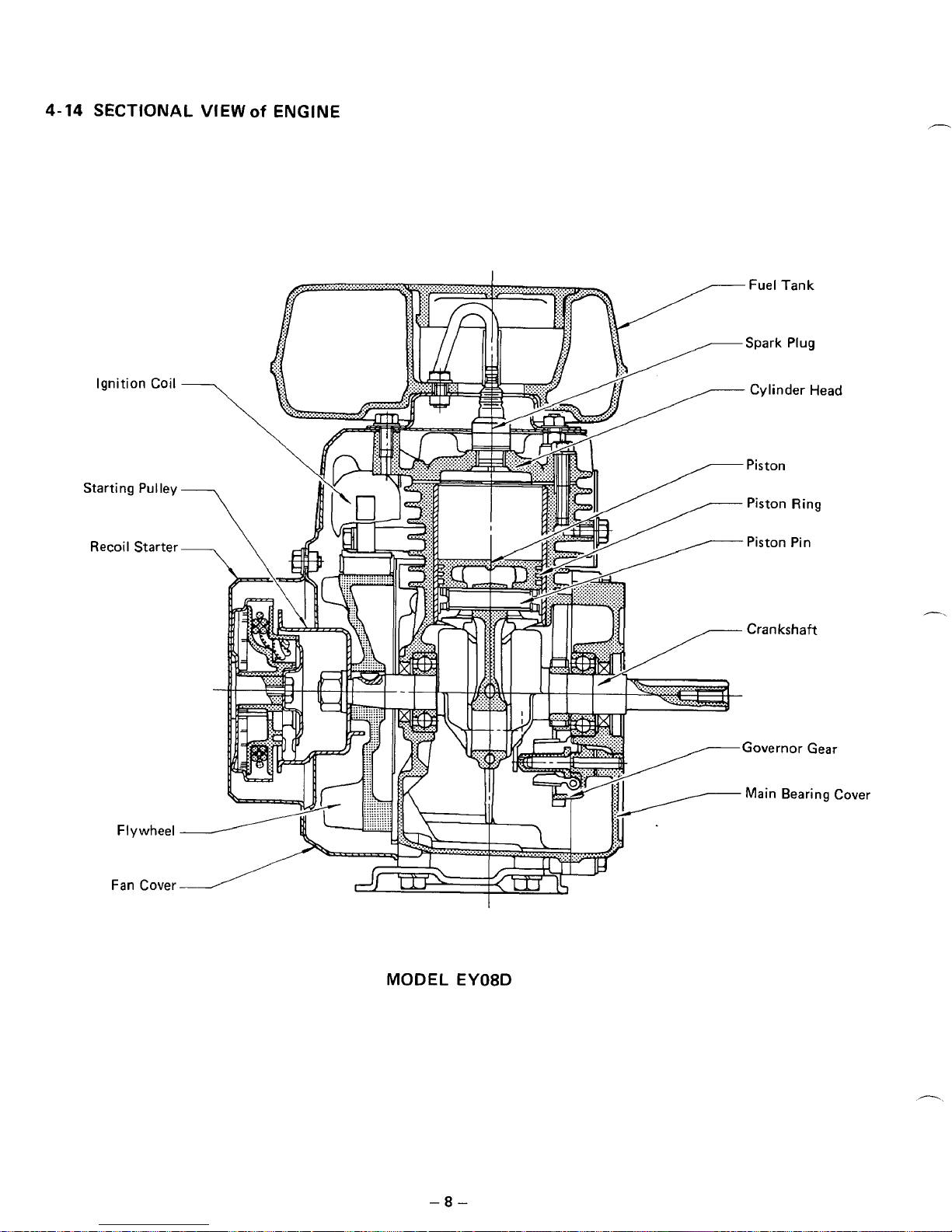
4-10
LUBRICATION
The rotating and
sliding
parts are being lubricated
by scooping
and
splashing the
oil
in the crankcase
with the
oil
scraper. (See Fig.
10.)
Fig.
10
-6-
Page 11
4-11
IGNITION
The ignition system
is
a flywheel magneto type with
ignition timing set at
25"
before TDC. The magneto
is composed
of
a
flywheel and ignition coil. The fly-
wheel serving also as a fan is mounted directly on the
crankshaft, and the ignition coil in the crankcase.
(For further details, refer to Section
on
the Mag-
neto.) (See
Fig.
1 1
.)
4-12 CARBURETOR
A
horizontal draft carburetor is employed. It has
been carefully set after thorough tests to assure satisfactory start up, acceleration, fuel consumption, output performance, etc.
For construction and order details, refer to the Section on Carburetor Construction, Disassembly and
Reassembly. (See Fig. 12.)
4-13 AIR CLEANER
The air cleaner
of
the standard
ty
:ngine
is
an
0
b-
long type using a sponge element.
(A
cyclone type
semi-wet double element air cleaner is optionally
available.) (See
Fig.
13.)
I
Ignition Coil
Fig.
1
1
Fig.
12
Air Cieaner for
Standard Type
Cyclone Type
(Option)
Fig.
13
-7-
Page 12
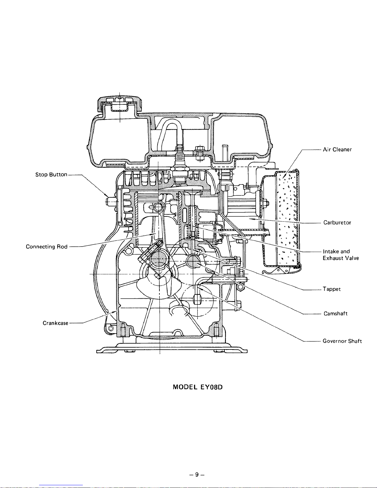
4-14
SECTIONAL
VIEW
of
ENGINE
MODEL
-8-
EY08D
Page 13
Stop Button
Connecting
Rod
Crankcase
MODEL
EY08D
Air
Cleaner
Carburetor
Intake and
Exhaust Valve
Tappet
Camshaft
Governor
Shaft
-9-
Page 14
5.
DISASSEMBLY
and
REASSEMBLY
5-1
PREPARATIONS
and
SUGGESTIONS
1)
When disassembling the engine, remember well the locations of individual parts
so
that they can be reas-
sembed correctly.
If
you are uncertain
of
identifying some parts, it
is
suggested that tags be attached
to
them.
2)
Have boxes ready
to
keep disassembed parts by group.
3)
To
prevent missing and misplacing, temporarily assemble each group of disassembed parts.
4)
Carefully handle disassembed parts, and clean them with washing oil.
5)
Use the correct tools
in
the correct way.
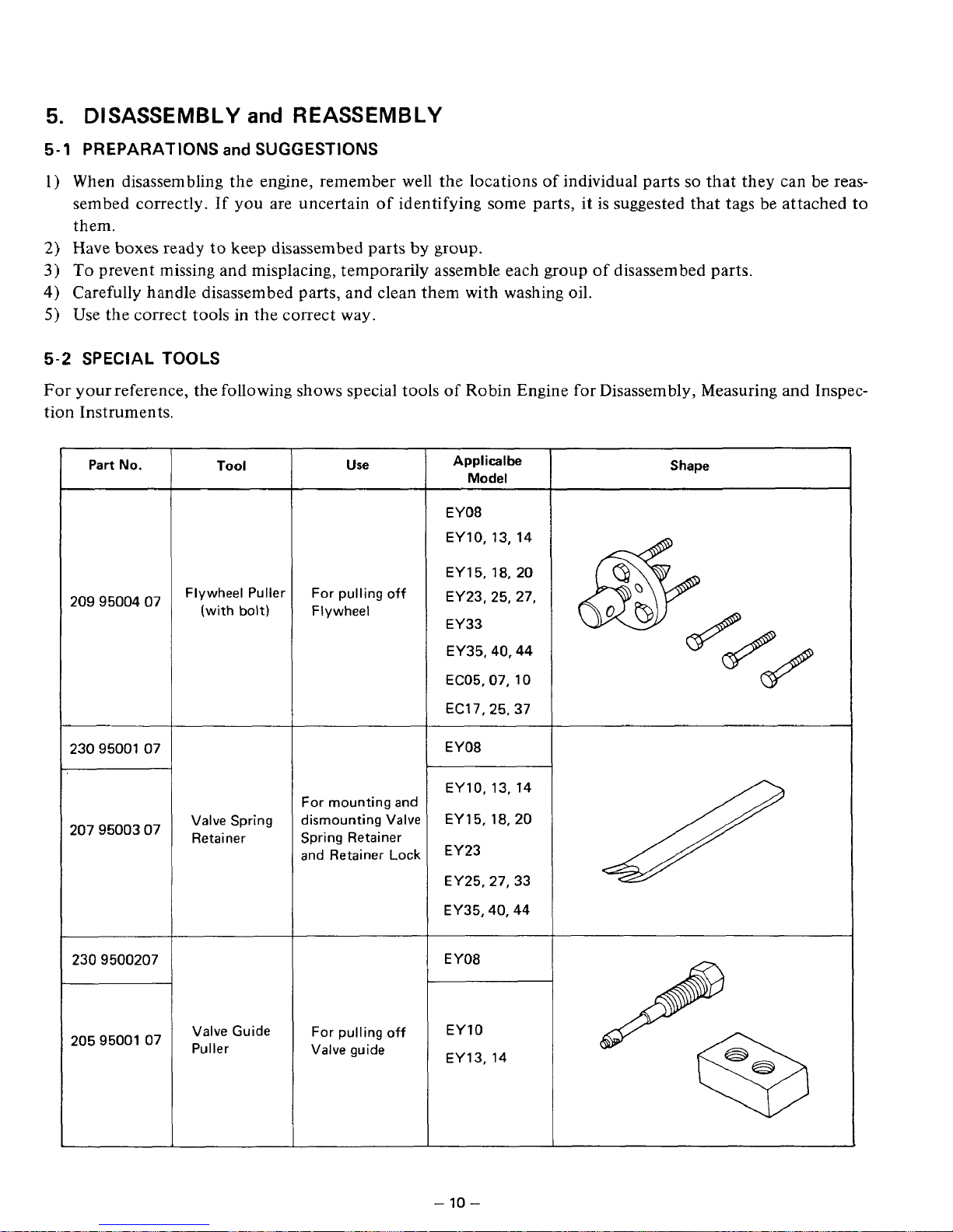
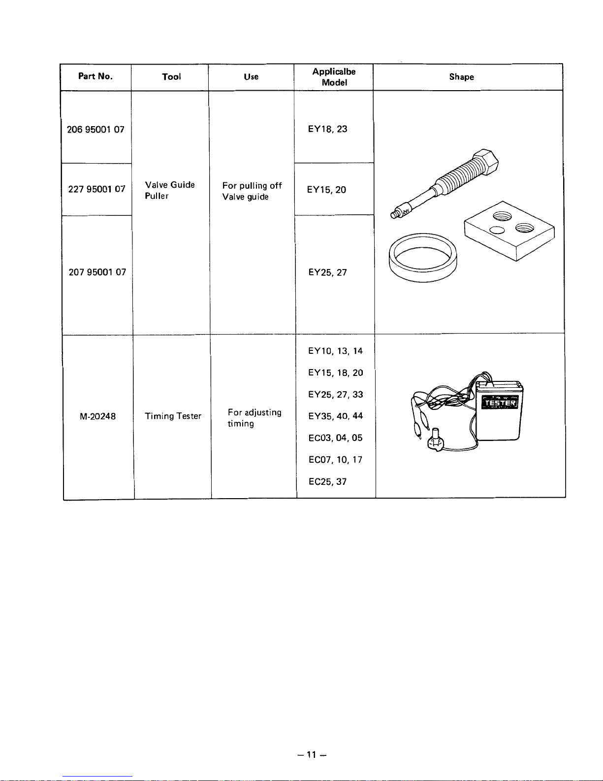
5-2
SPECIAL
TOOLS
For
your reference, the following shows special tools of Robin Engine for Disassembly, Measuring and Inspec-
tion Instruments.
Part
No.
2099500407
2309500107
2079500307
2309500207
2059500107
Tool
Flywheel Puller
(with
bolt)
Valve Spring
Retainer
Valve Guide
Puller
Use
For pulling
off
Flywheel
For mounting and
dismounting Valve
Spring Retainer
and Retainer
Lock
For pulling off
Valve guide
Applicalbe
Model
EY08
EY10, 13, 14
EY
15,18,
20
EY23, 25, 27,
EY33
EY35,40,44
EC05.07, 10
EC17,25.37
EY08
EY10,13, 14
EY 15, 18,20
EY23
EY25.27, 33
EY35,40,44
EY08
EY10
EY13,
14
Shape
-10-
Page 15
Part
No.
2069500107
2279500107
207 95001 07
“20248
Tool
Valve Guide
Puller
Timing Tester
Use
For pulling
off
Valve guide
For
adjusting
timing
Applicalbe
Model
EY18.23
EY 15,ZO
EY25, 27
EY10,
13,
14
EY 15, 18,20
EY25,27,33
EY35,40,44
EC03,04,05
EC07,10,
17
EC25,37
Shape
-
11
-
Page 16
5-3
HOW
TO
DISASSEMBLE
*Length of the bolt indicates the length from the bolt head bottom surface to the threaded end.
Order
5
I
tern
Fuel tank
Recoil starter
Tank bracket
Head cover
Fan cover
Muffler cover
Muffler
Air cleaner
Procedures
(1)
Close the fuel cock.
(2)
Disconnect the fuel pipe between the fuel
strainer and carburetor at the carburetor
side.
(3) Remove the fuel tank from the tank bracket.
M6
x
14
mm bolt
:
3
pcs.
(1)
Remove the recoil starter.
M6
x
8
mm bolt
:
3
pcs.
(1)
Remove the
tank
bracket, the head cover,
and the fan cover from the crankcase and
the cylinder head.
M6
x
10
rnm
bolt
:
2
pcs.
M6
x
12
bolt
:
1
pce.
M6 nut
:
2
pcs.
(1)
Remove the muffler cover 1 from the
muffler.
M6
x
8
mm bolt
:
2
pcs.
(2)
Remove the muffler from the cylinder
portion
of
the crankcase.
M6
x
28
mrn bolt
:
1
pce.
M6
x
50 mm bolt
:
1
pce.
(1)
Remove the air cleaner cover and the
(2)
Remove the
air
cleaner case from the
element.
carburetor.
M6 nut
:
2
pcs.
(3) Disconnect the breather pipe.
Remarks
Sems bolt
Fastened together
Remove the primary
wire of the stop button.
Air cleaner is fastened together with the
carburetor.
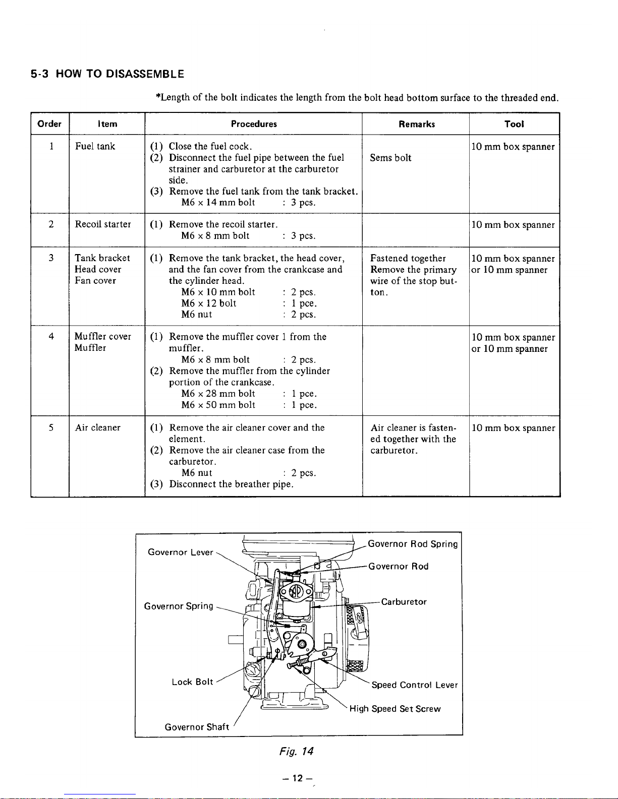
Governor Lever
Governor Spring
Lock
Bolt
{--)
,Governor Rod Spring
Governor
Rod
Lever
L
'
High
Speed Set
Screw
Governor
Shaft
Fig.
14
Tool
10
mm box spanner
IO
mm box spanner
10
m
box spanner
Ir
10
mm spanner
10
mm box spanner
x
10
mm
spanner
10
mm box spanner
-
12
-
Page 17

Order
Itern Procedures
I
Remarks
I
Too
I
6
Governor lever
and the relative
parts
Carburetor
Starting pulley
Flywheel
(1)
Remove the governor Iever from the gover-
M6
x
25 mm bolt
:
1
pce.
nor shaft.
(2) Remove the governor rod and rod spring
(3) Remove the carburetor from the
from the carburetor.
cylinder portion
of
the crankcase.
Just loosen the bolt,
unnecessary to take
out the bolt.
10
mm box spanner
or
10
mm spanner
(1) Remove the starting pulley from the
fly-
Be
careful not to
wheel.
damage the blades
of
M12 nut
:
1
pce.
the flywheel with
a
Fit a box
or
socket wrench over the fly-
wheel nut, and strike it hard with a ham-
driver and a like.
wise with a hammer.
mer to remove the nut and spring washer.
Strlke counterclock(See Fig.
15)
17
mm box spanner
or
socket wrench
(1)
Remove the flywheel from the crankshaft.
Fit the flywheel
puller as shown
in
Fig.
16,
turn the
center bolt clockwise and pull out
the flywheel.
Fig.
15
Fig.
16
Order
I
tern
Procedures
~ ~~~~~~~~~~~ ~ ~~
9
(1)
Remove the plug terminal from the spark
Ignition coil
plug and remove the ignition coil from the
crankcase.
M6
x
25
mm
bolt
:
2
pcs.
10
(1)
Remove the spark plug from the cylinder
Spark plug
he ad
Remarks
Sems bolt
7
10
mm
box
spanner
I
19 mm box spanner
-
13
-
Page 18

Order
I
Item
11 Cylinder head
I
l2
I
Intake and
exhaust valve
13
I
Main bearing
cover
Procedures
(1)
Remove the
M6
bolts and remove the cylin-
M6
x
32
mm bolt
:
5
pcs.
M6
x
40
mm bolt
:
2
pcs.
(2)
Remove the cylinder head gasket from the
der head from the crankcase
crankcase.
(1)
Remove the inner and outer tappet covers
M6
x
12
mm bolt
:
2
pcs.
from the crankcase.
(2)
Pull out the intake and exhaust valve.
(3)
Remove the valve spring and the valve
spring retainer.
(1) From the crankcase remove the bolt fasten-
M6
x
25
mm bolt
:
6 pcs.
(2)
Remove the cover, lightly tapping the cover
ing the main bearing cover.
evenly with a plastic hammer.
\
(-)
Driver
\
Fig.
17
Remarks
M6
x
40
mm bolt
is
special bolt.
Put the notch on the
outer circumference
of the spring retainer
on this side.
Hook the medium
size
(-)
driver at the
dent (lower side)
of
the spring retainer
and pull out the
valves, while pulling
the spring retainer
toward you.
(See Fig.
17.)
Sems bolt
Be careful not to
damage the oil seal.
(See Fig.
18.)
Tool
10
mm
box
spanner
The front is this
sidf
(-)
driver
10 mm
box
spanner
Main/Bearing Cover
I
Plastic Hammer
Fig.
18
-
14
-
Page 19

Procedures
I
Remarks
I
Too
I
(1)
Remove the camshaft from the crankcase. To prevent the tap-
pets from falling or
damaging, place the
crankcase
on
the
side. (See Fig.
19
.)
15
Tappet
~~~ ~~~~ ~~~ ~~
I
(1) Remove the tappets from the crankcase.
Before removing put
a mark of intake or
exhaust
on
each
tappet.
Order
16
17
18
I
tern
Connecting rod
and piston
Piston and
piston pin
Crankshaft
Camshaft
Procedures
(1)
Scrape off carbon and other foreign deposits
from the upper parts of the cylinder and
piston, and then straighten out the bent
tabs of the lock washers
on
the connect-
ing rod, and remove two pieces of the bolt.
(2)
Remove the lock washer and the connecting
rod cap from the crankshaft.
(3)
Turn the crankshaft until the piston is raised
up to the hghest position, push the connecting rod
up,
and
remove the piston out of the
top
of
the cylinder.
(1) Remove the two clips, pull out the piston
pin, and take the piston off from the small
end of the connecting rod.
(2)
Spread the open ends of the piston rings
and remove them from the piston.
(1)
Remove the woodruff key (for the magneto).
(2)
Lightly hammer the magneto end of the
crankshaft, and pull it out of the crankcase.
-
15
-
Remarks
I
Tool
8
mm
box
spanner
or
8
mm spanner
Pay attention to the
direction
of
the con-
necting rod cap.
Be careful
not
to
damage the inside of
the small end of the
connecting rod.
Be careful not to
break the rings by
spreading too much.
Be careful not to
damage the oil seal.
Page 20

5-4
HOW
TO
REASSEMBLE
.Precaution in reassembling
Every and each part should be cleaned thoroughly. Especially, pay utmost care and attention to the cleanliness of the piston, cylinder, crankshaft, connecting rod and bearings.
Scrape completely off carbons from the cylinder head and the upper part of the piston; especially the
carbon adhered in the groove of the piston ring should be carefully and completely taken out.
Carefully check the lip portion of every
oil
seal. If faulty one is found, replace it without any hesitation.
Apply enough oil
to
the lip portion of the oil seal when reassembling.
Replace all the gaskets with new ones.
Replace the key, pin, bolt, nuts, etc. with new one, if necessary.
Whenever tightening torque
is
specified, conform to the specified figures.
Apply oil to the revolutionary parts and friction surfaces, when reassembling.
Check and adjust the clearances of various portions and then reassemble.
When some main portions are assembled in the course of reassembling, turn
or
move the gadgets by hand
and pay attention to the frictional noise and resistance.
*Sequence and precautions in reassembling
5-4-1 GOVERNOR
SHAFT
1)
Insert the governor shaft into the crankcase.
2)
Place the clips
on
the governor shaft.
5-4-2 CRANKSHAFT
1) Inser the crankshaft into the crankcase as shown
.
Note: Be careful not to damage
the
oil
seal
lip.
in Fig.
20.
2)
Put woodruff key (for magneto) in place.
Shaft
Fig.
20
-16-
Page 21

3)
Dimensions
of
Crankshaft
Pin
D
(Crankshaft Pin Dia.)
20
dia.
-0.037
-
0.050
W
(Crankshaft Pin Width)
PISTON TO CYLINDER AT PISTON SKIRT
THRUST FACE
I
PISTON RING
GAP
tx"--+
TOP, SECOND
0.008L
-
0.047L
0.2
L - 0.4L
0.05L
-
0.25L (Cutter Ring)
PISTON RING CLEARANCE
IN
GROOVES
i
TOP RING
SECOND RING
OIL RING
CONNECTING ROD TO CRANK PIN
DIA
0.09OL -0.135L
0.060L
-
0.105L
0.01OL
-
0.065L (Cutter
Ring)
0.037L - 0.063L
0.1
L - 0.7L
CONNECTING ROD TO PISTON PIN
PISTON PIN TO PISTON
0.010L
-
0.029L
0.009T
-
0.01OL
L:
LOOSE
Fig.
21
-
17-
T:
TIGHT
Page 22

5-4-3
PISTON and
PISTON
RING
1) If
no
ring expander is available, install the rings by placing the open ring ends over
the
first land of the
piston and spreading the rings only far enough to slip them over the correct ring grooves.
Note:
Pay
attention not to break the rings by twisting. Install the oil ring first followed by the second
ring and then top ring. Meantime, the surfaces of the second ring and the top ring with carved
carved marks are to be faced up.
Note: When replacing the piston rings with new ones, install the rings
for
replacement
as
shown in Fig.
22.
n
I
@
STD
I
Replacement Parts
I
Top Ring Taper
I
I
Taper
Second Ring
Taper
Undercut
Ql
Oil
Ring
Cutter Ring
Assembly type
a
Fig.
22
2)
Reassemble the piston and the connecting rod by
means of the piston pin.
Note: Apply enough oil to the
small
top end of
the connecting rod.
Be sure to place the clips on both ends of
the piston pin.
3)
When installing the connecting rod into place,
hold piston rings with the ring guide
as
shown in
Fig.
24
(if
no ring guide
is
available, keep pressing the piston rings with finger tips and gently
strike the top
of
the piston with a wooden piece
or the like
to
push
it
in), and check that the sym-
bol
@
or mark
MA
on the connecting rod
is
i
the direction
of
the flywheel magneto.
Note: Apply enough oil
to
the piston rings, con-
necting rod plain bearings and cylinder
wall before reassembling.
Note: The open ends of the piston rings must be
90"
apart from one another on the piston
periphery.
Note: The clearance between the piston and cyl-
inder must be measured
at
the piston skirt
thrust surface.
Fig.
23
Crank Case
(Magneto Side)
Fig,
24
-
18
-
Page 23

5-4-4
CONNECTING
ROD
1)
Turn the crankshaft to the bottom dead center,
lightly hammer the piston head until the connecting rod contacts the crankpin, and assemble.
2)
When reassembling the connecting
rod
cap, set it
so
that the
oil
scraper
is
in the right.bottom.
(See Fig.
25.)
Note: Use new lock washers, and bend the tabs
Note: After reassembly, confirm that the
con-
Note: Connecting rod cap tightening torque:
Note:
For
the piston,
piston
ring
and-
rod
clear-
securely,
necting rod moves lightly.
60
-
80
kg-cm
ance,
see
Fig.
2
1.
5-4-5
TAPPET and CAMSHAFT
Insert the tappets back into their holes first, and
then mount the camshaft.
Note: Align the timing mark at the root
of
a
tooth
of
the cam gear with the one
on
the crank
gear.
If
the valve timing
is
wrong, the engine
cannot operate properly
or
at
all.
(See Fig.
26.
)
Note:
If
the intake tappet and exhaust tappet were
assembled contrarily each other, the tappet
clearance cannot
be
kept correctly.
Fig.
25
Fig.
26
-
19
-
Page 24

5-4-6
Install the main bearing cover
Note:
Note: When installing main bearing cover, apply oil
Note: In the
MAIN BEARING COVER
to
the.crankcase.
As
the'governor gear
bearing cover side, install the main bearing
cover while checking that
teeth
of
the cam gear. (See Fig. 27.) Meantime,
if
the oil seal need be replaced, pressure-fit a
new oil seal before installing the main bearing
cover.
to the bearing and oil seal
guide over the crankshaft
tect the oil seal lip from damage. Then place
the main bearing cover
Check the crankshaft
0 - 0.2
justing shim. (See Fig. 28,)
the cam shaft with the adjust shim
from
mm; and if not, adjust
BN
type, adjust the side clearance of
0
to
0.2
mm.
is
mounted on the main
it
meshes with the
lip.
Fit the oil seal
or
camshaft to
on.
if
its
side clearance
it
with the ad-
so
that
pro-
it
is
is
-1
Pay attention to the engagement of
the governor ear and cam gear.
It
Fig.
27
Note: Main bearing cover tightening torque:
80
-
100
kg-cm
29
Note: Fig.
the crankshaft side clearance between the
machined face
collar.
chined face of the crankcase, adjust the clearance
account. (See Fig.
shows one of the methods measuring
of
the crankcase and adjusting
As
a paper packing
by
taking this thickness of0.22
29.)
is
used
on
the ma-
mm
into
1
(*-*
Fig.
28
Dial Indicator
Ground Surface
(The surface
to be put together with the surface of the main bearing cover.)
Fig.
29
of
of
the crankcase
is
-
20
-
Page 25

5
-4-7
INTAKE
and
EXHAUST
VALVES
Remove carbon and gum deposite
from
the valves, valve seats, intake and exhaust
ports
and valve guides,
Note:
If
the valve face
is
dinted
or
warped, replace the valves with new ones.
Note:
If
there
is
an excessive clearance between the valve guide and valve stem, replace the valve guide with a
spare.
For
replacing,
pull
out the valve guide, using the valve guide pulling base and
bolts
as shown
in
Fig.
30,
and pressure-fit a new valve guide into place.
Valve
Face
%
Spring Retainer
Fig.
30
VALVE
and
VALVE
GUIDE
CLEARANCE
I
A-VALVE FACE ANGLE
I
4
5"
I
I
B-
SEAT
ANGLE
I
45"
I
C-GUIDE INSIDE DIA.
5.5
dia.
+0.018
0
I
MAXIMUM ALLOWABLE
0.056L
-
0.092
L
EXHAUST
CLEARANCE BETWEEN C and
D
0.020L
-
0.050L
INTAKE
L:
LOOSE
Fig.
31
-
27
-
Page 26

5-4-8
TAPPET ADJUSTMENT
Lower the tappet all the way down, push the valve, and insert a thickness gauge between the valve and tap-
Fig.
pet stem to measure the clearance. (See
Note: The correct tappet clearance for both intake and exhaust valves
when the engine
is
cold.
32.)
is
0.1
mm
k0.02
mm as measured
-
Note:
Fig.
If
the clearance
On the contrary,
I
Thickness Gauge
32
is
smaller than specified, slightly grind the top of the valve stem, and measure
if
the clearance
is
too large, replace the valve with new one, and polish
Valve
Valve Spring
Valve Spring Retainer
fig.
33
it
its
again.
contact
surface with a compound to obtain a good fit. Then adjust the clearance.
Note: After the tappet clearance adjustment, install the valve springs and the valve spring retainers, and turn
the crankshaft, and measure the tappet clearance once again if
it
is
correct.
n
Note: INSTAL
Place the notch
the retainer toward this side and insert the retainer, like pushing in, using a special tool.
a driver
5-4-9
CYLINDER HEAD
LA
TION of SPRING RETAINERS
on
the outer circumference of
is
used, insertion may be easier.
Front
should
be
this
side.
lf
\-I
Driver
‘\
Fig.
34
Valve
Spl
l
Retainer
kg
Remove carbon from the cylinder head, particularly its combustion chamber, and make clean the cooling
Also
fins.
check the head for distortion.
Note: Replace the cylinder head gasket with a new one.
Note: Cylinder head tightening torque:
90
-
110
kg-cm
/”-.
-
22
-
Page 27

5-4-10 SPARK PLUG
Tightening torque of the spark plug: 230
-
250
kg-cm.
Note:
If
the spark plug
is
new, tighten the spark plug at
120
-
150
kg-cm torque.
5-4- 11 IGNITION COIL, FLYWHEEL and STARTER PULLEY
1)
Temporarily fasten the ignition coil to the crankcase, and install the flywheel to the crankshaft. Starting
pulley is fastened together with the flywheel.
Note: Before installing, wipe out oil from the crankshaft and the tapered portion
of
the flywheel.
Note: Before installing the starting pulley, check
if
the woodruff key
is
correctly inserted.
Note: Flywheel tightening torque:
450 - 500
kg-cm.
2) After measuring the air gap between the ignition
coil and flywheel, retighten the ignition coil.
(See Fig.
35.)
Air gap:
0.3
-
0.5
mm
I
Fig.
35
5
-4- 12 CARBURETOR
To the cylinder portion of the crankcase install in the order of the gasket, insulator, gasket and carburetor,
and then mount the air cleaner case and fasten with two pieces
of
M6 nut.
5
-4-
13
GOVERNOR LEVER
When reassemblying, refer to the
7.
GOVERNOR
ADJUSTMENT.
5-4-14 MUFFLER and MUFFLER COVER
Install the muffler cover
2
to the muffler and fasten the muffler
to
the crankcase and then install the muf-
fler cover 1.
Note: Muffler tightening torque:
100
-
720
kg-cm
Note: Clamp the muffler and tighten the bolts after the engine has been fully cooled.
5-4-15
HEAD COVER, FUEL TANK, FUEL TANK BRACKET and FAN COVER
Install in the order
of
the head cover, fan cover, fuel tank bracket and fuel tank.
Note: Install the grommet of the ignition coil to the head cover before installing the fan cover.
5-4- 16 RECOIL STARTER
With 3 pieces of M6
x
8
mm
bolt fasten the recoild starter.
Note:
It
is
feared that the bolt longer than 8 mm may damage
the
blade.
-
23
-
Page 28

6.
MAGNETO
6-1
MAGNETO
/-
The spark for ignition is furnished by the magneto assembly. The magneto consists
of
the flywheel and the
ignition coil of which flywheel is mounted on crankshaft and ignition coil is mounted in crankcase directly.
6-2
MAGNETO TROUBLE SHOOTING
When the engine does not start or starts with difficulty, or when its operation is unstable, the following tests
in
will clarify if they are caused by a defect
1)
Check ignition cable for possible corrosion, broken, worm insulator or lose connection.
2)
Check the sparking as described later in this section.
3)
If no spark takes place, replace ignition coil.
*SPARK
TESTING
the magneto.
Remove the spark plug from the cylinder head and place it on the cylinder head, with the ignition cable
connected to it.
Crank the engine several times
the spark
is
strong, the ignition system can be eliminated as the source
by
recoil starter and observe the spark
in
the spark gap
of
trouble. (Remove the primary
of
spark plug.
If
wire from the connector.)
is
If the spark
The
correct electrode gap
weak or there
is
no spark at all, repeat the checks.
is
0.6
-
0.7
mm. (Refer to section
“14.
CHECKS and CORRECTIONS.”)
Flywheel
Fig.
I
36
/“
-
24
-
Page 29

7.
GOVERNOR
ADJUSTMENT
Model
EY08
emploies a centrifugal flyweight type governor. The governor is mounted on the govenor gear
nor in order
to
maintain constant engine speed against load variations.
The adjustment procedure
of
the governor is as follows (See Figs.
37 - 39.):
1)
Connect the carburetor throttle lever
to
the governor lever with the governor rod and the rod spring and
2)
Install the speed control lever
to
the crankcase.
3)
Connect the governor lever
to
the control lever with the governor spring.
and the throttle valve
of
the carburetor
is
automatically regulated by a lever which is connected to the gover-
mount the governor lever onto the governor shaft.
Governor Lever
Governor
Rod
Governor
Spring
Governor
Shaft
Fig.
37
4)
Turn the control lever towards high speed, and
confirm that the carburetor throttle valve is fully
opened. Control lever can stay wherever it is
required.
*Position
to
hang the
governor
spring
The standard position
is
2-A.
But, in case of a
50Hz
generator, the governor should be hung at
3-B .
5)
With a screwdriver in the groove
of
the governor
shaft, turn it “clockwise” fully until the governor shaft no longer moves, and then look the
governor lever to the governor shaft with the
governor lever tightening bolt. (See Fig.
39.)
An example
of
the governor spring being hooked.
Fig.
38
Governor Lever
Fig.
39
-
25
-
Page 30

8.
CARBURETOR
/-
8-1
OPERATION
and
CONSTRUCTION
(See
Fig.
40.)
8-
1
-
1
FLOAT
SYSTEM
The float chamber
is
located just below the carburetor body and, with a float and a needle valve, maintains
a constant fuel level during engine operation.
The fuel flows from the fuel tank into the float chamber through the needle valve. When the fuel rises to a
specific level, the float rises; and when
its
buoyancy and fuel pressure are balanced, the needle valve close
to
the shut off the fuel, thereby keeping the fuel at the reference level.
Pilot Jet, ,,"--Pilot Air Jet
r
Pilot
Jet
Main Air Jet
/-
Needle Valve
Float
-
fig.
40
-
26
-
Page 31

8-1
-2
PILOT
SYSTEM
The pilot system feeds the fuel to the engine during idling and low-speed operation.
The fuel
is
fed through the main jet
to
the pilot jet, where it is metered, and mixed with the air metered by
the pilot air jet.
The fuel-air mixture is fed .to the engine through the pilot outlet and the by-pass.
During engine idling, the fuel is mainly fed from the pilot outlet.
8-
1-3
MAIN SYSTEM
The main system feeds the fuel to the engine during medium- and high-speed operation.
The fuel is metered by the main jet and fed to the main nozzle. The air metered by the main air jet is mixed
with the fuel through the bleed holes in the main nozzle, and the mixture is atomized out
of
the main bore.
It is mixed again with the air taken through the air cleaner into an optimum fuel-air mixture, which is
supplied
to
the engine.
8-
1
-4
CHOKE
The choke is used for easy start in the cold season. When the recoil starter
is
pulled with a closed choke, the
negative pressure applied
to
the main nozzle increases and draws much fuel accordingly; thus easily start up
the engine.
8-2 DISASSEMBLY
and
REASSEMBLY
Apart from mechanical failures, most of carburetor troubles are caused by an incorrect mixing ratio, which
may arise mainly due to a clogged up air or fuel passage in jets, or fuel level variations. In order to assure
proper flow
of
air and fuel, the carburetor must be kept clean at all times. The carburetor disassembly and
reassembly procedures are as follows: (See Fig.
41
.)
18
8-2-
1
THROTTLE
SYSTEM
1)
Remove the Philips screw (1
8)
and throttle valve
2)
The spirng
(21)
can be taken out by removing
*Exercise care not to damage throttle valve ends.
(19), and pull out the throttle shaft
(20).
the throttle stop screw (22).
8-2-2
CHOKE
SYSTEM
1)
Remove the Philips screw
(14)
and
choke valve
(1
S),
and pull out the choke shaft
(1
6).
2)
When reassembling the choke shaft, make sure
that the cutout in the choke valve faces the main
air jet.
8-2-3
PILOT
SYSTEM
Remove the pilot jet (23) using correct tool to
avoid damage to it.
Reassembly
Tighten the pilot jet securely. Otherwise, the fuel
may leak, causing engine malfunction.
17
7
12
A
Fig.
4
1
-
27
-
Page 32

8-2-4
MAIN
SYSTEM
1) Remove the bolt (12) and take out float chamber body
(10).
2)
Remove the main jet (1
3)
from the body
(6).
3)
Reassembly
a) Fasten the main jet securely to the body. Otherwise the fuel may become too rich and cause engine
b) The bolt tightening torque
is
70
kg-cm.
malfunction.
8-2-5
FLOAT
SYSTEM
Pull out the float pin
(9)
and remove the
float
(8)
and needle valve
(1
7).
If
the
needle valve need be re-
placed, replace it with rubber needle.
Caution: When cleaning the jets, use neither a drill nor a wire (because of possible damage of the orifice
which will adversely affect fuel flow). Be sure to use compressed air
to
blow them clean.
When removing the needle valve and floats, gently tap the reverse side using the rod more slender than
the float pin and remove because the float pin is calked to the carburetor body.
BREAK-IN OPERATION
of
REASSEMBLED ENGINE
An overhauled engine must be operated at low speed break-in the parts. A thorough break-in is indispensable
particularly when the cylinder, piston, piston rings or
valves
are replaced with new ones.
The recommended break-in schedule
is
shown below.
/-
I
LOAD
SPEED
(Crankshafr
Rev.)
TIME
I
2,500
rpm
10
minutes
NO
LOAD
3,000
rpm
10
minutes
NO
LOAD
30
minutes
3,600
rpm
0.7
PS
10
minutes
3,600
rpm
1.4
PS
60
minutes
3,600
rpm
-
28
-
Page 33

10.
ROBIN
SOLID
STATE IGNITION ENGINE'
(U.T.C.I.)
10-1
FEATURES
EY08 emploies a pointless ignition system, called Solid State Ignition, which is the circuit breaker type ignition device, utilizing the power transistor as an element for controling electric current.
This
ignition system is
called U.T.C.I. (Universal Type Transistor Controlled Ignition), and it is based on an external coil system
in which an ignition coil is installed outside the flywheel and the unit is mounted on an
iron
core of the coil.
Being different from the breaker point type ignition system, this brand-new system is completely free from
such troubles as starting-up failure owing to dirty, burnt or oxidized point surface, lowering
of
ignition effi-
ciency being caused by moisture, rough surface to breaker point and incorrect timing resultant from worn
mechanical parts.
10-2
BASIC PRINCIPLE
OF
U.T.C.!.
(See
Fig.
42.)
Electricity is generated
in
the primary ignition coil by rotation of the flywheel, and the current a flows,
by which the condenser is charged.
When the flywheel goes round further, direction
of
the current changes, and the current b flows, causing
the current
c
and the current d flow to the power transistor and the transistor for signals for each. The
condenser8is charged by the current
d
contrarily to the case
1).
When the flywheel goes round further more, the current generated in the primary coil gets to its peak,
and then begins decreasing.
Then, voltage between
C
(Collector) and E (Emitter) of the transistor for signals becomes zero, and the
transistor is turned
OFF,
while the current
d
changes to the current
e
and goes into the gate of the
thyrister
(SCR),
thus turning the
SCR
ON.
When the SCR is switched
ON
and the current
b
flows into the
SCR
(Current
f),
the current c flowing
the power transistor is interrupted abraptly, generating high voltage by the current change in the secondary coil, thus giving sparks to the spark plug.
ignition
Coil
Fig.
42
-
29
-
Page 34

1.1.
ROBIN
OIL
SENSOR
SYSTEM
(FLOAT
SYSTEM)
/-
In the
EYOS,
an oil sensor is available as a maker option.
11 - 1
FEATURES
1) The engine oil sensor detects the quantity of engine oil and automatically stops the engine, if
it
falls
below the specified level, to prevent the engine from burning due to oil maintenance failure
or
for other
reasons.
If the
oil
shortage warning lamp is connected to the connecting terminal for it. the warning lamp is lit
when the engine stops.
2)
If the engine oilis short when the engine is started, the engine can not be started, even
if
the recoil starter
is pulled. If the warning lamp is connected, the lamp is lit to indicate oil shortage.
3)
As
the power generated by the igniter
is
used, any special power supply unit is not necessary.
4)
On-tatch stop is possible also by using the stop button, which is generally incorporated in the unit, based
on a push button system. (Self-maintaining and automatic restoration circuits are incorporated in the
unit.)
5)
This system features the malfunction preventing structure depending on outer magnetic field.
11
-2
BASIC
PRINCIPLE
This oil sensor system consists of a flywheeI magneto, an igniter, an oil level controller, and an oil level
sensor.
As
shown in Fig.
43,
when the oil level is above the specified one, the lead switch contact
is
OFF,
and the
engine can run normally (sensor OFF condition). If the oil becomes short and position
of
the float in the
/"
sensor case goes down to the specified level shown in Fig.
44,
the lead switch contact
is
turned
ON
by the
magnetic field of the permanent magnet incorporated in the float (sensor
ON
condition).
When the oil level sensor is turned
ON,
the current
il
generated by the counter-electromotive voltage
VI
in
the primary ignition coil flows from the primary wire of the igniter via the delaying circuit of the oil level
controller, both
of
which are shown in the block diagram. When the current
iI
generated by the counter
electromotive voltage
VI
goes
up
to a certain level, the current
il
is loaded to the SCR gate from the delay-
ing circuit via the self-maintaining circuit if
V,
is loaded.
Then, the SCR is turned
ON,
thus starting operation of the warning lamp driving circuit, lgighting the warn-
ing lamp to indicate the oil shortage condition, and completely short-circuiting the regular electromotive
voltage
V,
in the primary coil
of
the igniter
for
the igniter not to generate sparks.
This
condition is con-
tinued until the engine is stopped
by
the self-maintaining circuit.
In normal stopping operation
of
the engine, the current
i,
generated by the regular electromotive voltage
V,
in the primary coil
of
the igniter is loaded, via the stop switch, to the self-maintaining circuit of the oil
level controller.
This
current is loaded to the
SCR
gate via the self maintaining curcuit, and the
SCR
is turned
ON.
When the SCR is turned
ON,
the driving circuit of the warning lamp starts operating, thus lighting the
warning lamp, and completely short-circuiting the regular electromotive voltage
V,
in the primary coil of the
igniter for the igniter not to generate sparks.
This condition is continued until the engine is stopped by the self-maintaining circuit.
In restarting, the engine stopping operation
is
cancelled by automatically restoring mechanism, and the en-
gine can be started normally.
-
30
-
Page 35

Permanent Magnet
,,
[Fd Switch
Oil
Scraper
Shield
Case
7
Oil
Level)
.ankcase
,!-
Tightening Torque:
80
-
90kg-cm
Sensor
OFF
(Running
Mode)
Fig.
43
Sensor
ON
(Stop)
Fig.
44
Fig.
45
-31
-
Page 36

11-3
CHECKING
PROCEDURE
/-
When the engine can not be started, supply oil up to the maximum oil level, and pull the recoil keeping the
engine in the horizontal position. Engine
oil
is
supplied up till the maximum level; but it doesn't start yet,
please check the engine
in
the following manner.
1)
Oil Level Sensor Checking (See
Fig.
46.)
Disconnect the sensor from the controller, and check with a tester continuity between the sensor lead
wire (yellow) and the grounding wire of the engine.
When there is
no
continuity under the condition that the oil has been supplied up to the specified level
(about
280
cc), the oil level sensor is normal.
If
there
is
continuity, replace it with a new one.
When there is continuity under the condition that the
oil
level is below the specified one
(200
cc), the
sensor
is
normal. If not, replace the sensor with a new one.
Fig.
46
2)
Oil Level Controller Checking (See Fig.
47)
Disconnect the sensor from the controller (don't
disconnect the stop button
from
the controller),
and start operation of the stop switch after setting rpm
of
the engine at more than 1,200 rpm.
(Don't continue depressing it, and restore
it
to
the normal position soon.)
Warning lamp is lit in a few seconds and the
engine is stopped, the controller is normal. If
the
oil
warning lamp is not lit and the engine is
stopped, replace the warning lamp with a new
one.
If
the engine does not stop in a few seconds
(about 2 seconds), inner section of the controller
is defected,
so
replace it with a new one.
Controller
Stop
Switch
111
Fig.
47
-32
-
Page 37

11
-4
PRECAUTIONS
1) The oil level sensor used in this controlling system has a float which can automatically detect the oil level
according to the
oil
level change. However, if degraded oil, oil of improper grade, or oil with viscocity
which is not appropriate for the periopheral temperature should be used, sometimes the float does not
operate normally and fails in detecting the oil level.
2)
Don’t drop the
oil
level sensor and the oil level controller, nor add any physical impact to them. Don’t
pull the wire.
3)
In removing the oil level sensor from or mounting
it
to the crankcase, be careful not to damage the
O-ring. Don’t disassemble the
oil
level sensor removed.
In cleaning the
oil
level sensor, use the engine oil.
If
cleaned with gasoline or kerosene, the O-ring may
swell.
4)
Mount the oil level sensor under the condition that the crankcase has been fully cooled. Use a 21mm
spanner for tightening the bolts. Tightening torque:
80
-
90
kg-cm. (If a box spanner is used, the wire
may be damaged.) Wire connection should be done
as
shown in the wiring diagram. Be careful in tighten-
ing or wiring not to give damages to the wire.
5)
If
the warning lamp is broken soon, it suggest the possibility
of
the warning lamp’s capacity shortage.
Standard
Lamp
:
6V
-
0.6W
Light emitting diode:
30
mA
(ID)
11-5
WIRING
Igniter
Green
r
E
Oil
Level
m
3
Controller
a
.-
m
-
1
4”
I
+-
.-
mZETm
m
-
-
m
-
-
-
-
-
-
0
Oil
Level Sensor
Oil
Level
Flywheel
I
1
Yellow
I
Oil
Shortage Warning Lamp
\
Connecting Terminal
#e‘1ow
Crankcase
Oil
Shortage
Warning Lamp
-
-
(Crankcase)
Fig.
48
-33
-
Page 38

12.
TROUBLE
SHOOTING
The following three conditions must be satisfied for satisfactory engine start.
1.
The cylinder filled with a proper fuel-air mixture.
2. An appropriate compression in the cylinder.
3.
Good sparks at the correct time to ignite the mixture.
The engine cannot be started unless these three conditions are met. There are also other factors which make
engine start difficult, e. g., a heavy load on the engine when it is about to start at low speed, and a high back
pressure due
to
a long exhaust pipe, just to say a few.
The most common causes
of
engine troubles are given below:
12-1
STARTING
DIFFICULTIES
12-
1
-
1
FUEL
SYSTEM
1)
No
gasoline in the fuel tank; or the fuel cock is closed.
2)
The carburetor is not choked enough, particularly when the engine is cold.
3)
Water, dust or gum
in
the gasoline block flow
of
the fuel to the carburetor.
4)
Inferior grade gasoline or poor quality gasoline is not gasfied enough to produce the correct fuel-air
5)
The carburetor needle valve is held open by dirt or gum.
This
trouble can be detected as the fuel
flows
out of the carburetor when the engine is idling. (Overflow)
This trouble may be remedied, depending on cases, by lightly tapping the float chamber with the grip
of
a screwdriver
of
the like.
r
6)
If the carburetor overflows, excessive fuel runs into the cylinder when starting the engine, making the
fuel-air mixture too rich to burn. If this happens, remove the spark plug, and pull the recoil starter a few
turns in order to let the rich fuel-air mixture out of the spark plug hole into the atmosphere. Keep the
carburetor choke open during this operation.
Dry
the spark plug well, screw it into place, and
try
to start
again.
mixture.
12-
1
-
2
COMPRESSION
SYSTEM
If starting difficulties and
loss
of
power are not due
to
the fuel system or ignition system, the following must
be checked for possible lack of compression.
1)
Engine inside is completely dried up because of a long period of non-operation.
2)
Loose
or
broken spark plug.
This
causes a hissing noise made
by
mixture gas running out
of
cylinder in
3)
Damaged head gasket or loose cylinder head. A similar hissing noise
is
produced during compression
4)
In correct Tappet Clearance
If the correct compression is not obtained even after remedying the above, disassemble the engine and
check further as follows:
a)
Valve stuck open due to carbon or gum
on
the valve stem.
b) If the piston rings are stuck
on
the piston, remove the piston and connecting rod from the engine,
compression stroke during cranking.
stroke.
and clean, remedy or replace the parts.
-
34
-
Page 39

12-
1
-
3
ELECTRICAL SYSTEM
Check the following for lack of sparks.
1) Leads of the ignition coil or spark plug disconnected.
2)
Ignition coil damaged and shorted.
3)
Spark plug cable wet or soaked with oil.
4)
Spark plug dirty or wet.
5)
Spark plug electrode gap incorrect.
6)
Spark plug electrodes in contact with each other.
7)
Incorrect spark timing.
(Is
the flywheel set in the correct position by the key?)
12-2
ENGINE MISFIRES
1)
Incorrect spark plug electrode gap. Adjust it to anywhere between
0.6
and
0.7
mm.
2)
Ignition cable worn and leaking.
3)
Sparks weak.
4)
Ignition wire connections loose.
5)
Water in gasoline.
6)
Insufficient compression.
12-3
ENGINE
STOPS
1)
Fuel tank empty. Water, dirt, gum, etc. in gasoline.
2)
Vapor lock,
i.
e., gasoline evaporating in the fuel lines due to overheat around the engine.
3)
Vapor lock in the fuel lines or carburetor due
to
the use of too volatile winter gas in the hot season.
4)
Air vent hole in the fuel tank cap plugged.
5)
Bearing parts seized due to lack of oil.
6)
Magneto
or
ignition coil faulty.
12-4
ENGINE OVERHEAT
1)
Crankcase oil level low. Add
oil
immediately.
2)
Spark timing incorrect.
3)
Low grade gasoline
is
used, or engine is overloaded.
4)
Cooling air circulation restricted.
5)
Cooling air party misdirected causes
loss
of cooling efficiency.
6)
Cylinder head cooling fins clogged up with dirt.
7)
Engine operated in an ecnlosed space without fresh supply
of
cooling air.
8)
Exhaust gas discharge restricted, or carbon deposits in the combustion chamber.
9)
Engine running on low-octane gasoline detonates due to heavy load
at
low speed.
-
35
-
Page 40

12-5
ENGINE KNOCKS
/-
1)
Low-quality gasoline.
2)
Engine operating under heavy load at low speed.
3)
Carbon or lead deposits in the cylinder head.
4)
Spark timing incorrect.
5)
Loose
connecting rod bearing due
to
wear.
6)
Loose
piston
pin
due
to wear.
7)
Causes
of
engine overheat.
12-6
ENGINE BACKFIRES through CARBURETOR
1)
Water or dirt
in
gasoline, or low-grade gasoline.
2)
Intake valve stuck.
3)
Valves overheated, or red-hot carbon particles in the combustion chamber.
4)
Engine cold.
Page 41

13.
INSTALLATfON
Engine life, ease
of
maintenance and inspection, frequency of checks and repairs, and operating cost all de-
pend on the way
in
which the engine is installed. Carefully observe the following instructions for installing
the engine.
13-1 INSTALLING
When mounting the engine, carefully examine its position, the method of connecting it to a load (machine),
the foundation, and the mehtod of supporting the engine.
When determining its mounting position, in particular, make sure that gasoline and oil can easily be supplied
and checked, the spark plug can easily be checked, the air cleaner can easily be serviced, and that the oil can
easily be discharges.
13-2 VENT1 LATION
Fresh air
is
necessary for cooling the engine and burning the fuel.
In case where the engine is operated under a hood or in a small room, temperature rise in the engine room
can cause vapor lock, oil deterioration, increased oil consumption, loss of power, piston seizure, shorter
engine life, etc., making it impossible to operate the engine properly. It is necessary, therefore, to provide
a
duct or baffle to guide cooling air to the engine to prevent recirculation of he hot air used for engine cooling,
and temperature rise of the load (machine).
Take steps as necessary
to
keep the engine room temperature below
50°C
even in the hottest period of the
year.
13-3 EXHAUST GAS DISCHARGE
Exhaust gas in noxious. When operating the engine indoors, be sure to discharge the exhaust gas outdoors. If
a
long exhaust pipe
is
used in such a case, the internal resistance increases causing loss
of
engine power. Thus
pipe inside diameter must increase in proportion to exhaust pipe length.
Exhaust pipe: Less than
3
m long, pipe inside diameter
25
mm,
Less
than 5 m long, pipe inside diameter
30
mm.
13-4 POWER TRANSMISSION
to
DRIVEN
MACHINES
13-4- 1 BELT
DRIVE
Take the following notes into consideration.
*
V-belts are preferable to flat belts.
*
The driving shaft of the engine must be parallel to the driven shaft
of
the load.
*
The driving pulley of the engine must be in line with the driven pulley
of
the load.
*
Install the engine pulley
as
close to the engine as possible.
*
If possible, span the belt horizontally.
*
Disengage the load when starting the engine.
If
no clutch is used, use a belt tension pulley or thelike.
13-4-2
FLEXIBLE COUPLING
When using a flexible coupling, runout and misalignment between the driven shaft and engine shaft must be
minimized. Runout and misalignment tolerance are specified by the coupling manufacturer.
-37
-
Page 42

13-5
WIRING
Wire
as
shown
in
the
wiring
diagram
below.
u.
T.
c.
I.
Ignition
Coil
cn
3
-
n
5
m
P
UJ
Fig-
49
/"
-
38
-
Page 43

14.
CHECKS
and
CORRECTIONS
After disassembling and cleaning the engine, check and repair, if necessary, according
to
the correction table.
familier with the contents of this table. Correct maintenance is recommended by observing the correction
standards specified.
The meanings
of
the terms used in the correction table are as follows:
The correction table apolies whenever the engines are repaired. It is important for the servicemen to be
Correction
Repair, adjustment or replacement
of
any engine parts.
Correction Limit
The
limit
on wear, damage or functional deterioration of engine parts beyond which normal engine performance cannot be expected without repairing such parts.
Use Limit
The limit beyond which parts can no longer be used in respect of performance or strength.
Standard Dimensions
The design dimensions
of
new parts minum tolerance.
Correction Tolerance
Tolerance on the dimensions of engine parts refinished or adjusted.
-
39
-
Page 44

Page 45

USE
LIMIT
REMARKS
TOOL
CORRECTION
METHOD
ITEM
1
STANDARD
SIZE
CORRECTION
-IMIT
TOLERANCE
0
-0.008
+0.013
0
0.037-0.063
+0.021
+0.010
0.010-0.029
0.1
-
0.7
0.05
2
0.1
-0.037
-0.050
Less
than
0.005
Less
than
0.005
Less than
0.008
-
0.003
-
0.01
2
io.1
-0.01
3
-0.028
-0.003--0.012
-0.01
3--0.028
Micrometer
Replace
-
0.04
-
0.04
+0.1
Piston pin O.D.
11 dia.
Replace
+0.1
Large end
I.D.
20
dia.
Cylinder
Micro-
meter
gauge.
Cylinder
gauge
Clearance between
rod large end
I.D.
and crankpin
0.2
Replace
0.2
+0.08
+0.08
Replace
Small end
I.D.
11 dia.
0.1
2
Cylinder
gauge,
meter
Micro-
Clearance between
small
end
I.D.
and
pinston
pin
Large end side
clearance
Parallelism between
large end and
small end bores
Replace
0.1
2
Re-machine
or
Replace
1
.o
0.1
k0.15
1
.o
0.1
Test bar
and Dial
gauge
Re-machine
or Replace
Distance between
large
end
and
small end bores
66
Re-machine
or
Replace
Micro.
meter
-0.1
5
-0.1
5
Crankpin O.D.
20
dia.
Micrometer
Crankpin
0.
D.
roundness
Micro-
meter
Crankpin O.D.
cylindricity
Dial
gauge
Crankpin
O.D.
parallelism
for D
Micrometer
Replace
Drive
S.
20
dia.
Mag.
S.
17
dia.
Crankshaft
-
0.05
-0.05
journal O.D.
Drive
S.
Mag.
S
17 dia.
for
BN
Micrometer
Micro-
meter
Cam
lobe
height
I
18.4
-0.25
-0.25
Replace
Drive
S.
Mag.
S.
dia,
Journal O.D.
for
D
Replace
-0.05
-0.05
for
BN
I
Mag.
S.
10
dia.
-41
-
Page 46

1
1
ITEM
STANDARD
CORRECTION
USE
SIZE
TOLERANCE
I
LIMIT LlMlT
REMARKS
lzl
5.5
dia.
1-1
-0.1
5
-0.020-
-0.032
Valve stem
O.D.
Exhaust
-0.056
-
-0.092
:
Clearance between
stem and guide
+
Intake
0.020
-
0.050
Exhaust
0.056
-
0.092
0.3
0.3
At
middle
below
1
Tappet clearance
0.1
0
+0.02
above When cold
0.25
Clearance between
groove and retainer
0.1
-
0.3
1
0.5
0.5
I
Stem end length
'
Intake
Exhaust
3.5
-1
.o
-1.0
~
Total length
20.8
I
+0.06 - 0
1
-0.5
1
-0.5
Clearance between
stem and guide
Spark plug
NGK
BM4A
Spark gap
Spark timing
25"
before
T.D.C.
TOOL
I
CORRECTlOh
METHOD
Vernier
calipers
Replace
Square Replace
Micrometer
Replace
Cylinder
Replace
gauge
Feeler
gauge
Replace
Vernier
calipers
Replace
Vernier
calipers Replace
Feeler Adjust
or
gauge replace
-42
-
Page 47

ITEM REMARKS
CORRECTION LIMIT
HPIrpm
2.014200
for
D
1.4/3600
for BN 2.0121
00
for
D
Max. Output
Below
110%
of
rated output
Continuous Rated
Output
1.411
800
for
BN
ITEM CORRECTION PROCEDURE CORRECTION PRECISENESS
liter/hr
Fuel Consumption
I
0.65
I
135%
of
the standard value and up
I
3600
rpm
at
continuous rated output.
ITEM
I
cc/hr
I
USE LIMIT cc/hr
REMARKS
Lubricant Consumption
50
10
ITEM
REMARKS
B
Fixed Quantity
of Lubricant
1
0.4
*Use
the SC or higher grade engine oil.
T
Comparison between oil viscosity and temparature
Single
grade
Multigrade
r
-
1
I
I
I
I'
I
1
OW-30
ZEEEuLL
1
-10
0
10
20
30
4OoC
R
EMAR
KS
When the peripheral temparature
is
below
-2OoC,
use
the oil of viscosity
and quality
fitted
to the local conditions.
When the peripheral temparature
is
more
than 4OoC, use the
oil
of viscosity and
quality fitted to the local conditions.
The
oil consumption
is
apt to increase,
when
used
under high peripheral tempa-
rature,
so
it
is
necessary to check every
day.
*
If
quality and quantity of the engine
oil
become lower
or
less, burning might be caused.
-43
-
Page 48

ITEM
FREQUENCY OF OIL CHANGE
I
Oil Change
First time: Change
oil
after
20
hours operation.
Second Time and Thereafter: Change oil every
50
hours operation.
ITEM
REMARKS TOOL CORRECTION LIMIT
kg/cm2
/rpm
Cylinder pressure
Reference value
Pressure gauge
70%
of normal value and down
ITEM
REAM
R
KS
TOOL
rPm
Min. accelerating
revolution
for
D
1800
for BN
900
(S.T.D. Engine)
Tachometer
ITEM
REMARKS
TOOL
ft-lb
kg-cm
Cylinder head bolts
Torque wrench
90-
110
al
3
0
t-
Connecting rod bolts
Torque wrench
Torque wrench
450 - 500
Magneto clamp nuts
Torque wrench
60 - 80
.-
C
+-
0,
L
Main bearing cover bolts
I-
cn
80
-
100
.-
Spark plug
Torque wrench
Figures in the parenthesis
are for mounting
a
new plug.
-
44
-
Page 49

16.
MAINTENANCE
and
STORING
The following maintenance jobs apply when the engine is operated correctly under normal conditions. The
indicated maintenance intervals are by no means guarantees for maintenance free operations during these
intervals.
For example, if the engine is operated in extremely dusty conditions, the air cleaner should be cleaned every
day instead of every
50
hours.
16-
1
DAILY CHECKS and MAINTENANCE
Checks and maintenance
Reasons for requiring them
Remove dust from whatever parts which
accumulated dust.
The governor linkage is especially susceptible to
dust.
~ ~~ ~ ~~
Check external fuel leakage. If any, retighten
or replace.
Check screw tightening. If any loose one is
found, re-tighten.
Not only wasteful but also dangerous
Loose screws and nuts will result in vibration
accidents.
Check oil level in crankcase and add up
as
it will fail.
necessary.
If the engine
is
operated without sufficient oil,
16-2 EVERY 20 HOURS CHECKS
and
MAINTENANCE
1
Checks and maintenance Reasons for requiring them
Change crankcase
oil.
To
remove run-in wear particles
16-3 EVERY
50
HOURS
(10
DAYS) CHECKS
and
MAINTENANCE
I
Checks and maintenance
I
Reasons for requiring them
I
Change crankcase
oil.
~ ~~
I
Contaminated oil accerates wear.
I
I
Clean air cleaner.
1
Clogged air cleaner harms engine operation.
I
Check spark plug. If contaminated, wash in
gasoline or polish with
emery
paper.
Output
power
is reduced and starting
is
made
difficult.
16-4
EVERY
100
-
200
HOURS (MONTHLY) CHECKS and MAINTENANCE
Checks and maintenance
Reasons for requiring them
Clean fuel filter and fuel tank.
The
engine will be out of order.
-45
-
Page 50

16-
5
EVERY
500
-
600
HOURS (SEMIANNUAL) CHECKS
and
MAINTENANCE
,"
I
Checks and maintenance
I
Reasons for requiring them
I
Remove cylinder head and remove carbon
Disassemble and clean carburetor.
deposit.
The engine will be out
of
order.
16-6
EVERY
1000
HOURS
(YEARLY) CHECKS
and
MAINTENANCE
r
Checks and maintenance
The engine output drops and become out of order. Perform overhauls, clean, correct or replace parts.
Reasons
for
requiring them
1
Change piston rings.
I
I
Replace fuel pipe once a year.
To
prevent from danger caused by the fuel
leakage.
-
16-7
PREPARATION
for
LONG
ABEYANCE
1)
Perform the above 16-1 and
16-2
maintenance jobs.
2)
Drain fuel from the fuel tank and carburetor float chamber.
3)
To
prevent rust in the cylinder bore, apply oil through the spark plug hole and turn the crankshaft several
4)
Turn the starting pulley by hand and leave it where the resistance
is
the heaviest.
5)
Clean the engine outside with oiled cloth.
6)
Put a vinyl or other cover over the engine and store the engine in dry place.
/-
turns
by
hand. Reinstall the plug.
-
46
-
Page 51

Industrial
Engines
 Loading...