

Robin EY08D, EY08BN Service Manual
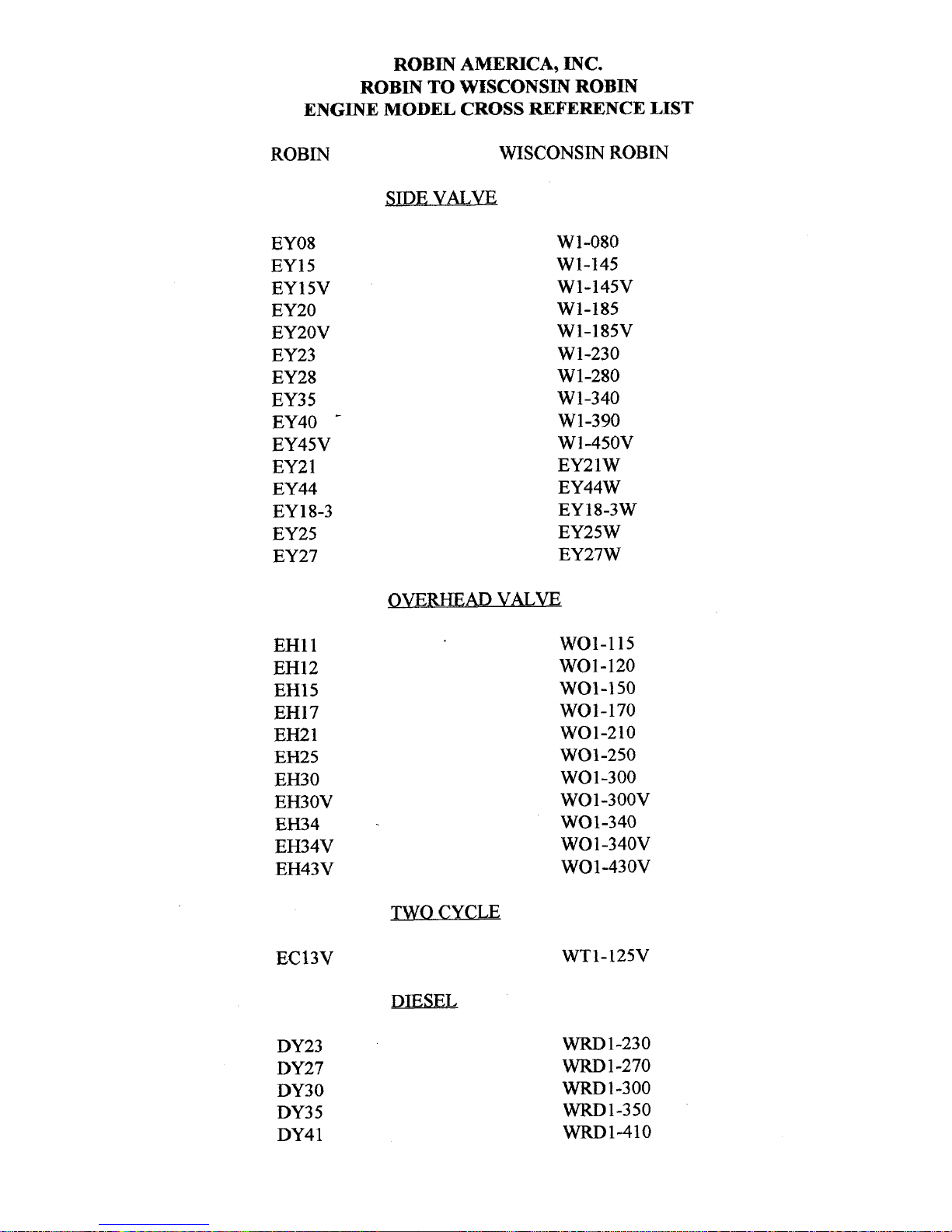
ROBIN
AMERICA, INC.
ROBIN
TO
WISCONSIN
ROBIN
ENGINE
MODEL
CROSS REFERENCE
LIST
ROBIN
EY08
EY15
EY 15V
EY20
EY2OV
EY23
EY28
EY3
5
EY40
-
EY45V
EY2
1
EY44
EY 18-3
EY25
EY27
EH11
EH12
EH15
EH17
EH21
EH25
EH30
EH30V
EH34
EH34V
EH43V
EC13V
DY23
DY27
DY30
DY3
5
DY4 1
WISCONSIN
ROBIN
SIDE
VALVE
W
1-080
W1-145
W1-145V
W1-185
W1-185V
W1-230
W 1-280
W
1-340
W 1-390
Wl-45OV
EY21W
EY44W
EY18-3W
EY25W
EY27W
OVERHEAD
VALVE
WO1-115
wo1-120
WO1-150
WO1-170
wo1-210
WOl-250
WO 1-300
WO1-300V
WO1-340
WO
1
-340V
WO 1-43 OV
TWO CYCLE
WT1-125V
DIESEL
WRD
1-230
WRD
1-270
-1-300
WRD1-350
WRD1-410
0
0
0
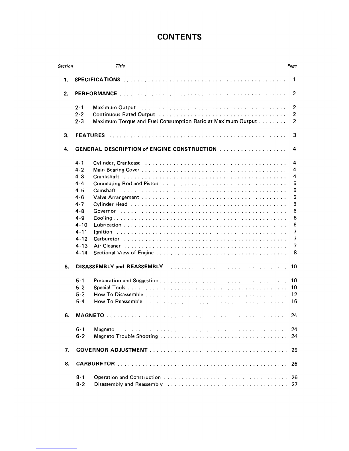
CONTENTS
Section
Title
Page
1
.
SPECIFICATIONS
..............................................
1
2
.
PERFORMANCE
...............................................
2
2-1
Maximum Output
..........................................
2
2-2
Continuous Rated Output
....................................
2
2-3
Maximum Torque and Fuel Consumption Ratio
at
Maximum Output
........
2
3
.
FEATURES
..................................................
3
4
.
GENERAL DESCRIPTION
of
ENGINE CONSTRUCTION
...................
4
4-1
4-2
4-3
4-4
4-5
4-6
4-7
4-8
4-9
4-10
4-1 1
4-12
4-13
4-14
Cylinder. Crankcase
........................................
4
Main Bearing Cover
.........................................
4
Crankshaft
..............................................
4
Connecting Rod and Piston
...................................
5
Camshaft
...............................................
5
Valve Arrangement
.........................................
5
Cylinder Head
............................................
6
Governor
...............................................
6
Cooling
.................................................
6
Lubrication
..............................................
6
Ignition
................................................
7
Carburetor
..............................................
7
Air Cleaner
..............................................
7
Sectional View
of
Engine
.....................................
8
5
.
DISASSEMBLY
and
REASSEMBLY
..................................
10
5-
1
Preparation and Suggestion
....................................
10
5-2
Special Tools
.............................................
10
5-3
How
To
Disassemble
........................................
12
5-4
How
To
Reassemble
........................................
16
6
.
MAGNETO
...................................................
24
6-1
Magneto
................................................
24
6-2
Magneto Trouble Shooting
....................................
24
7
.
GOVERNOR ADJUSTMENT
.......................................
25
8
.
CARBURETOR
................................................
26
8-1
Operation and Construction
...................................
26
8-2 Disassembly and Reassembly
..................................
27
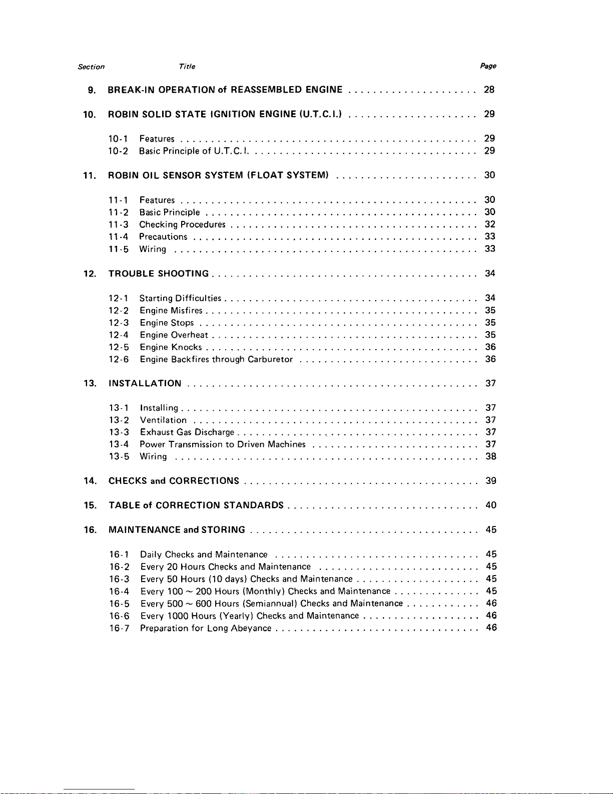
Section
Title
Page
9
.
BREAK-IN OPERATION
Of
REASSEMBLED ENGINE
.....................
28
10
.
ROBIN SOLID STATE IGNITION ENGINE (U.T.C.I.)
.....................
29
10-1
Features
................................................
29
10-2
Basic Principle of U.T.C.
I
.....................................
29
I1
.
ROBIN OIL SENSOR SYSTEM (FLOAT
SYSTEM)
.......................
30
11-1
Features
................................................
30
11
-2
Basic Principle
............................................
30
11
-3
Checking Procedures
........................................
32
11
-4
Precautions
..............................................
33
11-5
Wiring
.................................................
33
12
.
TROUBLE SHOOTING
...........................................
34
12-
1
Starting Difficulties
.........................................
34
12-2
Engine Misfires
............................................
35
12-4
Engine Overheat
...........................................
35
12-3
Enginestops
.............................................
35
12-5 Engine Knocks
............................................
36
12-6
Engine Backfires through Carburetor
.............................
36
13
.
INSTALLATION
...............................................
37
13-1
Installing
................................................
37
13-2
Ventilation
..............................................
37
13-3
Exhaust Gas Discharge
.......................................
37
13-4
Power Transmission to Driven Machines
...........................
37
13-5
Wiring
.................................................
38
14
.
CHECKS
and
CORRECTIONS
......................................
39
15
.
TABLE
of
CORRECTION STANDARDS
...............................
40
16
.
MAINTENANCE
and
STORING
.....................................
45
16-1
Daily Checks and Maintenance
.................................
45
16-2
Every
20
Hours Checks and Maintenance
..........................
45
16-3
Every
50
Hours
(IO
days)
Checks and Maintenance
....................
45
16-4
Every
100
.
200
Hours (Monthly) Checks and Maintenance
..............
45
16-5
Every
500
.
600
Hours (Semiannual) Checks and Maintenance
............
46
16-6
Every
1000
Hours (Yearly) Checks and Maintenance
...................
46
16-7
Preparation for Long Abeyance
.................................
46
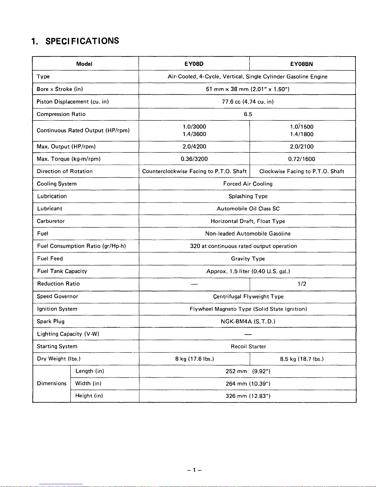
1.
SPEC1
FICATIOMS
Model
EY08BN EY08D
Air-Cooled, 4-Cycle, Vertical, Single Cylinder Gasoline Engine
Bore x Stroke (in)
77.6 cc (4.74 cu. in) Piston Displacement (cu. in)
51
mm
'x
38
mm
(2.01"
x
1.50")
Compression Ratio
6.5
Continuous Rated Output (HP/rpm)
1.0/3000
1.4/3600
1
.O?
1 500
1.4/1800
Max. Output (HP/rpm)
0.72/1600 0.36/3200
Max. Torque (kg-m/rpm)
2.0/2
1
00
2.0/4200
Direction of Rotation
1
Counterclockwise Facing to P.T.O. Shaft
Clockwise Facing to P.T.O. Shaft
Cooling System
I
Forced Air Cooling
~
Lubrication
Splashing Type
Lubricant
Automobile Oil Class
SC
~~
Carburetor
Horizontal Draft, Float Type
~~
Fuel
320
at
continuous rated output operation Fuel Consumption Ratio (gr/Hp-h)
Non-leaded Automobile Gasoline
Fuel Feed
I
Gravity Type
Fuel
Tank
Capacity
I
Approx.
1.5
liter (0.40
U.S.
gal.)
Reduction Ratio
I
-
1
/2
Speed Governor
8.5 kg (18.7 Ibs.)
8 kg (17.6 Ibs.)
Dry Weight (Ibs.)
Recoil Starter
Starting System
-
Lighting Capacity (V-W)
NGK-BM4A (S.T.D.)
Spark Plug
Flywheel Magneto Type (Solid
State
Ignition) Ignition System
Centrifugal Flyweight Type
Length (in)
326
mm
(12.83")
Height
(in)
264
mm
(10.39")
Width (in)
Dimensions
252 mrn (9.92")
-1
-
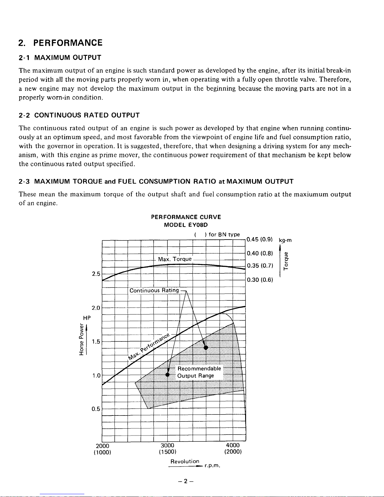
2.
PERFORMANCE
2-1
MAXIMUM OUTPUT
The maximum output of an engine
is
such standard power as developed by the engine, after its initial break-in
period with all the moving parts properly worn in, when operating with a fully open throttle valve, Therefore,
a new engine may not develop the maximum output in the beginning because the moving parts are not in a
properly worn-in condition.
2-2
CONTINUOUS RATED OUTPUT
The continuous rated output of an engine
is
such power as developed
by
that engine when running continuously at an optimum speed, and most favorable from the viewpoint of engine life and fuel consumption ratio,
with the governor in operation. It is suggested, therefore, that when designing a driving system
for
any mech-
anism, with this engine
as
prime mover, the continuous power requirement
of
that mechanism be kept below
the continuous rated output specified.
2-3
MAXIMUM TORQUE
and
FUEL CONSUMPTION
RATIO
at
MAXIMUM OUTPUT
These mean the maximum torque of the output shaft and fuel consumption ratio at the maxiumum output
of
an
engine.
HP
L
W
0
a
3’
L
0
I
PERFORMANCE
CURVE
MODEL
EY08D
( )
for
BN
type
0.45
0.40
0.35
0.30
2.5
2.0
1.5
1
.o
0.5
2000
3000
4000
(1
000)
(1
500)
(2000)
Revolution
-
r.p.m.
(0.9)
kg-rn
-2-
3.
FEATURES
1.
Compact, lightweight, durable, powerful 4cycle air cooled engine embodying ingenious design techniques
and skilful workmanship.
2.
Simple construction, smart appearance, maximum easiness
of
start owing to automatic decompression
device
3.
Pointless Solid State ignition system is newldy adopted for preventing poor igniting.
4.
Reliable prime mover for varietyof purposes with smooth speed controlrby a governor under varying load
conditions.
5.
Economical because fuel consumption is very low
-3-
4.
GENERAL DESCRIPTION
of
ENGINE CONSTRUCTION
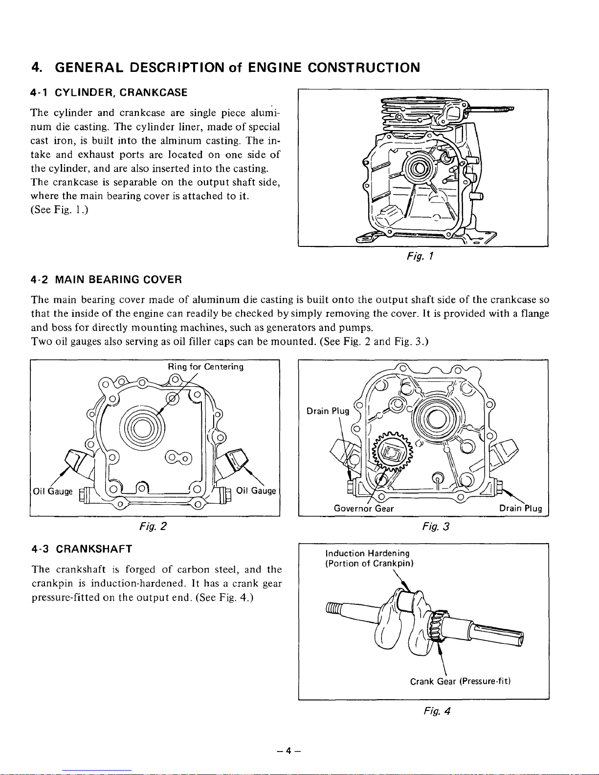
4-1
CYLINDER, CRANKCASE
The cylinder and crankcase are single piece aluminum die casting. The cylinder liner, made of special
cast iron, is built into the alminum casting. The
in-
take and exhaust ports are located on one side
of
the cylinder, and are also inserted into the casting.
The crankcase is separable on the output shaft side,
where the main bearing cover
is
attached to it.
(See Fig.
1
.)
Fig.
1
4-2
MAIN
BEARING
COVER
The main bearing cover made
of
aluminum die casting is built onto the output shaft side
of
the crankcase
so
that the inside of the engine can readily be checked by simply removing the cover. It is provided with a flange
and boss for directly mounting machines,
such
as
generators and pumps.
Two oil gauges also serving
as
oil filler caps can be mounted. (See
Fig.
2
and
Fig.
3.)
Oi
I
Ring
for Centering
!ID
Oil
Gauge
Fig.
2
4-3
CRANKSHAFT
The crankshaft is forged of carbon steel, and the
crankpin
is
induction-hardened. It has a crank gear
pressure-fitted on the output end. (See
Fig.
4.)
Fig.
3
~~
Induction Hardening
(Portion of Crankpin)
\
Crank Gear (Pressure-fit)
Fig.
4
-4-
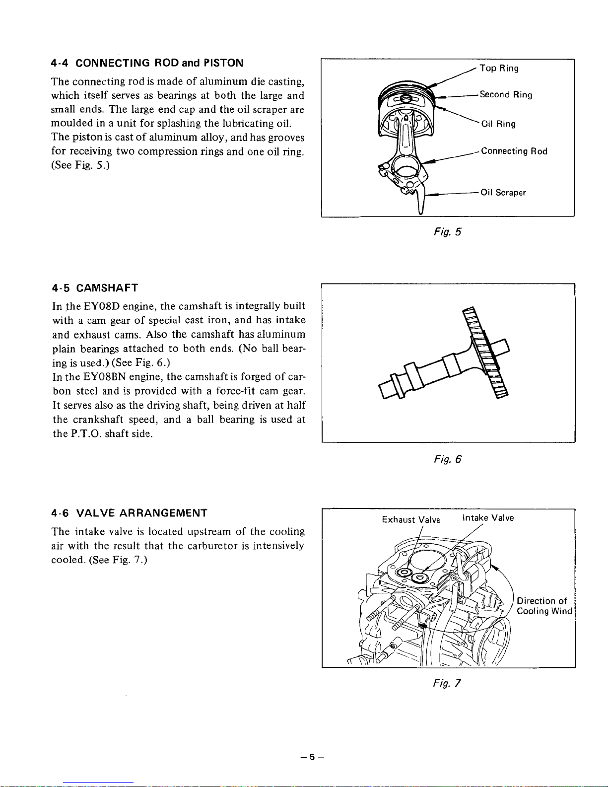
The connecting rod is made of aluminum die casting,
which itself serves as bearings at both the large and
small ends. The large end cap and the oil scraper are
moulded in a unit for splashing the lubricating oil.
The piston is cast
of
aluminum alloy, and has grooves
for receiving two compression rings and one
oil
ring.
(See Fig.
5.)
4-4
CONNECTING ROD
and
PISTON
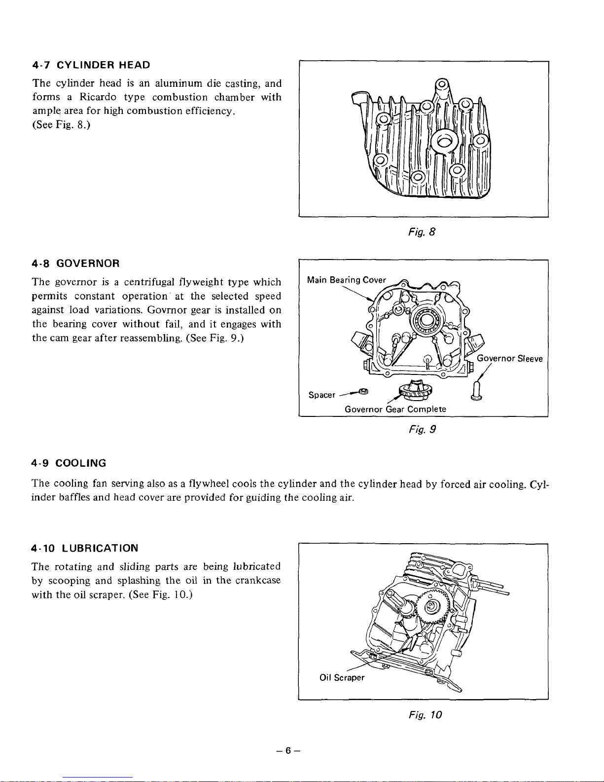
4-5 CAMSHAFT
In the EY08D engine, the camshaft is integrally built
with a cam gear of special cast iron, and has intake
and exhaust cams. Also the camshaft has aluminum
plain bearings attached to both ends.
(No
ball bear-
ing is used.) (See Fig.
6.)
In the EY08BN engine, the camshaft is forged of carbon steel and is provided with a force-fit cam gear.
It serves also
as
the driving shaft, being driven at half
the crankshaft speed, and a ball bearing is used at
the P.T.O. shaft side.
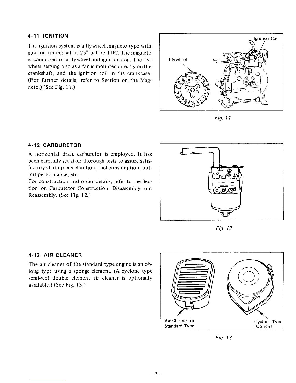
4-6
VALVE ARRANGEMENT
The intake valve is located upstream
of
the cooling
air with the result that the carburetor is intensively
cooled. (See Fig.
7.)
Top
Ring
Second Ring
Oil
Ring
Connecting
Rod
Oil
Scraper
\I
L
Fig.
5
:
Fig.
6
Direction
of
Cooling
Wind
Fig.
7
-5-
4-7
CYLINDER HEAD
The cylinder head
is
an aluminum die casting, and
forms a Ricardo type combustion chamber with
ample area for high combustion efficiency.
(See
Fig.
8.)
4-8
GOVERNOR
The governor is a centrifugal flyweight type which
permits constant operation- at the selected speed
against load variations. Govrnor gear is installed on
the bearing cover without fail, and
it
engages with
the cam gear after reassembling. (See Fig.
9.)
I
Fig.
8
Main
Be
!mor
Sleeve
Spacer
Q
-
Governor Gear Complete
Fig.
9
4-9
COOLING
The cooling fan serving also as a flywheel cools the cylinder and the cylinder head by forced air cooling. Cylinder baffles
and
head cover are provided for guiding the cooling air.
4-10
LUBRICATION
The rotating and
sliding
parts are being lubricated
by scooping
and
splashing the
oil
in the crankcase
with the
oil
scraper. (See Fig.
10.)
Fig.
10
-6-
4-11
IGNITION
The ignition system
is
a flywheel magneto type with
ignition timing set at
25"
before TDC. The magneto
is composed
of
a
flywheel and ignition coil. The fly-
wheel serving also as a fan is mounted directly on the
crankshaft, and the ignition coil in the crankcase.
(For further details, refer to Section
on
the Mag-
neto.) (See
Fig.
1 1
.)
4-12 CARBURETOR
A
horizontal draft carburetor is employed. It has
been carefully set after thorough tests to assure satisfactory start up, acceleration, fuel consumption, output performance, etc.
For construction and order details, refer to the Section on Carburetor Construction, Disassembly and
Reassembly. (See Fig. 12.)
4-13 AIR CLEANER
The air cleaner
of
the standard
ty
:ngine
is
an
0
b-
long type using a sponge element.
(A
cyclone type
semi-wet double element air cleaner is optionally
available.) (See
Fig.
13.)
I
Ignition Coil
Fig.
1
1
Fig.
12
Air Cieaner for
Standard Type
Cyclone Type
(Option)
Fig.
13
-7-
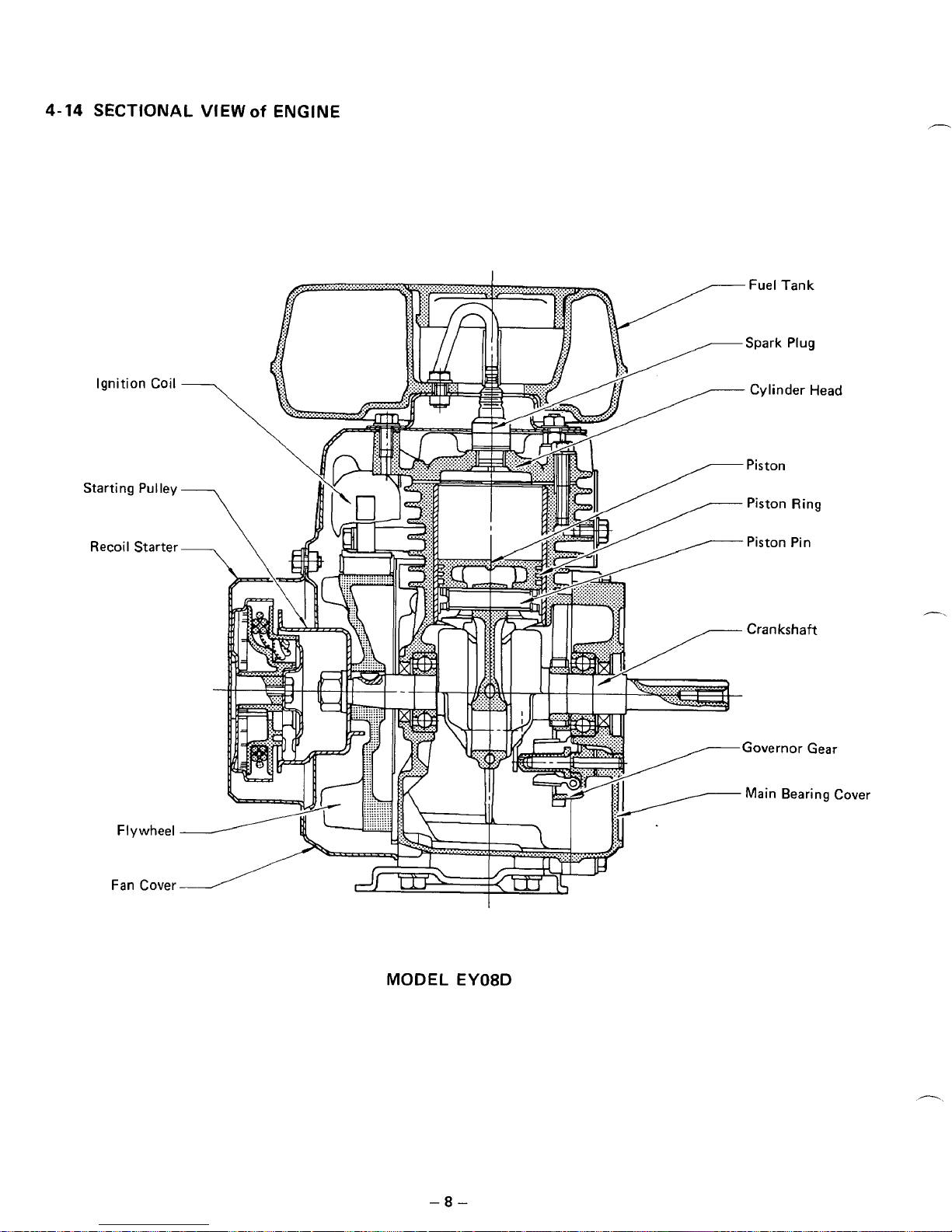
4-14
SECTIONAL
VIEW
of
ENGINE
MODEL
-8-
EY08D
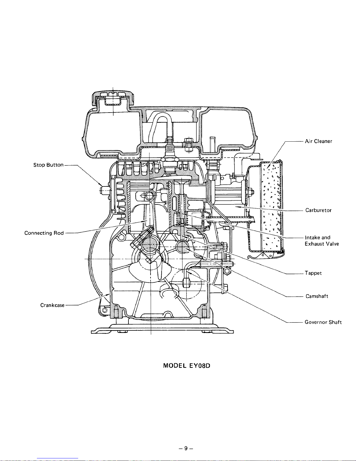
Stop Button
Connecting
Rod
Crankcase
MODEL
EY08D
Air
Cleaner
Carburetor
Intake and
Exhaust Valve
Tappet
Camshaft
Governor
Shaft
-9-
5.
DISASSEMBLY
and
REASSEMBLY
5-1
PREPARATIONS
and
SUGGESTIONS
1)
When disassembling the engine, remember well the locations of individual parts
so
that they can be reas-
sembed correctly.
If
you are uncertain
of
identifying some parts, it
is
suggested that tags be attached
to
them.
2)
Have boxes ready
to
keep disassembed parts by group.
3)
To
prevent missing and misplacing, temporarily assemble each group of disassembed parts.
4)
Carefully handle disassembed parts, and clean them with washing oil.
5)
Use the correct tools
in
the correct way.
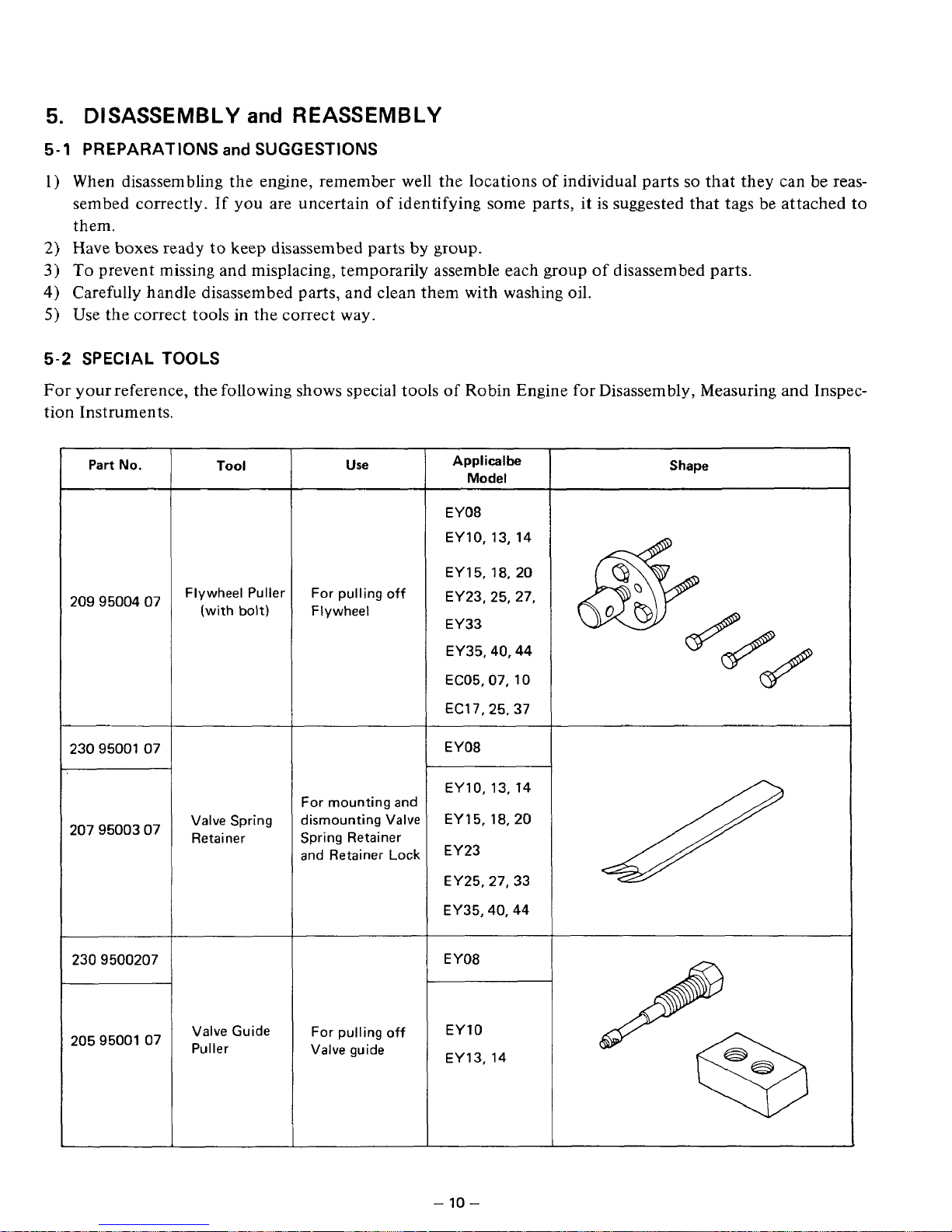
5-2
SPECIAL
TOOLS
For
your reference, the following shows special tools of Robin Engine for Disassembly, Measuring and Inspec-
tion Instruments.
Part
No.
2099500407
2309500107
2079500307
2309500207
2059500107
Tool
Flywheel Puller
(with
bolt)
Valve Spring
Retainer
Valve Guide
Puller
Use
For pulling
off
Flywheel
For mounting and
dismounting Valve
Spring Retainer
and Retainer
Lock
For pulling off
Valve guide
Applicalbe
Model
EY08
EY10, 13, 14
EY
15,18,
20
EY23, 25, 27,
EY33
EY35,40,44
EC05.07, 10
EC17,25.37
EY08
EY10,13, 14
EY 15, 18,20
EY23
EY25.27, 33
EY35,40,44
EY08
EY10
EY13,
14
Shape
-10-
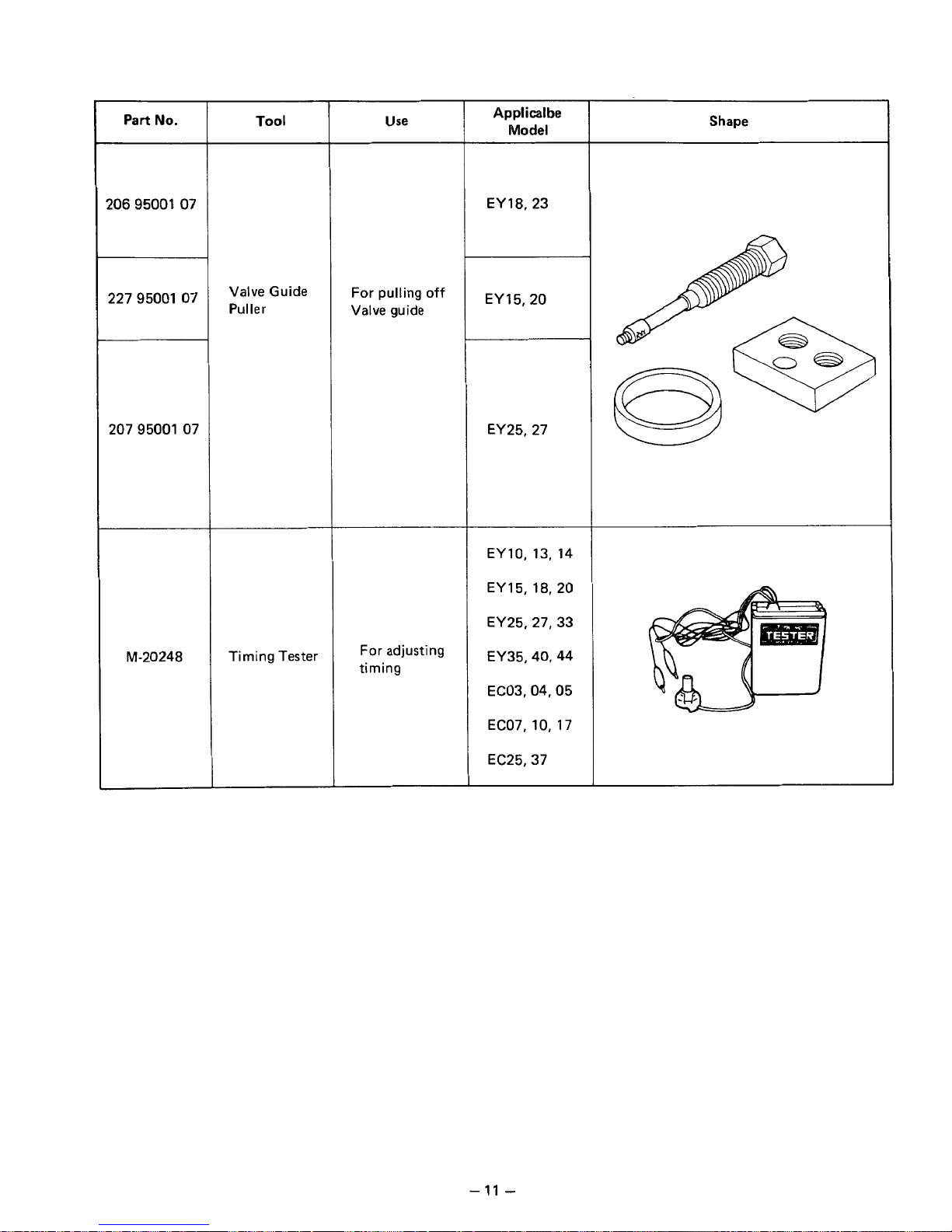
Part
No.
2069500107
2279500107
207 95001 07
“20248
Tool
Valve Guide
Puller
Timing Tester
Use
For pulling
off
Valve guide
For
adjusting
timing
Applicalbe
Model
EY18.23
EY 15,ZO
EY25, 27
EY10,
13,
14
EY 15, 18,20
EY25,27,33
EY35,40,44
EC03,04,05
EC07,10,
17
EC25,37
Shape
-
11
-
5-3
HOW
TO
DISASSEMBLE
*Length of the bolt indicates the length from the bolt head bottom surface to the threaded end.
Order
5
I
tern
Fuel tank
Recoil starter
Tank bracket
Head cover
Fan cover
Muffler cover
Muffler
Air cleaner
Procedures
(1)
Close the fuel cock.
(2)
Disconnect the fuel pipe between the fuel
strainer and carburetor at the carburetor
side.
(3) Remove the fuel tank from the tank bracket.
M6
x
14
mm bolt
:
3
pcs.
(1)
Remove the recoil starter.
M6
x
8
mm bolt
:
3
pcs.
(1)
Remove the
tank
bracket, the head cover,
and the fan cover from the crankcase and
the cylinder head.
M6
x
10
rnm
bolt
:
2
pcs.
M6
x
12
bolt
:
1
pce.
M6 nut
:
2
pcs.
(1)
Remove the muffler cover 1 from the
muffler.
M6
x
8
mm bolt
:
2
pcs.
(2)
Remove the muffler from the cylinder
portion
of
the crankcase.
M6
x
28
mrn bolt
:
1
pce.
M6
x
50 mm bolt
:
1
pce.
(1)
Remove the air cleaner cover and the
(2)
Remove the
air
cleaner case from the
element.
carburetor.
M6 nut
:
2
pcs.
(3) Disconnect the breather pipe.
Remarks
Sems bolt
Fastened together
Remove the primary
wire of the stop button.
Air cleaner is fastened together with the
carburetor.
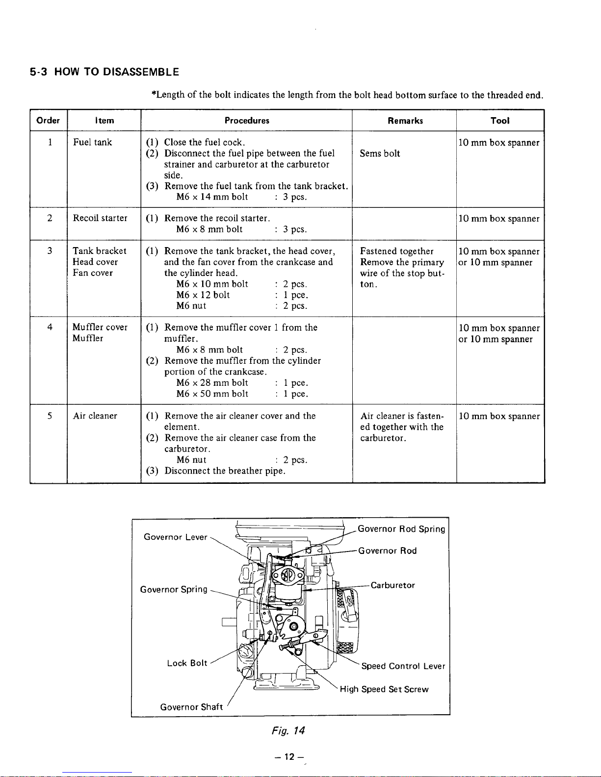
Governor Lever
Governor Spring
Lock
Bolt
{--)
,Governor Rod Spring
Governor
Rod
Lever
L
'
High
Speed Set
Screw
Governor
Shaft
Fig.
14
Tool
10
mm box spanner
IO
mm box spanner
10
m
box spanner
Ir
10
mm spanner
10
mm box spanner
x
10
mm
spanner
10
mm box spanner
-
12
-
 Loading...