

Page 1

SERVICE
MANUAL
Model
EH65
Engine
PUB-ES1113
Rev. 8/98
Page 2

940 Lively Blvd. Wood Dale, IL 60191 Phone: 630-350-8200 Fax: 630-350-8212
e-mail: sales@robinamerica.com • www.robinamerica.com
© Copyright 1998 Robin America, Inc.
EH65 '98 - 8
Page 3

CONTENTS
Section Title Page
1. SPECIFICATIONS.......................................................................................................1
2. PERFORMANCE ........................................................................................................2
2-1 MAXIMUM OUTPUT ......................................................................................................... 2
2-2 CONTINUOUS RATED OUTPUT ..................................................................................... 2
2-3 MAXIMUM TORQUE ........................................................................................................ 2
2-4 PERFORMANCE CURVES .............................................................................................. 3
3. FEATURES..................................................................................................................6
4. GENERAL DESCRIPTION OF ENGINE COMPONENTS .......................................... 7
4-1 CYLINDER AND CRANKCASE........................................................................................ 7
4-2 MAIN BEARING COVER .................................................................................................. 7
4-3 CRANKSHAFT..................................................................................................................7
4-4 CONNECTING ROD AND PISTON .................................................................................. 8
4-5 PISTON RINGS ................................................................................................................8
4-6 CAMSHAFT ...................................................................................................................... 8
4-7 CYLINDER HEAD............................................................................................................. 9
4-8 VALVE ARRANGEMENT .................................................................................................. 9
4-9 GOVERNOR SYSTEM ..................................................................................................... 9
4-10 COOLING SYSTEM...................................................................................................... 10
4-11 LUBRICATION SYSTEM............................................................................................... 10
4-12 IGNITION SYSTEM ...................................................................................................... 10
4-13 CHARGING SYSTEM ................................................................................................... 10
4-14 CARBURETOR ..............................................................................................................11
4-15 AIR CLEANER ...............................................................................................................11
4-16 FUEL PUMP...................................................................................................................11
4-17 SECTIONAL VIEW OF ENGINE................................................................................... 12
5. DISASSEMBLY AND REASSEMBLY....................................................................... 14
5-1 PREPARATIONS AND SUGGESTIONS......................................................................... 14
5-2 SPECIAL TOOLS............................................................................................................ 14
5-3 DISASSEMBLY PROCEDURES..................................................................................... 15
5-4 REASSEMBLY PROCEDURES...................................................................................... 30
5-5 BREAK-IN OPERATION................................................................................................. 43
6. MAGNETO ................................................................................................................ 44
6-1 OPERATION AND FUNCTION ....................................................................................... 44
Page 4

Section Title Page
7. LUBRICATION SYSTEM ......................................................................................... 46
7-1 OPERATION AND FUNCTION .......................................................................................46
8. CARBURETOR ........................................................................................................ 47
8-1 OPERATION AND FUNCTION .......................................................................................47
8-2 COMPORNENT PARTS .................................................................................................49
9. ELECTRIC STARTER .............................................................................................. 50
9-1 OPERATION AND FUNCTION .......................................................................................50
9-2 COMPORNENT PARTS .................................................................................................51
10. TROUBLESHOOTING ........................................................................................... 52
10-1. NO ENGINE OPERATION ...........................................................................................52
10-2. STARTING DIFFICULTIES .........................................................................................53
10-3. INSUFFICIENT OUTPUT.............................................................................................54
10-4. OVERHEAT..................................................................................................................54
10-5. ROUGH IDLING...........................................................................................................55
10-6. HIGH ENGINE OIL CONSUMPTION...........................................................................55
10-7. HIGH FUEL CONSUMPTION ......................................................................................56
10-8. DETONATION..............................................................................................................56
10-9. ENGINE MISFIRE........................................................................................................57
11. INSTALLATION ..................................................................................................... 58
11-1 INSTALLING..................................................................................................................58
11-2 VENTILATION...............................................................................................................58
11-3 EXHAUST GAS DISCHARGE ......................................................................................58
11-4 POWER TRANSMISSION TO DRIVEN MACHINES ....................................................58
12. SERVICE DATA...................................................................................................... 59
12-1 CLEARANCE DATA AND LIMITS.................................................................................59
12-2 TORQUE SPECIFICATIONS ........................................................................................65
12-3 OIL GRADE CHART .....................................................................................................66
13. MAINTENANCE AND STORAGE.......................................................................... 67
13-1 DAILY MAINTENANCE .................................................................................................67
13-2 PERIODIC MAINTENANCE SCHEDULE.....................................................................67
13-3 ENGINE STORAGE......................................................................................................69
Page 5

1. SPECIFICATIONS
LEDOMD36HED46HED56HE
epyT
ekortsxeroB )mm56xmm08(ni65.2xni51.3-2
tnemecalpsiDni.uc9.93
oitaRnoisserpmoC3.8
tuptuosounitnoC
mpr/)PH(Wk
tuptuomumixaM
mpr/)PH(Wk
mpr/)m-fgk(m-NeuqroT.xaM000,2/)14.4(3.34002,2/)25.4(3.44005,2/)56.4(6.54
noitatoRfonoitceriD edistfahs.O.T.PmorfdeweivsaesiwkcolcretnuoC
metsySgnilooC gnilooCriAdecroF
stnemegnarrAevlaV )VHO(evlaVdaehrevO
noitacirbuL pmuPdiohcorThtiwepyteruserplluF
tnacirbuL
.
3
mc356(
)
006,3/)5.41(8.01006,3/)0.61(9.11006,3/)0.71(4.31
006,3/)0.81(4.31006,3/)5.02(3.51006,3/)0.22(4.61
rehgihroESssalC
,rednilyCniwT-V,ekortS-4,delooC-riA
enignEenilosaGVHO,tfahs.O.T.PlatnoziroH
;03-W01ro03#,02#EASliOenignEelibomotuA
tnacirbuLfoyticapaC )sretiL55.1(.zo84.25
roterubraC epyTtaolF,tfahSlatnoziroH
leuF enilosaGdedaelnUelibomotuA
metsySdeeFleuF )epytesluP(pmuPmgarhpaiD
metsySnoitingI )etatSdiloS(otengaMleehwylF
gulPkrapS )CY9N-noipmahC(SE6PB-KGN
yticapaCgnigrahCA51-V21
metsySgnitratS retratScirtcelE
metsySronrevoG epyTthgiewylFlagufirtneC
renaelCriA epyTtnemelEelbuoD
thgieWyrD )gk44(.bl0.79
)HxWxL(noisnemiD )mm574xmm774xmm713(ni7.81xni8.81xni5.21
Specifications are subject to change without notice.
- 1 -
Page 6

2. PERFORMANCE
2-1 MAXIMUM OUTPUT
The maximum output is the output of an engine with its throttle valve fully opened under the condition that
all the moving parts are properly worn in after the initial break-in period.
A new engine may not produce full maximum output while its moving parts are still not broken-in.
NOTE :
Power curves shown in the following charts are made in conformity to SAE internal combustion engine
standard test code J1349
2-2 CONTINUOUS RATED OUTPUT
The continuous rated output is the output of an engine at optimum governed speed which is most favorable from the view point of engine's life and fuel consumption.
When the engine is installed on a certain equipment, it is recommended that the continuous output
required from the engine be kept below this continuous rated output.
2-3 MAXIMUM TORQUE
The maximum torque is the torque at the output shaft when the engine is producing maximum output at
certain revolution.
- 2 -
Page 7
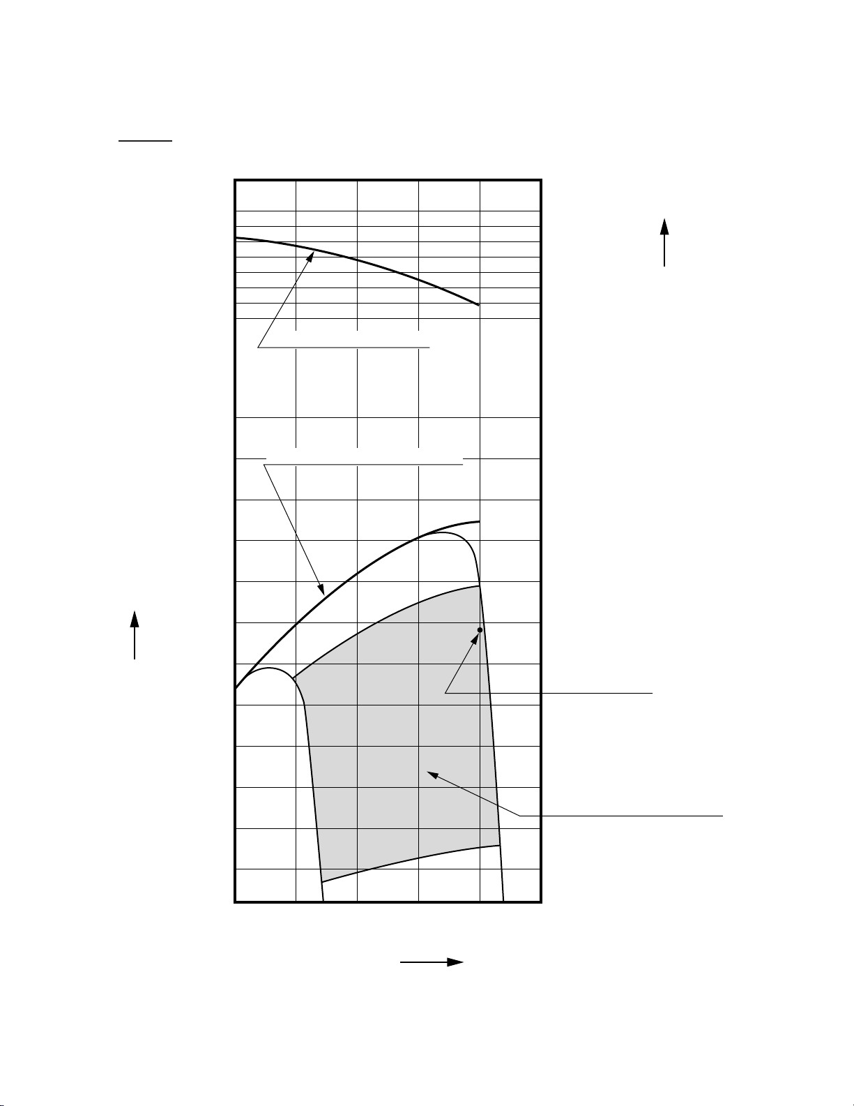
2-4 PERFORMANCE CURVES
EH63D
45 (4.59
N-m
(
)
kgf-m
)
kW
(HP)
15
(
20.1
10
(
13.4
35 (3.57
MAXIMUM TORQUE
MAXIMUM HORSEPOWER
)
)
CONTINUOUS
RATED HP
)
TORQUE
HORSEPOWER
5
(
)
6.7
2000 2400 2800 3200 3600
RECOMMENDED
HORSEPOWER RANGE
REVOLUTION r.p.m
- 3 -
Page 8
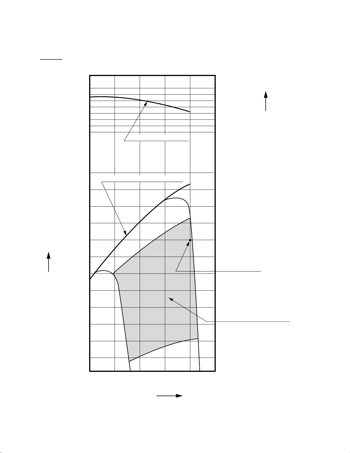
EH64D
45 (4.59
N-m
(
kgf-m
)
)
kW
(HP)
15
(
20.1
10
(
13.4
35 (3.57
MAXIMUM TORQUE
MAXIMUM HORSEPOWER
)
CONTINUOUS
RATED HP
)
)
TORQUE
HORSEPOWER
5
(
)
6.7
2000 2400 2800 3200 3600
RECOMMENDED
HORSEPOWER RANGE
REVOLUTION r.p.m
- 4 -
Page 9
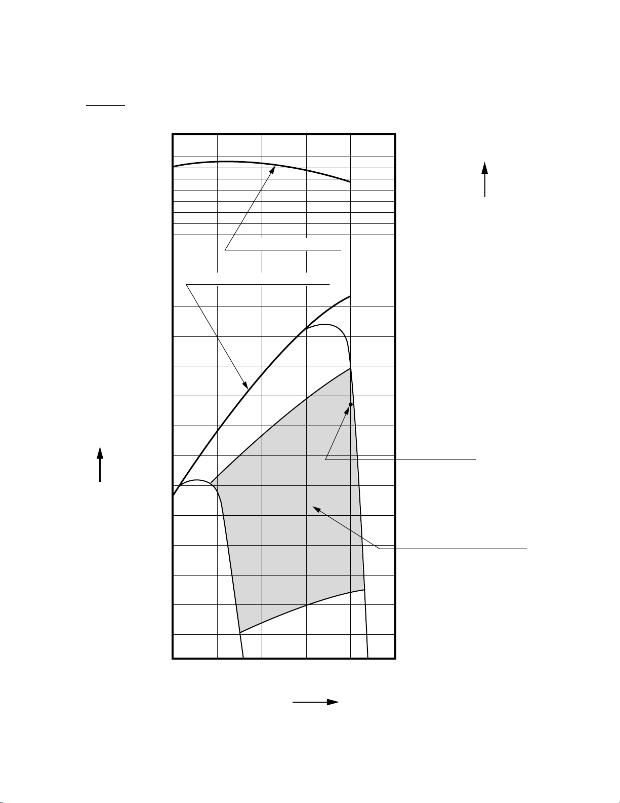
EH65D
45 (4.59
N-m
(
)
kgf-m
)
kW
(HP)
15
(
20.1
10
(
13.4
35 (3.57
MAXIMUM TORQUE
MAXIMUM HORSEPOWER
)
CONTINUOUS
RATED HP
)
)
TORQUE
HORSEPOWER
5
(
)
6.7
2000 2400 2800 3200 3600
RECOMMENDED
HORSEPOWER RANGE
REVOLUTION r.p.m
- 5 -
Page 10

3. FEATURES
The overhead valve arrangement is adopted for ensuring high power, low fuel consumption and low oil
consumption.
The adoption of twin-cylinder in the angle of 90 degree (V arrangement) and crankcase in one piece,
plastic blower housing etc. offers a compactness and light weight, making the arrangements for installing
the engine much easier into many kinds of power equipments.
The forged steel crankshaft and high loading capacity ball bearing offer high durability, and full pressure
lubrication system with trochoid type oil pump and large capacity air cleaner with dual elements enhance
the reliability.
The effective combustion chamber shape and the precisely tuned intake and exhaust valve system
enhance the low exhaust emission and ensure the engine characteristics of high torque at low speed.
The carburetor with fuel cut valve, 12V-15A alternator and pulse type fuel pump are employed as standard features so that the engine can be utilized for many usage.
- 6 -
Page 11
4. GENERAL DESCRIPTION OF ENGINE COMPONENTS
ROBIN EH63D/ 64D/ 65D series engine is air-cooled, 4-stroke, twin-cylinder, OHV arrangement gasoline engine. The twin-cylinder is located in the angle of 90 degree; #1 cylinder is in the RH side and #2
cylinder in LH side as viewed from flywheel (cooling fan) side.
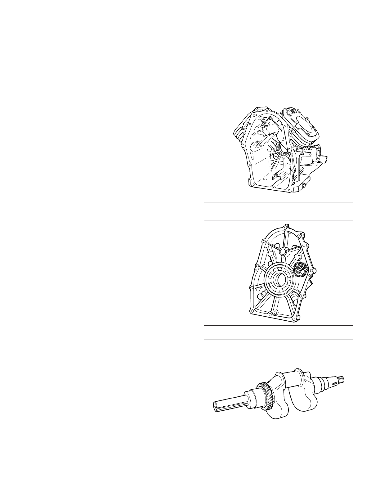
4-1 CYLINDER AND CRANKCASE
The twin-cylinder and crankcase is single piece
aluminum die-casting.
The cylinder liner, made of special cast iron, is
molded into the aluminum casting.
The crankcase has a mounting surface on the output shaft side, where the main bearing cover is
attached.
Fig. 4-1
4-2 MAIN BEARING COVER
The main bearing cover is an aluminum die-casting, which is mounted on the output shaft side of
the crankcase.
Pilots and bosses are machined on the cover for
direct mounting of the engine onto such machines
as generators and pumps.
It is easy to inspect inside of the engine, after removing the main bearing cover.
4-3 CRANKSHAFT
The crankshaft is forged carbon steel, and the
crank pin is induction-hardened.
The output end of the shaft has a crankshaft gear
pressed into position.
Engine oil passages are provided onto the journal and pin portions of crankshaft for lubrication.
Fig. 4-2
- 7 -
Fig. 4-3
Page 12
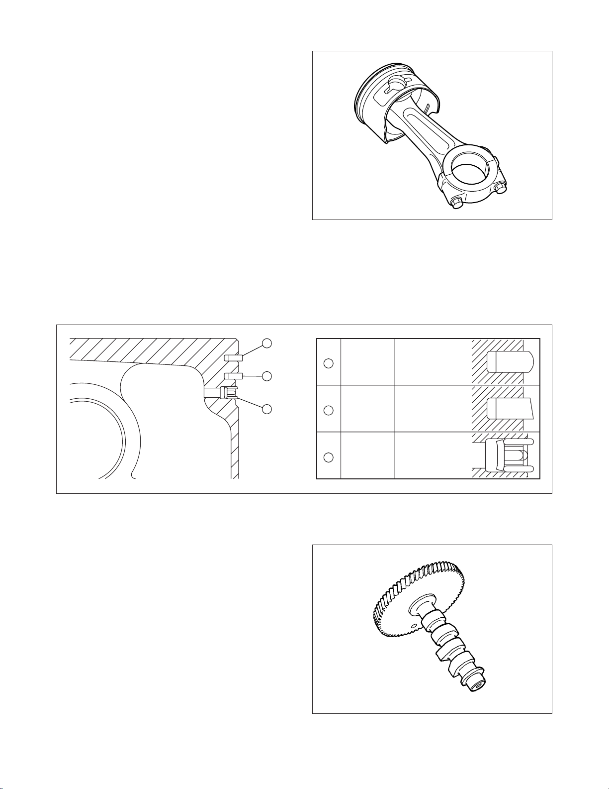
4-4 CONNECTING ROD AND PISTON
The connecting rod is forged aluminum alloy, and
its large and small ends function as bearings.
The piston is an aluminum alloy casting, and carries two compression rings and one oil ring.
Fig. 4-4
4-5 PISTON RINGS
The piston rings are made of special cast iron.
The profile of the top ring is barrel face and the second ring has a tapered face.
The oil ring is designed for better sealing and less oil consumption, in combination with 3 pieces.
1
TOP
1
2
RING
BARREL
4-6 CAMSHAFT
The camshaft is made of special cast iron and
camshaft gears are casted together in one piece.
Each 2 cam robs are provided for intake and exhaust valves correspondingly.
Both sides of the shaft fit into the plane bearings
on the crankcase and main bearing cover.
3
Fig. 4-5
2
3
SECOND
RING
OIL
RING
TAPER
COMBINATION
RING
- 8 -
Fig. 4-6
Page 13
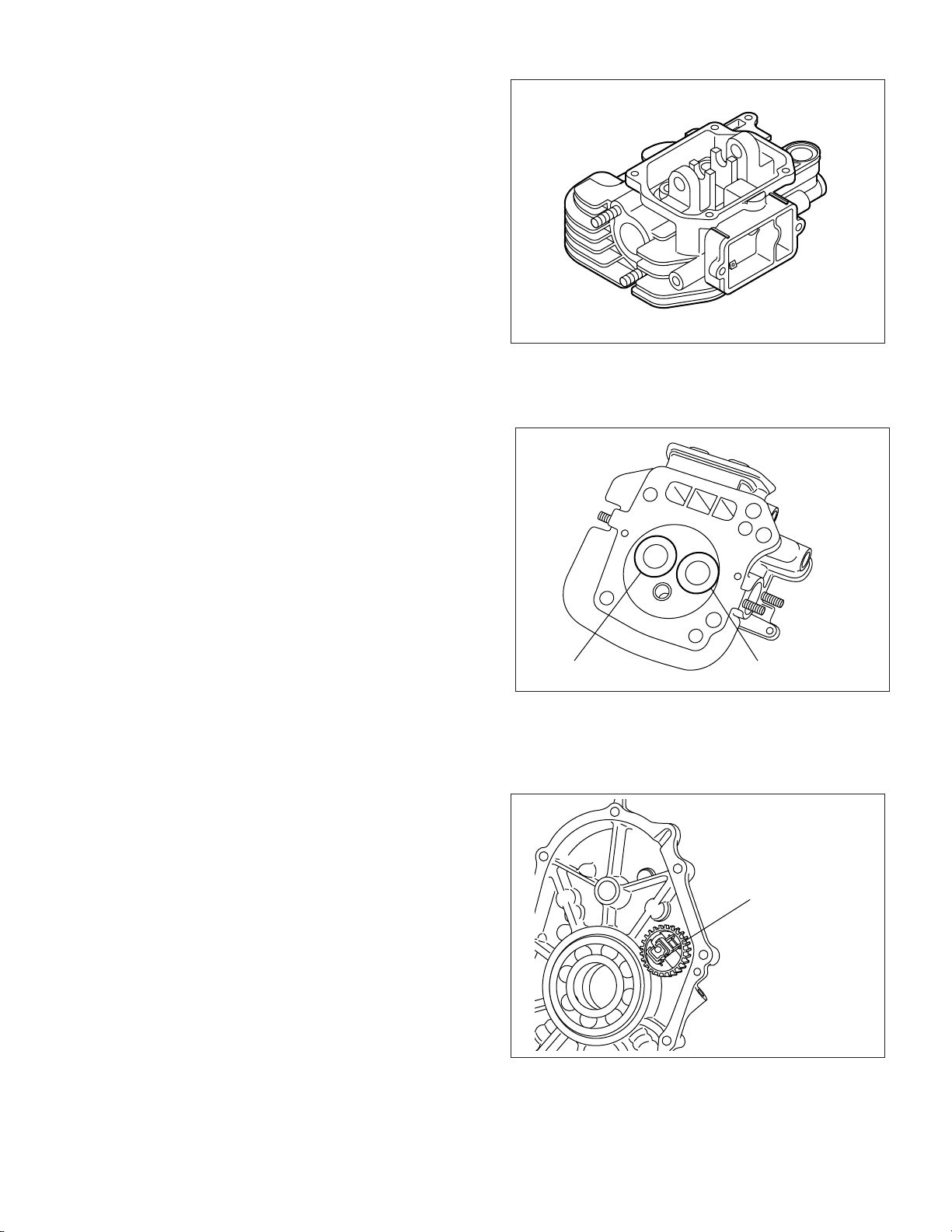
4-7 CYLINDER HEAD
The cylinder head is an aluminum die-casting
which utilizes semi-spherical type combustion
chamber for the high combustion efficiency.
4-8 VALVE ARRANGEMENT
The intake valve is located on flywheel side of the
cylinder head.
The cooling fins and passages design lead cooling air to the exhaust valve area for the optimum
cooling.
Fig. 4-7
Hard alloy valve seats are molded in the cylinder
head and stellite is fused to the exhaust valve face.
4-9 GOVERNOR SYSTEM
The governor is a centrifugal flyweight type which
ensures constant operation at the selected speed
against load variations.
The governor gear with governor weights is installed inside of main bearing cover and driven
by the crankshaft.
INTAKE VALVE EXHAUST VALVE
Fig. 4-8
GOVERNOR
GEAR
- 9 -
Fig. 4-9
Page 14
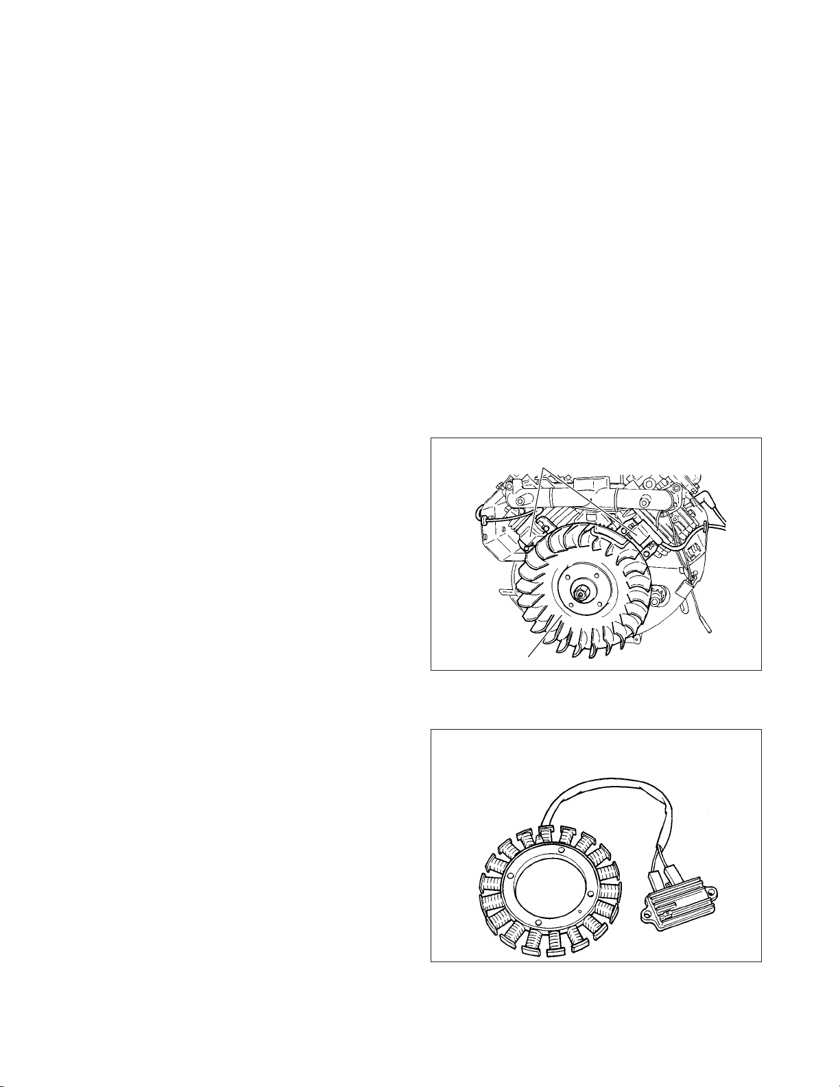
4-10 COOLING SYSTEM
The large fins on the flywheel provide sufficient
cooling air capacity for cylinder and cylinder head.
The cylinder baffle helps the cooling air flow efficiently.
4-11 LUBRICATION SYSTEM
The engine is furnished with full pressure lubrication system.
The trochoid type oil pump is driven by crankshaft
and delivers pressurized engine oil through the
full-flow type oil filter to the journal and pin portions of crankshaft and camshaft.
4-12 IGNITION SYSTEM
The ignition system is a transistor controlled magneto ignition system which consists of a flywheel
and an ignition coil with a built-in transistor installed
onto the crankcase.
IGNITION COIL
4-13 CHARGING SYSTEM
Multipolar charging coil is provided inside of flywheel. Charging capacity is 12V-15A.
FLYWHEEL
Fig. 4-10
Fig. 4-11
-
10
-
Page 15
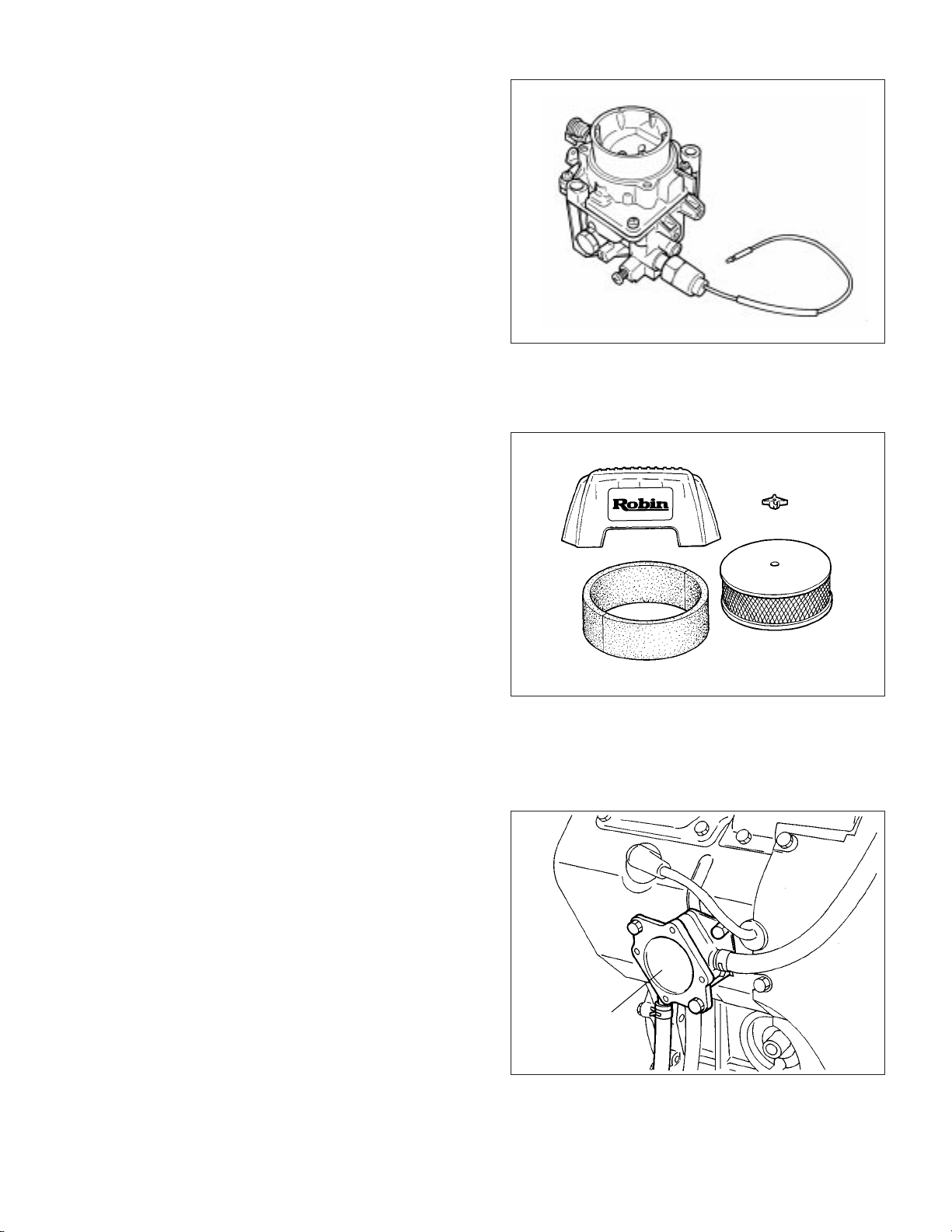
4-14 CARBURETOR
The engines are equipped with a down draft carburetor that has a float controlled fuel system and
a fixed main jet.
The carburetors are calibrated carefully for the
sure starting, good acceleration, low fuel consumption and sufficient output.
Fuel cut solenoid valve is provided to prevent engine running on when the key switch is turned to
off.
4-15 AIR CLEANER
The air-cleaner is a heavy-duty type with a dual
element system; primary side is urethane form
(half-wet) and secondary side is dry type.
Fig. 4-12
CLEANER COVER
WING NUT
4-16 FUEL PUMP
The engines are equipped with a diaphragm type
fuel pump which is operated by the crankcase inside vacuum pressure.
ELEMENT
URETHANE FOAM
Fig. 4-13
FUEL PUMP
Fig. 4-14
-
11
-
Page 16
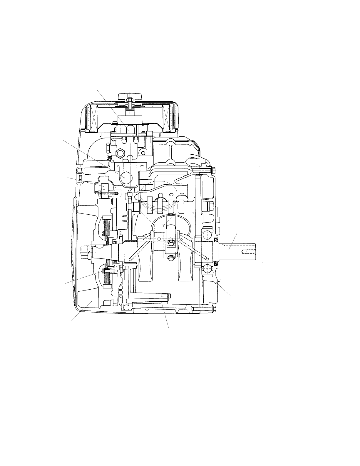
4-17 SECTIONAL VIEW OF ENGINE
CARBURETOR
INTAKE MANIFOLD
IGNITION COIL
OIL PUMP
FLYWHEEL
P.T.O.SHAFT
MAIN BEARING COVER
OIL PUMP FILTER
Fig. 4-15
-
12
-
Page 17
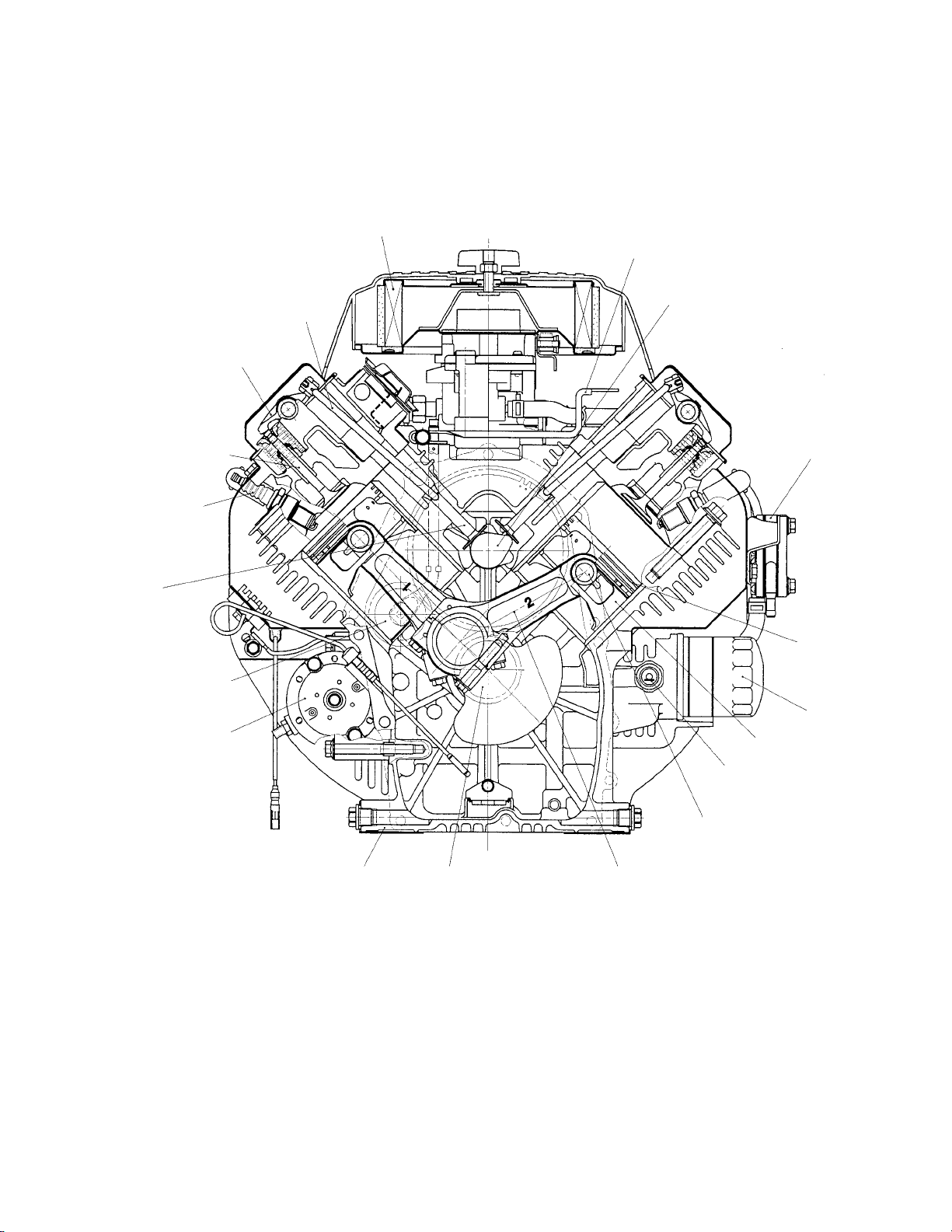
AIR CLEANER
GOVERNOR LEVER
ROCKER ARM
INTAKE AND
EXHAUST VALVES
SPARK PLUG
TAPPET
GOVERNOR GEAR
ELECTRIC STARTER
PUSH ROD
CAMSHAFT
FUEL PUMP
PISTON RING
OIL FILTER
PISTON
OIL PRESSURE
PISTON PIN
CRANKCASE CRANKSHAFT CONNECTING ROD
Fig. 4-16
-
13
-
SWITCH
Page 18
5. DISASSEMBLY AND REASSEMBLY
5-1 PREPARATIONS AND SUGGESTIONS
When disassembling the engine, memorize the locations of individual parts so that they can be reassembled correctly . If you are uncertain of identifying some parts, it is suggested that tags be attached to
them.
Have boxes ready to keep disassembled parts by group.
To prevent losing and misplacing, temporarily assemble each group of disassembled parts.
Carefully handle disassembled parts, and clean them with washing oil if necessary.
Use the correct tools in the correct way.
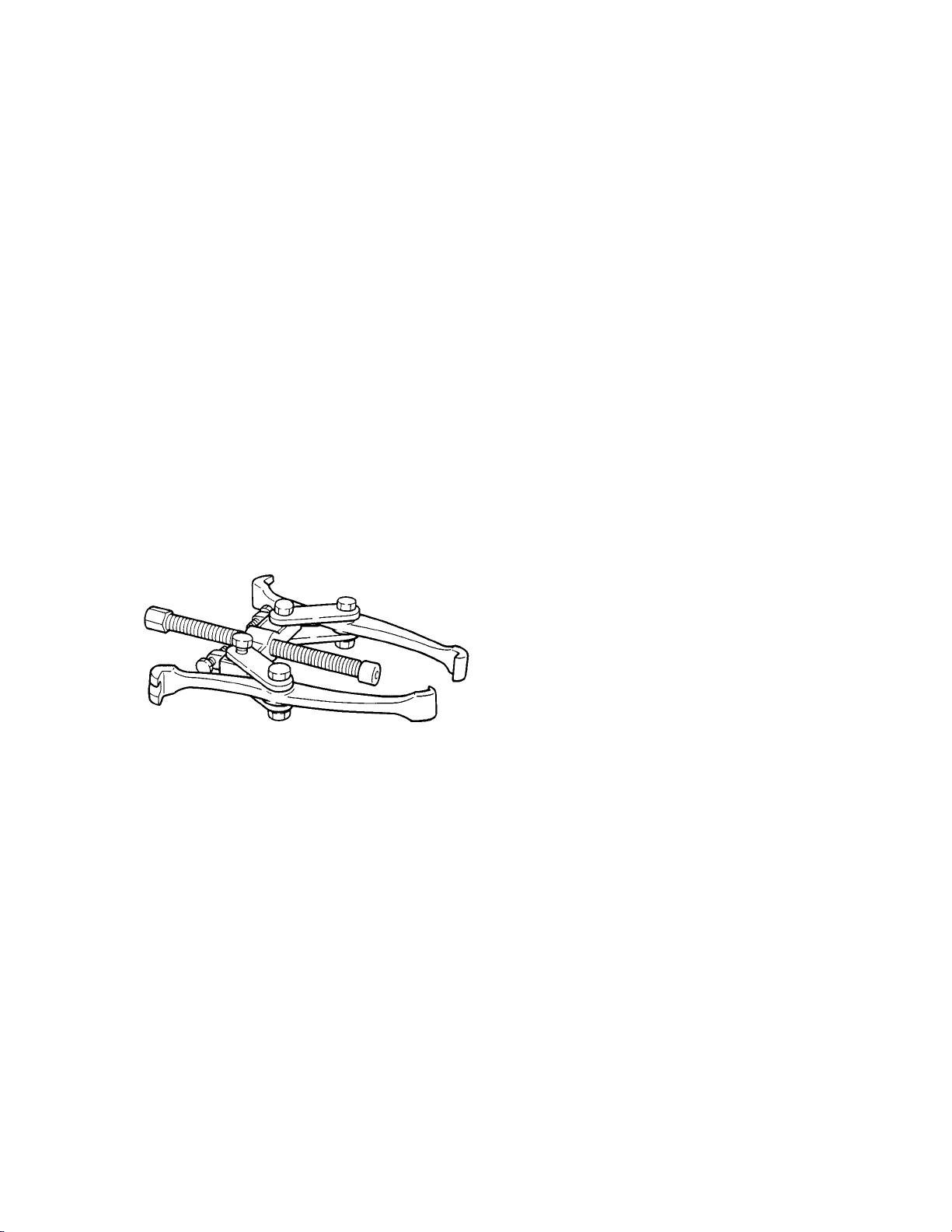
5-2 SPECIAL TOOLS
No Special Tool is needed for disassembling and reassembling the engine.
For pulling off the flywheel, universal type puller being popular in the market place as shown in the
illustration is needed.
FLYWHEEL PULLER
Fig. 5-1
-
14
-
Page 19
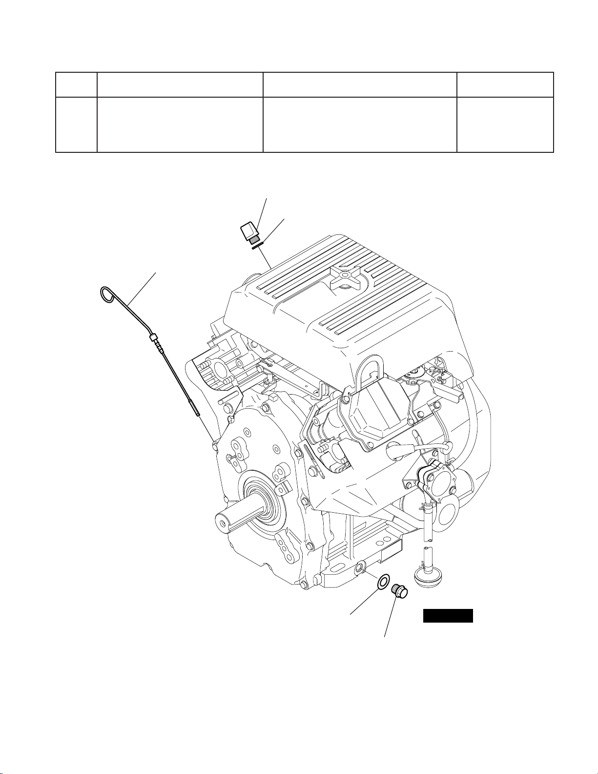
5-3 DISASSEMBLY PROCEDURES
petSevomerotstraPserudecorpdnaskrameRsrenetsaF
niardlioenignEsgulpgnivomeryblioenigneniarD
1
OIL FILLER CAP
GASKET
OIL LEVEL GAUGE
.esacknarcfoedishtobnodetacol
Fig. 5-2
-
15
GASKET
-
OIL DRAIN PLUG
(
ON BOTH SIDE
STEP 1
)
Page 20
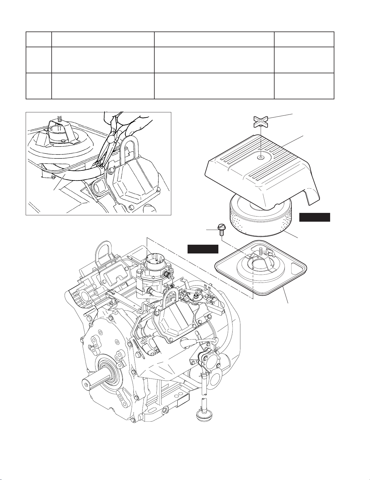
petSevomerotstraPserudecorpdnaskrameRsrenetsaF
2
3esabrenaelcriA
BREATHER
PIPE
Fig. 5-4
stnemelednarevocrenaelcriA1#morfepiprehtaerbevomeR
FLANGE BOLT
(
) :
Inch
3 pcs.
STEP 3
;mm11x23-01
.daehrednilyc
.scp3
WING NUT
CLEANER
COVER
STEP 2
CLEANER
ELEMENT
Fig. 5-3
-
16
CLEANER BASE
-
Page 21
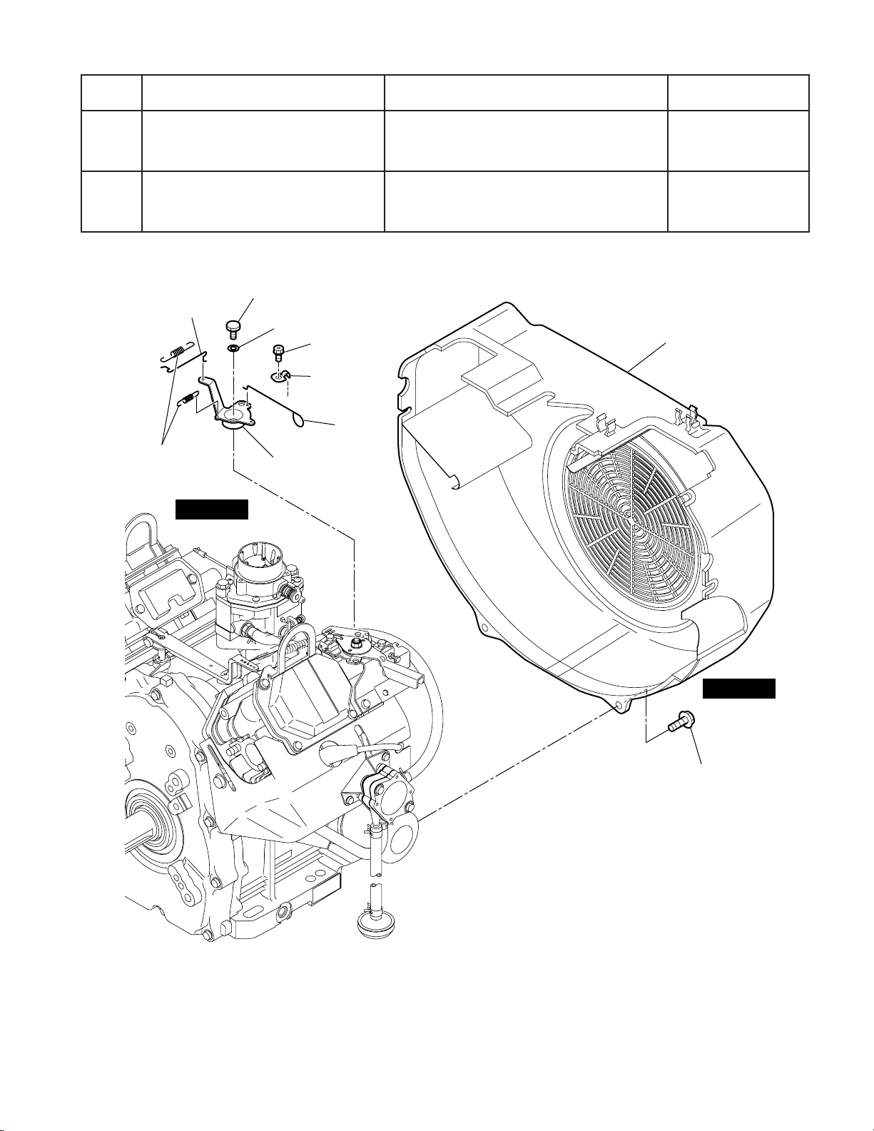
petSevomerotstraPserudecorpdnaskrameRsrenetsaF
4gnisuohrewolB .scp8;21x6M
5knildnarevellortnockcohC 6M
CHOKE
CONTROL ROD
RETURN
SPRING
STEP 5
LINK PIVOT
WAVED
WASHER
CHOKE
CONTROL
LINK
M5 TAPPING
SCREW : 1 pce.
CLAMP
CHOKE
KNOB
BLOWER HOUSING
STEP 4
Fig. 5-5
-
17
M6 FLANGE
BOLT : 8 pcs
-
Page 22
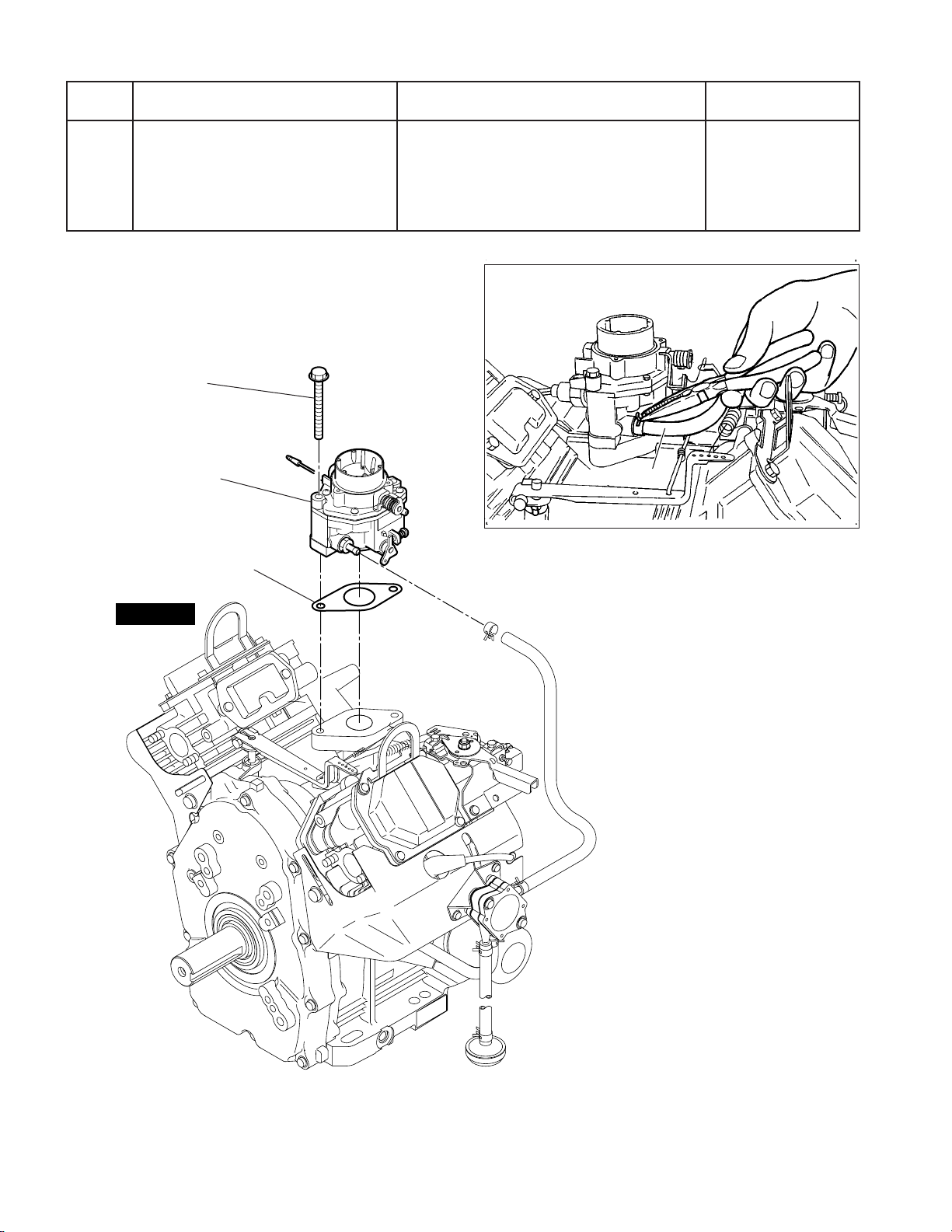
petSevomerotstraPserudecorpdnaskrameRsrenetsaF
6
M8 FLANGE
BOLT : 2 pcs.
CARBURETOR
GASKET, carburetor
roterubraC.epipleufevomertsriftA
.scp2;08x8M
htiwgnolaroterubractuoekaT
.gnirpsdordnadorronrevog
FUEL PIPE
Fig. 5-7
STEP 6
Fig. 5-6
-
18
-
Page 23
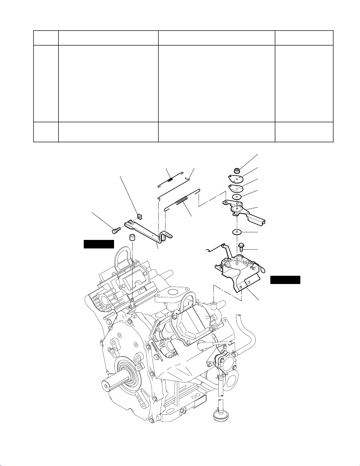
petSevomerotstraPserudecorpdnaskrameRsrenetsaF
;revelronrevoG
.reveltuoekatdnatlobevomeR
;revellortnocdeepS
7
dnarevelronrevoG
revellortnocdeepS
gnirpsronrevoG.1
tunkcolfleS.2
etalppotS.3
rehsawgnirpS.4
revellortnocdeepS.5
8tinutekcarblortnocdeepS Mscp3;21X6
M6 SELF LOCK
NUT : 1 pce.
STOP PLATE
SPRING WASHER
FRICTION
WASHER
SPEED CONTROL
LEVER
FRICTION
WASHER
M6 FLANGE
BOLT : 3 pcs.
M6 NUT : 1 pce.
M6 BOLT
AND WASHER : 1 pce.
STEP 7
ROD
SPRING
GOVERNOR
LEVER
GOVERNOR
ROD
GOVERNOR
SPRING
scp3;21X6M
tunkcol-fles6M
STEP 8
BRACKET UNIT,
speed control
Fig. 5-8
-
19
-
Page 24

petSevomerotstraPserudecorpdnaskrameRsrenetsaF
9pmupleuF.tsriftaepipaesulpevomeRscp2;21x6M
01
SPARK
PLUG CAP
liocnoitingI.pacgulptuoekaT.1
PLUG
TERMINAL
TO STOP DIODE
STEP 10
.lioc
IGNITION
COIL
.liocnoitingievomeR.2
M6 BOLT
AND WASHER
ASSY : 2 pcs.
M&tlob03x6
.scp4;rehsaw
.sdnabgnixiferiwpotstuotuC.3
noitingimorfseriwpotstcennocsiD.4
M6 BOLT
AND WASHER
ASSY : 2 pcs.
IGNITION
COIL
PLUG
TERMINAL
SPARK
PLUG CAP
IGNITION COIL
Fig. 5-10
FIXING BANDS
STEP 9
BRACKET,
fuel pump
HOSE
CLAMP
PULSE
PIPE
Fig. 5-9
M6 FLANGE
BOLT : 2 pcs.
HOSE
CLAMP
FUEL PIPE
M6 FLANGE
BOLT : 2 pcs.
FUEL PUMP
and FUEL
FILTER ASSY
-
20
-
Page 25

petSevomerotstraPserudecorpdnaskrameRsrenetsaF
11
STEP 11
CYLINDER BAFFLE #1
selffabrednilyC
21X6M
)4#&3#,2#,1#(
CYLINDER BAFFLE #3
M6 FLANGE
BOLT : 3 pcs.
M6 FLANGE
BOLT : 2 pcs.
CYLINDER BAFFLE #4
M6 FLANGE
BOLT : 3 pcs.
M6 FLANGE
BOLT : 3 pcs.
Fig. 5-11
CYLINDER BAFFLE #2
-
21
-
Page 26

petSevomerotstraPserudecorpdnaskrameRsrenetsaF
21dlofinamekatnI
31
;tunegnalf8M
.scp4
gulpkrapSSE6RPBroSE6PB:KGN
)CY9NRroCY9N:NOIPMAHCro(
M8 FLANGE
NUT : 2 pcs.
SPARK PLUG
STEP 12
INTAKE MANIFOLD
STEP 13
GASKET, muffler
Fig. 5-12
M8 FLANGE
NUT : 2 pcs.
GASKET, muffler
SPARK PLUG
STEP 13
-
22
-
Page 27

petSevomerotstraPserudecorpdnaskrameRsrenetsaF
ROCKER
SHAFT
ROCKER
COVER
PUSH
ROD
ROCKER
ARM
M8 NUT : 2 pcs.
ADJUSTING
SCREW
GASKET,
rocker cover
CYLINDER
HEAD 1
M6 FLANGE
BOLT : 4 pcs.
M10 FLANGE
BOLT : 4 pcs.
GASKET 1
STEP 14
GASKET 2
CYLINDER
HEAD 2
M10 FLANGE
BOLT : 4 pcs.
GASKET,
rocker cover
M6 FLANGE
BOLT : 4 pcs.
ROCKER
ARM
PUSH
ROD
M8 NUT : 2 pcs.
ADJUSTING
SCREW
ROCKER
COVER
ROCKER
SHAFT
LIFT HOOK
STEP 15
STEP 15
STEP 14
LIFT HOOK
41revocrekcoR .scp4;21x6M
51
dnamrarekcorgnivomernehW
.scp8;56x01M
taleehwylftsujdadnanrut,tfahs
dorhsuPdnadaehrednilyC
tfahsmrarekcoR.1
.daehrednilychcaeno"2"ro
mrarekcoR.2
"1"otdecaf"T"gnikramehthtiwCDT
noitisoplanigirofognikramehttuP
scp2;21X6M
dnamrarekcor,dorhsuphcaeotno
.ylbmessaerrofevlav
-
23
Fig. 5-13
-
Page 28

petSevomerotstraPserudecorpdnaskrameRsrenetsaF
sevlavtsuahxe&ekatnI
61
revocrehtaerB
etalprehtaerB
SPRING
RETAINER
COLLET
-VALVE
VALVE
SPRING
WASHER
STEP 16
SPRING
RETAINER
COLLET
-VALVE
VALVE
SPRING
WASHER
Fig. 5-15
GASKET
BREATHER
GASKET, breather
BREATHER
COVER
INTAKE
VALVE
EXHAUST
VALVE
Fig. 5-14
-
24
-
M6 FLANGE
BOLT : 2 pcs.
Page 29

petSevomerotstraPserudecorpdnaskrameRsrenetsaF
71
81
liocegrahC .scp4;02x5M
STEP 17
M5 BOLT AND
WASHER : 4 pcs.
Fig. 5-17
STEP 18
CHARGE COIL
.rellupgnisuybleehwylftuollupneht
M18 NUT : 1 pce.
SPRING WASHER
WASHER
leehwylFdnatfahsknarcmorfyekevomeR
,rehsaw,tun81M
rehsawgnirps
RING GEAR
Fig. 5-16
FLYWHEEL
Fig. 5-18 Fig. 5-19
-
25
-
Page 30

petSevomerotstraPserudecorpdnaskrameRsrenetsaF
91
WASHER : 2 pcs.
GOVERNOR
GEAR SHAFT
evocgniraebniaM.tfahsOTPmorfyektuoekaT
GOVERNOR GEAR
THRUST BEARING
.scp01;44x8M
epatlynivylophtiwtfahsOTPpaR
evoorgyekyblaeslioegamadotton
.egde
GOVERNOR
SLEEEVE
M8 FLANGE
BOLT : 10 pcs.
STEP 19
GASKET
MAIN BEARING COVER
Fig. 5-20
Fig. 5-21
-
26
-
Page 31

petSevomerotstraPserudecorpdnaskrameRsrenetsaF
teppatdnatfahsmaCnohtobsgnikramehtetaM
raegtfahsmacdnaraegtfahsknarc
02
.tfahsmactuoekatnehtdna
noitisoplanigirofognikramehttuP
.ylbmessaerrofteppathcaeotno
CAMSHAFT
STEP 20
Fig. 5-23
TAPPET
TAPPET
CAMSHAFT
Fig. 5-22
-
27
-
Page 32

petSevomerotstraPserudecorpdnaskrameRsrenetsaF
12
22tfahsknarC
STEP 21
CLIP
pilcnipnotsiP*
nipnotsiP*
sgnirnotsiP*
PISTON PIN
dorgnitcennoCdnanotsiP
PISTON
RING SET
CLIP
CLIP
CONNECTING
ROD CAP
.ylbmessaer
PISTON PIN
CLIP
CONNECTING ROD
.stlobdorgnitcennocevomeR.1
.pacdorgnitcennoctuoekaT.2
.notsiphtiwgnolatuoekatdna
notsip,pilc,gnir,notsiphcaeotno
rofpacdnadorgnitcennoc,nip
PISTON
.scp4;8M
sdrawpudorgnitcennocehthsuP.3
noitisoplanigirofognikramehttuP
PISTON
RING SET
STEP 21
STEP 22
SPACER
CONNECTING
ROD
CONNECTING
ROD CAP
M8 CONNECTING
ROD BOLT : 2 pcs.
CRANKSHAFT
M8 CONNECTING
ROD BOLT : 2 pcs.
Fig. 5-24
-
28
-
Page 33

petSevomerotstraPserudecorpdnaskrameRsrenetsaF
esacknarC
pmupliO*
retlifliO*
32
hctiwserusserpliO*
retlifpmupliO*
llab&gnirpsfeilerliO*
retratscirtcelE*
tfahsrevelronrevoG*
M6 FLANGE
BOLT : 4 pcs.
OUTER
ROTER
INNER
ROTOR
O RING
scp2;56x8M
11x23-01
M8 FLANGE
BOLT : 2 pcs.
BRACKET,
magnetic switch
ELECTRIC
STARTER
GOVERNOR LEVER
SHAFT
STEP 23
SNAP PIN
WASHER
10-32 FLANGE
BOLT (Inch) : 1 pce.
OIL PUMP FILTER
STEEL BALL
SPRING, relief valve
GASKET, aluminum
OIL PUMP COVER
OIL FILTER
OIL PRESSURE
SWITCH
PLUG, oil relief
Fig. 5-25
-
29
-
Page 34

5-4 REASSEMBLY PROCEDURES
5-4-1 PRECAUTIONS FOR REASSEMBLY
1) Clean parts thoroughly before reassembly.
Pay most attention to cleanliness of piston, cylinder, crankshaft, connecting rod and bearings.
2) Scrape off all carbon deposits from cylinder head, piston top and piston ring grooves.
3) Check lip of oil seals. Replace oil seal if the lip is damaged. Apply oil to the lip before reassembly.
4) Replace all the gaskets with new ones.
5) Replace keys, pins, bolts, nuts, etc., if necessary.
6) Torque bolts and nuts to specification referring to the "TORQUE SPECIFICATIONS".
7) Apply oil to rotating and sliding portions.
8) Check and adjust clearances and end plays where specified in this manual.
5-4-2 Pre-assembly
A. CRANKCASE
(1) Fix oil pump filter in position.
(2) Insert ball and spring into the oil relief valve hole and tighten plug to the specified torque.
Tightening Torque : 11.8 - 14.7 N-m (150 - 250 kg-cm, 10.9 - 18.1 ft-lb.)
(3) Fit governor lever shaft with clip.
(4) Tighten oil drain plugs on both side of crankcase.
SNAP PIN
WASHER
OIL DRAIN PLUG
GASKET
OIL FILTER
GOVERNOR LEVER
SHAFT
10-32 FLANGE
BOLT (Inch) : 1 pce.
OIL PUMP FILTER
STEEL BALL
SPRING, relief valve
GASKET, aluminum
PLUG, oil relief
GASKET
OIL DRAIN PLUG
(
ON BOTH SIDE
)
Fig. 5-26
-
30
-
Page 35

B. CYLINDER HEAD, VALVES and ROCKER ARM
NOTE ;
* Clean valves and wash cylinder head thoroughly.
* Remove carbon and gum deposits from the valves, seats, ports and guides.
* Inspect valves, valve seats and valve guides.
* Replace valves that are badly burned, pitted or warped.
* Valve guides should be replaced when valve stem clearance exceeds specifications.
(Refer to SERVICE DATA for clearance specifications. )
If exceeds, draw valve guides out and press new guides in.
After replacing valves and guides, lap valves in place until a uniform ring shows around
the face of the valve.
(1) Attach oil seal only onto intake valve guide.
(2) Apply oil to washer, valve spring and valve stem.
Place cylinder head on flat table and install washer, valve spring, valve and spring retainer.
(3) Install rocker arm and shaft.
Fig. 5-28
ROCKER
ARM
SPRING
RETAINER
COLLET
-VALVE
VALVE
SPRING
WASHER
OIL SEAL
ROCKER
SHAFT
EXHAUST
VALVE
INTAKE
VALVE
Fig. 5-27
-
31
-
Page 36

C. PISTON and CONNECTING ROD
(1) Install oil ring first, then second ring and top ring. Spread ring only far enough to slip over piston and
into correct groove. Use care not to distort ring.
NOTE ;
* Install second ring with punched mark beside the gap on the top side.
* Top ring can be fit either way.
* As for oil ring, rails should be placed on and below the expander.
(2) Apply enough oil to small end of connecting rod and piston pin, and fix connecting rod to piston with
piston pin.
(3) Use clips on the both side of the piston pin to secure piston pin in position.
1
TOP
1
2
RING
BARREL
3
Fig. 5-29
D. Main bearing cover and governor gear
(1) Insert washer into governor gear shaft.
(2) Insert governor gear along with sleeve into
governor gear shaft.
SECOND
2
RING
OIL
3
RING
WASHER : 2 pcs.
GOVERNOR
GEAR SHAFT
TAPER
COMBINATION
RING
GOVERNOR GEAR
GOVERNOR
SLEEEVE
THRUST BEARING
MAIN BEARING COVER
Fig. 5-30
-
32
-
Page 37

5-4-3 Re-assembly
SECOND RING
OIL RING
TOP RING
1) CRANKSHAFT
Install crankshaft onto crankcase.
Note:
Apply enough oil to bearing portion of
crankcase. For easy installation, put
crankcase on box or wood blocks.
CRANKSHAFT
2) PISTON and CONNECTING ROD
(1) Install piston and connecting rod assembly into
cylinder by using a piston ring compressor to
hold piston rings.
Note:
* The "1" mark of the connecting rod for
#1 cylinder and "2" mark for #2 cylinder should be faced to the flywheel side
when assembled.
* Apply enough oil to piston rings, con-
necting rod bearings (large end) and
cylinder bore before assembly.
* Set gaps of piston rings as shown in
the illustration.
(2) Temporary fit key and flywheel and turn crank-
shaft to BTDC (bottom dead center). Lightly
tap the top of piston until large end of the rod
meet the pin portion of crankshaft.
(3) Set connecting rod cap to connecting rod with
the alignment marks mated and the clinching
portion clinched. Tighten bolts to the specified torque.
Fig. 5-31
PISTON RING COMPRESSOR
CONNECTING ROD
1
MARK "1"
Fig. 5-32
ALIGNMENT MARKS
Tightening Torque : 22.1 - 27.0 N-m
(225 - 275 kg-cm)
(16.3 - 19.9 ft-lb.)
(4) Check for free movement of piston and con-
necting rod by turning crankshaft slowly.
-
33
Fig. 5-33
-
Page 38

Page 39

5) MAIN BEARING COVER
(1) Put a oil seal guide onto PTO shaft portion to avoid damaging the main bearing cover oil seal.
(2) Place gasket onto the mating surface of crankcase.
(3) Lubricate oil seal lip potion and bearing surfaces, and install main bearing cover.
Tighten bolts evenly to the specified torque.
Tightening Torque : 16.7 - 18.6 N-m (170 - 190 kg-cm, 12.3 - 13.7 ft-lb.)
NOTE ;
* Before installing main bearing cover, be sure to check the installation of governor lever
shaft and oil pump filter in the crankcase in position.
* Tap cover with a soft hammer until tacthing the crankcase mating surface, engaging
with governor gear and camshaft gear properly.
* Rotate crankshaft slowly to check for smooth operation and side clearance.
6) OIL PUMP and COVER
(1) Apply oil to inner and outer rotors of oil pump
INNER ROTOR
OIL PUMP COVER
and attach them in position.
(2) Set O-ring in position.
(3) Install oil pump cover with the allow marking
upwards.
O-RING
OUTER ROTOR
Fig. 5-37
7) CYLINDER HEAD
NOTE ;
Be sure to check dwell pin, and replace with new one if damaged.
(1) Place new head gasket onto crankcase.
(2) Install #1 and #2 cylinder heads. Tighten bolts evenly in steps to the specified torque;
" "MARKING
Tightening Torque : 33.3 - 41.2 N-m (340 - 420 kg-cm, 24.6 - 30.4 ft-lb.)
8) PUSH ROD
(1) Rotate crankshaft to the position in the no lifted condition of tappet.
(2) Be sure to loose the rocker arm adjust screw.
-
35
-
Page 40

(3) Insert push rods into the concave portion of tappet and set the other end to the concave portion of
THICKNESS
GAUGE
rocker arm adjust screw with valve spring depressed.
(4) Temporally tighten adjust screw.
9) VALVE CLEARANCE ADJUSTMENT
NOTE : Temporally fit the flywheel in position for easy operation.
(1) Rotate crankshaft clockwise to the TDC (top dead center) of compression stroke by matching the
mark "T" of flywheel with the mark "1" of #1 cylinder head.
(2) Loosen lock nut on rocker arm and turn adjusting screw to adjust the clearance between rocker arm
and valve stem end, and then tighten lock nut to the specified torque.
Valve Clearance : 0.085 - 0.115 mm (Cold condition)
Tightening Torque : 9.8 - 13.7 N-m
(100 - 140 kg-cm)
(7.2 - 10.1 ft-lb.)
(3) Adjust valve clearance of #2 cylinder side in
the same manner.
(4) Rotate crankshaft several times and be sure
to check valve clearance again. Adjust valve
clearance if necessary.
Fig. 5-38
#1 CYLINDER#2 CYLINDER
MARK "1"MARK "2"
MARK "T"
FLYWHEEL
Fig. 5-39
-
36
-
Page 41

10) ROCKER COVER
GASKET
BREATHER
GASKET, breather
BREATHER
COVER
M6 FLANGE
BOLT : 2 pcs.
CHARGE COIL
ELECTRIC
STARTER
BLACKET
PULLING
M8 FLANGE
BOLT : 2 pcs.
Install rocker cover with new gasket.
Tightening Torque : 2.9 - 4.9 N-m (30 - 50 kg-cm, 2.2 - 3.6 ft-lb.)
11) BREATHER PIPE and COVER
Attach breather plate (breather valve) and breather
cover to crankcase using proper gaskets.
Put breather plate in such position as its reed
valve opens outside.
Tightening Torque : 2.9 - 4.9 N-m
(30 - 50 kg-cm)
(2.2 - 3.6 ft-lb.)
Note:
Never tighten the bolts over the speci-
fied torque, or gasket is damaged and
cut. Replace gaskets with new ones if
they are torn or damaged.
Fig. 5-40
12) SPARK PLUG
Install spark plug to each cylinder head.
Spark plug : NGK - BP6ES or BPR6ES (CHAMPION - N9YC or RN9YC)
Tightening Torque :
New plug - 11.8 - 14.7 N-m (120 - 150 kg-cm, 8.7 - 10.8 ft-lb.)
Current plug - 22.5 - 26.5 N-m (230 - 270 kg-m, 16.6 - 19.5 ft-lb.)
13) CHARGE COIL
Install charge coil with the wiring located at 2o’clock position.
Tightening Torque : 1.5 - 3.4 N-m
(15 - 35 kg-cm)
(1.1 - 2.5 ft-lb.)
Fig. 5-41
-
37
-
Page 42

14) STARTER MOTOR
INTAKE MANIFOLD
M8 FLANGE NUT : 2 pcs.
GASKET, muffler
GASKET, muffler
M8 FLANGE
NUT : 2 pcs.
THICKNESS GAUGE IGNITION COIL
WIRE
STOP
DIODE
Install starter motor.
Tightening Torque : 16.7 - 18.6 N-m
(170 - 190 kg-cm)
(12.3 - 13.7 ft-lb.)
15) CYLINDER BAFFLE
Attach cylinder baffle #1, #2, #3 and #4.
16) INTAKE MANIFOLD
Set gasket (stainless steel) onto both #1 and #2
cylinder head and install intake manifold.
Tightening Torque : 16.7 - 18.6 N-m
(170 - 190 kg-cm)
(12.3 - 13.7 ft-lb.)
17) FLYWHEEL
(1) Put woodruff key in the keyway of crankshaft.
(2) Wipe off oil and grease thoroughly from
tapered portion of crankshaft and flywheel
center hole.
(3) Install flywheel to crankshaft and tighten
flywheel nut with spring washer and washer.
Tightening Torque : 83.3 - 93.1 N-m
(850 - 950 kg-cm)
(61.5 - 68.7 ft-lb.)
18) IGNITION COIL
Temporally fit ignition coil to crankcase.
Adjust air gap between ignition coil and flywheel
using a thickness gauge and tighten bolts.
Ignition coil air gap : 0.3 - 0.5 mm
(0.012 - 0.020 in.)
Fig. 5-42
Tightening Torque : 6.9 - 8.8 N-m
(70 - 90 kg-cm)
(5.1 - 6.5 ft-lb.)
Connect wiring from stop diode to the primary
terminal of ignition coil.
-
38
Fig. 5-43
-
Page 43

19) CARBURETOR
Set gasket onto intake manifold and install carburetor.
Tightening Torque : 16.7 - 18.6 N-m
(170 - 190 kg-cm)
(12.3 - 13.7 ft-lb.)
20) GOVERNOR LEVER
Attach governor rod and rod spring between
governor lever and carburetor throttle lever, and
insert the governor lever to governor lever shaft.
Tighten locking bolt temporarily.
GOVERNOR SHAFT
GOVERNOR
LEVER
ROD SPRING
GOVERNOR ROD THROTTLE LEVER
Fig. 5-44
-
39
-
Page 44

21) SPEED CONTROL LEVER
Install speed control bracket onto intake manifold.
Attach return spring, spacer, friction washer, wing nut, etc. to speed control lever as shown in the
illustration.
Attach governor spring between governor lever and speed control lever. Attach chock control link
between carburetor chock lever and chock control lever.
CARBURETOR
GOVERNOR GEAR
GOVERNOR LEVER
5
4
3
2
1
SPEED CONTROL
LEVER
GOVERNOR ROD
FULL CLOSE
GOVERNOR SPRING
HIGH SPEED
FULL OPEN
A
B
LOCK NUT
ADJUSTING SCREW
LOW SPEED
Fig. 5-45
-
40
-
Page 45

22) ADJUST GOVERNOR SYSTEM
GOVERNOR LEVER
GOVERNOR SHAFT
(1) Push speed control lever all the way to the
high speed position and fix it by tightening nut.
(2) Check that governor lever is pulled by gover-
nor spring and carburetor throttle valve is fully
open.
(3) Turn governor shaft counterclockwise all the
way and tighten lock bolt to secure the lever
on the shaft.
23) BLOWER HOUSING
Attach blower housing to crankcase.
24) FUEL PUMP
Install fuel pump onto #2 cylinder baffle. Connect
fuel pipe between carburetor and fuel pump.
Fig. 5-46
25) AIR CLEANER
(1) Connect breather pipe to air cleaner base.
(2) Fit air cleaner base onto carburetor.
(3) Connect breather pipe to #1 cylinder head.
(4) Set air cleaner element along with urethane
(5) Install air cleaner cover with knob.
FUEL PUMP
Fig. 5-47
AIR CLEANER BASE
form onto base.
Fig. 5-48
-
41
-
Page 46

26) OIL PRESSURE SWITCH
Install oil pressure switch onto crankcase.
Tightening Torque : 5.9 - 9.8 N-m
(60 - 100 kg-cm)
(4.3 - 7.2 ft-lb.)
27) OIL FILTER
Apply oil to O-ring and install oil filter by tighten-
ing about 3/4 turns after attaching crankcase surface.
Tightening Torque : About 12.3 N-m
(About 125 kg-cm)
(About 9.0 ft-lb.)
OIL PRESURE SWITCH
Fig. 5-49
28) FUEL PUMP PLUSE PIPE
Connect fuel pipe between fuel pump and crank-
case nipple.
29) FINAL CHECK
Be sure to check loosen bolts and nuts, and also
electric wiring connections.
OIL FILTERO-RING
OIL FILTER
3/4 TURNS
Fig. 5-50
-
42
-
Page 47

30) Refill engine oil and start the engine. Engine
UPPER
LEVEL
LOWER
LEVEL
OIL GAUGE
oil will be lubricated oil passages and oil filter.
Check the engine oil level and refill again to the
upper level of oil level gauge.
Note:
*
Total engine oil capacity is about 1.55 L.
* Use "SE" (API classification) or higher
grade engine oil.
Fig. 5-51
5-5 BREAK-IN OPERATION
* An engine that has been completely overhauled by being fitted with a new piston, rings, valves and
connecting rod should be thoroughly RUN-IN before being put back into service. Good bearing surfaces and running clearances between the various parts can only be established by operating the
engine under reduced speed and loads for a short period of time.
* While the engine is being tested, check for oil leaks.
* Make final carburetor adjustment and regulate the engine operating speed.
petS
D36HED46HED56HE
1petS daoLoNmpr005,2.nim01
2petS daoLoNmpr000,3.nim01
3petS daoLoNmpr006,3.nim01
4petS PH3.7PH8PH5.8mpr006,3.nim03
5petS PH5.41PH61PH71mpr006,3.nim03
daoL
deepSenignEemiT
Table. 5-1
-
43
-
Page 48

6. MAGNETO
6-1 OPERATION AND FUNCTION
The ignition system is pointless flywheel magneto with automatic advancing characteristic.
Being different from the breaker point type ignition system, this system is completely free from such
troubles as starting-up failure owing to dirty, burnt or corroded point surface.
The electronic automatic advancing ensures extremely easy starts and stable high performance at oper-
ating speed by advancing the ignition timing to the most suitable point.
Low Speed
Ignition
Timing
Control Circuit
Resister
I1
I3
Power Transistor
Primary Coil
Automatic
Advancing
Control
Circuit
Signal Transistor A
I4
I5
I2
Signal Transistor B
Secondary Coil
Spark plug
I6
Fig. 6-1 (a)
ELECTRONIC ADVANCING FLYWHEEL
(
B.T.D.C.
)
MAGNETO SYSTEM
STEP ADVANCING
IGNITION TIMING
500 1000 2000 3000 (r.p.m.)
ENGINE REVOLUTION
Fig. 6-1 (b)
* BASIC THEORY
(1) Revolution of the flywheel generates electricity on the primary side of the ignition coil, and the base
current I1 flows to the power transistor. Current I1 turns the power transistor "ON" and the electric
current I2 flows.
-
44
-
Page 49

(2) At lower engine revolution, when the flywheel reached the ignition point the low speed ignition timing
control circuit operates to run the base current I3 to turn the signal transistor A "ON" allowing the
current /1 to bypass as current I4.
At this moment the power transistor turns "OFF" and the current I2 is abruptly shut resulting in the
high voltage generated in the secondary coil which produces sparks at the spark plug.
(3) At higher engine revolution, the advancing control circuit operates at the ignition timing to run the
base current I5 to turn the signal transistor B "ON" allowing the current I1 to bypass as current I6.
At this moment the power transistor turns "OFF" and the current I2 is abruptly shut resulting in the
high voltage generated in the secondary coil which produces sparks at the spark plug.
The operating timing of the advancing control circuit advances in accordance with the increase of
engine speed resulting in the advancing of ignition timing.
* WIRING DIAGRAM
Connect key switch, magnetic switch and battery with wirings of proper gauge as shown by the dotted
lines in the wiring diagram.
OIL PRES.
SWITCH
CARBURETOR
IGNITION
COIL
CHARGE
COIL
BLACK
BLACK
RED
STOP
DIODE
TO TACH.
/HOUR METER
DIODE
RECTIFIER
BLACK BLACK
BROWN
GREEN
ELECTRIC
STARTER
KEY SWITCH
RED
WHITE
LA406
LA406
OFF
ON
BLUE
KEY
SWITCH
M
S
B
L
G
LA106
LA406
MAGNETIC
SWITCH
GMBLS
BLUE
YELLOW
+
BATTERY
12V-30AH
-
GRAY
LAMP
Fig. 6-2
-
45
START
-
Page 50

7. LUBRICATION SYSTEM
7-1 OPERATION AND FUNCTION
* Full lubrication system is adopted, in combination with large-size torchoid oil pump and cartridge type
oil filter.
* The large-size trochoid type oil pump is driven directly by crankshaft, and delivers pressurized engine
oil to the journal and pin portions of crankshaft, camshaft etc.
* The engine oil in the oil pan is fed trough the oil pump filter into oil pump and the engine oil pressure is
adjusted by the relief valve after discharging from oil pump. Through the cartridge type oil filter, the
engine oil is provided onto the rotating portions such as journal and pin portion of crankshaft and
camshaft. The splashed engine oil is provided to the cylinder, piston, cylinder head valve system.
* The by-pass valve is incorporated into the cartridge type oil filter. In case that the oil filter element is
clogged, the engine oil is fed through the by-pass valve into the crankcase oil passage.
OIL FILTER
RELIEF VALVE
CAMSHAFT
CRANKSHAFT
OIL PUMP
Fig. 7-1
-
46
OIL PUMP FILTER
-
Page 51

8. CARBURETOR
AIR
AIR VENT HOLE
CHOKE VALVE
PILOT AIR JET
MAIN AIR JET
FLOAT
NEEDLE VALVE
FUEL INLET PIPE
FUEL
MAIN NOZZLE
THROTTLE VALVE
BY-PASS
PILOT OUTLET
MIXTURE
TAMPER CAP
EMULSION TUBE
FUEL CUT VALVE
MAIN JET
PILOT JET
8-1 OPERATION AND FUNCTION
Fig. 8-1
-
47
-
Page 52

8-1-1 FLOAT SYSTEM
The float system is consists of a float and a needle valve, and maintains a constant fuel level during
engine operation.
The fuel flows from the fuel tank into the float chamber through needle valve.
When the fuel rises to a specific level, the float rises, and when its buoyancy and fuel pressure are
balanced, the needle valve closes to shut off the fuel, thereby keeping the fuel at the predetermined
level.
Air vent hole of float chamber is provided around the carburetor air hone and the fuel vapor is sucked into
the combustion chamber. This closed system has unti-dust feature.
8-1-2 PILOT SYSTEM
The pilot system feeds the fuel to the engine during idling and low-speed operation.
The fuel is fed through the main jet to the pilot jet, where it is metered, and mixed with the air metered by
the pilot air jet.
The fuel-air mixture is fed to the engine through the pilot outlet and the by-pass.
At idling speed, the fuel is mainly fed from the pilot outlet.
8-1-3 MAIN SYSTEM
The main system feeds the fuel to the engine at medium-and high-speed operation.
The fuel is metered by the main jet and fed to the main nozzle. The air metered by the main air jet is
mixed with the fuel through the emulsion tube, and the mixture is atomized out of the main bore. It is
mixed again with the air taken through the air cleaner into an optimum fuel-air mixture, which is supplied
to the engine.
8-1-4 CHOKE
The choke is used for easy start when engine is cold.
When the starter is operated with a choke valve fully closed, the negative pressure applied to the main
nozzle increases and draws much fuel accordingly; thus easily start up the engine.
8-1-5 FUEL CUT VALVE
Fuel cut valve, operated with starter key switch, is equipped with main system of carburetor for prevent-
ing engine running on and after burning.
When the key switch is on, the valve is activated and the plunger is pulled in to open the main jet.
When the key switch is off, the power source to the valve is off. The plunger is pushed out by the return
spring and stop the fuel flow of main jet.
-
48
-
Page 53

8-2 COMPORNENT PARTS
19
3
4
5
6
2
7
9
8
10
1. BODY, lower
12
11
11. MAIN JET
13
1
Fig. 8-2
15
16
14
18
17
20
2. GASKET, body upper
3. BODY, upper
4. LEVER ASSY, choke
5. SPRING, choke
6. SHAFT ASSY, choke
7. CHOKE VALVE
8. VALVE, float
9. FLOAT ASSY
10. FLOAT PIN
12. SOLENOID VALVE ASS’Y
13. JET, slow
14. NEEDLE, idle adjust
15. THROTTLE SHAFT ASS’Y
16. THROTTLE VALVE
17. EXPANSION PLUG
18. PLUG
19. O-RING
20. PLUG, anti tamper
-
49
-
Page 54

Page 55

9-2 COMPORNENT PARTS
THROUGH BOLT (2 pcs.)
BRUSH HOLDER
ARMATURE
BRUSH (4 pcs.)
YOKE ASSEMBLY
FRONT COVER
PINION ASSEMBLY
PINION RETURN
SPRING
PINION STOPPER
PINION STOPPER
CLIP
SPACER
GUIDE PLATE
Fig. 9-3
-
51
-
Page 56

10. TROUBLESHOOTING
The following three conditions must be fulfilled for satisfactory engine start.
(1) The cylinder filled with a proper fuel-air mixture.
(2) Good compression in the cylinder.
(3) Good spark, properly timed, to ignite the mixture.
The engine cannot be started unless these three conditions are met.
There are also other factors which make engine start difficult, e.g., a heavy load on the engine when it
is about to start at low speed, and a high back pressure due to a long exhaust pipe.
The most common causes of engine troubles are given below:
10-1 NO ENGINE OPERATION
nonemonehPsesuacelbissoPydemeR
gniriwhctiwsyekfonoitcennocrooP)1 ecalperroriaper,kcehC
retratsdnahctiwsyekneewtebytiunitnocsidgniriW)2
rotom
retratsdnayrettabneewtebytiunitnocsidgniriW)3
rotom
.1
retratscirtcelE
tonseod
.etarepo
.2
retratscirtcelE
tub,setarepo
seodenigne
.tratston
yrettab
lanimretyrettabfonoitcennocrooP)5 ecalperronaelc,kcehC
ytluafhctiwscitengamretratS)6 ecalperroriaper,naelc,kcehC
ytluafrotomretratS)7 ecalperroriapeR
eruziestfahsknarC)8 ecalperroriaper,kcehC
rednilycdnanotsipneewteberuzieS)9 ecalperroriaper,kcehC
leufoN)1llifeR
sgniriw
ytluafretratscirtcelE)3 ecalperroriapeR
degrahcsidro)yticapacwol(yrettabreporpmI)4
metsysnoitingifoytiunitnocsidronoitcennocrooP)2
ecalpeR
ecalpeR
yrettabecalperroegrahC
ecalperroriaper,kcehC
-
52
-
Page 57

10-2 STARTING DIFFICULTIES
nonemonehPsesuacelbissoPydemeR
enignewoL.1
tadeeps
gnitrats
degrahcsidyrettaB)1yrettabegrahC
rotomretratsdnayrettabneewtebnoitcennocrooP)2riaperronaelC
dnuorgdnayrettabneewtebnoitcennocrooP)3riaperronaelC
ytluafretratscirtcelE)4 ecalperroriapeR
lioenignereporpmI)5
gulpkrapS
paggulpkrapsreporpmI*
noitalusnioN*
noitingI.2
metsys
noitcnuflam
metsysleuF.3
noitcnuflam
liocnoitingI
wolfrevO*
stisopednobraC*
ytiunitnocsidronoitalusnioN*
edocnoitingifoytiunitnocsidronoitcennocrooP*
leehwylfdnaliocnoitingineewtebpagriareporpmItsujdA
knatleufnileufoN)1llifeR
deggolcpmupleuF)2naelC
dehcniprodeggolcesohleuF)3 ecalperronaelC
senilleufotnigniximriA)4
noitartlifniretawroenilosagreporpmI)5ecalpeR
roterubraC)6
degamadrodeggolC*
evlavelttorhtfonoitareporeporpmI*
lioenigne
tsujdA
ecalpeR
naelC
ecalpeR
ecalperroriapeR
noitrop
tsujdA
tsujdadnakcehC
dednemmocerhtiwecalpeR
gnitcennoctsujdadnakcehC
naelcdnaylbmessasiD
gniriwevlavtucleuffonoitcennocrooP)7 riaperdnakcehC
stlobdaehrednilycfogninethgittneiciffusnI)1 nethgiterdnakcehC
rednilycro/dnagnirnotsip,notsipforaeW)2 ecalperroriapeR
taesdnaevlavfotcatnocreporpmI)3riapeR
erocenignE.4
stnenopmoc
noitcnuflam
eruziesevlaV)4riapeR
ecnaraelcevlavreporpmI)5tsujdA
egakaelteksagdlofinamekatnI)6
egakaelteksagroterubraC)7
gulpkrapsfogninethgittneiciffusnI)8nethgiteR
-
53
-
rostlobdlofinamekatninethgiteR
teksagecalper
rostlobroterubracnethgiteR
teksagecalper
Page 58

10-3. INSUFFICIENT OUTPUT
nonemonehPsesuacelbissoPydemeR
woL.1
noisserpmoc
gulpkrapsnesooL)1 teksagecalperronethgiteR
egakaelteksagdaehrednilyC)2 teksagecalperronethgiteR
raewroeruzies)s(gnirnotsiP)3ecalpeR
raewrednilycronotsiP)4 ecalperroriapeR
tcatnoctaesdnaevlavtcerrocnI)5 ecalperroriapeR
eruziesmetsevlaV)6 ecalperroriapeR
ecnaraelcevlavreporpmI)7tsujdA
ytluafgulpkrapS)1ecalpeR
noitingI.2
metsys
noitcnuflam
metsysleuF.3
noitcnuflam
ekatniwoL.4
emulovria
10-4. OVERHEAT
ytluafliocnoitingI)2ecalpeR
leehwylfdnaliocnoitingineewtebpagriareporpmI)3tsujdA
noitazitengamedotengaM)4ecalpeR
deggolcroterubraC)1 naelcdnaylbmessasiD
noitarepopmupleufreporpmI)2 naelcdnaylbmessasiD
deggolcesohleufroreniartsleuF)3 ecalperronaelC
senilleufotnigniximriA)4
noitartlifniretawroenilosagreporpmI)5ecalpeR
deggolcrenaelcriA)1 ecalperronaelC
ytluafevlavelttorhT)2 ecalperroriapeR
gnitcennoctsujdadnakcehC
noitrop
nonemonehPsesuacelbissoPydemeR
elffabrednilycrotelnitadetcurtsbowolfriagnilooC)1
noitrop
lioenignereporpmI)2ecalpeR
gnitaehrevO
daol-revO)5 daoldetarotegnahC
erutximleuf/rianaeL)3 roterubractsujdadnakcehC
metsystsuahxefoerusserpkcabevissecxE)4 ecalperronaelc,kcehC
-
54
-
naelC
Page 59

10-5. ROUGH IDLING
nonemonehPsesuacelbissoPydemeR
roterubraC.1
deepsgnildiwoL)1tsujdA
deggolcegassapmetsyswolsroterubraC)2 naelcdnakcehC
ekatnI.2
metsys
rednilyC.3
daeh
metsysevlaV.4
noitingI.5
metsys
metsys
ecnaraelcevlavreporpmI)1tsujdA
taesevlavmorfegakaeL)2 tcatnoctaesevlavtsujdA
krapsnoitingikaeW)1 gulpkrapsecalperdnakcehC
10-6. HIGH ENGINE OIL CONSUMPTION
nonemonehPsesuacelbissoPydemeR
gulpniardnesooL)1nethgiT
gnittifretlifliotcerrocnI)3riapeR
egakaelliO.1
ekatniriafonoitropgnitcennocmorfgniximriA)1
)yb-wolb(ytluafteksagdaehrednilyC)1ecalpeR
ediugdnametsevlavneewtebecnaraelcevissecxE)3ecalpeR
degamadteksaggulpniarD)2ecalpeR
stlobrevocgniraebniamnesooL)4nethgiT
teksagecalperronethgit,kcehC
degamadteksagrevocgniraebniaM)5ecalpeR
degamadlaesliotfahsknarC)6ecalpeR
ytluafgnirlionotsiP)1ecalpeR
tcatnocrooproraew,eruziessgnirnotsiP)2ecalpeR
rednilycdnanotsipforaewevissecxE)3ecalpeR
noitulidliO.2
metsevlavforaewevissecxE)4ecalpeR
levelliohgiH)5levelliotsujdA
ytluafrehtaerB)6 ecalperroriapeR
-
55
-
Page 60

10-7. HIGH FUEL CONSUMPTION
nonemonehPsesuacelbissoPydemeR
tejniamezis-revO)1ecalpeR
metsysleuF.1
erocenignE.2
stnenopmoc
10-8. DETONATION
nonemonehPsesuacelbissoPydemeR
noitingI.1
metsys
noitcnuflam
metsysleuF.2
noitcnuflam
taolfnilevelleufhgihro/dnaytluafevlaveldeeN)2
rebmahc
.yllufnepotonseodevlavkcohC)3 ecalperroriapeR
noisserpmocwoL)1 riaperrokcehC
gniloocrevO)2
sgniriwmetsysnoitingifonoitcennocrooP)1 ylreporptcennocdnakcehC
gulpkrapsdegamadroreporpmI)2 ecalperronaelC
erutximleuf/riahcirronaeL)1 ecalperrotsujda,naelC
degamadroterubraC)2 naelcdnaylbmessasiD
degamadrodeggolcsenilleuF)3 ecalperronaelC
ecalperrotsujdA
ro/dnadaoltsujdadnakcehC
deepsenigne
ekatniriafonoitropgnitcennocmorfgniximriA)4
metsys
rednilyC.3
daeh
ecnaraelcevlavreporpmI)1tsujdA
noitaroiretedtaehevlaV)2ecalpeR
metsysevlaV.4
noitaroiretedgnirpsevlaV)3ecalpeR
gnimitevlavreporpmI)4tsujdA
rebmahcnoitsubmocnitisopednobraC)1 naelcdnaevomeR
)yb-wolb(ytluafteksagdaehrednilyC)2ecalpeR
teksag
ecalperroylreporptcennoC
-
56
-
Page 61

10-9. ENGINE MISFIRE
nonemonehPsesuacelbissoPydemeR
edortceledegamadropaggulpkrapsrepprpmI)1 ecalperrotsujda,naelC
noitingI.1
metsys
metsysleuF.2
tnemtsujda
erocenignE.3
stnenopmoc
ytluafliocnoitingi)2ecalpeR
sgniriwmetsysnoitingidegamaD)3ecalpeR
sgniriwmetsysnoitingifonoitcennocrooP)4 ylreporptcennocdnakcehC
erutximleuf/riahcirronaeL)1 riaperdnaylbmessasiD
deggolcroterubraC)2 riaperdnaylbmessasiD
roterubracfotnemtsujdagnildireporpmI)3tsujdA
noitartlifniretawroenilosagreporpmI)4ecalpeR
evlavreporpmironoitaroiretedtaehevlaV)1
noitaroiretedgnirpsevlaV)2ecalpeR
noisserpmocwoL)3 ecalperrotsujda,kcehC
ecalperrotsujdA
-
57
-
Page 62

11. INSTALLATION
Engine life, ease of maintenance and inspection, frequency of checks and repairs, and operating cost all depend on
the way in which the engine is installed. Review the following instructions carefully for installing the engine.
11-1 INSTALLING
When mounting the engine, carefully examine its position, the method of connecting it to a machine, the foundation,
and the method of supporting the engine.
When determining its mounting position, in particular, make sure that gasoline and oil can easily be supplied and
checked, the spark plug can easily be checked, the air cleaner can easily be serviced, and that the oil can easily be
discharged.
11-2 VENTILATION
Fresh air is necessary for cooling the engine and burning the fuel.
In the case the engine is operated under a hood or in a small room, temperature rise in the engine room can cause
vapor lock, oil deterioration, increased oil consumption, loss of power, piston seizure, shorter engine life, etc.,
making it impossible to operate the engine properly. It is necessary, therefore, to provide a duct or baffle to guide
cooling air to the engine to prevent recirculation of he hot air used for engine cooling, and temperature rise of the
machine.
Keep the engine room temperature below 50 °C even in the hottest period of the year.
11-3 EXHAUST GAS DISCHARGE
Exhaust gas is noxious. When operating the engine indoors, be sure to discharge the exhaust gas outdoors. If a
long exhaust pipe is used in such a case, the internal resistance increases causing loss of engine power. Thus pipe
inside diameter must be increased in proportion to exhaust pipe length.
Exhaust pipe : Less than 3 m long --- pipe inside diameter 30 mm
Less than 5m long --- pipe inside diameter 33 mm.
11-4 POWER TRANSMISSION TO DRIVEN MACHINES
11-4-1 BELT DRIVE
Take the following notes into consideration.
* V-belts are preferable to flat belts.
* The driving shaft of the engine must be parallel to the driven shaft of the machine.
* The driving pulley of the engine must be in line with the driven pulley of the machine.
* Install the engine pulley as close to the engine as possible.
* If possible, span the belt horizontally.
* Disengage the load when starting the engine.
If no clutch is used, use a belt tension pulley or the like.
11-4-2 FLEXIBLE COUPLING
When using a flexible coupling, run out and misalignment between the driven shaft and engine shaft must be
minimized. Run out and misalignment tolerance are specified by the coupling manufacturer.
-
58
-
Page 63

12. SERVICE DATA
12-1 CLEARANCE DATA AND LIMITS
METI
DAEHREDNILYC
ssentalF*
Unit : mm (in)
D56/D46/D36HE
DTStimiL
sselro50.0
)sselro200.0(
htdiwtcatnoctaesevlaV*
.XE.NI
.aidedisniediugevlaV*
0.1-7.0
)930.0-820.0(
350.6-530.6
)3832.0-6732.0(
1.0
)400.0(
0.2
)970.0(
51.6
)242.0(
-
59
-
Page 64

Unit : mm (in)
D56/D46/D36HE
METI
DTStimiL
REDNILYC
.aidedisnI*
DTS
910.08-000.08
)4051.3-6941.3(
.)400.0(1.0
nehwderobereboT
neewtebecnereffideht
fo.nimdna.xam
otdehcaerretemaid
ts1
gnirober
ts2
gnirober
.gniroberretfassenidnuoR*
.gniroberretfayticirdnilyC*
NOTSIP
)noitceridtsurhtnitrikstA(ezisnotsiP*
DTS
962.08-052.08
)061.3-951.3(
915.08-005.08
)071.3-961.3(
10.0
)400.0(
510.0
)6000.0(
889.97-869.97
)941.3-841.3(
ottiD
------------
------------
------------
878.97
)541.3(
16 mm
s/ots1
s/odn2
-
60
-
832.08-812.08
)951.3-851.3(
884.08-864.08
)961.3-861.3(
821.08
)551.3(
873.08
)461.3(
Page 65

Unit : mm (in)
D56/D46/D36HE
METI
DTStimiL
NOTSIP
ecnaraelcedisevoorggniR*
elohnipnotsiP*
.aidedistuonipnotsiP*
poT
dn2
gnirliO
90.0-50.0
)5300.0-2000.0(
70.0-30.0
)8200.0-2100.0(
571.0-750.0
)9600.0-2200.0(
200.12-989.02
)9628.0-3628.0(
000.12-199.02
)8628.0-4628.0(
51.0
)600.0(
51.0
)600.0(
51.0
)600.0(
530.12
)1828.0(
069.02
)1528.0(
trikstarednilycdnanotsipneewtebecnaraelC*
.aera
150.0-210.0
)0200.0-5000.0(
pagdnegnirnotsiP*
poT
dn2
gnirliO
4.0-2.0
)7510.0-9700.0(
7.0-2.0
)6720.0-9700.0(
52.0
)8900.0(
5.1
)1950.0(
5.1
)1950.0(
-
61
-
Page 66

Page 67

Unit : mm (in)
D56/D46/D36HE
METI
DTStimiL
TFAHSMAC
).XEdna.NI(thgiehmaC*
3.63-1.63
)1924.1-3124.1(
.aidedistuolanruoJ*
epyt"D"
DD
089.91-769.91
)6687.0-1687.0(
EVLAV
.aidedistuometsevlaV*
.NI
.XE
589.5-079.5
)6532.0-0532.0(
579.5-069.5
)2532.0-6432.0(
59.53
)4514.1(
059.91
)4587.0(
58.5
)3032.0(
58.5
)3032.0(
evlavdna.aidmetsevlavneewtebecnaraelC*
.ediug
.NI
.XE
ecnaraelcevlaV*
.XE/.NI
)dloc(
-
63
-
380.0-050.0
)3300.0-2200.0(
390.0-060.0
)7300.0-4200.0(
511.0-580.0
03.0
)8110.0(
03.0
)8110.0(
)5400.0-4300.0(
Page 68

Unit : mm (in)
D56/D46/D36HE
METI
DTStimiL
TEPPAT
.aidedistuometS*
579.8-069.8
)3353.0-8253.0(
.aidedisniediuG*
39.8
)6153.0(
510.9-00.9
)9453.0-3453.0(
ecnaraelcediugteppaT*
550.0-520.0
)2200.0-0100.0(
MRAREKCOR
.aidedistuotfahsrekcoR*
499.11-689.11
)2274.0-9174.0(
.aidelohmrarekcoR*
420.21-600.21
)4374.0-7274.0(
80.9
)5753.0(
51.0
)9500.0(
29.11
)3964.0(
70.21
)2574.0(
ecnaraelctfahsmrarekcoR*
830.0-210.0
)5100.0-5000.0(
HTGNELEERFGNIRPSEVLAV
5.93
)1555.1(
-
64
-
51.0
)9500.0(
------------
Page 69

Page 70

12-3 OIL GRADE CHART
Use oil classified as SE or higher.
Multi-grade oil tends to increase its consumption at high ambient temperature.
Comparison between oil viscosity and temparature
5W
10W
Specified
Lubricant
Quality
Single
grade
Multigrade
-
-
20
4
-
10
14
32
20W
#20
#30
#40
10W-30
10W-40
0
10
50
20
68
30
86
40 °C
104 °F
-
66
-
Page 71

13. MAINTENANCE AND STORAGE
13-1 DAILY MAINTENANCE
Every day before operating engine, check the following items;
SMETIECNANETNIAMSKRAMER
.enignemorfffahcdnatsudyawanaelC)1 .tsudotevitisnesyllaicepsesiegaknilronrevoG
,ynafI.metsysleufmorfegakaelleufkcehC)2
.strapyrassecenecalperrosrenetsafnethgiter
finethgiterdnaerawdrahesoolroftcepsnI)3
.yrassecen
.levelllufotddadnalevelliokcehC)4
13-2 PERIODIC MAINTENANCE SCHEDULE
Periodic maintenance is vital to safe and efficient operation of engine.
Check the table below for periodic maintenance intervals.
nitluserdnaffoemocyamstundnastlobesooL
.straprehtofoegakaerb
It is also necessary to conduct the maintenance and adjustments on the emission-related parts listed
below to keep the emission control system effective;
(1) Carburetor and internal parts (2) Choke system
(3) Fuel strainer (4) Air cleaner elements
(5) Intake pipe (6) Spark plug
(7) Magneto (8) Fuel hoses, clamps and sealing gaskets
The following maintenance schedule is based on the normal engine operation.
Should the engine be operated in extremely dusty condition or in heavier loading condition, the mainte-
nance interval must be shortened depending on the contamination of oil, clogging of filter elements, wear
of parts, and so on.
-
67
-
Page 72

yrevE
smetIecnanetniaM
stundnastlobkcehcdnaenignenaelC )yliaD(X
X llifeR(
lioenignelliferdnakcehC
lioenigneegnahC )1etoN*( X
leveldiulfetylortceleyrettabkcehC X
gulpkrapsnaelCX
renaelcrianaelCX
reniartsleufnaelC X
tnemelerenaelcriaecalpeR X
sedortcelednagulpkrapstsujdadnanaelC X
)1etoN*(retliflioenigneecalpeR X
sruoh8
)yliad(
otyliad
).levellluf
yrevE
05
sruoh
yrevE
002
sruoh
yrevE
005
sruoh
yrevE
000,1
sruoh
roterubracnaelC X
daehrednilycnaelC X
)naplio(esabenignenaelC X
staeselavtsujdadnakcehC X
ecnaraelcevlavtsujdA X
gulpkrapsecalpeR X
senilleufecalpeR X
enigneluahrevO )2etoN*( X
*Note 1 : Initial oil change and oil filter replacement should be performed after 20 hours of operation.
Thereafter change oil every 50 hours and replace oil filter every 200 hours.
Before changing oil, check for a suitable way to dispose of old oil. Do not pour it down into
sewage drains, onto garden soil or into open streams. Your local zoning or environmental
regulations will give you more detailed instructions on proper disposal.
2 : As to the procedures, please refer to the Service Manual or consult your nearest ROBIN
service dealer.
-
68
-
Page 73

13-3 ENGINE STORAGE
(1) Change the engine oil and perform the daily maintenance items above mentioned.
(2) Drain fuel from carburetor float chamber.
(3) To prevent rust in the cylinder bore, apply oil through the spark plug hole and turn the crankshaft
several turns by hand. Reinstall the plug.
(4) Turn the crankshaft by hand and leave it where the resistance is the heaviest.
(5) Clean outside of the engine with oiled cloth.
(6) Put a plastic cover or the like over the engine and store the engine in dry place.
-
69
-
Page 74

PRINTED IN THE USA
 Loading...