

Page 1
ISSUE EMD-PU1692
9ZZ9990018
Page 2
Page 3
Page 4
Company
Page 5
PKV101
PKV101
102
February 27. 2003
27. Februar 2003
27. février 2003
27. februari 2003
27. febbraio 2003
27. 2003
27. febrero 2003
27. Fevereiro 2003
27. februari 2003
27. helmikuu 2003
27. februar 2003
27. februar 2003
1784
Page 6
FOREWORD
SER No.
Thank you very much for purchasing a ROBIN PUMP.
This manual covers operation and maintenance of ROBIN PUMP.
All information in this publication is based on the latest product information available at the
time of approval for printing. Please read this manual carefully before operating.
Please take a moment to familiarize yourself with the proper operation and maintenance
procedures in order to maximize the safe and efficient use of this product.
Keep this owner’s manual at hand, so that you can refer to it at any time.
Due to constant efforts to improve our products, certain procedures and specifications are
subjected to change without notice.
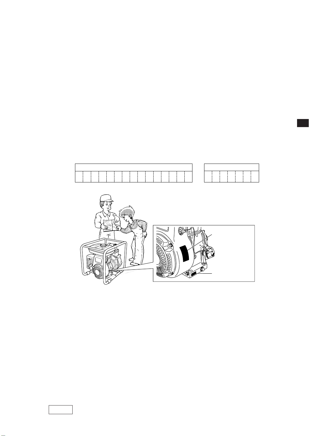
When ordering spare parts, always give us the MODEL, PRODUCTION NUMBER and SERIAL
NUMBER of your pump.
Please fill in the following blanks after checking the production number on your pump.
(Location of label is different depending on the pump specification.)
PROD No.
GB
PROD No. / SER No.
(
)
Label
SER No.
(
Stamping
)
CONTENTS
Page
1. SAFETY PRECAUTIONS................................................................................... 2
2. COMPONENTS.................................................................................................. 4
3. PRE-OPERATION FOR STARTING .................................................................. 6
4. OPERA TING YOUR PUMP................................................................................ 7
5. MAINTENANCE ................................................................................................. 7
6. PREPARATIONS FOR STORAGE..................................................................... 10
7. OIL SENSOR INSTRUCTIONS (OPTIONAL)
.....................................................
8. EASY TROUBLESHOOTING............................................................................. 11
9. SPECIFICATIONS.............................................................................................. 12
10
NOTE Please refer to the illustrations on the back page of the front
cover or back cover for Fig.
1 1
1 to
1 1
ii
i indicated in the sentence.
ii
1
Page 7

1. SAFETY PRECAUTIONS
1m
1m
Please make sure you review each precaution carefully.
Pay special attention to statement preceded by the following words.
GB
WARNING
“WARNING” indicates a strong possibility of severe personal injury or loss of life if
instructions are not followed.
CAUTION
“CAUTION” indicates a possibility of personal injury or equipment damage if instructions
are not followed.
WARNING
■
Never inhale exhaust gasses.
They contain carbon monoxide, a colorless, odorless and extremely dangerous gas
which can cause unconsciousness or death.
■
Never operate the pump indoors or in a poorly ventilated area, such as tunnel, cave,
etc.
■
Exercise extreme care when operating the pump near people or animals.
■
Keep the exhaust pipe free of foreign objects.
WARNING
■
Gasoline is extremely flammable and its vapors can explode if ignited.
■
Do not refuel indoors or in a poorly ventilated area.
■
Be sure to stop the pump prior to refueling.
■
Do not remove fuel tank cap nor fill fuel tank while engine is hot or running.
Allow engine to cool at least 2 minutes before refueling.
■
Do not overfill the fuel tank.
■
If fuel is spilt, wipe it away carefully and wait until the fuel has dried before starting the
engine.
■
After refueling, make sure that the fuel cap is secured to prevent spillage.
: EXHAUST PRECAUTIONS
: REFUELING PRECAUTIONS
WARNING
■
Do not operate the pump while smoking or near an open flame.
■
Do not use around dry brush, twigs, cloth rags, or other flammable materials.
■
Keep cooling air intake (recoil starter area) and muffler side of the engine at least
: FIRE PREVENTION
1 meter (3 feet) away from buildings, obstructions and other burnable objects.
■
Keep the pump away from flammables and other hazardous materials (trash, rags,
lubricants, explosives).
WARNING
■
Be careful of hot parts.
: OTHER SAFETY PRECAUTIONS
The muffler and other engine parts become very hot while the pump is running or just
after it has stopped. Operate the pump in a safe area and keep children away from
the running pump.
■
Do not use diaphram pump for the mixture of water and oil.
2
Page 8

■
Do not touch the spark plug and ignition cable when starting and operating the engine.
■
Operate the pump on a stable, level surface.
If the engine is tilted, fuel spillage may result.
NOTE
Operating the pump at a steep incline may cause seizure due to improper lubrication
even with a maximum oil level.
■
Do not transport the pump with fuel in tank or with fuel strainer cock open.
■
Keep the unit dry (do not operate it in rainy conditions).
GB
CAUTION
■
Carefully check fuel hoses and joints for looseness and fuel leakage. Leaked fuel
: PRE-OPERATION CHECKS
creates a potentially dangerous situation.
■
Check bolts and nuts for looseness. A loose bolt or nut may cause serious engine
trouble.
■
Check the engine oil and refill if necessary.
■
Check the fuel level and refill if necessary. Take care not to overfill the tank.
■
Keep cylinder fins and recoil starter free of dirt, grass and other debris.
■
Wear snug fitting working clothes when operating the engine.
Loose aprons, towels, belt, etc., may be caught in the engine or drive train, causing a
dangerous situation.
3
Page 9

SYMBOLS
Read the owner's manual.
Stay clear of the hot surface.
Exhaust gas is poisonous.
Do not operate in an unventilated area.
GB
Stop the engine before refueling.
Fire, open flame and smoking prohibited.
On (Run) Plus ; Positive polarity
Off (Stop) Battery
Engine oil
Add oil
Engine start
(Electric start)
2. COMPONENTS
(See Fig.
NOTE Please refer to the illustrations on the back page of the front
11
1)
11
cover or back cover for Fig.
1 1
1 to
1 1
ii
i indicated in the sentence.
ii
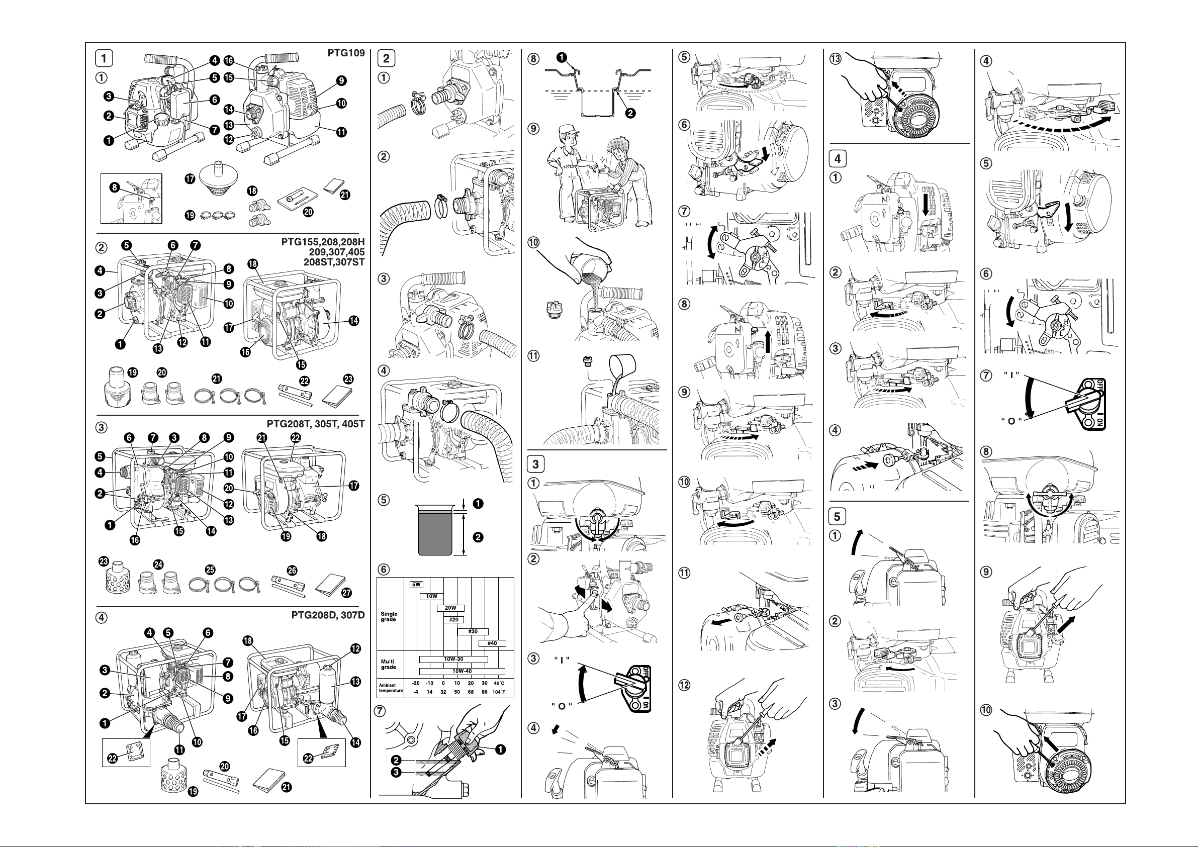
CENTRIFUGAL PUMP (PTG109)
11
(See Fig.
q Tank cap
w Recoil starter
e Starter handle
r Spark plug cap
t Speed control lever
y Air cleaner
u Primer button
4
1
11
-
qq
q)
qq
i Choke lever
o Muffler
!0 Stop Switch
!1 Fuel tank
!2 Plug (drain)
!3 Casing cover
!4 Suction
!5 Delivery
!6 Plug (priming)
!7 Strainer
!8 Hose coupling
!9 Hose band
@0 Tools
@1 Instruction for use
(This publication)
Page 10

CENTRIFUGAL PUMP (PTG155, 208, 208H, 209, 307, 405)
SEMI TRASH PUMP (PTG208ST, 307ST)
11
(See Fig.
1
11
-
ww
w)
ww
NOTE
PTG155 is without frame.
q Plug (drain)
w Suction
e Delivery
r Frame
t Plug (priming)
y Spark plug
u Fuel cock
i Speed control lever
o Choke lever
!0 Muffler
!1 Air cleaner
!2 Drain plug (at two places)
!3 Oil filler (with oil guage)
!4 Casing cover
!5 Stop switch
!6 Recoil starter
TRASH PUMP (PTG208T, 305T, 405T)
11
(See Fig.
q Plug (drain)
w Knob
e Delivery
r Suction
t Frame
y Casing
u Plug (priming)
i Spark plug
o Fuel cock
1
11
-
ee
e)
ee
!0 Speed control lever
(PTG208T,305T)
!1 Chocke lever
!2 Muffler
!3 Air cleaner
!4 Speed control lever (PTG405T)
!5 Oil filler (with oil guage)
!6 casing cover holder
!7 Casing cover
!8 Drain plug (at two places)
!7 Recoil starter handle
!8 Fuel tank
!9 Strainer
@0 Hose coupling
@1 Hose band
@2 Tools
@3 Instruction for use
(This publication)
!9 Recoil Starter
@0 Recoil Starter handle
@1 Stop switch
@2 Fuel tank
@3 Strainer
@4 Hose coupling
@5 Hose band
@6 Tools
@7 Instruction for use
(This publication)
GB
DIAPHRAGM PUMP (PTG208D, 307D)
11
(See Fig.
q Oil filler
(with Oil guage)
w Pump body
e Gear case
r Spark plug
t Fuel cock
y Speed control lever
u Choke lever
1
11
-
rr
r)
rr
i Muffler
o Air cleaner
!0 Drain plug (at two places)
!1 Delivery
!2 Plug (filler)
!3 Suction chamber
!4 Suction
!5 Stop switch
!6 Recoil starter
!7 Recoil starter handle
!8 Fuel tank
!9 Strainer
@0 Tools
@1 Instruction for use
(This publication)
@2 Check valves
5
Page 11

3. PRE-OPERA TION FOR ST ARTING
(See Fig.
22
2
22
)
1. ATTACH THE FLANGE
AND CHECK VALVES
(PTG208D, 307D)
Attach the suction flange, delivery flange and check valves to
the pump when operating the brand new pump for the first time.
CAUTION
Be careful not to overtighten the bolts.
Suction flange tightening torque : 90-120 kg-cm
Delivery flange tightening torque : 90-120 kg-cm
GB
2. CONNECT SUCTION HOSE
22
(See Fig.
(PTG109 only See Fig.
Use a reinforced-wall or wire braided hose to prevent suction
collapse.
Since the pump self-priming time is directly proportional to
hose length, a short hose is recommended.
Always use a strainer with the suction hose. Gravel
or debris sucked into the pump will cause serious
damage to the impeller and the pump casting.
3. CONNECT DELIVERY HOSE
(See Fig.
(PTG109 only See Fig.
When using a fabric hose, always use a hose band to prevent
the hose from disconnecting under high pressure.
4. CHECK ENGINE OIL (Except PTG109)
(See Fig.
Before checking or refilling engine oil, be sure the engine is
located on stable, level surface and stopped.
■
Do not screw the oil gauge into the oil filler neck to check
oil level. If the oil level is low, refill to the upper level with
the following recommended oil.
■
Use 4-stroke automotive detergent oil of API service class
SE or higher grade.
■
Select the viscosity based on the air temperature at the
time of operation as shown in the table. (See Fig.2
Explanation of Fig.
q Oil Gauge
w Upper Level
e Lower Level
2
22
22
2
22
22
2
22
ww
-
w)
ww
CAUTION
rr
-
r)
rr
uu
u)
-
uu
22
2
-
22
22
qq
2
-
q)
22
qq
ee
22
-
e)
2
ee
22
uu
u
uu
Model Oil capacity
PTG155 0.4L
PTG208/PTG208H
PTG208ST/PTG208T
PTG209
PTG307/PTG307ST
PTG208D/PTG307D
PTG405/PTG305T 0.85L
PTG405T 1.2L
0.6L
5. CHECK FUEL
22
(See Fig.
2
22
-
ii
i)
ii
WARNING
Do not refuel while smoking, near an open flame
or other such potential fire hazards. Otherwise
fire accident may occur.
■
Stop the engine and open the cap.
■
Use unleaded automotive gasoline only.
Fuel Tank Capacity
Refer to “9. SPECIFICA TIONS” Page 12 for fuel tank capacity
■
Close the fuel cock before filling the fuel tank.
■
Do not fill above the top of the fuel filter screen (marked w),
or the fuel may overflow when it heats up later and expands.
■
When filling the fuel tank, always use the fuel filter screen.
■
Wipe off any spilled fuel before starting the engine.
(See Fig.2
For PTG109 (See Fig.
■ If level is low, fill to the shoulder of the fuel filter.
■ Use the mixture fuel prepared by mixing gasoline and
exclusive 2-cycle oil at a ratio of 20 to 25 : 1, or the 2-cycle
fuel now available on the market.
-
o)
22
tt
2
t)
-
22
tt
CAUTION
For break-in of a new engine.
Use mixture fuel of gasoline 15 to 20 : 2-cycle
engine oil 1 during first 20 hours of operation.
6. CHECK PRIMING WATER
!0!0
22
-
(See Fig.
-
y)
It is recommended that the water chamber of pump casing
should be primed with full of water before operating.
2
22
!0)
!0!0
WARNING
Never attempt to operate the pump without priming
water or the pump will overheat. Extended dry
operation will destroy the mechanical seal.
If the unit has been operated dry , stop the engine
immediately and allow the pump to cool before
adding priming water.
6
Page 12

4. OPERATING YOUR PUMP
(See Fig.
33
3
33
)
1. STARTING
(1) Open the fuel cock. (See Fig.3-q)
(2) Turn the STOP SWITCH to the position “
(See Fig.3
■
(PTG109 only)
Push the primer button 5 to 7 times to feed the fuel to
the carburetor. (See Fig.3
(3) Set the speed control lever 1/3 to 1/2 of the way towards
the high speed position. (See Fig.3-r,t,y)
■
(PTG405T only)
Set the speed control lever to “START” position
(See Fig.3
(4) Close the choke lever. (See Fig.3
■
If the engine is cold or the ambient temperature is low,
close the choke lever fully.
■
If the engine is warm or the ambient temperature is high,
open the choke lever half-way, or keep it fully open.
(5) Pull the starter handle slowly until resistance is felt. This
is the “compression” point. Return the handle to its
original position and pull swiftly. Do not pull out the rope
all the way. After starting the engine, allow the starter
handle to return to its original position while still holding
the handle. (See Fig.3
(6) After starting the engine, gradually open choke by turning
the choke lever and finally keep it fully opened. Do not
fully open the choke lever immediately when the engine
is cold or the ambient temperature is low, because the
engine may stop. (See Fig.4
-
e)
-
w)
-
u)
-
!3) (PTG109 only 3-!2)
-q,w,e,
” (ON).
I
-i,o,!0,
r)
!1)
2. RUNNING
(1) After the engine starts, set the speed control lever at the
low speed position (L) and warm it up without load for a
few minutes.
(See Fig.5
(2) Gradually move the speed control lever toward the high
speed position (H) and set it at the required engine speed.
(See Fig.5
■
Whenever high speed operation is not required, slow the
engine down (idle) by moving the speed control lever to
save fuel and extend engine life.
-q,
w)
-e,r,t,
y)
3. STOPPING
(1) Set the speed control lever at the low speed position and
allow the engine to run at low speed for 2 or 3 minutes
before stopping.
(See Fig.5
(2) Turn the STOP SWITCH counterclockwise to the position
“ ◯ ” (OFF). (See Fig.5
■Do not stop the engine suddenly when it is running at
high speed.
(3) Close the fuel cock. (Except PTG109) (See Fig.5
(4) Pull the starter handle slowly and return the handle to its
original position when resistance is felt. This operation is
necessary to prevent outside moist air from intruding
into the combustion chamber. (See Fig.5
-q,
w)
-
u)
-
i)
-
o,!0)
※ STOPPING ENGINE WITH THE FUEL COCK
Close the fuel cock and wait for a while until the engine stops.
Avoid to let the fuel remain in the carburator over long periods,
or the passages of the carburator may become clogged with
impurities, and malfunctions may result.
5. MAINTENANCE
(See Fig.
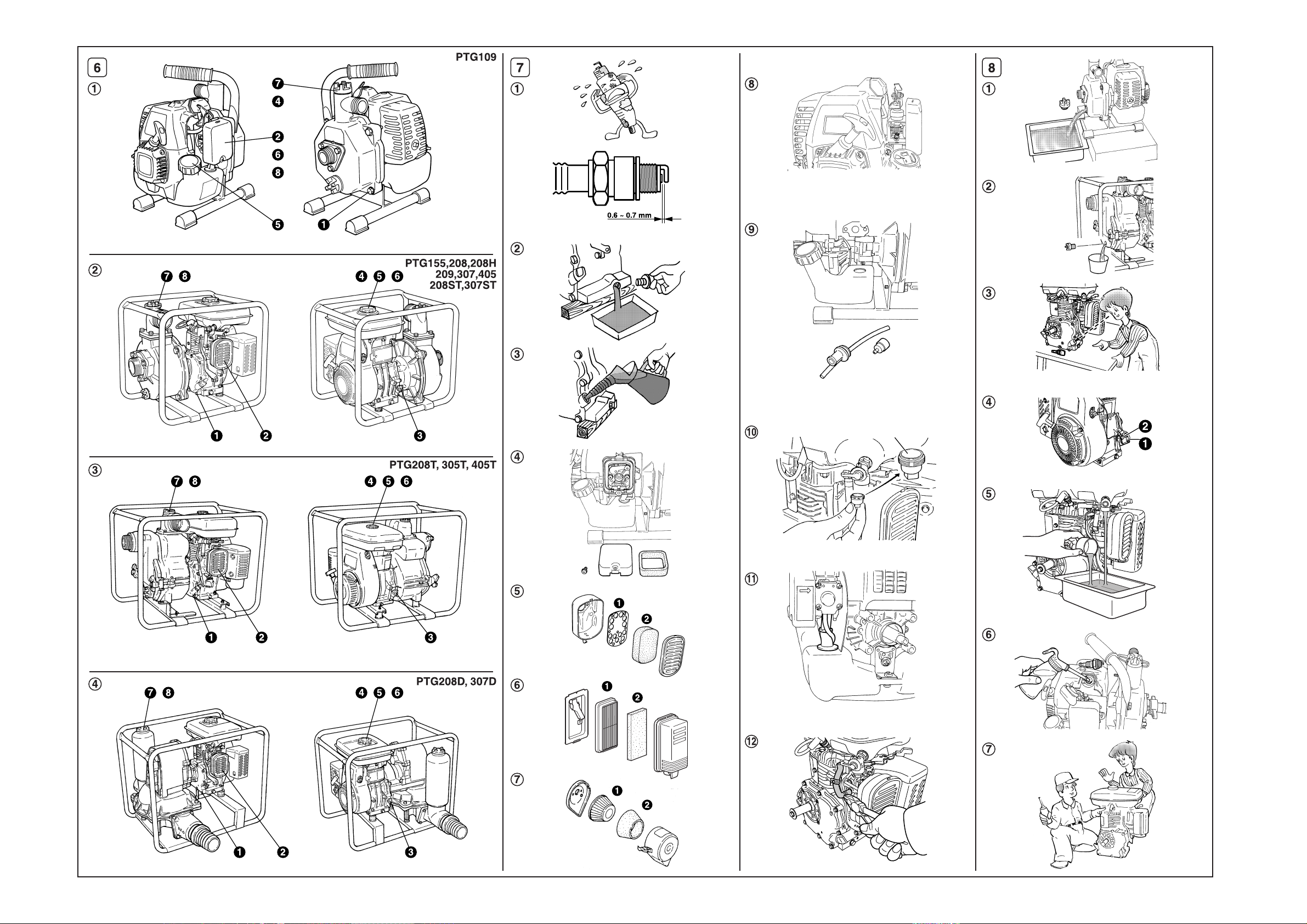
1. DAILY INSPECTION
Before running the engine, check the following service items.
q Loose or broken bolts and nuts
w Clean air cleaner element
e Enough clean engine oil (Except PTG109)
r Leakage of gasoline and engine oil
t Enough gasoline
y Safe surroundings
u Check the priming water
i Excessive vibration, noise
66
6
66
)
GB
7
Page 13

2. PERIODIC INSPECTION
Periodic maintenance is vital to the safe and efficient operation
of your pump.
Check the table below for periodic maintenance intervals. The
below chart is based on the normal pump operation schedule.
(PTG109)
Maintenance items
CLEAN PUMP SET AND CHECK
BOLTS AND NUTS
GB
CLEAN SPARK PLUG
CLEAN AIR CLEANER ●
REMOVE THE PUMP CASING AND
CLEAN
CLEAN FUEL STRAINER
CLEAN AND ADJUST SPARK PLUG
AND ELECTRODES
CLEAN AND ADJUST CARBURETOR
CLEAN FUEL TANK
OVERHAUL ENGINE IF NECESSARY ●
Every
8 hours
(Daily)
● (Daily)
CAUTION
Replace rubber pipes for fuel passage every two
years. If fuel leakage is found, replace the pipe
immediately.
Every
50 hours
(Weekly)
●
Every
200 hours
(Monthly)
●
●
●
Every
500
hours
●
●
Every
1000
hours
(PTG155, 208, 209, 307, 405, 208H, 208ST, 307ST, 208T, 305T, 405T, 208D, 307D)
Maintenance items
CLEAN PUMP SET AND CHECK
BOLTS AND NUTS
CHECK AND REFILL ENGINE OIL
CHANGE ENGINE OIL
CLEAN SPARK PLUG
CLEAN AIR CLEANER
LUBRICATE THE PUMP-ROD
BEARING(PTG208D307D only)
REMOVE THE PUMP CASING AND
CLEAN (Except PTG208D, 307D)
CLEAN FUEL STRAINER ●
CLEAN AND ADJUST SPARK
PLUG AND ELECTRODES
CHECK AND ADJUST VALVE
CLEARANCE
RMOVE CARBON FROM
CYLINDER HEAD
CLEAN AND ADJUST CARBURETOR
CHECK AND REFILL GEAR BOX
GREASE (PTG208D,307D only)
CHECK SUCTION AND DELIVERY
CHECK VALVES
(PTG208D,307D only)
OVERHAUL ENGINE IF NECESSARY ●
Every
8 hours
(Daily)
● (Daily)
(Refill daily up to upper level.)
●
(Intial 20
hours)
Every
50 hours
(Weekly)
●
●
●
●
Every
200 hours
(Monthly)
●
●
Every
300
hours
●
Every
500
hours
●
●
●
●
Every
1000
hours
8
Page 14

3. INSPECTING THE SPARK PLUG
qq
77
-
(See Fig.
(1) Clean off carbon deposits on the spark plug electrode
using a plug cleaner or wire brush.
(2) Check electrode gap. The gap should be 0.6 mm to 0.7
mm (0.02 inch.
by carefully bending the side electrode.
Recommended Spark Plug
Model Spark Plug
PTG109 NGK-BM7A or BMR7A (CHAMPION-C6)
PTG155 NGK-BM4A or BMR4A (CHAMPION-CJ14)
PTG208/PTG209
PTG307
PTG208H
PTG208ST/PTG307ST
PTG208T
PTG208D/PTG307D
PTG405/PTG305T NGK-BP6HS or BPR6HS (CHAMPION-L87C or RL87C)
PTG405T NGK-BP4HS or BPR4HS (CHAMPION-L95YC or RL95YC)
4.
ENGINE OIL CHANGE (See Fig.
q)
7
qq
77
-
0.03 inch.). Adjust the gap, if necessary,
NGK-B6HS or BR6HS (CHAMPION-L86C or RL86C)
77
ww
7
-
w,
77
ww
ee
e)
ee
(Except PTG109)
Initial oil change : After 20 hours of operation
Thereafter : Every 50 hours of operation
(1) When changing oil, stop the engine and loosen the drain
plug. Drain the used oil while the engine is warm. Warm
oil drains quickly and completely.
CAUTION
Make sure the fuel cap is tightly secured to avoid
spillage.
■When changing oil, stop the engine and loosen the
drain plug.
■ Tighten the drain plug before refilling.
■ Refer to the recommended oil table on page 6.
■ Always use the proper grade and clean oil. If the
engine oil is contaminated, there is not enough or
it is of poor quality, engine life will be shortened.
5. CLEANING FUEL STRAINER
oo
!0!0
77
-
o,
(See Fig.
7
77
oo
!0)
!0!0
WARNING Flame Prohibited
6. CLEANING AIR CLEANER
WARNING Flame Prohibited
A dirty air cleaner element will cause starting difficulty, power
loss, engine malfunctions, and shorten engine life extremely.
Always keep the air cleaner element clean.
rr
77
(PTG109) (See Fig.
■
Remove the element and wash it in kerosene or diesel
fuel. Then saturate it in a mixture of 3 parts kerosene or
diesel fuel and 1 part engine oil. Squeeze the element to
remove the mixture and install it in the air cleaner.
(PTG155, 208, 209, 307, 405, 208H, 208ST, 307ST, 208T, 305T,
405T, 208D, 307D)
(1) Urethane Foam Element Type
(See Fig.7
■
Remove the element and wash it in kerosene or diesel
fuel. Then saturate it in a mixture of 3 parts kerosene or
diesel fuel and 1 part engine oil. Squeeze the element to
remove the mixture and install it in the air cleaner.
(2) Urethane Foam Dual Element Type
(See Fig.7
■
Urethane Foam cleaning (See Fig.7-y,u-w)
Wash and clean the urethane foam with detergent. After
cleaning, dry it. Clean the urethane foam element every
50 hours.
■
Second element (See Fig.7-y,u-q)
Clean by tapping gently to remove dirt and blow off dust.
Or wash the element with water, and dry it. Never use
oil. Clean the paper element every 50 hours of operation,
and replace element set every 200 hours.
Clean and replace air cleaner elements more often when
operating in dusty environments.
7
77
-
t)
-
y,u)
r)
-
rr
7. ADJUSTING CARBURETOR (PTG109)
ii
77
-
(See Fig.
Adjusting idling rpm.
When adjust screw is turned right, engine rpm increases, and
when it is turned left, rpm decreases. (Refer to illustration.)
Normal idling rpm 3100± 100rpm
7
77
i)
ii
GB
(PTG109)
(1) Loosen the banjo bolt from the carburetor and remove
the strainer (plastic mesh).
(2) Clean the strainer with kerosene and reassemble it.
(PTG155, 208, 209, 307, 405, 208H, 208ST, 307ST, 208T, 305T,
405T, 208D, 307D)
(1) Inspect fuel strainer for water and dirt.
(2) To remove water and dirt, close the fuel cock and remove
the strainer cup.
(3) After removing dirt and water, wash the strainer cup with
gasoline. Reinstall securely to prevent leakage.
NOTE
The carburetor greatly affects the performance of the
engine.
Since it has been adjusted carefully at our factory
before shipment, avoid adjusting unless absolutely
necessary. If adjustments are needed, contact your
nearest dealer.
9
Page 15

8. FUEL HOSE REPLACEMENT
!1!1
!2!2
77
-
!1,
(See Fig.
7
77
!1!1
!2)
!2!2
WARNING
Take extreme caution when replacing fuel hose ;
gasoline is extremely flammable.
Replace the fuel hose every 2 years. If fuel leaks from fuel
hose, replace the fuel hose immediately.
9. CHECKING BOLTS, NUTS AND SCREWS
■ Retighten loose bolts and nuts.
GB
■ Check for fuel and oil leaks.
■ Replace damaged parts with new ones.
yy
uu
88
-
y,
4. ENGINE OIL (See Fig.
■
Change the engine oil with fresh oil.
■
Remove the spark plug, pour about 5 cc of engine oil
into the cylinder, slowly pull the starter handle of the recoil
starter 2 or 3 times, and reinstall the spark plug.
8
88
yy
u)
uu
5. CLEAN AND STORE
■
Slowly pull the recoil starter handle until resistance is felt
and leave it in that position.
■
Clean the pump thoroughly with an oiled cloth, put the
cover on, and store the pump indoors in a well ventilated,
low humidity area.
10. CLEANING PUMP INSIDE
■ Turn the knob counterclockwise and open the casing
cover holder.
■Pull the casing toward you, and then remove the casing
and the inner casing.
■ Clean the inside of pump casing and casing cover with
clean water.
6. PREP ARATIONS FOR STORAGE
1. WATER (Except PTG208D,307D)
88
qq
(See Fig.
Drain all water from the drain plug.
When retightening drain plug, be sure to clean
the drain plug and the thread of casing. Otherwise,
the thread may be damaged.
2. DISCONNECT THE DELIVERY HOSE
(PTG208D, 307D)
Tilt the pump and drain all water from delivery hole. Severe
damage to pump may result if water freezes in the pumping
chamber.
8
88
-
q,
qq
ww
w)
ww
CAUTION
7. OIL SENSOR INSTRUCTIONS
(Except PTG109)
1. FUNCTION OF OIL SENSOR
The engine will stop automatically when the oil level falls
below the safety limit. The engine cannot be started unless
the level is raised above the prescribed limit.
(See Fig.8
2. RESTARTING
(1) Fill the crankcase with oil up to the proper level.
(2) As for restarting and operating the engine, refer to
■ Check the wire connector from the engine. It must be
■ Do not remove the oil sensor from the engine for
■ When selecting the engine oil, refer to page 6 for the
-
e)
section “4. OPERATING YOUR PUMP” on page 7.
connected securely to the wire from oil sensor.
(See Fig.8
checking oil level and refilling. (See Fig.8
recommended oil.
-r-
w Fix the earth wire.)
(OPTIONAL)
-r-
q)
3. DISCHARGE FUEL
88
(See Fig.
8
88
-
tt
t)
tt
WARNING Flame Prohibited
If you do not use the engine more than 1 month, discharge
fuel to prevent gum in the fuel system and carburetor parts.
■
Remove the strainer cup, place the strainer over a
container and open the strainer cock to discharge fuel
from the fuel tank.
■
Remove the drain screw of the carburetor float chamber
and discharge fuel.
10
Page 16

8. EASY TROUBLESHOOTING
1. PUMP DOES NOT RUN .
■ Engine dose not start.
(See 8.-6 “6. WHEN ENGINE DOES NOT START
■ Sticking of impeller (Except PTG208D, 307D)
(Disassemble and clean.)
■ Solid object preventing pump-rod from completing
stroke. (PTG208D, 307D only)
(Disassemble and clean.)
2. PUMPING VOLUME IS SMALL.
■ Sucking air at suction side.
(Check piping at suction side.)
■ Drop off engine output
(Consult your nearest dealer.)
■ Breakage of mechanical seal.
(Except PTG208D, 307D)
(Consult your nearest dealer.)
■ Debris keeping check valve open.
(PTG208D, 307D only)
(Disassemble and clean.)
■ High suction lift (Lower.)
■ Suction hose is too long or thin.
(Use a thick hose in minimum length.)
■ Leak of water from water passage.
(Stop leaking.)
■ Clogging of foreign substance in impeller.
(Except PTG208D, 307D)
(Disassemble and clean.)
■ Breakage of rubber diaphragm. (Consult your nearest
dealer) (PTG208D, 307D only)
■ Wear of impeller. (Except PTG208D, 307D)
■ Looseness of suction chamber. (Retighten) (PTG208D,
307D only)
■ Strainer is clogged. (Clean.)
■ Engine speed is too low.
(Consult your nearest dealer.)
3. PUMP DOES NOT SELFPRIME.
■ Suction of air at suction side.
(Except PTG208D, 307D)
(Check piping at suction side.)
■ Insufficient priming water inside pump casing
(Except PTG208D, 307D)
(Prime fully.)
■ Imperfect tightening of drain plug.
(Except PTG208D, 307D)
(Tighten the plugs completely.)
■ Engine speed is too low.
(Except PTG208D, 307D)
(Consult your nearest dealer.)
■ Sucking air from mechanical seal.
(Except PTG208D, 307D)
(Consult your nearest dealer.)
4. DELIVERY HOSE DOES
NOT STAY ON COUPLING.
”)
■ Hose may be kinked or discharge end may be blocked
or clogged.
(PTG208D, 307D only)
(Straighten or clean.)
5. PUMP SUDDENLY STOPS.
■ Solid object preventing pump-rod from completing stroke.
(PTG208D, 307D only)
(Disassemble and clean.)
6. WHEN ENGINE DOES NOT START :
GB
Perform the following checks before you take the pump to
your Robin dealer. If you still have trouble after completing
the checks, take the pump to your nearest Robin dealer.
WARNING
Before testing, carefully wipe off spilled fuel.
Put the plug as far away from the spark plug hole
as possible.
Ground the side of the electrode to any engine
ground.
(1) Is there a strong spark across the electrode ?
■ Remove the spark plug and connect it to the plug cap.
Pull the starter handle while grounding spark plug against
engine body.
■Try with a new spark plug if the spark is weak or there is
no spark.
■ The ignition system is faulty if there is no spark with a
new spark plug.
(2) Is there enough compression?
■ Pull the starter handle slowly and check if resistance is
felt.
■If little force is required to pull the starter handle, check if
the spark plug is tightened firmly.
■If the spark plug is loose, tighten it.
(3) Is the spark plug wet with fuel?
■ Is the fuel cock opened? (Except PTG109)
■ Choke (close choke lever) and pull the starter handle five
or six times. Remove the plug and check if its electrode is
wet. If the electrode is wet, fuel is well supplied to your
engine.
■ When the electrode is dry, check where the fuel stops.
(Check the fuel intake of the carburetor and fuel strainer
intake.)
■ In case the engine does not start with well supplied fuel,
try using fresh fuel.
11
Page 17

9. SPECIFICATIONS
Model
Type
Suction×Delivery Diameters
Total Head
Maximum Delivery Volume
PUMPENGINE
Suction Head
Axle Seal Material(Mechanical Seal)
Model
Type
Lubricant
Oil Capacity
Fuel
Fuel Tank Capacity
GB
Spark Plug
Starting System
Dimensions (L×W×H)
Net Weight
Standard Accessories
Model PTG208ST PTG307ST PTG208T
Type
Suction×Delivery Diameters
Total Head
Maximum Delivery Volume
PUMPENGINE
Suction Head
Axle Seal Material(Mechanical Seal)
Model
Type
Lubricant
Oil Capacity
Fuel
Fuel Tank Capacity
Spark Plug
Starting System
Dimensions (L×W×H)
Net Weight
Standard Accessories
PTG109 PTG155 PTG208
25.4×25.4mm(1×1in.)
35m 23m
120 /min
8.5m
EC025GR
Robin Air-cooled, 2-stroke, Gasoline engine
Mixture fuel
(Automobile gasoline : Engine oil=25:1 )
0.6L 1.5L
NGK-BM7A or BMR7A
(CHAMPION-CJ6)
275×212×298mm 382×285×357mm
5.1kg
38.1×38.1mm(1.5×1.5in.)
320 /min
EY08D EY15-3D
Automotive detergent oil (API/SE or higher grade, SAE/10W-30 etc.)
0.4L
NGK-BM4A or BMR4A
(CHAMPION-CJ14)
9.8kg
Engine tool kit (1 set), Strainer (1 pc.), Hose coupling (2 pcs.), Hose band (3 pcs.)
Self-priming, Centrifugal pump
50.8×50.8mm(2×2in.)
32m
520 /min
Ceramic-carbon
Robin Air-cooled, 4-stroke, Gasoline engine
NGK-B6HS or BR6HS (CHAMPION-L86C or RL86C)
Recoil starter
470×354×419mm
23.5kg
PTG209 PTG307 PTG405
26m
600 /min
8m
0.6L
Automobile gasoline
2.8L
475×344×414mm
22.5kg
76.2×76.2mm(3×3in.) 101.6×101.6mm(4×4in.)
32m
1000 /min
EY20-3D
527×378×422mm
26.4kg
PTG305T PTG405T PTG208H
Self-priming, Centrifugal pump
50.8×50.8mm(2×2in.) 76.2×76.2mm(3×3in.) 50.8×50.8mm(2×2in.)
700 /min
EY15-3D
2.5L 3.8L 5.5L 6.0L 3.8L
462×356×397mm 527×368×417mm
24kg
23m
1000 /min
EY20-3D EY28D
Automotive detergent oil (API/SE or higher grade, SAE/10W-30 etc.)
0.6L
NGK-B6HS or BR6HS (CHAMPION-L86C or RL86C)
28kg
Engine tool kit (1 set), Strainer (1 pc.), Hose coupling (2 pcs.), Hose band (3 pcs.)
27m
750 /min
Robin Air-cooled, 4-stroke, Gasoline engine
600×398×448mm
34.8kg
Self-priming, Trash pump
76.2×76.2mm(3×3in.) 101.6×101.6mm(4×4in.) 50.8×50.8mm(2×2in.)
1300 /min
8m
Silicon-carbide
Automobile gasoline
NGK-BP6HS or BPR6HS
(CHAMPION-L87YC or RL87YC)
Recoil starter
690×485×600mm
28m
0.85L 1.2L
45kg
23m
2000 /min
EY40D EY20-3D
NGK-BP4HS or BPR4HS
(CHAMPION-L95YC or RL95YC)
730×485×600mm
71.4kg
28m
1800 /min
EY28D
0.85L
5.5L3.8L
NGK-BP6HS or BPR6HS
(CHAMPION-L87YC or RL87YC)
618×485×570mm
44.1kg
Self-priming, Centrifugal pump
50m
400 /min
0.6L
NGK-B6HS or BR6HS
(CHAMPION-L86C or RL86C)
527×378×422mm
26.5kg
Model PTG208D PTG307D
Type
Suction×Delivery Diameters
Total Head
PUMPENGINE
Maximum Delivery Volume
Suction Head
Model
Type
Lubricant
Oil Capacity
Fuel
Fuel Tank Capacity
Spark Plug
Starting System
Dimensions (L×W×H)
Net Weight
Standard Accessories
50.8×50.8mm(2×2in.)
125 /min
EY15-3D
Automotive detergent oil (API/SE or higher grade, SAE/10W-30 etc.)
614×370×510mm
37.4kg
Self-priming, Diaphragm pump
15m
7.6m
Robin Air-cooled, 4-stroke, Gasoline engine
0.6L
Automobile gasoline
2.8L 3.8L
NGK-B6HS or BR6HS (CHAMPION-L86C or RL86C)
Recoil starter
Engine tool kit (1 set), Strainer (1 pc.)
12
76.2×76.2mm(3×3in.)
250 /min
EY20-3D
660×420×540mm
44.8kg
 Loading...