

Page 1

RCBERTSHAW DELUXE PROGRAMMABLE THERMOSTATS
MEET CA TITLE 24 REQUIREMENTS
Robertshaw warrants to the original purchaser that this product
and its component parts will be free from defects in workmanship
and materials for a period of two years from the date of purchase.
Your dealer will provide free replacement of the product upon
proof of purchase.
This warranty does not apply in the event of misuse, abuse or as
a result of unauthorized alterations or repairs. Robertshaw will
not be liable for any consequential damages including, without
limitation, damages resulting from defects, loss of use or misuse.
NORTH AMERICA
ROBERTSHAW CONTROLS COMPANY
l
UNI-LINE NORTH AMERICA l P.O. BOX 2000 l CORONA, CA
PRINTED IN CANADA 1
996
Robertshaw
Company
97255 ALTO1
l-898
TABLE OF CONTENTS
INTRODUCTION
...........................................................................................................
4
STANDARD FEATURES
............................................................................................
4-6
THERMOSTAT LOCATION
............................................................................................
7
REMOVING THE THERMOSTAT FROM THE SUBBASE
..............................................
8
DESCRIPTION OF THE DIPSWITCH FUNCTIONS
.................................................
9-11
COVER LOCK
.............................................................................................................
12
REPLACING THE THERMOSTAT ON THE SUBBASE
................................................
12
WIRING DIAGRAMS
..............................................................................................
13-24
PROGRAMMING 7 DAY MODELS
.........................................................................
26-29
PLANNING YOUR SCHEDULE
.................................................................................
25
THE CURRENT
.......................................................................
26
SETTING YOUR PROGRAM TEMPERATURES
......................................................
SETTING YOUR PROGRAM TIMES
.........................................................................
27
TEMPERATURE OVERRIDE
....................................................................................
28
CHANGING FAHRENHEIT (“F) TO CELSIUS
....................................................
29
CHANGING 12 HOUR TIME TO 24 HOUR TIME
......................................................
29
Installation
Programming Instructions
for
Deluxe Programmable Thermostats
POWER FAILURES
.................................................................................................
OUTDOOR TEMPERATURE INDICATOR (OPTIONAL)
............................................
29
PROGRAMMING
DAY MODELS
.....................................................................
TYPICAL RESIDENTIAL SCHEDULE
.......................................................................
30
PLANNING YOUR SCHEDULE
.................................................................................
31
SETTING THE CURRENT DAY/TIME
......................................................................
SETTING THE WEEKDAY PROGRAM TIMES AND HEATING TEMPERATURES
32-33
SETTING THE WEEKDAY AND WEEKEND COOLING TEMPERATURES
..........
33-34
REVIEWING SCHEDULED TIMES AND TEMPERATURES
........................................
35
CHANGING SCHEDULED TIMES AND
...........................................
35
SPECIFICATIONS
..................................................................................................
36-37
IMPORTANT INSTALLER’S NOTE
........................................................................
IMPORTANT: Read this manual thoroughly to understand all
I----
the features of your deluxe programmable thermostat.
Page 2
INTRODUCTION
The Deluxe Programmable Thermostat represents the most advanced solid-state, microcomputer temperature control on the market today. The thermostat incorporates state-of-the-art
technology packaged in an extremely low profile designer series case. Ultra-Touch controls are
combined with a easy-to-read, full function liquid crystal display to provide the ultimate in “user
friendly” operation of your heating and air conditioning equipment.
STANDARD FEATURES
No batteries required
always remembers scheduled events and temperatures
100% Solid State circuitry
Computerized heat anticipation and cooling droop
Built-in short cycle protection during normal operation
Tamper proof electronic keyboard lockout
Auto or Manual fan operation
Auto or Manual Heat/Cool changeover*
Constant Hold feature allows continuous override
Temporary temperature override
Selectable 12 or
24
hour clock display
Selectable Fahrenheit or Celsius temperature display
Lockable Access Cover
Full Function Liquid Crystal Display (LCD)
l
No Auto changeover on
or 230
4
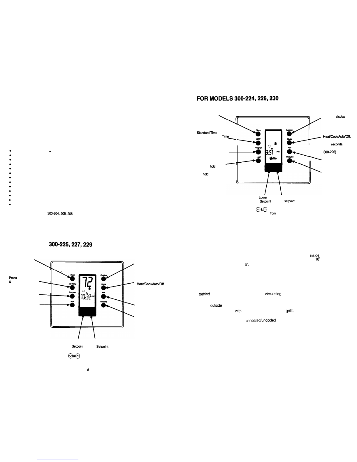
FOR MODELS
Press to set the
real time Day,
Hour and Minute
to set the Heating
Cooling setpoints
Press to set program
days and times
Press to hold the current
setting. The program will
hold indefinitely or until
RESUME is pressed
Press to display the
outdoor temperature
(Optional)
Press to select
The word is displayed
for 5 seconds.
(Emergency heat for
300227)
Select for continuous
Fan or Auto Fan
Press to exit the
hold
or override program,
or when programming
is complete
Press to set the
real time Day,
Press to
the
Hour and Minute
outdoor temperature
(Optional)
Press to change from
to
Press to select
Daylight Savings
12
The word is displayed
Press to set program
for 5
temperatures and
(Emergency Heat for
start times
Select for continuous
Fan or Auto Fan
Press to
the current
setting. The program
Press to exit the hold
will
indefinitely or
until RESUME is
or override program,
or when programming
pressed
is complete
To
To Raise
the
the
Press
at the same time to change
the temperature
Celsius to Fahrenheit
5
THERMOSTAT LOCATION
To
ensure proper operation, the thermostat should be mounted on an
wall in a frequently
occupied area of the building.
In addition, its position must be at least
(46
cm) from any
outside
wall, and approximately
(1.5 m) above the floor in a location with freely circulating air
Of
an average temperature.
Be sure to avoid the following locations:
l
doors or in corners where freely
air
IS
unavailable
l
where direct sunlight or radiant heat from appliances might affect control operation
l
on an
wall
l
adjacent to, or in line
conditioned air discharge
stairwells or outside doors
l
where its operation may be affected by steam or water pipes or warm air stacks in an
adjacent partition, or by an
area behind the thermostat
l
where its operation will be affected
by the supply air of an adjacent unit
l
near sources of electrical Interference such as arcing relay contact
To Lower To Raise
the
the
Press
at the same time to change
the temperature from Celsius to Fahrenheit
Page 3
REMOVING THETHERMOSTAT FROM THE SUBBASE
DESCRIPTION OF THE DIPSWITCH FUNCTIONS
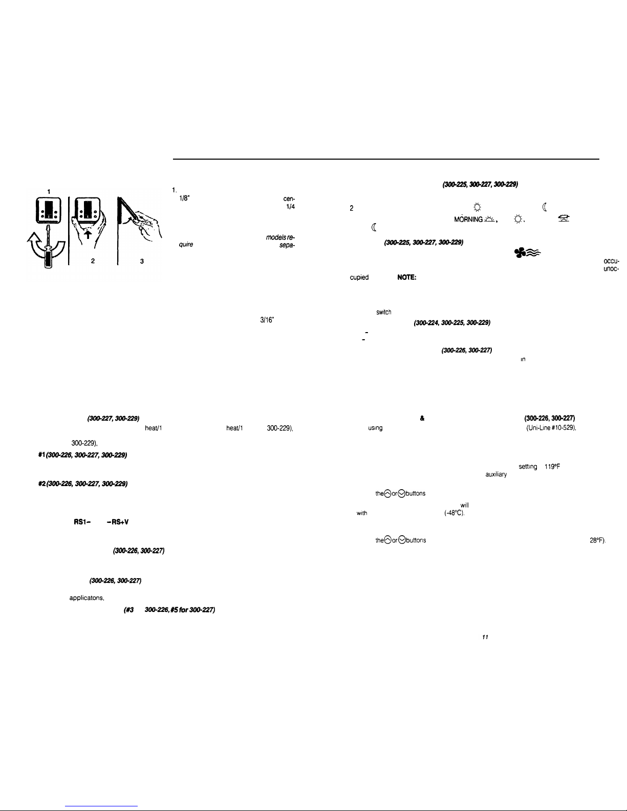
Insert a flat blade screwdriver, or a coin,
2 Events or 4 Events Per Day
the case from the bottom two corners and
separate from the subbase as shown in
the diagram at the left. Some
more force than others when
rating due to the number of terminals used.
2. Swing the thermostat out from the bottom.
3. Lift the thermostat up and off the subbase.
into the slot located in the bottom
ter of the thermostat case and
twist
turn. When you feel or hear a “click”, grasp
4 EVENTS will allow you to
program
DAY EVENING
and
NIGHT
settings.
Smart
Fan (3MM26,3l%?27,3lW?29)
When the Smart Fan switch is in the on position and the Fan
has been energized (during
the occupied program), the thermostat will keep the fan running continuously during the
pied programs and automatically cycle the fan with a call for heating or cooling during the
program.
The unoccupied program is the night program.
Your thermostat can be set to either 2 events or 4 events per day.
EVENTS will allow you to program a DAY
setting and a NIGHT
setting.
4. Place the rectangle opening in the subbase over the equipment control wires protruding from
the wall and, using the subbase as a template, mark the location of the two mounting holes
(exact vertical mounting is necessary only for appearance).
5. Use the supplied anchors and screws for mounting on drywall or plaster: drill two
(5mm)
diameter holes at the marked locations; use a hammer to tap the nylon anchors in flush to the
wall surface and fasten subbase using the supplied screws. (Do not overtighten!)
6. Connect the wires from your system to the thermostat terminals as shown in the wiring diagrams.
Carefully dress the wires so that any excess is pushed back into the wall cavity or junction box,
Ensure that the wires are flush to the plastic subbase. The access hole should be sealed or
stuffed to prevent drafts from the wall affecting the thermostat.
a
Single or Multistage
For equipment with single compressor (2
cool for 300-227 or 1
cool for
switch to “single stage”.
For equipment with two compressors (3 heaV2 cool for 330-227 or
2 heaV2 cool for
switch to “multistage”.
LED #l (300226,306-227,3W&?9)
Switch “on” will energize the LED light pipe at the top of thermostats plus the filter indicator on the
display. This would indicate filter needs changing.
LED
Switch “on” will energize the LED light pipe at the top of thermostats plus the wrench indicator on
the display. This would indicate service is required.
FEATURES
Remote Sensor RS2
The thermostat is designed to accept the Remote Sensor (10528) which will allow you to locate
your thermostat in area away from view.
LED Auxiliary Heat Indicator
Your thermostat is equipped with a LED that indicates when the system has engaged auxiliary
heat mode. It is the center (RED) LED.
Add-On Heat Pumps
Your thermostat is equipped to enhance the performance of an “Add-On” heat pump. The thermostat, in most
will perform the function of a fossil fuel kit.
To select “Add-On”, place switch
for
to the “ON” position. The
thermostat will turn off the compressor with a call for “AUX” heat, When the switch is set to normal,
the thermostat allows the compressor and the “AUX” heat to be on simultaneously.
10
2
Minute or 4 Minute Minimum On Times
Keypad Lock
Place the
in the “Locked” position to lockout all buttons except the Outdoor Temperature button.
Plenum Fan Switch
OFF
Fan comes on immediately with heat (used on electric heat).
ON
The fan is controlled by the system (used on gas/oil heat).
Standard/Add-on Heat Pump
For most heat pump applications, this switch should be left
the “Standard” position. This will
allow the compressor and the auxiliary heat to be on simultaneously. For add-on heat pumps, or
heat pumps that require fossil fuel kits, move this switch to the “Add-on” position. This will turn off
the compressor with a call for auxiliary heat.
9
Setting the Outdoor Hi
Lo Temperature Balance Points
When
the optional Robertshaw Remote Outdoor Sensor
#lo-529) you can select
the outdoor balance points to lock-out the auxiliary heat and/or the compressor of the heat pump.
To set the balance points:
1. Press and hold the OUTDOOR button, then press the MODE button. “HibP” will appear in the
display meaning HI balance point, along with the factory
of
(48°C). Any outside
temperature above the “HibP” will lock out the
heat. any temperature below the “HibP”
will allow the auxiliary heat to run when called for by the thermostat.
2. Press
to set the “HibP” temperature. (A typical setting may be 52°F).
3. Press the OUTDOOR button. “LobP”
appear in the display meaning Lo balance point, along
the factory setting of -54°F
Any outside temperature below the “LobP” will lock out
the compressor, any temperature above the “LobP” will allow the compressor to run when
called for by the thermostat.
4. Press
to set the “LobP” temperature. (A typical setting may be
5. Press the RESUME button
Page 4

WIRING DIAGRAM
You may also lock the cover down to prevent unauthorized access to the thermostat by adding the
clear plastic lock (included in the installation bag). To install, remove the thermostat from the
subbase and place the clear plastic lock in the subbase as shown below. Replace the thermostat
and close the cover. The cover is now locked. To open, simply use a screwdriver to push the lock
back, allowing the cover to open. To remove the lock, open the cover, remove the thermostat from
the subbase, then remove the lock.
REPLACING THE THERMOSTAT ON THE SUBBASE
1. Position the thermostat on the hinged tabs located at the top of the subbase.
2. Gently swing the thermostat down and press on the bottom center edge until it snaps in place.
12
OUTPUT
TERMINAL FUNCTIONS
r
OFF ON
4
min. (on/off)
2
min. (on/off)
Unlocked
Locked
Electric
Gas
RH
. . . . . . . . . . . . .
24VAC
supply
from
heating
W
. . . . . . . . . . . . . . .
Energizes
the
heating
equipment
with a call for heating
RC
. . . . . . . . . . . . .
24VAC
supply
from
cooling
Y
. . . . . . . . . . . . . . . .
Energizes
the
cooling equipment
with a call for cooling
G
. . . . . . . . . . . . . . .
Fan
is
energized
with
a call
for
Heating
or Cooling or selected by pressing the
Fan button Heating mode.
. . . . . . . . . . .
Use to
connect Outdoor
Temperature Sensor and/or
Indoor Remote Sensor Options.
Refer to the instructions included
with the sensors.
Equipment load resistors(proivided) may be required
on the W, Y and G switching circuits if the equipment
loads do not draw
amps.
Connect load resistors at the equipment.
‘See important installer’s note on page 38 and 39.
Line
W
Voltage
G
300-224
13
WIRING DIAGRAM
Note 1:
If jumper removed, a
separate transformer must be used to
power the loads.
Note
2: This thermostat may be used
with 24 Volt DC. The negative side of
the DC supply must be wired to the
24V (C) terminal.
Note 1
G
24V
Note 2
24 VAC
Transformer
74
15
Page 5

OUTPUTTERMINAL FUNCTIONS
wl
G
. . . . . . . . . . . . .
Energizes on a call for first stage heat
. . . . . . . . . . . . . .
Energizes with a call for cooling
G
. . . . . . . . . . . . . . .
Fan is energized with a call for heating
or selected by pressing the fan button
. . . . . . . . . . . . . . .
Independent switching voltage’
24V
. . . . . . . . . . . .
24 VAC hot from the equipment
transformer
. . . . . . .
24 VAC common from the equipment
transformer
WIRING DIAGRAM
300-226
RS2
. . . . . . . . . . .
Use to connect outdoor temperature
sensor and/or indoor remote sensor
options. Refer to the instructions
included with the sensors.
OFF ON
4 events
2 events
Smart fan “OFF
“ON”
4 min. (on/off)
2 min. (on/off)
Unlocked
Locked
Electric
Gas
l
Allows for DC operation required on some older
Lennox and
units.
To replace a dual transformer system, connect the
hot lead of the higher rated transformer (Tl) to the
24V terminal. Connect the common to the
Connect the common of the second transformer to
the common lead of the
and tape off or wire nut the
hot lead of T2.
l
Important: Switch
must be left in “OFF” position
16
17
OUTPUT TERMINAL FUNCTIONS
WIRING DIAGRAM
as2
4
24
0
Off ON
. . . . . . . . . . . . .
Auxiliary Heat is energized as second stage
heating or Emergency Heat
. . . . . . . . . . . . . .
Compressor is energized with a call for Heating or
Cooling
G
. . . . . . . . . . . . . . .
Fan is energized with a call for Heating or Cooling
or selected by pressing the Fan button
. . . . . . . . . . . . . . .
Independent Switching Voltage*
24V
24 VAC Hot from the equipment transformer
c)
. . . . . . . . .
24 VAC common from the equipment transformer
LED1. . . . . . . .
Free lights for status or function indication
LED 2
RS2
. . . . . . . . . . .
Use to connect outdoor temperature Sensor
and/or indoor Remote Sensor Options. Refer
to the instructions included with the sensors.
0
. . . . . . . . . . . . . . .
Energizes the reversing continuously
the Cooling
mode.
B
. . . . . . . . . . . . . . .
Energizes the reversing continuously in the Heating
and off modes.
Note
1:
If jumper is removed, the
terminal may be used to accommodate
independent switching circuits,
Note
2: This thermostat may be used
The negative side of the
be wired to the 24V (C)
Note 1:
If jumper
IS
removed, a separate
transformer must be used to power the loads.
Note
2: This thermostat may be used with 24
Volt DC. The negative side of the DC supply
must be wired to the 24V (C) terminal.
r2
G
Line
Voltage
24
VAC
Transformer
separate
used
Page 6

w2
. . . . . .
-........ Energizes auxiliary heat as second stage
emergency heat
. . . . . . . . . . . . . . . . . . . .
Energizes
compressor
no.
2
on a
call for
second stage heating or cooling
. . . . . . . . . . .
Energizes
auxiliary heat as
last stage heating or
first stage emergency heat
. . . . . . . . . . . . . . “.“. Energizes
compressor
no.
1
on a call
for
first stage heating or cooling
. . . . . . .
. . . . . . .
Fan
is energized
with
a call
for heating
or cooling or by pressing the fan button
. . . . . . . . . . . . . . . . . . . .
Independent
switching
voltage’
24V
. . . . . . . . . . . . . . . . .
VAC
hot
from
the
equipment
transformer
. . . . . . . . . . . . . 24 VAC
the equipment transformer
. . . . . .
Free lights for status
LED2
or function indication
RS2
. . . . . . . . . . . . . . . . .
Use
to connect outdoor
temperature sensor
indoor remote sensor options. Refer
RS+V
to the instructrons included with the sensors.
0
. . . . . . . . . . . . . . . . . . . . .
OFF ON
Energues the
reversing continuously
in
theBcooling mode
. . . . . . . . . . . . . . . . . . . . . Energizes the
reversing
continuouslyinthe heating
and
off
4
events
2 events
modes.
Smart fan “OFF
‘ON’
NO
. . . . . . . . . . . . . . . . . . . Relay
coilisde-energized
in
the night
4
min. (on/off)
COM
2 min. (on/off)
event. In all other events, the relay coil is
NC
ener
Unlocked
Locked
l
Allows for D
operation required on some older
Standard
Add-on
Lennox and McQuay units.
Single stage
Multistage
To replace a dual transformer system, connect the hot
LED #l only
LED #l with filter symbol
lead of the
rated transformer (Tl) to the 24V
LED
only
LED
with fault symbol
terminal. Connect the common to the
Connect
the common of the second transformer to the common
lead of the
and tape off or wire nut the hot lead of T2.
20
OUTPUTTERMINAL FUNCTIONS
300-229
wl
OFF ON
4 events
Smart fan “OFF
4 min. (on/off)
Unlocked
Electric
Single stage
LED
only
2 events
“ON”
2 min. (on/off)
Locked
Gas
Multistage
LED #2only
w2
. . . . . . . . . . . . . . . . . . .
auxiliary
heat
as
second
stage
emergency heat
Y2
. . . . . . . . . . . . . . . . . . . .
compressor no. 2 on a call for
second stage heating or cooling
auxiliary heat as last stage
or
first stage emergency heat
. . . . . . . . . . . . . . . . . . . .
compressor no. 1 on a call for
first stage heating or cooling
G
. . . . . . . . . . . . . . . . . . . . . Fan
is
energized
with a
call
for
heating
or cooling or by pressing the fan button
R
. . . . . . . . . . . . . . . . . . . . .
Independent
switching
voltage’
24V
. . . . . . . . . . . . . . . . . .
24
VAC
hot from
the
. . . . . . . . . . . . .
24 VAC common from the equipment transformer
LED1
. . . . . . . . . . . . . . .
Free
status
LED2
or function indication
Use to connect outdoor temperature sensor
and/or
remote sensor
Refer
RS+V
to the
included
the sensors
0
Energizes the reversing continuously
the
mode
B
. . . . . . . . . . . . . . . . . . . . .
Energizes the
reversing continuously
the
heating and
off
modes
NO
. . . . . . . . . . . . . . . . . . .
Relay
IS
de-energized in the night
COM
event In all other events, the relay
NC
energized.
l
Allows for DC operation required on some older
Lennox and McQuay units.
To replace a dual transformer system, connect the hot
_
LED
with filter symbol
lead of the higher rated transformer
to the
terminal. Connect the common to the
Connect
LED
with fault symbol
the common of the second transformer to the common
or wire nut the hot lead of T2.
WIRING DIAGRAM
Note 1:
If jumper
IS
removed, a separate
transformer must be used to power the loads.
Note
2: This thermostat may be used with 24
Volt DC. The negative side of the DC supply
must be wired to the 24V (C) terminal.
OCC
Common
a-
Transformer
separate
used
21
WIRING DIAGRAM
Transformer
Line
Voltage
Page 7

PLANNING YOUR SCHEDULE
. .
. . 24VAC
supply
cooling
equipment transformer
q
I
Y. . . . . . uI . . . .
Energizes the cooling equipment with a
call for
cooling
Fan is
energized withacall forCooling of
selected by pressing
Fan button
. . . . . . . . .
Use
to connect Outdoor Temperature
Sensor and/or Indoor Remote
Options. Refer to the instructions
included with the sensors.
Equipment load resistors(proivided) may be required
on the Y and G switching circuits if the equipment
loads do not draw
amps per circuit minimum.
OFF ON
Connect load resistors at the equipment.
4 minute. (min. on)
q
2 minute (min. on)
Keypad unlocked
Keypad Locked
24
THE CURRENT
DAY/TIME
Press the CLOCK button.* The display will flash a day of the week.
Press the@
buttons until the current day shows.
Press the CLOCK button again. The display will flash the hour.
(Note the
AM/PM indicator).
Press the@
buttons until the current hour shows.
Press the CLOCK button again. The display will flash the minutes.
Press the@
buttons until the current minutes show.
Press the CLOCK button and the current day and time are now set.
* Note: If a button is not pushed in 15 seconds, the thermostat will automatically return
to normal operation.
With your specific program determined, you are ready to begin programming. You will now
enter the individual program period temperatures
for the heating program.
5
6.
7.
Press the MODE button until
HEAT is displayed.
Press the SET TEMP button.’ The first program period (Morning) will be displayed.
Press the@o@buttons to adjust that program periods desired temperature for heating.
Repeat Steps 2
3 for the Day, Evening and Night program periods. Remember,
your
thermostat was set-up for 2 program periods, you will only have to repeat Steps 2
3 for
the Night program period.
Press the MODE button until COOL is displayed. You will now enter the individual
program period temperatures for the cooling program.
Repeat Steps 2, 3 & 4 for the cooling temperatures.
Press the MODE button until your desired mode of operation appears: HEAT-AUTO-OFF-COOL.
Press the RESUME button to return to normal operation.
l
Note: If a button
IS
not pushed in 15 seconds, the thermostat
automatically return to normal operation. You may
go
back
the
portion
by repeatedly pressing the SET
button
you get back
to
where you left off
26
Your new Robertshaw programmable thermostat has been designed so that you can
either 2 program periods (Day or Night) or 4 program periods (Morning, Day, Evening or Night;
The thermostat comes from the factory set for 4 program periods. To change this setting,
please refer to the “2 Events or 4 Events Per Day” section on page 8.
To help save programming time, we suggest you use the worksheet below to set-up your
specific program.
Note: If you plan to use the Automatic Changeover Mode, you can not set your heating and
cooling temperatures closer than 2 degrees
apart
for the same program period.
Programming Chart
PROGRAM PERIOD
MORNING
DAY
EVENING
NIGHT
HEAT
TEMPERATURES
HEAT:
HEAT
HEAT:
COOL:
COOL.
COOL:
COOL:
(TIME)
(TIME)
(TIME)
(TIME)
Monday
Tuesday
Wednesday
Thursdav
Saturday
I
Sunday
25
SETTING YOUR PROGRAM TIMES
Referring to your Schedule Planner, you will now enter the times for the program periods.
Press the PROGRAM button. The display will flash a day of the week.
2. Press the@
buttons to select the day you wish to program. (We suggest
starting with Monday)
3. Press the PROGRAM button. The display will flash the hour of the first period
(Morning). (Note the AM/PM indicator).
8.
9.
Press
buttons to adjust the desired hour for the first program period.
Press the PROGRAM button again. The display
flash the minutes.
Press
to adjust the desired
for the first period. (Note
the minutes are in Increments of 10).
Repeat Steps 3-6 for the Day, Evening and Night periods. Remember, if your
thermostat was set-up for 2 program periods, you will only have to repeat Steps
3-6 for the Night period.
After entering the Night period, press the PROGRAM button. “COPY” will be
displayed. The COPY function will allow program times to be copied to sequential
days.
If you do not
to copy the program times to another day (or block of
days), proceed to Step 11
Press
buttons to select the next individual day, or block of days, to
copy the program times to.
the PROGRAM button to copy the program times to the selected days of the week.
1
Steps l-10 for any remaining unprogrammed days of the week.
finished, you can verify that all program periods are programmed correctly
by repeated pressing the PROGRAM button. When “COPY” appears, press the
PROGRAM button to skip to the next day.
l
Note: If a button is not pushed in 15 seconds, the thermostat will automatically return to normal operation. You
may easily go back into the programming portion simply by repeatedly pressing the PROGRAM button
you
get back to where you left off.
37
Page 8

TEMPERATURE OVERRIDE
Temporary Override (3 hours)
You
may temporarily change the temperature setting at any time without
affecting the program.
l
Press
buttons. The current event temperature and mode of
operation will be displayed. Press the@o@buttons again to temporarily
adjust the temperature. This temperature will be maintained for three hours.
To cancel, simply press the RESUME button.
Temporary Override w/keyboard
(1 hour)
You
may temporarily change the temperature setting at any time without
affecting the program, even though the keypad is locked out.
l
Press
buttons. The display will show the temperature for the first
event. Press
buttons again to temporarily adjust the temperature
degrees. This temperature will be maintained for one hour.
Continuous Override (Hold)
You
may also maintain a constant temperature setting at any time without affecting the program.
1. Press and release the
button until the desired mode is displayed
(Heat
Auto
Off
Cool)
2. Press and release the HOLD button. “Hold” will be displayed.
3. Press
buttons to adjust the temperature.
This temperature will be maintained
indefinitely. To cancel, simply press the RESUME button.
Note: If the AUTO mode is used, press the MODE button, then press
buttons to
select a heating setpoint. Press the MODE button, and then press
buttons to
select a cooling setpoint.
28
TYPICAL RESIDENTIAL SCHEDULE (3000224,300-226,300-230)
PLANNING YOUR SCHEDULE
Settings
AM/PM
HEAT
68
6:00 AM
8:00 AM
COOL 72
DAY
HEAT
64
9.00 AM
AM
COOL 85
HEAT
68
EVENING
330PM
COOL 72
NIGHT
HEAT
62
10.30 PM
COOL
78
The first
to do before programming your thermostat
IS
to determine your
own personal
comfort
levels for each day as to temperature and time. Shown above is a
schedule.
On the weekdays, after the temperature has been lowered all night, it would be typical to have
the thermostat begin to warm the house at 6:00 AM, if you get up at 700 AM. At 9:00 AM, after
everyone has left for the day, the thermostate can be set to lower the temperature to save you
energy during the day. Before anyone arrives home in the afternoon, the temperature may again
be increased to provide comfort for you when you return. Finally, at bedtime, the thermostat
again lowers the temperature to save you energy all night.
On Saturday and Sunday when everyone is home, the temperature comes up to 68°F at 8:00
AM and stays there all day until lo:30 PM when the temperature sets back to 62°F.
30
CHANGING FAHRENHEIT
TO CELSIUS
This thermostat is preset to display the temperature in Fahrenheit. You
may
change the display
to readout in Celsius. To change from one to the other, simultaneously press
buttons. The display will change automatically.
CHANGING 12 HOUR TIME TO 24 HOUR TIME
This thermostat is preset to display the standard 12 hour time format. You may change the
display to readout in the 24 hour time format. To change from one to the other, press and
release the CLOCK button, then press the MODE button. The display will change automatically.
POWER FAILURES
This Robertshaw thermostat will maintain the program settings
any type of power failure.
If power fails, “AC” will be displayed for 30 minutes. After 30 minutes, the display will go blank.
If power is restored within the first 30 minutes, the thermostat will resume normal operation.
If
power is restored after 30 minutes,
AM” will flash, and the thermostat will control to the
night event
until the clock is reset. Once the clock is reset, the thermostat will resume
normal operation.
OUTDOOR TEMPERATURE INDICATOR (OPTIONAL)
If your Robertshaw thermostat has been installed with an outdoor remote sensor, you can view
the outdoor temperature by simply pressing and holding the OUTDOOR button. The thermostat
will return to normal operation automatically.
29
To help save programming time, we suggest you use the worksheet below to set-up your
specific program.
It is suggested that you set your desired program times about 1 hour before the time that you
actually require your home to reach the set temperature. So, if you get up at 7:00 AM, set the
wake up temperature to come on at 6:00 AM.
Note: If you plan to use the Automatic Changeover Mode, you can not set your heating and
cooling temperatures closer than 2 degrees apart for the same program period.
Programming Chart
Time
AM/PM
Weekend Time
NIGHT
31
Page 9

Before you set the current day and time, set the thermostat into the proper time mode by
pressing the Daylight Savings Time (DST) button. If the thermostat has been installed during
Daylight Savings Time, press and release the DST button until the clock symbol in the lower
right hand corner of the display appears. If the thermostat has been installed during standard
time, press the DST button until the clock symbol disappears.
1
1. Press the CLOCK button.* The display will flash a day of the week.
2. Press the@
buttons until the current day shows.
3. Press the CLOCK button again. The display will flash the hour.
(Note the
AM/PM indicator).
4. Press the@ or@ buttons until the current hour shows.
5. Press the CLOCK button again. The display will flash the minutes.
6. Press the@ or@ buttons until the current minutes show.
7. Press the CLOCK button and the current day and time are now set.
*
Note: If a button is not pushed in 15 seconds, the thermostat will automatically return
to normal operation.
SETTING THE WEEKDAY PROGRAM TIMES AND
HEATING TEMPERATURES
With your specific program determined, you are ready to begin programming.
You will now enter
the
times and temperatures for the weekday program period.
Refer to your schedule planner
for the appropriate times and heating temperature.
Press
button until HEAT is displayed.
Press the Program button. MO TU WE TH
FR will be displayed along with the morning
symbol. The starting time will be flashing.
Press
buttons to adjust the desired morning start time. (Note AM/PM indicators)
Press the Program button. The display will flash the minutes.
32
(EXAMPLE:
If the heating temperature has been set at 70’ or higher. If you attempt to set
the cooling temperature closer than two degrees above the heating
temperature, the thermostat will automatically maintain a two degree separation between
heating and coolin
thus lowering the heating temperature.
4.
Press the
or
button to adjust to the desired cooling temperature.
5.
Press the Program button until the day symbol is displayed and the cooling
temperature is flashing.
6.
Press the button to adjust to the desired temperature.
7.
Press the Program button until the evening symbol is displayed and the cooling
I
temperature is flashing.
8. Press the @ or@ button to adjust to the desired temperature.
9.
Press the Program button until the night symbol is displayed and the cooling
temperature is flashing.
10. Press the@ or@ button to adjust to the desired temperature.
11 Press the resume button.
5. Press the
6. Press the
button to adjust the minutes. (Note the minutes are
increments of 10)
button. The
temperature will be displayed.
7.
Press the
button to adjust to
the
desired heating temperature.
8. Repeat steps 2 through 7 for the day, evening, and night program
If you wish to use
only the
morning and
program periods
holding the program button in the hour or minute
setting and
press the mode button, 4
dashes will appear.
SETTING THE WEEKEND PROGRAM TIMES AND
HEATING TEMPERATURES
1.
After the weekday night heating temperature has been entered. Press the Program
button. SAT SUN will be displayed.
2. Repeat steps 2 through 7.
3. After weekend
heating temperature has been entered press the resume button.
(Note if the Resume button is not pressed, the thermostat
start the
program within 15 seconds)
SETTING THE WEEKDAY AND WEEKEND
COOLING TEMPERATURES
‘NOTE: Since the programmed time schecules are the same for both heating
and cooling, you only
need to set the cooling temperatures providing you have
already programmed the weekday and weekend
schedules.
1.
Press the MODE button until COOL is displayed.
2. Press the Program button. MO TU WE TH FR
be displayed along with the morning
symbol. The
time
be flashing.
3. Press the Program button until the cooling temperature is
IMPORTANT NOTE. The cooling temperature must be set at least two degrees higher than
the
temperature.
33
REVIEWING SCHEDULED TIMES AND TEMPERATURES
To
review
your programmed schedules, all you have to do is repeatedly press and release the
PROGRAM button. Each scheduled event will be displayed starting with the weekday start
times and temperatures and ending with the weekend start times and temperatures. To cancel
your review, simply press and release the RESUME button or wait 15 seconds for
the
thermostat
to resume automatically.
CHANGING SCHEDULED TIMES AND TEMPERATURES
To
change any scheduled start time or temperature, press and release
the PROGRAM button
until proper symbol flashes, ie. day, hour minute or temp. then use the or button to make the
change. Press and release the RESUME button after all schedule changes have been made or
wait 15 seconds for the thermostat to resume automatically.
35
Page 10

SPECIFICATIONS
Rated Voltage . . . . . . . .
20-30
24 nominal
Rated A.C
08 Amps to 1.5 Amps continuous
Current
per output with surges to 4 Amp Max.
Control
. . . . . . . . . . . . . . . . . . . . . . . . . . . . . . . . . . . . .
. . ..*..........................
Heating:
to
in
Steps
Range
to 30°C in
Steps
Cooling:
to 108°F in
Steps
to 40°C in 1
Steps
Thermostat
Measurement Range . . . . . . . . . . . .
. . . . . . . . . . . . . . . . . . . . . . . . . . . . . . . . . .
to 124°F or 0 to 48°C
O.D.T. Displayed
Range . . .
. . . . ...*.....
to 124°F or -48 to 48°C
Control.
at 20°C
Accuracy
at
Minimum
(between heating and cooling)
Deadband.
or
NOTE:
This thermostat contains electronic circuitry replacing the conventional Mechanical
anticipator.
36
IMPORTANT INSTALLER’S NOTE FOR THE
This thermostat is equipped with a transformer wiring fault indicator (located along the top left
side of the thermostat.)
If the RED light is ‘on’ when the wiring is complete, you must check the equipment to ensure
that the transformers are wired in accordance with the diagrams provided on this sheet.
NOTE: Continued operation of the thermostat with the red light ‘on’ will damage the thermostat.
Equipment
SINGLE TRANSFORMER
If the fault indicator is ‘on’, the transformer exceeds the allowed 30
Replace the transformer
SPECIFICATIONS
Rated Voltage
. . . . . . . . . . . . . . . . . . . . . . . . . . . . .
. . . . . . . . . . . . . . . . . . . . . . . . . . .
20-30
24 nominal
Rated AC
.
Current
. . . . . . . . . . . . . . . . . . . . . . . . . . . . . . . . . . . .
.
Amps to 0.75 Amps continuous
per output with surges to 3 Amp Max.
Rated D.C.
. . . . . . . . . . . . . . . . . . . . . . . . . . . . . . . . . . . . . . . . . . .
Current
. . . . . . . . . . . . . . . . . . 0 Amps to 0.75 Amps continuous
per output with surges to 3 Amp Max.
Control . . . . . .
Range
Heating:
to
in
Steps
to 30°C in
Steps
Cooling:
to
in
Steps
to 40°C in
Steps
Thermostat
Measurement Range..
to 124°F or 0 to 48°C
O.D.T. Displayed
Range
to
124°F or -48 to 48°C
Control . .
Accuracy
at
1
at
Minimum
(between heating and cooling)
or 1
NOTE:
This thermostat contains electronic circuitry replacing the conventional Mechanical
anticipator.
37
TWO TRANSFORMER SYSTEM
Separate RH and RC Wires
TWO TRANSFORMERS
With a Single
Wire
If the fault indicator is ‘on’, the transformers are OUT OF PHASE. Switch the secondary wires of
one of the transformers (NOT
BOTH) and ensure the RED light goes OFF.
If the fault indicator is ‘on’, the transformers are OUT OF PHASE.
Switch the secondary wires of
one of the transformers (NOT BOTH) and ensure the RED light goes OFF,
39
 Loading...