

Page 1
®
Combat
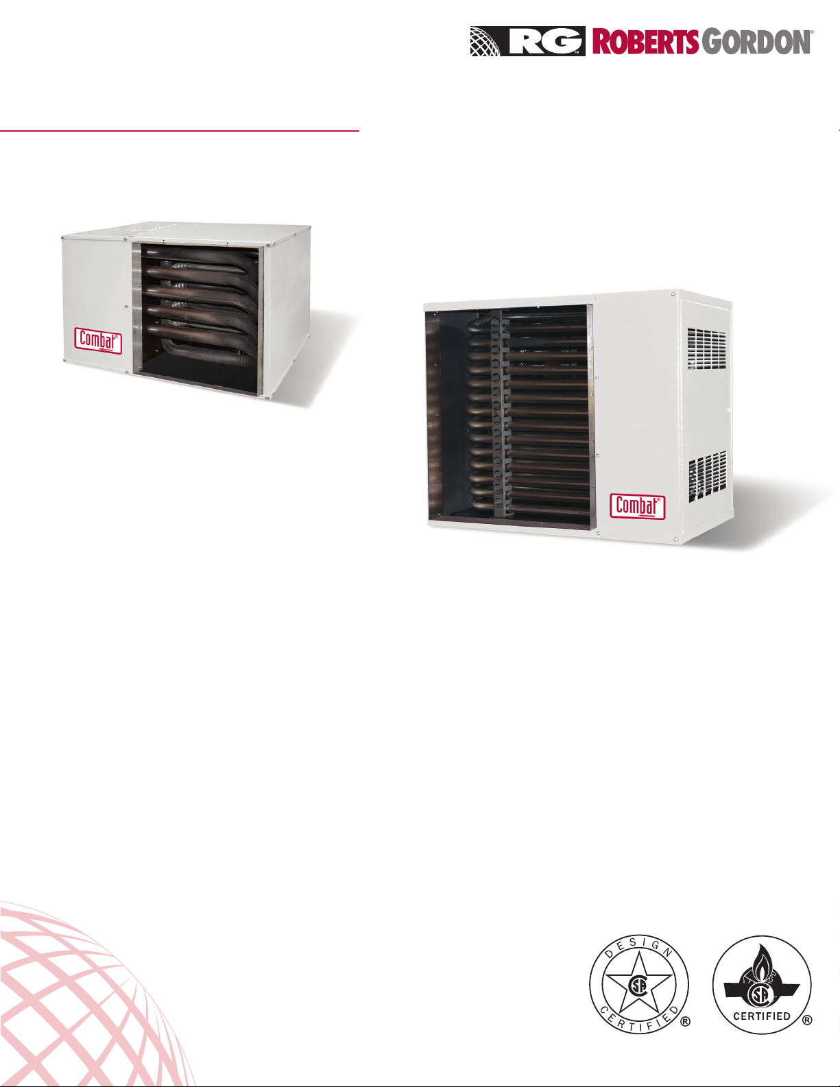
UHD[S] - Series
Tubular Duct Furnaces
t UHD[S] Models 75 - 125
UHD[S] Models 150 - 400 u
82% eciency with use of tubular heat
exchangers and inshot burners
Reliable ignition with direct spark ignition
burners.
Installation and operation exibility with rear
or top air and ue connections (Models UHD[S]
75 - 125 only).
Helps reduce dirt build-up on burners and helps
extend life of heat exchanger with separated
combustion units.
Longer life and less maintenance with optional
stainless steel heat exchangers.
Install downstream of refrigeration system with
option stainless steel heat exchangers and drain
pan (Models UHD[S] 150-400 only).
1.800.828.7450
www.rg-inc.com
Quality in Any Language
TM
Page 2
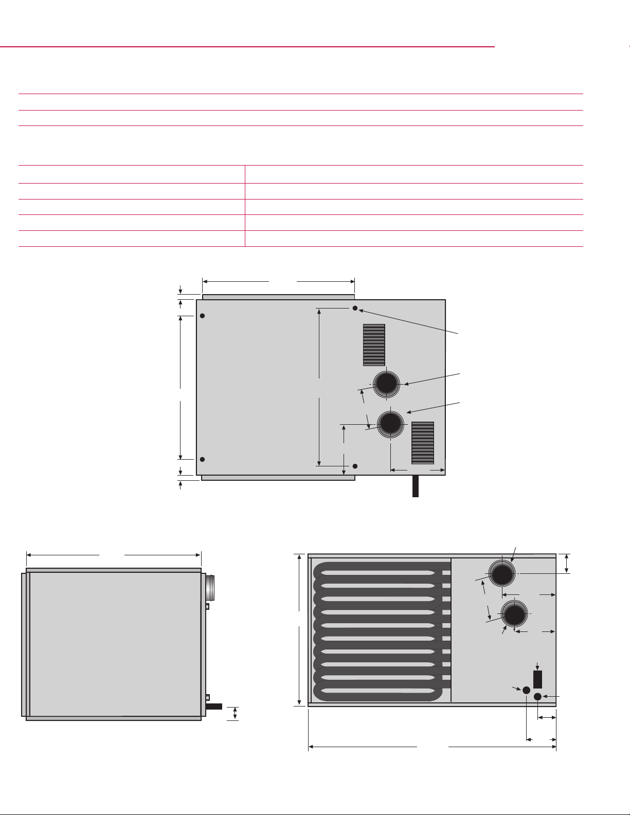
Combat® UHD[S] 75 - UHD[S] 125 Clearances and Dimension Data
B
20.25”
1.8”
A
D
Flue
28.5”
1.5”
3.3”
4 x 3/8” Captive Nuts Provided
16.63"
B
17.63"
Rear View
Top View
Gas Supply
6.75”
Air Intake
(UHDS only)
Side View
C
Air Intake
(UHDS only; Optional Position)
Flue
(Optional Position)
18.25”
Electrical
Supply
Thermostat
Connection
6"
6.75”
6 ”
6”
Clearances to Combustibles - Low Prole UHD[S] Range (Models 75 - 125)
Above Heater Below Heater To Side of Heater Access Side Door To Flue
1" 1" 1" 18" Access Clearance 2"
Dimension Data -
Model 75 100 125
'A' Height [in] 17.75 23 23
'B' Duct Connectors [in] 1.25 1.25 1.25
'C' Center of Flue [Top Option] [in] 5.2 6.9 6.9
'D' Center of Flue [in] 2.5 2.5 2.5
Low-Prole UHD[S] Range (Models 75 - 125)
Page 3

Combat® UHD[S] 150 - UHD[S] 400 Clearances and Dimension Data
K
B
C
25.5”
A
J
2.4”
6.5”
4 x 3/8” Captive Nuts Provided
C
F
D
19.4”
Support
Centers
Rear View
End View
G
H
Top View
Heater must be supported
at these points from above
or below.
Electrical
Supply
Air Intake
(UHDS only)
Flue
Thermostat
Connection
Gas
Supply
Clearances to Combustibles - Low Prole UHD[S] Range (Models 75 - 125)
Above Heater Below Heater To Side of Heater Access Side Door To Flue
6" 6" 6" 31" Access Clearance 2"
Dimension Data -
Standard UHD[S] Range (Models 150 - 400)
Model 150 175 200 225 250 300 350 400
'A' Width [in] 43 43 43 43 43 50 50 50
'B' Height [in] 27 27 35.25 35.25 35.25 43.5 43.5 43.5
'C' Duct Connectors [in] 1.25 1.25 1.25 1.25 1.25 1.25 1.25 1.25
'D' Support Spacing [in] 17.6 17.6 17.6 17.6 17.6 24.7 24.7 24.7
'F' Center of Flue [in] 9.5 9.5 17 17 17 13.6 13.6 13.6
'G' Flue Center to
Air Intake Center [in]
6 6 6 6 6 7 7 7
'H' Position of Flue [in] 4.5 4.5 4.75 4.75 4.75 4.9 4.9 4.9
'J' Gas Inlet Position [in] 5.9 5.9 5.9 5.9 5.9 8.7 8.7 8.7
'K' Electrical Supply Position [in] 3.4 3.4 3.4 3.4 3.4 6.2 6.2 6.2
Page 4

Combat® UHD[S]-Series Technical Data
Model 75 100 125 150 175 200 225 250 300 350 400
Total Input [Btu/h] x [1000]
Total Output [Btu/h] x [1000]
Eciency
Number of Burners 5 6 7 7 8 9 10 11 12 14 14
Gas Connection [in] ½ ½ ½ ½ ½ ½ ¾ ¾ ¾ ¾ ¾
Inlet Pressure [in wc] NG Min. 5
LPG Propane Min. 12
NG & LPG Propane Max. 14
Electrical Supply 115 V / 60 Hz / 1 Ø - All Models
Minimum Air Volume [CFM]
Temperature Rise @
Minimum Air Volume [°F]
Heat Exchanger Pressure Drop
@ Minimum Air Volume [in wc]
Maximum Air Volume [CFM] 2650 3660 4750 5800 6850 7750 8300 8850 10200 13600 14200
Temperature Rise @
Maximum Air Volume [°F]
Heat Exchanger Pressure Drop
@ Maximum Air Volume [in wc]
Flue Size [in] 4 - All Models
Air Intake [in] 4 4 4 4 4 4 4 4 5 5 5
Weight [lb] 81 92 97 191 211 239 249 254 325 345 345
75 100 125 150 175 200 225 250 300 350 385
61.5 82 102.5 123 143.5 164 184.5 205 246 288.6 315.7
82% - All Models
850 950 1020 1360 1400 2050 2100 2350 2700 3120 3420
68 78 92 83 95 73 80 80 86 86 86
0.06 0.05 0.06 0.02 0.03 0.025 0.035 0.05 0.02 0.03 0.04
22 22 20 20 20 20 20 22 23 22 22
0.36 0.55 0.98 0.16 0.29 0.163 0.253 0.35 0.27 0.48 0.53
Installation Code and Annual Inspections:
All installations and service of ROBERTS GORDON® equipment must be performed by a contractor qualified in the installation and
service of equipment sold and supplied by Roberts-Gordon and conform to all requirements set forth in the ROBERTS GORDON®
manuals and all applicable governmental authorities pertaining to the installation, service and operation of the equipment. To help facilitate
optimum performance and safety, Roberts-Gordon recommends that a qualified contractor annually inspect your ROBERTS GORDON®
equipment and perform service where necessary, using only replacement parts sold and supplied by Roberts-Gordon.
Further Information: Applications, engineering and detailed guidance on systems design, installation and equipment performance is avail-
able through ROBERTS GORDON® representatives. Please contact us for any further information you may require, including the Installation,
Operation and Service Manual.
This product is not for residential use.
This document is intended to assist licensed professionals in the exercise of their professional judgement.
Roberts-Gordon LLC
1250 William Street
P.O. Box 44
Bualo, NY 14240-0044 USA
European Oce:
Roberts Gordon Europe Limited
Telephone: +44(0) 121 506 7700
Fax: +44(0) 121 506 7701
Telephone: 716.852.4400
Fax: 716.852.0854
Toll Free: 800.828.7450
www.rg-inc.com
© 2008 Roberts-Gordon LLC All rights reserved. No part of this work covered by the copyrights herein may be reproduced or copied in any form or
by any means – graphic, electronic, or mechanical, including photocopying, recording, taping, or information storage
and retrieval systems – without written permission of Roberts-Gordon LLC.
Printed in U.S.A. UHDSNA 5M 0308 Orig.
 Loading...