

Page 1
WARNING
Installation must be done by a contractor qualified
in the installation and service of gas-fired heating
equipment or your gas supplier.
Improper installation, adjustment, alteration, service
or maintenance can result in death, injury or
property damage. Read the Installation, Operation
and Service Manual thoroughly before installing or
servicing this equipment.
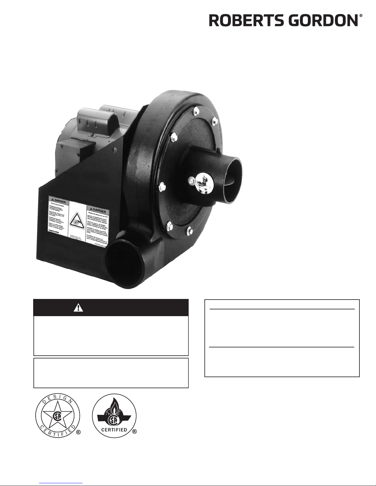
EP-200 Series
Pump
Installation,
Operation &
Service Manual
© 2018 Roberts-Gordon LLC
Installer
Please take the time to read and understand
these instructions prior to any installation.
Installer must give a copy of this manual to the owner.
Owner
Keep this manual in a safe place in order to provide
your service technician with necessary information.
Roberts-Gordon LLC
1250 William Street
P. O . B o x 4 4
Buffalo, New York 14240-0044
Telephone: +1.716.852.4400
Fax: +1.716.852.0854
Toll Free: 800.828.7450
www.robertsgordon.com
P/N 127200NA Rev. M 3/18
Page 2

Page 3

© 2018
Roberts-Gordon LLC
All rights reserved. No part of this work covered by the copyrights herein may be reproduced
or copied in any form or by any means - graphic, electronic, or mechanical, including
photocopying, recording, taping or information storage and retrieval systems - without the
written permission of Roberts-Gordon LLC.
TABLE OF CONTENTS
SECTION 1: Heating System Safety ............................1
1.1 Manpower Requirements ....................................1
1.2 Safety Labels and Their Placement ....................1
1.3 California Proposition 65 .....................................1
SECTION 2: Installer Responsibility............................3
2.1 Corrosive Chemicals...........................................3
2.2 National Standards and Applicable Codes .........3
SECTION 3: Unpacking the Pump ...............................4
3.1 Open Shipping Cartons ......................................4
SECTION 4: Major Components ..................................5
4.1 Standard Parts List .............................................6
SECTION 5: Pump Installation .....................................8
5.1 Pump Assembly Instructions ..............................8
SECTION 6: Pressure Switch Mounting and Wiring.12
6.1 Pressure Switch Installation..............................12
SECTION 7: Pump Mounting Instructions ................13
7.1 Wall Mounting....................................................13
7. 2 M o unting Platform
(Optional Platform Assembly) ............................14
SECTION 8: Motor Wiring ...........................................15
8.1 Impeller Rotation Direction ...............................15
8.2 EP-201 Wiring...................................................15
8.3 EP-203 Wiring...................................................15
SECTION 9: Venting....................................................16
9.1 General Venting Requirements.........................16
9.2 Venting the Pump .............................................16
9.3 Vent Material Recommendations ......................16
9.4 Horizontal Venting.............................................16
9.5 Vertical Venting.................................................18
9.6 Condensate Trap and Condensate Tee ............19
SECTION 10: Servicing Instructions .........................21
10.1 Pre-Season Maintenance and Annual
Inspection .......................................................21
10.2 To Change the Motor and/or the Impeller .......21
10.3 Maintenance Checklist....................................23
SECTION 11: Replacement Parts and Accessories .24
11.1 Replacement Parts ..........................................24
11.2 Accessories .....................................................24
SECTION 12: Specifications.......................................26
12.1 Material Specifications ....................................26
12.2 Suspension Specifications..............................26
12.3 Controls Specifications ...................................26
SECTION 13: The ROBERTS GORDON
®
EP-200 Series
Pump Warranty ........................................................... 27
Printed in U.S.A.
Page 4

Page 5

TABLE OF FIGURES
LIST OF TABLES
Table 1: EP-201 Pump Package (P/N 02716305) ..........6
Table 2: EP-203 Pump Package (P/N 02712034) ..........7
Figure 1: Label Placement ..............................................2
Figure 2: Major Component Descriptions ........................5
Figure 3: Pump Discharge Orientation /
Impeller Rotation Direction ..............................9
Figure 4: Pump Assembly .............................................10
Figure 5: Motor Shaft Seal Assembly ............................ 11
Figure 6: Pressure Switch Mounting Holes ...................12
Figure 7: Mounted Pressure Switch..............................12
Figure 8: Pump Pressure Switch Wiring ........................12
Figure 9: Wall Bracket Assembly...................................13
Figure 10: Wall Mounting Angle Assembly....................13
Figure 11: Wall Mounting............................................... 14
Figure 12: Mounting Platform Assembly .......................14
Figure 13: Side Wall Venting .........................................17
Figure 14: Vertical Venting ............................................18
Figure 15: Condensate Check Valve ............................. 18
Figure 16: Condensate Tee - Discharge Side................19
Figure 17: Condensate Neutralization Tube ..................20
Page 6

Page 7

SECTION 1: HEATING SYSTE M SAFETY
SECTION 1: HEATING SYSTEM SAFETY
Yo ur Safety is Important to Us!
This symbol is used throughout
the manual to notify you of
possible fire, electrical or burn
hazards. Please pay special
attention when reading and
following the warnings in these
sections.
Installation, service and annual inspection of heater
and pump must be done by a contractor qualified in
the installation and service of gas-fired heating
equipment.
Read this manual carefully before installation,
operation or service of this equipment.
CTHN multiburner and CRVB systems are designed
for heating nonresidential indoor spaces. Model
CRVSF is for nonresidential indoor spaces where
exposed surfaces of heating equipment cannot
exceed temperatures of 750 °F (399 °C) in facilities
where compressed natural gas (CNG) or liquid
natural gas (LNG) are present. Do not install in
residential spaces. These instructions, the layout
drawing, local codes and ordinances, and applicable
standards that apply to electrical wiring, venting, etc.
must be thoroughly
understood before proceeding
with the installation.
Protective gear is to be worn during installation,
operation and service in accordance to the
Occupational Safety and Hazard Administration
(OSHA). Gear must be in accordance to NFPA 70E,
latest revision when working with electrical
components. Thin sheet metal parts, such as various
venting components, have sharp edges. To prevent
injury, the use of work gloves is recommended.
Do not attempt to operate the pump until all steps of
the installation have been accomplished.
This pump must be applied and operated under the
general concepts of reasonable use and installed
using best building practices.
This equipment is not intended for use by persons
(including children) with reduced physical, sensory or
mental capabilities, or lack of experience and knowl-
edge, unless they have been given supervision or
instru
ction concerning use of the appliance by a person responsible for their safety. Children should be
supervised to ensure that they do not play with the
equipment.
1.1 Manpower Requirements
To p r event personal injury and damage to the pump,
two persons will be required for installation.
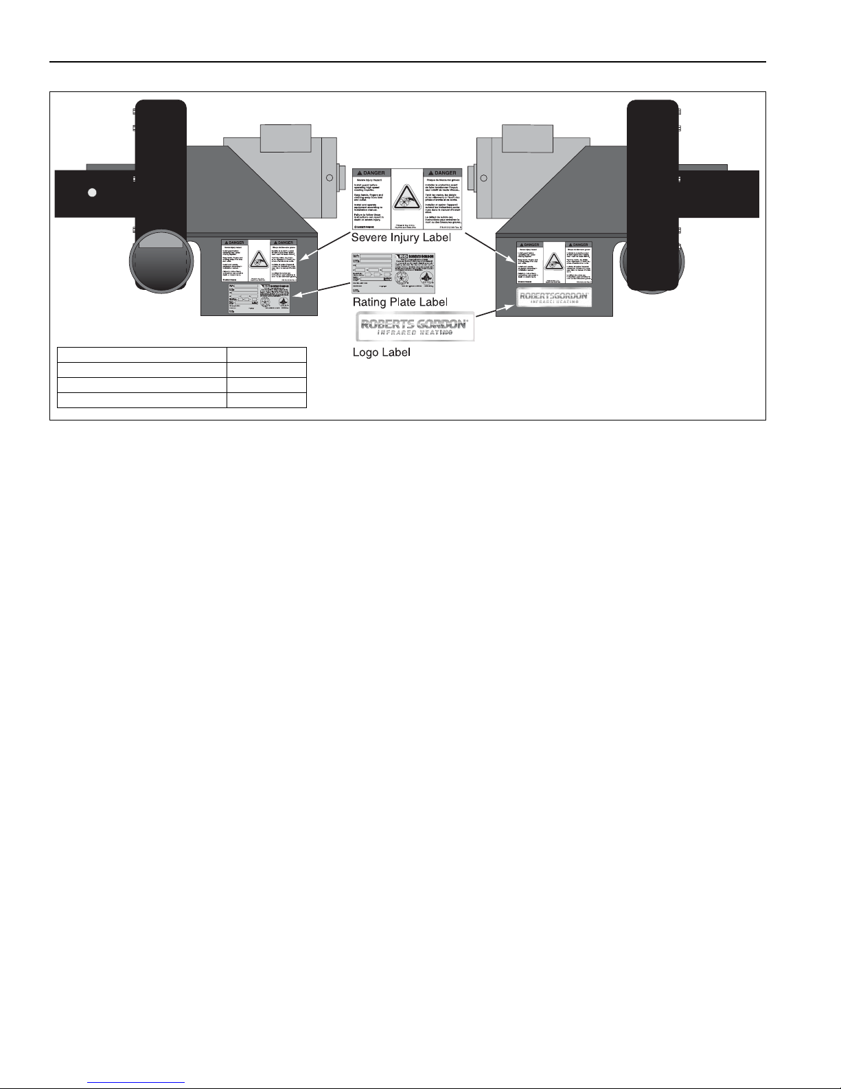
1.2 Safety Labels and Their Placement
Product safety signs or labels should be replaced by
the product user when they are no longer legible.
Please contact Roberts-Gordon LLC or your
ROBERTS GORDON
®
independent distributor to
obtain replacement signs or labels. See Page 2,
Figure 1.
1.3 California Proposition 65
In accordance with California Proposition 65 require-
ments, a warning label must be placed in a highly
visible location on the outside of the equipment (i.e.,
near equipment’s serial plate). See the heaters’
Installation, Operation and Service Manual for label
placement. Avoid placing label on areas with extreme
heat, cold, corrosive chemicals or other elements. To
order additional labels, please contact Roberts-Gordon LLC or your ROBERTS GORDON
®
indepen-
dent distributor.
For additional copies of the Installation, Operation
and Service Manual, please contact Roberts-Gordon
LLC.
1 of 27
Page 8
EP-200 SERIES PUMP INSTALLATION, OPERATION AND SERVICE MANUAL
Description Part Number
Severe Injury Label 91012100
Rating Plate Label 91010401
Logo Label 91017200
FIGURE 1: Label Placement
2 of 27
Page 9
SECTION 2: INSTALLER R ESPONSIBILITY
CAUTION
Product Damage Hazard
Do not use heater in area containing
corrosive chemicals.
Refer to appropriate Material Safety Data
Sheets (MSDS).
Failure to follow these instructions can result
in product damage.
SECTION 2: INSTALLER RESPONSIBILITY
The installer is responsible for the following:
• To install the pump and electrical supplies, in
accordance with applicable specifications and
codes. Roberts-Gordon LLC recommends the
installer contact a local building inspector or fire
marshal for guidance.
• To use the information given in a layout drawing
and in the manual together with the cited codes
and regulations to perform the installation.
• To install the heater in accordance with the
clearances to combustibles.
• To furnish all needed materials not furnished as
standard equipment.
• To plan location of supports.
• To provide access to pump for servicing on all
sides and for pump removal.
• To provide the owner with a copy of this installation, operation and service manual.
• To never use pump or pump platform as support
for ladder or other access equipment and never
hang or suspend anything from pump or pump
platform.
• To safely and adequately install pump using
materials with a minimal working load of 750 lb
(340 kg).
• To ensure the heater is placed in an approved
application.
• For CRVSF-Series only: To install system with
a minimum of 18" (45 cm) ceiling clearance in
accordance to National Fire Protection Association NFPA 30A (2012 edition).
2.1 Corrosive Chemicals
Roberts-Gordon LLC cannot be responsible for
ensuring that all appropriate safety measures are
undertaken prior to installation; this is entirely the
responsibility of the installer. It is essential that the
contractor, the sub-contractor, or the owner
identifies the presence of combustible materials,
corrosive chemicals or halogenated hydrocarbons*
anywhere in the premises.
* Halogenated Hydrocarbons are a family of chemical compounds characterized by the presence of halogen elements
(fluorine, chlorine, bromine, etc.). These compounds are
frequently used in refrigerants, cleaning agents, solvents, etc.
If these compounds enter the air supply of the burner, the life
span of the heater components will be greatly reduced. An
outside air supply must be provided to the burners whenever
the presence of these compounds is suspected. Warranty will
be invalid if the heater is exposed to halogenated hydrocarbons.
2.2 National Standards and Applicable Codes
All Appliances must be installed in accordance with
the latest revision of the applicable standards and
national codes. This refers also to the electric, gas
and venting installation. Note: Additional standards
for installations in Public Garages, Aircraft Hangars,
etc. may be applicable.
3 of 27
Page 10
EP-200 SERIES PUMP INSTALLATION, OPERATION AND SERVICE MANUAL
WARNING
Cut/Pinch Hazard
Wear protective gear during installation,
operation and service.
Edges are sharp.
Failure to follow these instructions can result
in injury.
SECTION 3: UNPACKING THE PUMP
3.1 Open Shipping Cartons
Open cartons and remove packing inserts. Carefully
remove pump components from the cartons. Lift
assembly by gripping metal pump frame. Two people
are required (weight 112 lb, 51 kg). This pump has
been tested prior to packing. The impeller was
dynamically balanced before assembly and requires
care in handling to avoid damage.
4 of 27
Page 11
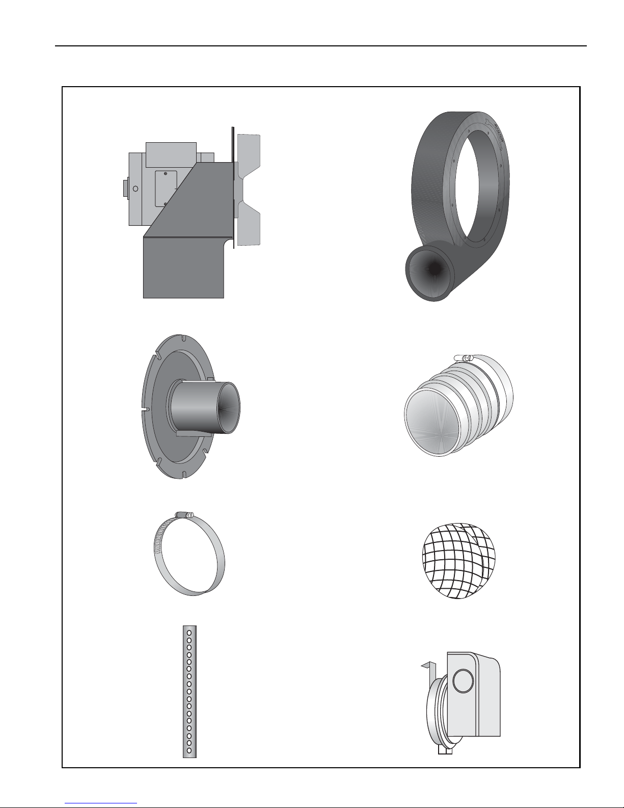
SECTION 4: MAJOR COMPONENTS
EP-201 Pump Assembly - 01312001
EP-203 Pump Assembly - 01312002
Pump Scroll Assembly - 01394401
Band Clamp 5" (13 cm) - 91901301
Bird Screen 4" (10 cm) - 01365400
Mounting Angle - 01365000
Flexible Boot 4.5" (11 cm) - 91412801
Silicone Rubber Ring - 91906900
Pump Inlet Assembly - 01327400
Pressure Switch - 90430600K
SECTION 4: MAJOR COMPONENTS
FIGURE 2: Major Component Descriptions
5 of 27
Page 12

EP-200 SERIES PUMP INSTALLATION, OPERATION AND SERVICE MANUAL
4.1 Standard Parts List
Table 1: EP-201 Pump Package (P/N 02716305)
Part No. Description Quantity
Box 1 of 2
01312001 EP-201 Pump Assembly Includes: 1
127102NA
CORAYVAC
® Installation, Operation and Service Manual
127200NA EP-200 Series Installation, Operation and Service Manual
Box 2 of 2
01317805 EP-200 Pump Accessory Package Includes: 1
01327500 Inlet Plate Assembly 1
01329500 Damper Support Assembly 1
01365400 Bird Screen, 4" 1
01365000 Mounting Angle 6
01394401 Pump Scroll 1
01394502 Inlet Casting 1
02757500 Motor Shaft Seal 1
91312600 Sleaving 1
91406940 Pump Gaskets 4
93413008 Bolt (1/4" - 20" x 1/2") 1
127200NA EP-200 Series Installation, Operation and Service Manual 1
01311700 EP-200 Pump Accessory Kit Includes: 1
91901301 Band Clamp, 5" (13 cm) 4
92113900 Hex Nut 6
93413912 Bolt (5/16" -18" x 3/4") 6
94273914 Bolt (5/16" -18" x 7/8") 16
95211600 Flat Washer (5/16") 28
96411600 Lockwasher (5/16") 6
91412801 4.5" Flexible Boot 2
91906900 Silicone Rubber Ring 2
90430600K Pressure Switch Kit Includes: 1
90430600 Pressure Switch 1
91417409 Silicone Hose 1
91220201 Barbed Fitting 1
91104001 Locknut 2
94118106
96211000
93511706
92311800
Screw
Lock Washer
Screw
Locknut
#
8 x 3/8
#
10
#
10-32 x 3/8
#
10-32
91700015 Instructions 1
®
127302NA
CORAYVAC
CRVSF burner carton)
Classic SF Installation, Operation and Service Manual (Included in
1
2
2
2
2
6 of 27
Page 13

SECTION 4: MAJOR COMPONENTS
Table 2: EP-203 Pump Package (P/N 02712034)
Part No. Description Quantity
Box 1 of 2
01312002 EP-203 Pump Assembly Includes: 1
127102NA
CORAYVAC
Box 2 of 2
01317805 EP-200 Pump Accessory Package Includes: 1
01327500 Inlet Plate Assembly 1
01329500 Damper Support Assembly 1
01365400 Bird Screen, 4" 1
01365000 Mounting Angle 6
01394401 Pump Scroll 1
01394502 Inlet Casting 1
02757500 Motor Shaft Seal 1
91312600 Sleaving 1
91406940 Pump Gaskets 4
93413008 Bolt (1/4" - 20" x 1/2") 1
127200NA EP-200 Series Installation, Operation and Service Manual 1
01311700 EP-200 Pump Accessory Kit Includes: 1
91901301 Band Clamp, 5" (13 cm) 4
92113900 Hex Nut 6
93413912 Bolt (5/16" -18" x 3/4") 6
94273914 Bolt (5/16" -18" x 7/8") 16
95211600 Flat Washer (5/16") 28
96411600 Lockwasher (5/16") 6
91412801 4.5" Flexible Boot 2
91906900 Silicone Rubber Ring 2
90430600K Pressure Switch Kit Includes: 1
90430600 Pressure Switch 1
91417409 Silicone Hose 1
91220201 Barbed Fitting 1
91104001 Locknut 2
94118106
96211000
93511706
92311800
Screw
Lock Washer
Screw
Locknut
91700015 Instructions 1
127302NA
CORAYVAC
CRVSF burner carton)
®
Installation, Operation and Service Manual
#
8 x 3/8
#
10
#
10-32 x 3/8
#
10-32
®
Classic SF Installation, Operation and Service Manual (Included in
1
2
2
2
2
7 of 27
Page 14
EP-200 SERIES PUMP INSTALLATION, OPERATION AND SERVICE MANUAL
SECTION 5: PUMP INSTALLATION
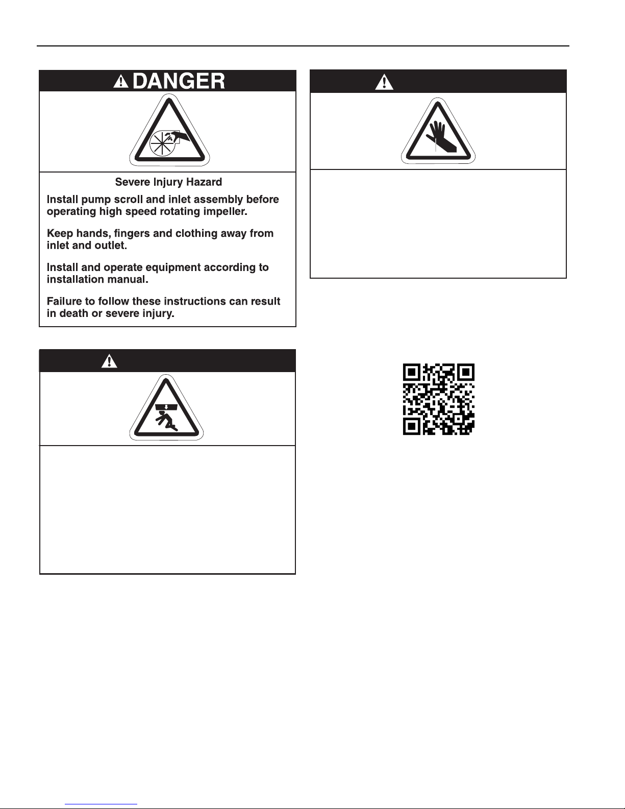
WARNING
Cut/Pinch Hazard
Wear protective gear during installation,
operation and service.
Edges are sharp.
Failure to follow these instructions can result
in injury.
NOTE: Installers may also visit Roberts-Gordon
Yo uTube page to view pump assembly video at
https://www.youtube.com/watch?v=F-u8xtvaAZ8
or scan the QR code below:
WARNING
Severe Injury Hazard
Secure pump to tube.
Hang pump with materials with a minimum
working load of 750 lbs (340 kg).
Failure to follow these instructions can result
in death, injury or property damage.
5.1 Pump Assembly Instructions
5.1.1 Determine Orientation of Pump Discharge
To e n s ure your safety, and comply with the terms of
the warranty, all units must be installed in accordance with these instructions.
The pump must be installed in a location that it is
readily accessible for servicing.
For CRVSF-Series only, a minimum of 18" (45 cm)
ceiling clearance in accordance to National Fire Protection Association (NFPA) 30A latest revision is
required.
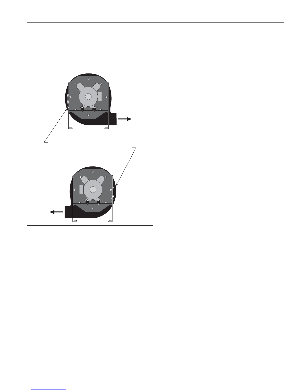
An arrow is affixed to the outside of the pump scroll to
indicate the direction of rotation of the impeller. The
standard rotation of the impeller is in the counterclockwise direction.
8 of 27
Pump discharge orientation and impeller rotation
direction is viewed from the rear of the motor as
shown on Page 9, Figure 3. Note that the pump scroll
outlet must always be positioned at the bottom hori-
Page 15
SECTION 5: PUMP INSTALLATION
Arrow showing direction of rotation
(located on front of scroll housing)
Counterclockwise Rotation
(Standard)
OUTLET
Clockwise Rotation
OUTLET
zontal position.
FIGURE 3: Pump Discharge Orientation /
Impeller Rotation Direction
quate clearance is maintained between the impeller blades and the body of the pump scroll.
5.1.2 Attaching Pump Scroll
After determining the correct orientation of the pump
scroll outlet, attach the pump scroll to the pump
frame as follows:
• Place Flat Washer (P/N 95211600), on the 5/16" x
7/8" Screw (P/N 94273914).
• From the motor side of the vertical mounting plate
of the pump frame, insert the 5/16" x 7/8" screws.
• Install two pieces of the gasket material on the
exposed thread ends of the mounting screws.
Make sure the ends of the opposing gasket segments interlock to form a complete circular
gasket.
• Carefully position the pump scroll against the ver-
tical mounting plate of the pump frame; align and
loosely install the 5/16" x 7/8" screws into the corresponding mounting holes in the pump scroll.
• While tightening the screws (torque to 132 in/lb)
that secure the pump scroll to the motor frame,
periodically spin the impeller to be sure that ade-
9 of 27
Page 16
EP-200 SERIES PUMP INSTALLATION, OPERATION AND SERVICE MANUAL
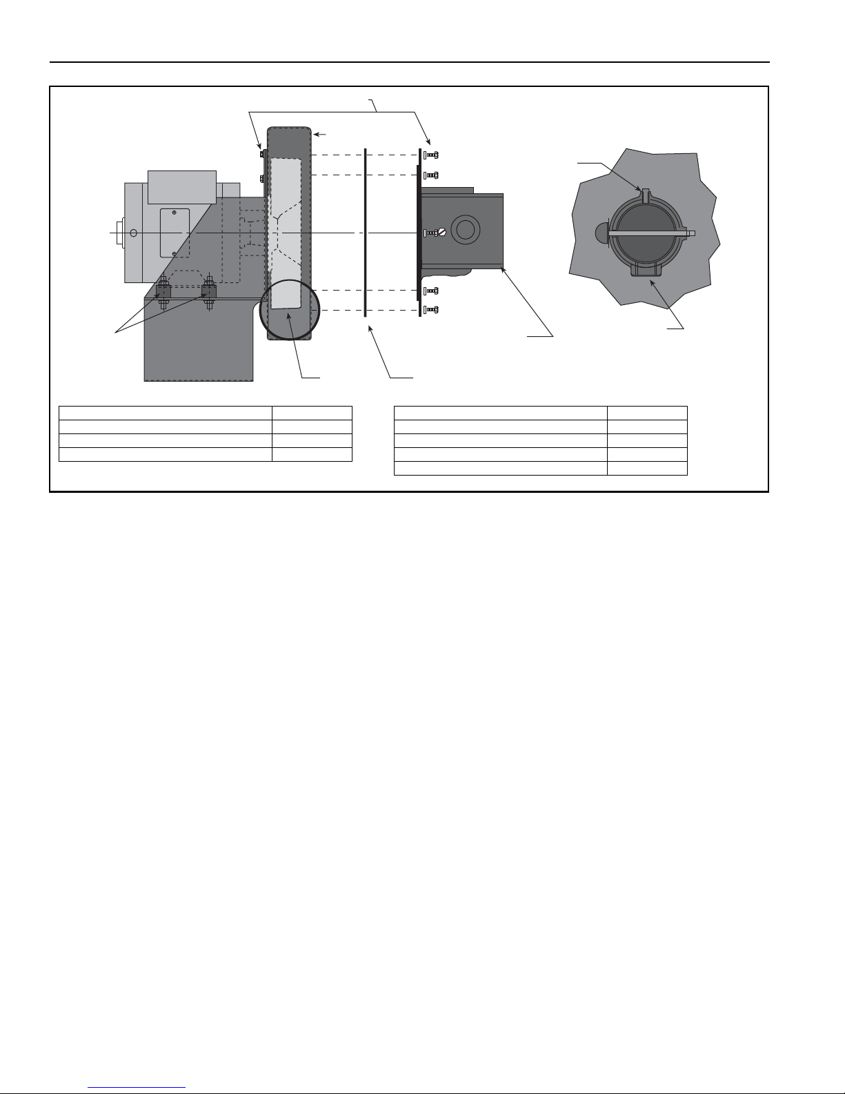
Inlet Plate Assembly
Impeller
Pump Scroll
Gasket (2 pieces)
Partial End View
1" NPT
Rubber
Mounts
5/16 x 7/8" Screws (w/flat washers) - 16 Req'd.
1/8" NPT
Description Part Number
Pump Scroll 01394401
Rubber Mounts 91906100
Impeller 01394602
Description Part Number
Inlet Plate Assembly Kit 01327400
Gaskets (2) 91406940
Inlet Plate 01327400
Accessory Bag (8 bolts, 8 flat washers) 01311702
FIGURE 4: Pump Assembly
5.1.3 Attaching Pump Inlet Assembly
From scroll assembly side of pump, orient inlet
assembly so threaded pipe coupling is on top. See
partial end view on Page 10, Figure 4.
• Place flat washer on the 5/16" x 7/8" screw.
• Position a single section of gasket against face of
pump scroll; align clearance holes of gasket with
mounting holes of pump scroll. Loosely install one
5/16" x 7/8" screw through gasket segment and
into top center mounting hole of pump scroll to
support gasket.
• Interlock remaining gasket segment to previously
installed gasket segment to complete circular
gasket.
• Orient inlet plate assembly as shown. The
1/8" NPT plug should face directly up, and 1" NPT
plug should face directly downward. Carefully
position top center mounting notch of inlet plate
assembly to engage mounting screw positioned
previously.
• Install seven remaining 5/16" x 7/8" screws
through notches in inlet plate assembly and into
corresponding mounting holes in p
• Tighten screws (torque to 132 in/lb) to complete
installation of inlet plate assembly.
10 of 27
ump scroll.
• Install pressure switch in 1/8" NPT hole in top of
outlet.
Page 17
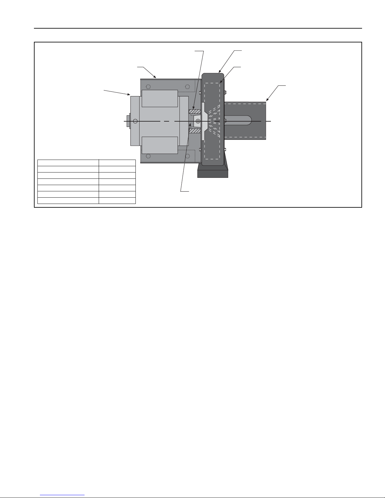
FIGURE 5: Motor Shaft Seal Assembly
Motor Shaft Seal
EP-201 Motor
or
EP-203 Motor
Pump Frame
Motor Shaft Hub
Impeller
Inlet Plate Assembly
Pump Scroll
Description Part Number
EP-201 Motor 90604500
EP-203 Motor 90604501
Motor Shaft Seal 02757500
Pump Scroll 01394401
Impeller 01394602
Inlet Plate Assembly 01327400
SECTION 5: PUMP INSTALLATION
5.1.4 Installing Motor Shaft Seal
Motor shaft seal (P/N 02757500) eliminates air leakage around motor shaft and reduces associated
noise. Install shaft seal as follows:
1. Separate motor shaft seal at pre-cut score line.
2. Wrap shaft seal around motor shaft hub as
shown on Page 11, Figure 5.
3. Secure shaft seal in position with adhesive strip
provided.
11 o f 2 7
Page 18
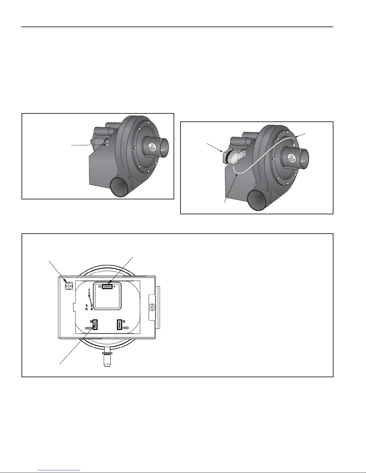
EP-200 SERIES PUMP INSTALLATION, OPERATION AND SERVICE MANUAL
Pressure Switch
Mounting Holes
(located on both
sides of pump frame)
Barbed
Fitting
Silicone Hose
Pressure Switch
Ground Screw
Common Terminal
Normally Open Terminal
Connect wire leads provided to terminals 1 and 2
labeled (C) Common and (NO) Normally Open. Refer
to pressure switch kit installation instructions or control panel installation instructions for connection to
controls.
SECTION 6: PRESSURE SWITCH MOUNTING AND WIRING
6.1 Pressure Switch Installation
For connection to a pump, locate the two pressure
switch mounting holes on the pump frame. If replac-
ing an old pressure switch, you may need to drill two
holes in the pump frame (7/32" dia. approximately
13/16" apart).
6.1.1 Attaching Pressure Switch to Pump Inlet
Using screws and locknuts included, mount the
switch to the pump frame. Thread the barbed fitting
into the threaded hole at the pump inlet. Cut the
silicone tube to the appropriate length to eliminate
the possibility of kinks and securely attach the hose
to the pressure switch and the barbed fitting.
FIGURE 6: Pressure Switch Mounting Holes
FIGURE 7: Mounted Pressure Switch
FIGURE 8: Pump Pressure Switch Wiring
12 of 27
Page 19
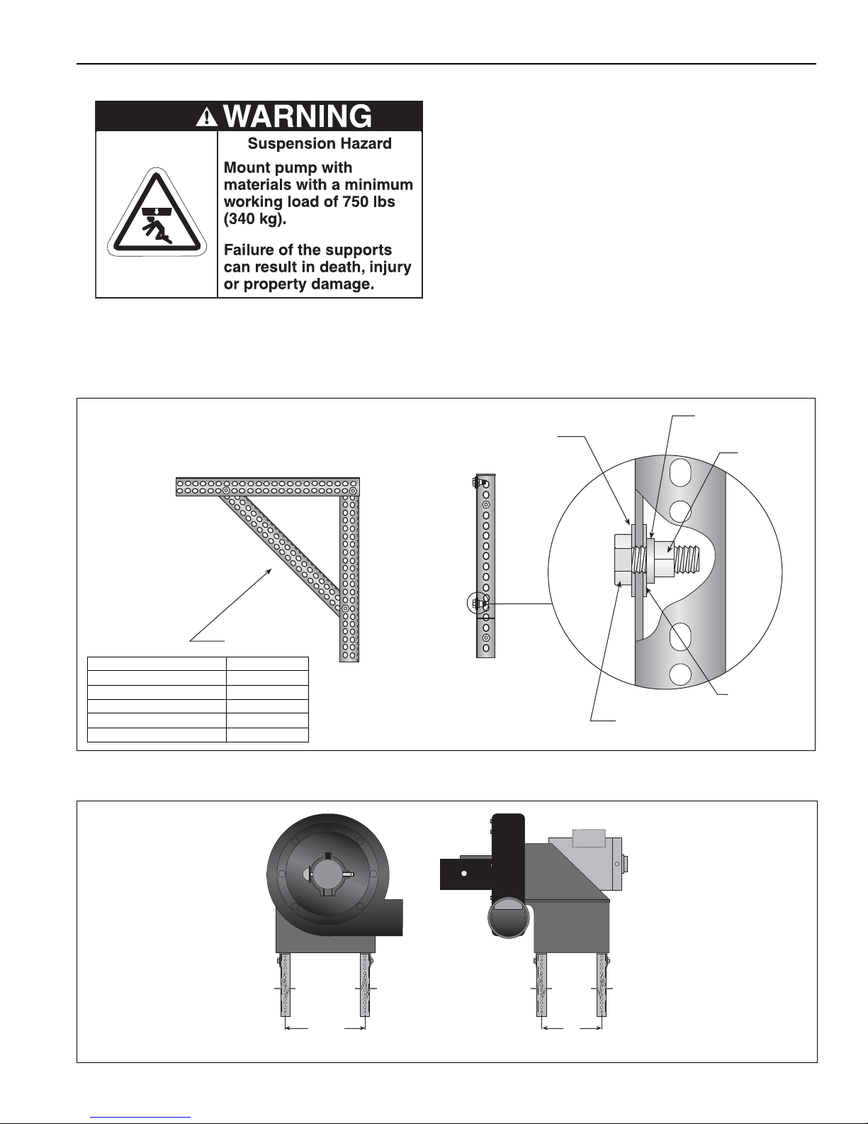
SECTION 7: PUMP MOUNTING INSTRUCTIONS 7.1 Wall Mounting
Mounting
Angle
Hex Bolt
Flat Washer
Lockwasher
Hex Nut
Flat Washer
Description Part Number
Mounting Angle 01365000
Hex Bolt 5/16" x 3/4" 93413912
Flat Washer 95211600
Lockwasher 96411600
Hex Nut 92113900
NOTE: Typical assembly shown.
Two (2) assemblies per
each pump required.
7"
(178 mm)
11.5"
(292 mm)
The standard method of mounting the EP-200 pump
is on an outside wall and venting directly through the
wall.
The pump may be mounted by using mounting
angles as shown in Figure 9. The two mounting
angles form a mounting platform to which the pump
will be attached.
Attach the mounting frame to the wall using anchors.
Select an anchor that will give equal to or greater
than 2000 lb ultimate pull-out strength.
For CRVSF-Series only, a minimum of 18" ceiling
clearance in accordance to National Fire Protection
Association (NFPA) 30A latest revision is required.
FIGURE 9: Wall Bracket Assembly
SECTION 7: PUMP MOUNTING I NSTRUCTIONS
FIGURE 10: Wall Mounting Angle Assembly
13 of 27
Page 20
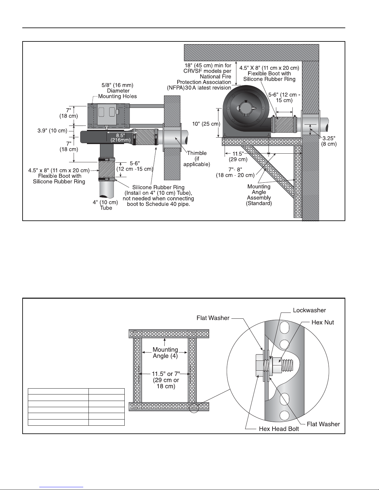
EP-200 SERIES PUMP INSTALLATION, OPERATION AND SERVICE MANUAL
Description Part Number
Mounting Angle 01365000
Hex Bolt 5/16" x 3/4" 93413912
Flat Washer 95211600
Lockwasher 96411600
Hex Nut 92113900
FIGURE 11: Wall Mounting
7.2 Mounting Platform (Optional Platform
Assembly)
If mounting on an outside wall is not practical, it may
be mounted on a platform suspended from the
ceiling, or for noise reduction, in an enclosure.
FIGURE 12: Mounting Platform Assembly
14 of 27
Page 21
SECTION 8: MOTOR WIRING
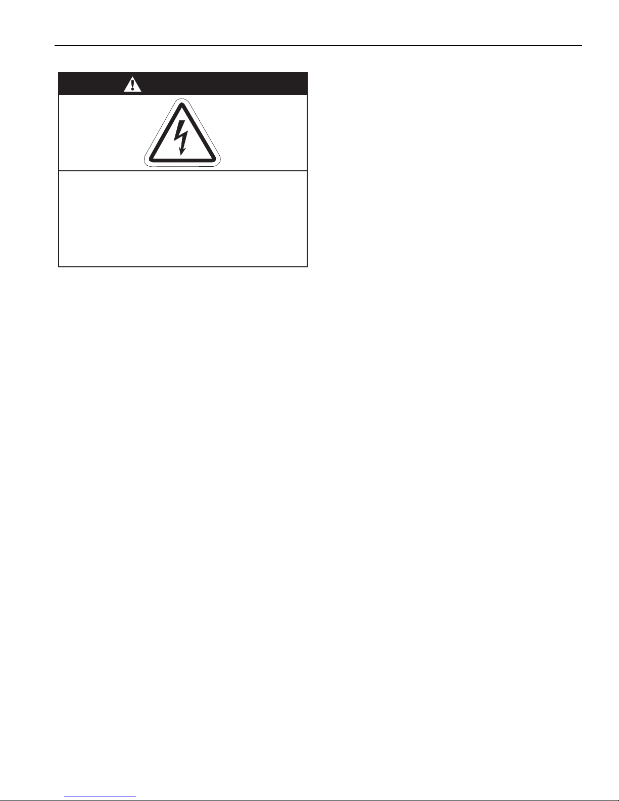
DANGER
Electrical Shock Hazard
Disconnect electric before service.
Appliance must be properly grounded.
Failure to follow these instructions can result
in death or electrical shock.
SECTION 8: MOTOR WIRING
All wiring must comply with current wiring regulations
and any local regulations which may apply. Always
switch off the supply and disconnect before servicing.
8.1 Impeller Rotation Direction
Prior to operation of the pump in the heating system,
operation and proper rotation of the impeller must be
verified. For reverse rotation, follow manufacturer's wir-
ing diagram located on motor.
The motor must be wired for clockwise or counter-
clockwise rotation.
IMPORTANT: Improper rotation of the impeller will
not produce the vacuum required for proper system
operation.
8.2 EP-201 Wiring
The EP-201 motor is wired for 1 Ø, 120 V, 60 Hz
operation. The EP-201 motor can be rewired for 230 V
operation by changing the motor connections as
indicated by the diagram on the motor. For proper
motor wiring, follow manufacturer's wiring diagram
located on motor.
When controlled by a CORAYVAC
®
Heating Control
use Contactor Package 17A (P/N 10050011). See
ROBERTS GORDON
®
CORAYVAC® Heating Control
Manual (P/N 10091601NA) wiring details.
Wire the pressure switch per th
ual (P/N 127102NA) for CRV models, CORAYVAC
e CORAYVAC® Man-
®
Classic SF (127302NA) for CRVSF models or VAN-
®
TAG E
CTHN (P/N 152101NA) Installation, Operation
and Service Manuals.
8.3 EP-203 Wiring
The EP-203 motor can be wired for 3 Ø, 208 V - 230
V, 60 Hz or 3 Ø, 460 V, 60 Hz operation.
The EP-203 motor rotation direction can be changed
by interchanging any two leads. For proper motor wir-
ing, follow manufacturer's wiring diagram located on
motor.
When controlled by a CORAYVAC
®
Heating Control
use Contactor Package 17A (P/N 10050011). See
Page 15, Figure . See ROBERTS GORDON
®
CORAYVAC® Heating Control Manual (P/N
10091601NA) wiring details.
Wire the pressure switch per the heaters’ Installation,
Operation and Service Manual or appropriate controller
installation manual.
15 of 27
Page 22
EP-200 SERIES PUMP INSTALLATION, OPERATION AND SERVICE MANUAL
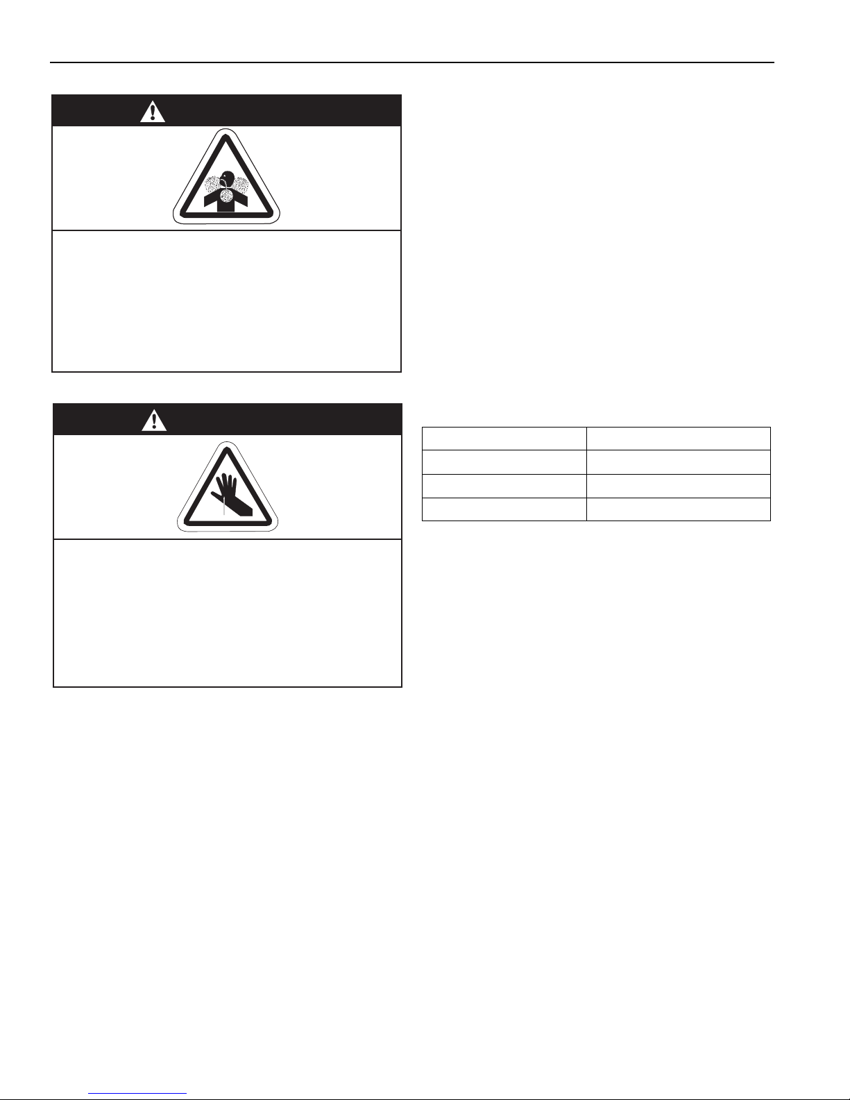
WARNING
Carbon Monoxide Hazard
Pump must be vented to the outside.
Heaters must be installed according to the
installation manual.
Failure to follow these instructions can result
in death or injury.
WARNING
Cut/Pinch Hazard
Wear protective gear during installation,
operation and service.
Edges are sharp.
Failure to follow these instructions can result
in injury.
SECTION 9: VENTING
9.2 Venting the Pump
• Exhaust connection from pump is 4.5" (11 cm)
diameter.
• Connect one of the flexible boots provided to the
4" (10 cm) flue pipe, using the silicone rubber ring
prov
ided.
• Connections to flue pipe larger than 4" (10 cm)
require use of an appropriate "taper pattern
reducer" (not supplied).
• Venting from pump may discharge either horizontally or vertically. Horizontal discharge is pre-
ferred. See Page 17, Figure 13. Vertical discharge
must be arranged as shown on Page 18, Figure
14. Corrosion resistant pipe is required.
• Both horizontal and vertical venting must be sup-
ported by suitable hangers.
• Vent lengths are allowed as follows:
VENT LENGTH VENT SIZE
Up To 10' (3 m) 4" (10 cm) vent - 1 elbow
9.1 General Venting Requirements
This pump must be vented in accordance with the
rules contained in this manual and with the following
national codes and any state, provincial or local
codes which may apply:
United States: Refer to National Fuel Gas Code
NFPA 54/ANSI Z223.1 - latest revision.
Canada: Refer to Natural Gas and Propane
Installation Code CSA B149.1 - latest revision.
This section provides partial information about this
specification with regard to size and configuration for
venting requirements. See Page 17, Figure 13 and
Page 18, Figure 14. However, to provide assurance
of proper and safe operation, it is the responsibility of
the installer to make sure the installation is in strict
accordance with all local and national codes.
Up To 25' (8 m) 5" (12.5 cm) vent - 3 elbow
Up To 50' (15 m) 6" (15 cm) vent - 3 elbow
9.3 Vent Material Recommendations
Vent recommendations:
1. Porcelain coated tubing 4" (10 cm) O.D. (P/N
9141030D)
2. Heat treated aluminized tubing 4" (10 cm) O.D.
(P/N 91409408)
Heat treated aluminized tubing 6" (15 cm) O.D.
(P/N E0009105)
3. Single wall flue pipe - minimum 26 ga.
(Not suitable for modulating and condensing
system designs)
4. Schedule 40 ASTM A53 (Latest Edition) grade B
ERW black steel pipe”
9.4 Horizontal Venting
Vent length be limited to less than 30' (9 m). If using
vent lengths greater than 30' (9 m), condensation will
form in the vent pipe. Insu
ing measures will be required. Seal all discharge pipe
joints with high temperature silicone adhesive.
• Vent must exit building not less than 7' (2 m)
above grade when located adjacent to public
walkways.
lation and additional seal-
16 of 27
Page 23
SECTION 9: VENTING
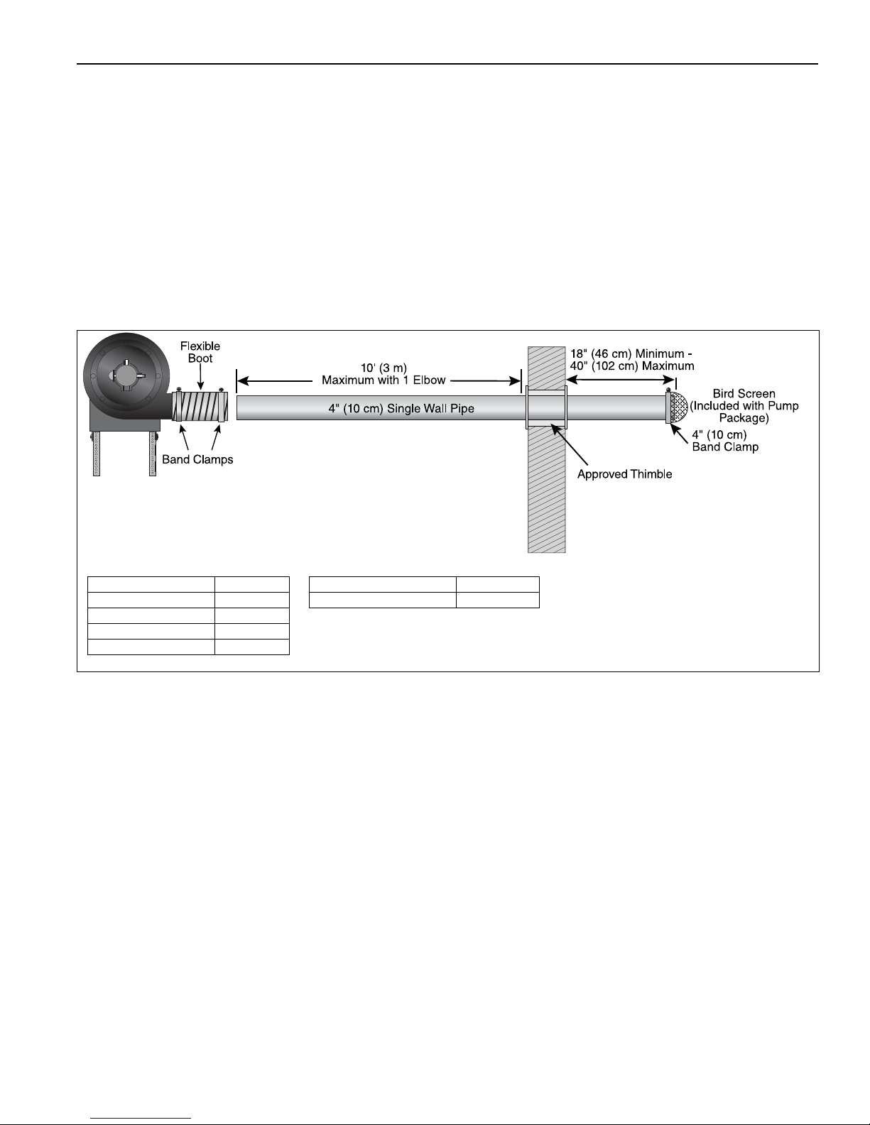
Description Part Number Description Part Number
Bird Screen 4'' (10 cm) 01365400 Flexible Boot, 4.5" (11 cm) 91412801
Bird Screen, 6'' (15 cm) 01397400
Band Clamp, 5'' (13 cm) 91901301
Band Clamp, 6'' (15 cm) 91913703
• Vent must terminate at least 3' (1 m) above any
forced air inlet located within 10' (3 m).
• Vent must terminate at least 4' (1.2 m) below 4'
(1.2 m) horizontally from or 12" (30 cm) above any
door, window or gravity air inlet into building.
• Locate vent terminal at least 12" (30 cm) from any
opening through which vent gases could enter a
building.
• Use only corrosion resistant materials for the
discharge line from the pump to the point of
discharge.
FIGURE 13: Side Wall Venting
• Vent terminal opening must extend beyond any
combustible overhang.
• Install vent terminal at a height sufficient to
prevent blockage by snow.
• Protect building materials from degradation by flue
gases.
• Any portion of flue pipe passing through a
combustible wall must be dual insulated and an
approved thimble must be used.
17 of 27
Page 24
EP-200 SERIES PUMP INSTALLATION, OPERATION AND SERVICE MANUAL
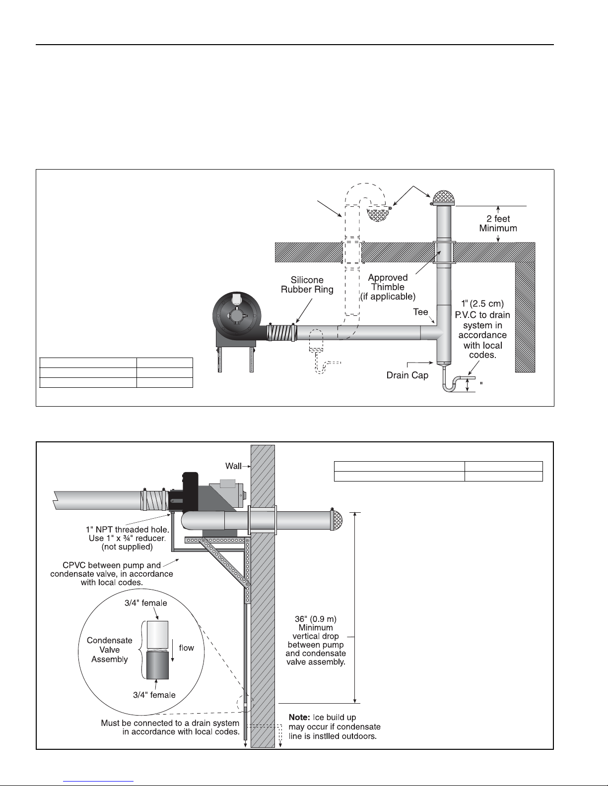
Description Part Number
Tee 4" (10 cm) 01330203
Drain Cap 4" (10 cm) 02718851
6 (15 cm)
Bird Screen
Optional
NOTE: Vacuum loss
may occur when
using vent caps.
The use of bird screen
to cover vent terminations
is recommended.
Description Part Number
Condensate Valve Assembly 01327001
9.5 Vertical Venting
Condensation will form in the vent pipe. Insulation
and additional sealing measures may be required.
Length of flue pipe is equal to total of vertical and
horizontal length. Seal all discharge pipe joints with
high temperature silicone adhesive. Vertical venting
for CRVSF systems is not recommended.
FIGURE 14: Vertical Venting
FIGURE 15: Condensate Check Valve
18 of 27
Page 25
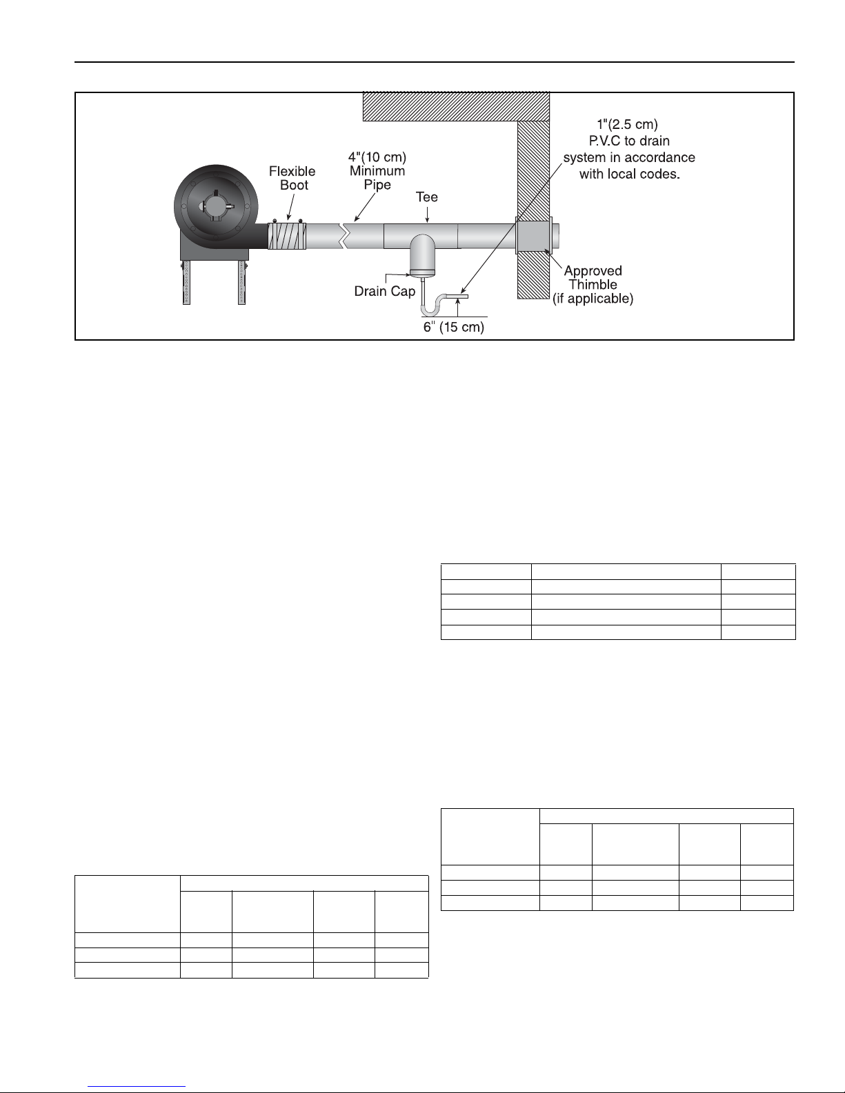
FIGURE 16: Condensate Tee - Discharge Side
SECTION 9: VENTING
9.6 Condensate Trap and Condensate Tee
The condensate trap assembly (optional) (P/N
01327001), should be installed on the inlet side of the
EP-200 Series pump assembly, See Page 18, Figure
15.
It is possible to eliminate the condensate trap
assembly on the pump if the one-inch threaded hole
is plugged. This arrangement will permit drainage of
condensate through the pump and outside via
horizontal (pitched) discharge line.
The condensate trap assembly in the discharge line
can be eliminated if the discharge line is horizontal
through the wall and pitched down at least one inch
per foot. A condensate trap on the discharge side is
required if there is a vertical rise in the discharge line.
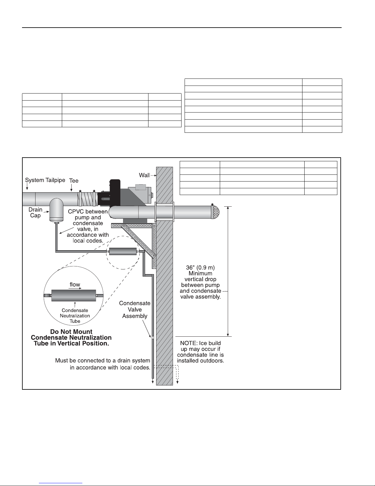
9.6.1 Condensate Neutralization Tube (optional)
If a condensate neutralization tube is specified to be
used with the heating system, follow the steps below
to choose the proper condensate neutralization tube.
See Page 20, Figure 17.
Step 1: Condensate flow (gal/h) per 100,000 Btu/h
installed
Yo u will need to know the tailpipe length per flow unit
and the total input (Btu/h) on the heating system.
Please refer to the following chart to determine the
condensate flow (gal/h) per 100,000 Btu/h installed:
Radiant Tube
Length
(average distance
between burners)
Minimum N/A 0.1 0.3 0.6
Recommended 0.1 0.3 0.6 0.8
Maximum 0.3 0.6 0.8 0.8
Minimum Recommended
Tailpipe Length per Flow Unit
1.7 ft/flow
unit
Maximum
Step 2: Total condensate
Determine the total condensate (gal/h) u
sing the
follow calculation:
Total condensate (gal/h) = Total Input (Btu/h) /
100,000 (Btu/h) x condensate flow (gal/h)
Step 3: Choose the condensate neutralization
tube
Choose the condensate neutralization tube which is
closest to and higher than the calculated gal/h value.
Calculated gal/h Description Part Number
Less than 2 Condensate Neutralization Tube 200 01327002
Less than 6 Condensate Neutralization Tube 600 01327003
Less than 10 Condensate Neutralization Tube 1000 01327004
Less than 20 Condensate Neutralization Tube 2000 01327005
Example:
®
CORAYVAC
system has a total input of 600,000
Btu/h. The radiant tube length and tailpipe are set-up
according to the RECOMMENDED specifications.
Step 1: Condensate flow (gal/h) per 100,000
Btu/h installed
Select 0.3 from the Condensate flow chart.
Radiant Tube
Length
(average distance
between burners)
Minimum N/A 0.1 0.3 0.6
Recommended 0.1 0.3 0.6 0.8
Maximum 0.3 0.6 0.8 0.8
Minimum Recommended
Tailpipe Length per Flow Unit
1.7 ft/flow
unit
Maximum
Step 2: Total condensate
Multiply the total input Btu/h / 100,000 by the
condensate flow (gal/h) per 100,000 (Btu/h)
(600,000/100,000) x 0.3 = 1.8 (gal/h)
19 of 27
Page 26
EP-200 SERIES PUMP INSTALLATION, OPERATION AND SERVICE MANUAL
Calculated gal/h Description Part Number
Less than 2 Condensate Neutralization Tu be 200 01327002
Less than 6 Condensate Neutralization Tu be 600 01327003
Less than 10 Condensate Neutralization Tu be 1000 01327004
Less than 20 Condensate Neutralization Tube 2000 01327005
Step 3: Choose the condensate neutralization
tube
Choose the condensate neutralization tube which is
closest to and higher than the calculated gal/h value.
For this example, the total condensate is 1.8 (gal/h),
the condensate neutralization tube which is closest
to and higher than the calculated gal/h value is P/N
01327002.
Calculated gal/h Description Part Number
Less than 2 Condensate Neutralization Tube 200 01327002
Less than 6 Condensate Neutralization Tube 600 01327003
Less than 10 Condensate Neutralization Tube 1000 01327004
Less than 20 Condensate Neutralization Tube 2000 01327005
FIGURE 17: Condensate Neutralization Tube
NOTE: Condensate neutralization tubes must be
replaced yearly (every 2000 operating hours) or
check condensate water pH level. If it is below pH 6,
replace tube.
To order replacement, see the chart below:
Description Part Number
Condensate Neutralization Tube 200 01327002
Condensate Neutralization Tube 600 01327003
Condensate Neutralization Tube 1000 01327004
Condensate Neutralization Tube 2000 01327005
Refill, Condensate Neutralization Tube 600 01327007
Refill, Condensate Neutralization Tube 1000 01327008
Refill, Condensate Neutralization Tube 2000 01327009
20 of 27
Page 27
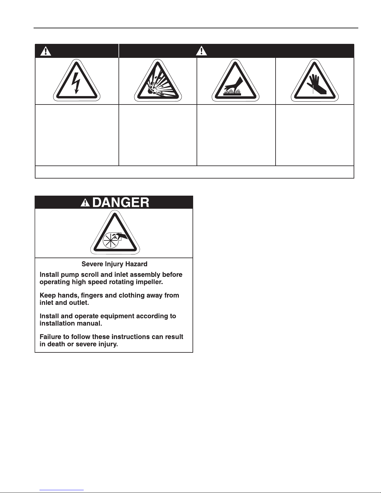
SECTION 10: SERVICING INSTRUCTIONS
Cut/Pinch Hazard
Wear protective gear
during installation,
operation and service.
Edges are sharp.
WARNING
Failure to follow these instructions can result in death, electric shock, injury or property damage.
Burn Hazard
Allow heater and
pump to cool before
service.
Tubing may still be hot
after operation.
Explosion Hazard
Turn off gas supply to
heater before service.
DANGER
Electrical Shock Hazard
Disconnect electric
before service.
Heater and pump must
be connected to a
properly grounded
electrical source.
SECTION 10: SERVICING INSTRUCTIONS
10.1 Pre-Season Maintenance and Annual
Inspection
To e n s ure your safety and years of trouble-free operation of the pump, service and annual inspections
must be done by a contractor qualified in the installation and service of gas-fired heating equipment.
Disconnect electric and gas supplies before performing service or maintenance.
Before every heating season, a contractor qualified in
the installation and service of gas-fired heating
equipment must perform a thorough safety inspection of the pump.
For safety and best performance, the electrical, vent-
ing, suspensions and overall p
some of the areas requiring inspection.
Please see Page 23, Section 10.3 for suggested
items to inspect.
Disassembly and removal or replacement of any
pump components must be done by a service contractor or electrician qualified in the installation and
service of gas-fired heating equipment.
Overtorquing can result in a failure of components.
Failure to follow these instructions can compromise
pump operation and void warranty.
10.2 To Change the Motor and/or the Impeller
1. Diconnect electrical before servicing.
2. To remove the motor or impeller, the scroll must
be opened. Remove the eight nuts/bolts and
insert a knife blade between the scroll halves to
cut through the factory applied sealant. Separate the two halves.
3. The impeller can be removed by loosening the
two 3/8-24 set screws, removing the 10-32
screw and retainer assembly. With an appropriate wheel puller, remove the impeller.
ump condition are
21 of 27
Page 28

EP-200 SERIES PUMP INSTALLATION, OPERATION AND SERVICE MANUAL
4. The motor can now be removed, if necessary,
by loosening the attachment hardware.
5. Re-assembly of motor/impeller combination
require proper alignment. Make sure the impeller has a 1/4" (6 mm) clearance off the inside
wall of the scroll. Verify proper motor alignment
and free rotation.
6. The two) impeller set screws should be removed
and reinstalled with a drop of thread locking
sealant and remain unseated during initial reassembly.
7. Slide the impeller onto the motor shaft end.
Apply a drop of thread locking sealant to the
threads of the retainer screw/washer assembly.
Insert the retainer screw into the shaft so that it
bottoms on the end of the shaft and hub of the
impeller. Torque to 30 in/lb.
8. Seat the two impeller set screws. Torque to 100
in/lbs.
9. Re-attach the scroll halves. Apply a bead of high
temperature silicone sealant (600°F) to the
scroll halves. Secure with all seven nuts/bolts.
To rq ue to 150 in/lb.
22 of 27
Page 29

10.3 Maintenance Checklist
Installation Code and Annual Inspections:
All installation and service of ROBERTS GORDON
®
equipment must be performed by a contractor
qualified in the installation and service of equipment
sold and supplied by Roberts-Gordon LLC and
conform to all requirements set forth in the
®
ROBERTS GORDON
manuals and all applicable
governmental authorities pertaining to the
installation, service, operation and labeling of the
equipment. To help facilitate optimum performance
and safety, Roberts-Gordon LLC recommends that a
qualified contractor conduct, at a minimum, annual
inspections of your ROBERTS GORDON
®
equipment and perform service where necessary,
using only replacement parts sold and supplied by
Roberts-Gordon LLC
System Tubing and Vent
Pipe
Vent ing must be intact. Using a flashlight, look for obstructions, cracks on the
pipe, gaps in the sealed areas or corrosion.
The area must be free of dirt and dust or blockage.
SECTION 10: SERVICING INSTRUCTIONS
.
Remove any carbon deposits or scale using a wire brush.
Replace pipe if there are any holes due to corrosion. Seal any gaps in venting
to prevent condensate leakage.
Pump Scroll, Impeller and
Motor
Compressed air or a vacuum cleaner may be used to clean dust and dirt.
Check for corrosion, if any parts have corroded through, replace as necessary.
Ensure all hex nuts are tight for proper seal.
Suspension Points Make sure the pump is hanging securely.
Look for signs of wear on the mounting angles, wall mounting points or ceiling
mounting points.
Pump Boot Inspect pump boot at pump inlet and outlet for cracking or deterioration.
Replace if cracks are found.
Ensure band clamps are tight at all connection points.
Condensate Trap, Drain
Cap
Check connection of tee to drain cap and between tee and condensate trap.
Seal connections between tee and drain cap to prevent condensate leakage.
Screw condensate trap tightly into drain cap or p
ump inlet assembly to pre-
vent leakage.
Condensate trap should be filled with water.
Pressure Switch Ensure that wiring is intact. Check silicone hose for cracks.
Ensure secure connection between pressure switch and barbed fitting.
Safety Labels Product safety signs or labels should be replaced by the product user when
they are no longer legible. Please contact Roberts-Gordon LLC or your ROB-
ERTS GORDON
®
independent distributor to obtain replacement signs or
labels. See Page 2, Figure 1.
23 of 27
Page 30
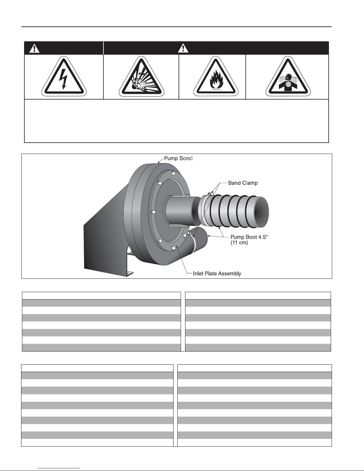
EP-200 SERIES PUMP INSTALLATION, OPERATION AND SERVICE MANUAL
Carbon Monoxide Hazard
WARNING
Use only genuine ROBERTS GORDON® replacement parts per this installation, operation and
service manual.
Failure to follow these instructions can result in death, electric shock, injury or property damage.
Explosion Hazard
DANGER
Electrical Shock Hazard
Fire Hazard
SECTION 11: REPLACEMENT PARTS AND ACCESSORIES
11.1 Replacement Parts
Description Part Number Description Part Number
EP-201 Motor 3/4 HP, 115 V, 1 Ø 90604500 Bird Screen w/ clamp 01312200
EP-203 Motor 3/4 HP 208 V - 230 V/ 460 V, 3 Ø 90604501 Shaft Seal 02757500
Impeller - 5/8" Bore 01394602 Damper Assembly 01313800
Impeller - 1/2" Bore 01394600 Mounting Angle Assembly 01312102
Pressure Switch Kit 90430600K Inlet Plate Assembly Kit 01327401
Rubber Mounts for Pump Motor 91906100 Flexible Boot Replacement Package 02771000
Pump Scroll 01394401
11.2 Accessories
Description Part Number Description Part Number
4" Plain Coupling 01312700 4" Aluminized 90° Elbow 01335801
6" Plain Coupling 01312706
4" Lined Coupling
4" Damper Coupling 01331900
6" Damper Coupling E0009356 4" Aluminized Non Heat Treated 10’ Tube 91409403
4" Aluminized Tee 01330203
6" Aluminized Tee 01330204 4" Coated 10’ Tube 9141030D
4" Coated Tee 0133022D
6" Coated Tee 0133025D 6" Tube Hanger 91240010
4" Aluminized Cross 01330903
0131270I
6" Aluminized 90° Elbow T0100320
4" Coated 90° Elbow 0133580D
6" Coated 90° Elbow 0133660D
6" Aluminized Non Heat Treated 10’ Tu be 91409420
Aluminized Tube adapter (6" dia. x 4" dia.) 91418200
6" Aluminized Cross 01330904
24 of 27
Page 31

SECTION 11: REPLACEMENT PAR TS AND ACCES SORIES
Description Part Number Description Part Number
Schedule 40 Damper Nipple 01322000 4" Drain Cap 02718851
4" Coated Cross 0133092D
6" Drain Cap 02718852
5" (13 cm) Band Clamp 91901301 Condensate Trap 01327001
6" (15 cm) Band Clamp 91913703
25 of 27
Page 32
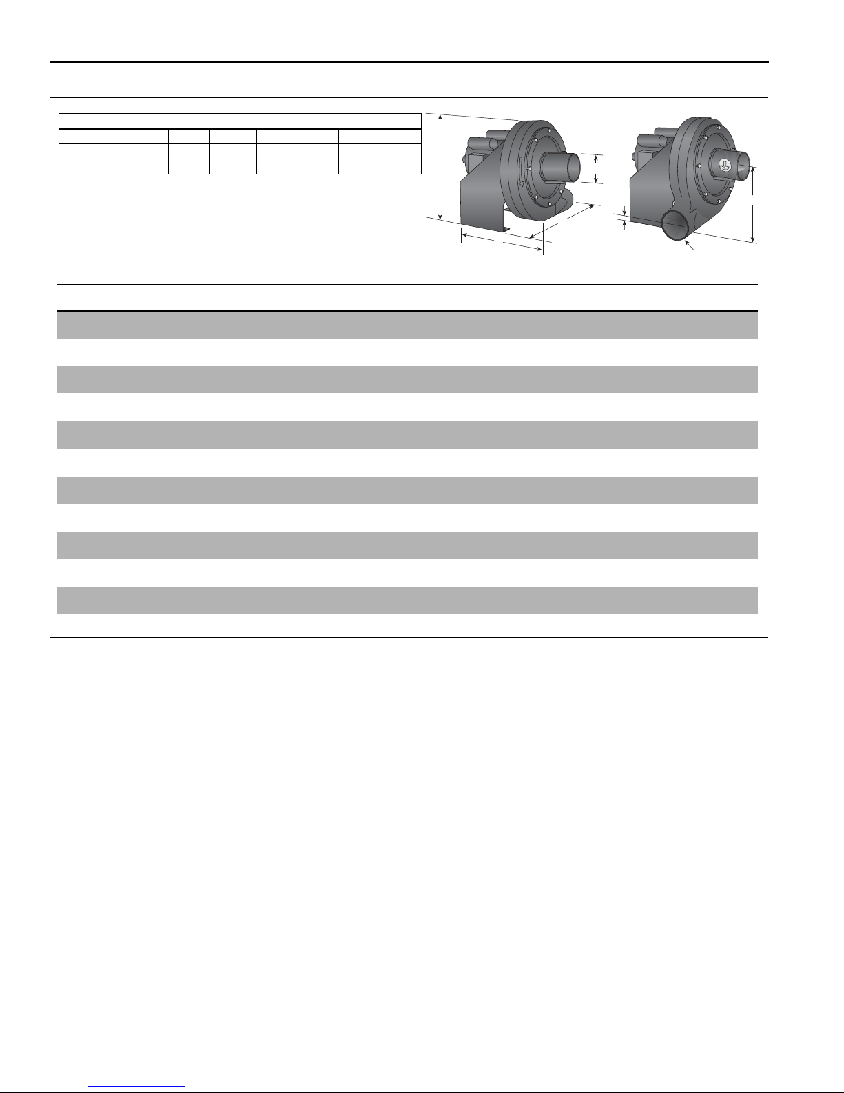
EP-200 SERIES PUMP INSTALLATION, OPERATION AND SERVICE MANUAL
C
B
G
A
E
D
F
dia.
Pump Specifications
Model EP-201 EP-203
Horsepower (Hp) 3/4 3/4
Phase (Ø)13
Hertz (Hz) 60 60
Voltage (V) 115/208 - 230 208 - 230 / 460
Full Load Amp (A) 8.0/4.42 - 4.0 2.5 - 2.26/1.13
R.P.M. 3500 3475
Motor Frame 56 56
Motor Enclosure TEFC TEFC
Noise Level @ 5' dB(A) 70 N/A
Inlet/Outlet (In.) 4.5/4.5 4.5/4.5
Weight (lbs.) 112 11 2
Pump Dimensional Data (in.)
Model ABCDEFG
EP-201
17.75 17 20.25 3.25 10 4.5 4.5
EP-203
SECTION 12: SPECIFICATIONS
12.1 Material Specifications
12.1.1 Pump, Frame, Scroll Materials
12 Gauge Stamped Steel Construction
12.1.2 Impeller Materials
319 Cast Aluminum
12.2 Suspension Specifications
Hang pump with materials with a minimum working
load of 750 lbs (340 kg).
12.3 Controls Specifications
Time switches, thermostats, etc. can be wired into
the electrical supply. External controls supplied as an
optional extra. See the heaters’ Installation, Operation and Service Manual for details.
26 of 27
Page 33

SECTION 13: THE ROBERTS GOR DON® EP-200 SERIES PUMP WARRANTY
SECTION 13: THE ROBERTS GORDON
®
EP-200
SERIES PUMP WARRANTY
ROBERTS-GORDON LLC WILL PAY FOR:
Within 36 months from date of purchase by buyer or 42
months from date of shipment by Roberts-Gordon LLC
(whichever occurs first), replacement parts will be provided
free of charge for any part of the product which fails due to
a manufacturing or material defect.
Roberts-Gordon LLC will require the part in question to be
returned to the factory. Roberts-Gordon LLC will, at its sole
discretion, repair or replace after determining the nature of
the defect and disposition of part in question.
ROBERTS GORDON
®
Replacement Parts are warranted
for a period of 12 months from date of shipment from
Roberts-Gordon LLC or the remaining
GORDON
®
EP-200 Series Pump warranty.
ROBERTS
ROBERTS-GORDON LLC WILL NOT PAY FOR:
Service trips, service calls and labor charges.
Shipment of replacement parts.
Claims where the total price of the goods have not
been paid.
Damage due to:
• Improper installation, operation or maintenance.
• Misuse, abuse, neglect, or modification of the
ROBERTS GORDON
®
EP-200 Series Pump in any
way.
®
• Use of the ROBERTS GORDON
EP-200 Series
Pump for other than its intended purpose.
• Incorrect gas or electrical supply, accident, fire,
floods, acts of God, war, terrorism, or other casualty.
• Improper service, use of replacement parts or
accessories not specified by Roberts-Gordon LLC.
• Failure to install or maintain the
ROBERTS GORDON
®
EP-200 Series Pump as
directed in the Installation, Operation and Service
Manual.
®
• Relocation of the ROBERTS GORDON
EP-200
Series Pump after initial installation
®
• Use of the ROBERTS GORDON
EP-200 Series
Pump in a corrosive atmosphere containing
contaminants.
®
• Use of the ROBERTS GORDON
EP-200 Series
Pump in the vicinity of a combustible or explosive
material.
®
• Any defect in the ROBERTS GORDON
EP-200
Series Pump arising from a drawing, design, or
specification supplied by or on behalf of the
consumer.
• Damage incurred during shipment. Claim must be
filed with carrier.
WARRANTY IS VOID IF:
The ROBERTS GORDON
installed by an contractor qualified in the installation and
service of gas fired heating equipment.
Yo u cannot prove original purchase date and required
annual maintenance history.
®
EP-200 Series Pump is not
The data plate and/or serial number are removed,
defaced, modified or altered in any way.
The ownership of the
ROBERTS GORDON
®
EP-200
Series Pump is moved or transferred. This warranty is
non-transferable.
Roberts-Gordon LLC is not permitted to inspect the
damaged equipment and/or component parts.
READ YOUR INSTALLATION, OPERATION AND
SERVICE MANUAL.
If you have questions about your equipment, contact your
installing professional. Should you need Replacement
Parts or have additional questions, call or write:
Roberts-Gordon LLC
1250 William Street
P. O . B o x 4 4
Buffalo, New York 14240-0044
Telephone: +1.716.852.4400
Fax: +1.716.852.0854
Toll Free: 800.828.7450
www.robertsgordon.com
Roberts-Gordon LLC's liability, and your exclusive
remedy, under this warranty or any implied warranty
(including the implied warranties of merchantability
and fitness for a particular purpose) is limited to
providing replacement parts during the term of this
warranty. Some jurisdictions do not allow limitations on
how long an implied warranty lasts, so this limitation may
not apply to you. There are no rights, warranties or
conditions, expressed or implied, statutory or otherwise,
other than those contained in this warranty.
Roberts-Gordon LLC shall in no event be responsible
for incidental or consequential damages or incur
liability for damages in excess of the amount paid by
you for the
ROBERTS GORDON
®
EP-200 Series
Pump. Some jurisdictions do not allow the exclusion or
limitation of incidental or consequential damages, so this
limitation or exclusion may not apply to you. This warranty
gives you specific legal rights, and you may also have
other rights which vary from jurisdiction to jurisdiction.
Roberts-Gordon LLC shall not be responsible for failure to
perform under the terms of this warranty if caused by
circumstances out of its control, including but not limited to
war, fire, flood, strike, government or court orders, acts of
God, terrorism, unavailability of supplies, parts or power.
No person is authorized to assume for Roberts-Gordon
LLC any other warranty, obligation or liability.
LIMITATIONS ON AUTHORITY OF
REPRESENTATIVES:
No representative of Roberts-Gordon LLC, other than an
Executive Officer, has authority to change or extend these
provisions. Changes or extensions shall be binding only if
confirmed in writing by Roberts-Gordon LLC's duly
authorized Executive Officer.
27 of 27
Page 34

EP-200 SERIES PUMP INSTALLATION, OPERATION AND SERVICE MANUAL
28 of 27
 Loading...