

Roberts 10-91, 10-94, 10-99 Owner's Manual
Multi-Floor Cutters
OWNER’S MANUAL
Coupeuse à planchers multiples
MANUEL D’UTILISATION
Cortador para múltiples pisos
MANUAL DE OPERACIÓN
WARNING Read and understand all instructions. Failure to follow all instructions may result in serious
bodily injury. SAVE THESE INSTRUCTIONS FOR FUTURE REFERENCE.
AVERTISSEMENT Lire et comprendre toutes les directives. Le non-respect des directives peut causer des
blessures graves.VEUILLEZ CONSERVER CES DIRECTIVES POUR RÉFÉRENCE ULTÉRIEURE.
ADVERTENCIA Lea y comprenda todas las instrucciones. Si no se cumplen todas las instrucciones a puede
producir lesiones físicas graves. CONSERVE ESTAS INSTRUCCIONES PARA CONSULTARLAS EN EL FUTURO.
10-91
10-94
10-99

- 1 -
SAFETY RULES FOR THE MULTI-FLOOR CUTTER
WARNING! FAILURE TO FOLLOW THESE RULES MAY RESULT IN SERIOUS
INJURY! USING THIS MACHINE WITH RESPECT AND CAUTION WILL
CONSIDERABLY LESSEN THE POSSIBILITY OF PERSONAL INJURY.
1. READ AND UNDERSTAND THIS INSTRUCTION MANUAL BEFORE OPERATING
THE MULTI-FLOOR CUTTER.
2. If you are not thoroughly familiar with the operation of the Multi-Floor Cutter,
obtain advice from a qualified instructor or call 866-435-8665
3. Stay alert. Do not operate while under the influence of drugs, alcohol,
or medication.
4. Always wear safety approved eye protection with side shields (ANSI Z87.1)
5. Keep work area and free of debris.
6. Keep children and unauthorized persons away from the Multi-Floor Cutter and
work area.
7. Make sure tool is secure. Operate only on a firm substrate or solid stand.
8. Use the right tool. Do not force the Multi-Floor Cutter or use it for a job for
which it was not designed; use only on approved materials.
9. Keep blade sharp. A dull blade will not perform properly.
10. Always keep hands away from blade while operating or carrying.
11. Do not alter or misuse this tool. The Multi-Floor Cutter is precision built;
modifications not specified in this manual may result in a dangerous condition.
12. Maintain the Multi-Floor Cutter with care. Keep blade sharp and clean. Follow
instructions for lubricating and changing accessories.
13. Use only recommended accessories. The use of improper accessories may
cause hazards or injury.
14. Never leave the Multi-Floor Cutter unattended. Secure the handle with the lock
chain when not in use.
15. Warning: The dust generated by cutting certain wood, wood fiber and / or PVC
products can be harmful to your health.
- 2 -
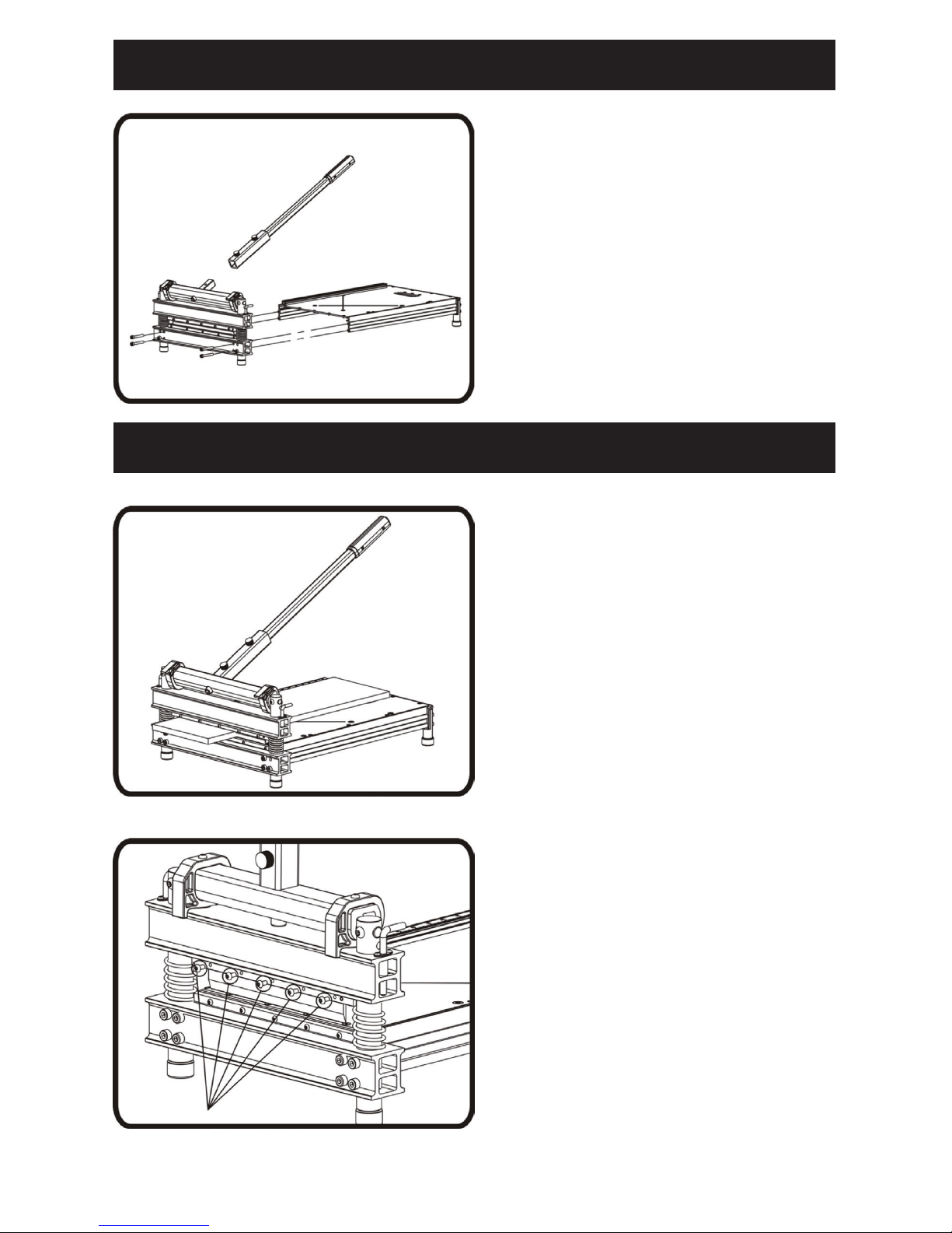
SET UP OF THE CUTTER
Install the table to the cutter base with
provided screws and bolts
as shown.
Pull up the lock pin on the aluminum
handle as shown and insert the handle
into the handle base as shown.
Warning: Do not put your fingers against
the sharp edge of the blade at any time.
CUTTING PREPARATION
Adjust the angle attachment to desired
angle as needed.
The angle attachment can be used on
left side of the table as shown.
Warning: Do not put your fingers against
the sharp edge of the blade at any time.
STRAIGHT CUTTING
Insert material between the cutting
blade and the base, flush it with the
guide bar as shown and hold the
material then push handle down to
complete a cut.
Warning: Maintain control of the handle.
Do not allow handle to slam back after
making a cut.
45° CUTTING
Adjust the angle attachment to 45°.
Insert material between the cutting
blade and the base, against the angle
attachment as shown, then push the
handle down to complete a cut.
Warning: Maintain control of the handle.
Do not allow handle to slam back after
making a cut.
Warning: Do not put your fingers against
the sharp edge of the blade at any time.
SET UP
CUTTING
- 3 -
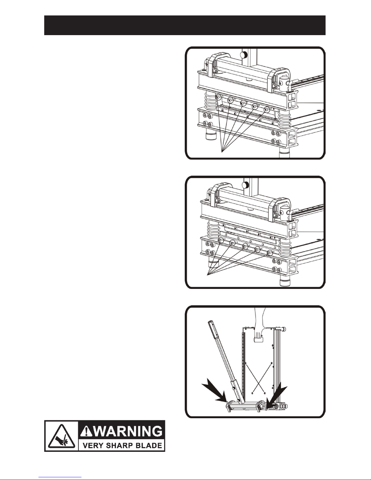
MAINTENANCE
CHANGING THE BLADE
Use Roberts #10-910 (9"), 10-940 (13”)
or 10-990 (18”) Replacement Blade. Use
the provided Allen wrench to remove
the screws, then hold the blade at each
end and carefully move the blade out of
blade holder.
Note: The flat side of the blade should
face the table.
Warning: Do not put your fingers against
the sharp edge of the blade at any time.
CHANGING THE NYLON BAR
Use the provided Allan wrench to
remove the screws, then hold the nylon
bar and carefully move it out of nylon
bar holder.
Warning: Do not put your fingers against
the sharp edge of the blade at any time.
TRANSPORT
Insert the pin as shown to the hole in the
aluminum eccentric cam and carry the
cutter as shown.
- 4 -
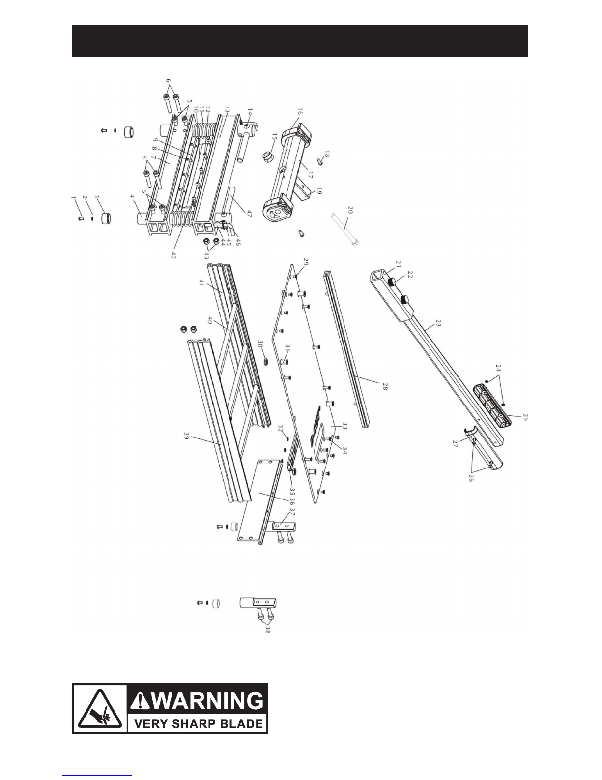
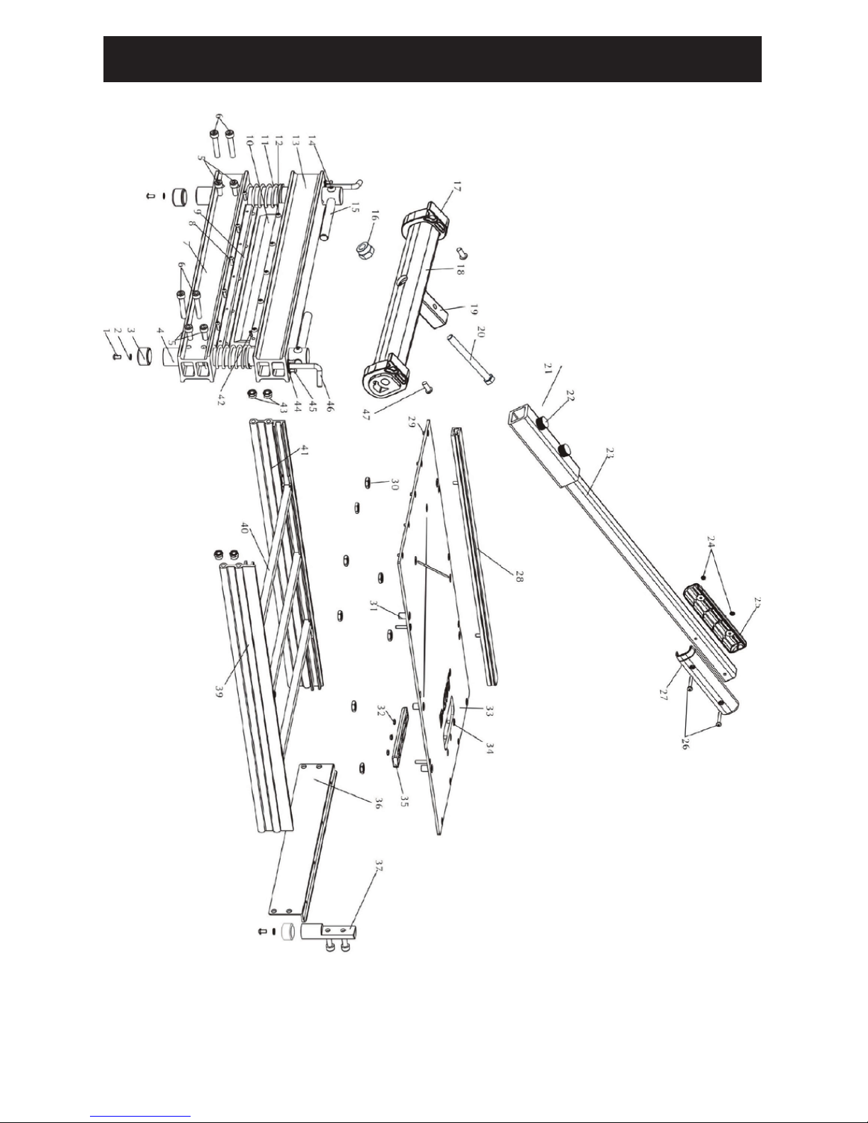
ROBERTS 10-91 EXPLODED PARTS DIAGRAM

- 5 -
ROBERTS 10-91 PARTS LIST
NO. DESCRIPTION QTY. NO. DESCRIPTION QTY.
1 Screw M6 × 12 4 25 Right ABS Handle 1
2 Washer Φ6 2 26 Bolt M4 × 30 2
3 Rubber Feet 6 27 Left ABS Handle 2
4 Rod 4 28 Guide Bar 1
5 Hex Bolt M8 × 55 1 29 Screw M5 × 8 8
6 Hex Bolt M8 × 50 1 30 Nut M10 4
7 Main Base 2 31 Sleeve 6
8 Screw M4 × 14 2 32 Nut M5 3
9 Nylon Bar 2 33 Working Table 3
10 Blade 2 34 Screw M5 ×12 3
11 Spring 2 35 Carry Handle 3
12 Screw M5 × 10 1 36 End Board 1
13 Blade Base 2 37 Foot 1
14 Screw M8 × 14 1 38 Bolt M8 × 30 4
15 Nut M12 1 39 Frame A 1
16 Nylon Wheel 2 40 Cross Bar 3
17 Aluminum Eccentric Cam 1 41 Frame B 1
18 Screw M6 × 16 1 42 Spring Pin 1
19 Handle Base 1 43 Nut M8 4
20 Bolt M12 × 120 2 44 Pin Sleeve 2
21 Handle A 1 45 Screw M4 × 10 4
22 Screw M8 2 46 Pin 2
23 Handle B 1 47 Shaft 2
24 Nut M4 1
- 6 -
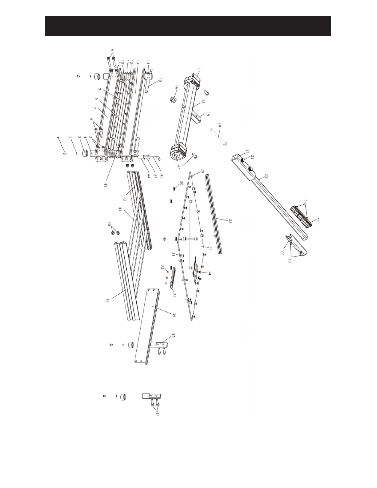
ROBERTS 10-94 EXPLODED PARTS DIAGRAM
- 7 -
ROBERTS 10-94 PARTS LIST
NO. DESCRIPTION QTY. NO. DESCRIPTION QTY.
1 Screw M6 × 12 4 25 Right ABS Handle 1
2 Washer Φ6 4 26 Bolt M4 × 30 2
3 Rubber Feet 4 27 Left ABS Handle 2
4 Rod 2 28 Guide Bar 1
5 Hex Bolt M8 × 55 4 29 Screw M5 × 8 9
6 Hex Bolt M8 × 50 4 30 Nut M10 4
7 Main Base 1 31 Sleeve 6
8 Screw M4 × 14 5 32 Nut M5 3
9 Nylon Bar 1 33 Working Table 3
10 Blade 1 34 Screw M5 ×12 3
11 Spring 1 35 Carry Handle 3
12 Screw M5 × 10 5 36 End Board 1
13 Blade Base 1 37 Foot 1
14 Screw M8 × 14 2 38 Bolt M8 × 30 4
15 Shaft 2 39 Frame A 1
16 Nut M12 1 40 Cross Bar 3
17 Nylon Wheel 2 41 Frame B 1
18 Aluminum Eccentric Cam 1 42 Sping Pin 1
19 Handle Base 1 43 Nut M8 4
20 Bolt M12 × 120 1 44 Pin Sleeve 2
21 Handle A 1 45 Screw M4 × 10 4
22 Screw M8 2 46 Pin 2
23 Handle B 1 47 Screw M6 × 16 4
24 Nut M4 2
- 8 -
ROBERTS 10-99 EXPLODED PARTS DIAGRAM

- 9 -
ROBERTS 10-99 PARTS LIST
NO. DESCRIPTION QTY. NO. DESCRIPTION QTY.
1 Screw M6 × 12 4 25 Right ABS Handle 1
2 Washer Φ6 4 26 Bolt M4 × 30 2
3 Rubber Feet 4 27 Left ABS Handle 1
4 Rod 2 28 Guide Bar 1
5 Hex Bolt M8 × 55 4 29 Screw M5 × 8 13
6 Hex Bolt M8 × 50 4 30 Nut M10 8
7 Main Base 1 31 Sleeve 8
8 Screw M4 × 14 7 32 Nut M5 3
9 Nylon Bar 1 33 Working Table 1
10 Blade 1 34 Screw M5 ×12 3
11 Spring 1 35 Carry Handle 1
12 Screw M5 × 10 7 36 End Board 1
13 Blade Base 1 37 Foot 2
14 Screw M8 × 14 2 38 Bolt M8 × 30 4
15 Shaft 2 39 Frame A 1
16 Nut M12 1 40 Nut M8 4
17 Nylon Wheel 4 41 Cross Bar 3
18 Aluminum Eccentric Cam 1 42 Spring Pin 1
19 Handle Base 1 43 Frame B 1
20 Bolt M12 × 120 1 44 Pin Sleeve 2
21 Handle A 1 45 Screw M4 × 10 4
22 Screw M8 2 46 Pin 2
23 Handle B 1 47 Screw M6 × 16 4
24 Nut M4 2
- 10 -
CUTTING CAPACITY CHART
WOOD FLOORING
JANKA HARDNESS
RATING
WILL CUT UP TO
5/8" ENGINEERED
WOOD FLOORING
Eastern White Pine 380 Yes
Basswood 410 Yes
White Pine 420 Yes
Hemlock 500 Yes
Chestnut 540 Yes
Larch 590 Yes
Douglas Fir 660 Yes
Southern Yellow Pine (Loblolly and Shortleaf) 690 Yes
Shedua 710 Yes
Sycamore 770 Ye s
Parana 780 Yes
Lacewood / Leopardwood 840 Yes
Southern Yellow Pine (Longleaf) 870 Yes
Cedar 900 Yes
Paper Birch 910 Yes
Boire 940 Ye s
Black Cherry / Imbuia 950 Yes
Sakura 995 Yes
Teak 1000 Yes
Black Walnut 1010 Yes
Boreal 1023 Yes
Makore 1100 Yes
Brazilian Eucalyptus / Rose Gum 1125 Yes
Cocobolo 1136 Yes
Carbonized Bamboo (represents one species) 1180 Yes
Heart Pine 1225 No
Movingui 1230 No
Yellow Birch 1260 No
Carribean Heart Pine 1280 No
Red Oak (Northern) 1290 No
American Beech 1300 No
Ash (White) 1320 No
Ribbon Gum 1349 No
Tasmanian Oak 1350 No
White Oak 1360 No
Australian Cypress 1375 No
Natural Bamboo (represents one species) 1380 No
Coffee Bean 1390 No
Hard Maple / Sugar Maple 1450 No
Sweet Birch 1470 No
Curupixa 1490 No
 Loading...