

Roberts 10-475 Owner's Manual
1HP Electric Floor Stripper
OWNER’S MANUAL
Arracheur de Sol Électrique de 1 CV
MANUEL D’UTILISATION
Removedor Eléctrico de 1 CF para Pisos
MANUAL DE OPERACIÓN
WARNING!
Read and understand all
instructions. Failure to follow
all instructions listed below
may result in electric shock,
fire and/or serious bodily injury.
SAVE THESE INSTRUCTIONS
FOR FUTURE REFERENCE.
A
VER
TISSEMENT!
Lire et comprendre toutes les
ectives. Le non-r
dir
ectives décrites ci-dessous
dir
peut causer des chocs
électriques, un incendie ou des
blessur
CONSER
POUR RÉFÉRENCE UL
¡ADVER
comprenda todas las
instrucciones. Si no se cumplen
todas las instrucciones
enumeradas a continuación se
puede producir choque
eléctrico, incendio y/o lesiones
físicas graves. CONSERVE
ESTAS INSTRUCCIONES PARA
CONSULTARLAS EN EL FUTURO
es graves. VEUILLEZ
VER CES DIRECTIVES
TENCIA!
espect des
TÉRIEURE.
Lea y
Patented Adjustable Blade Orbit
Lame Réglable Br
Sistema Patentado de Ajuste de la Cuchilla
con Movimiento Orbital
US PATENT 7,152,930
evetée Mouvement Orbitaire
10-475

Introduction
Your Roberts 10-475 Professional Floor Stripper machine was
designed for fast efficient removal of VCT, sheetgoods, carpet
quares, and for removal of dried adhesive from all substrates.
s
It features a patented adjustment system, which provides a
range of blade motions from a side-to-side “slicing” motion,
o a back and forth “ chopping” motion. The operator can
t
select the best blade motion pattern for a variety of jobs.
This operator’s manual contains information on machine
operation, safety, care and maintenance. Please read the
anual thoroughly before you begin operating your Stripper.
m
Contact your Robert’s distributor for spare parts, blades
nd repair.
a
ead this owner's manual completely and make sure you
R
nderstand all of it's safety guidelines.
u
General Safety Instructions
1. KEEP GUARDS IN PLACE and in working order.
REMOVE ADJUSTING KEYS AND WRENCHES. Before
2.
turning on the stripping machine, make sure the keys
and adjusting wrenches have been removed.
KEEP WORK AREA CLEAN. Cluttered areas invite
3.
accidents.
4.
ALWAYS REMAIN ALERT WHEN STRIPPER IS IN USE.
Inattention on the part of the operator may lead to
serious injury.
5.
DON’T USE IN A DANGEROUS ENVIRONMENT. Don’t
use power tools in damp or wet locations or expose
them to rain. Keep work area well lit.
KEEP CHILDREN AWAY. All visitors should remain at a
6.
safe distance from work area.
MAKE WORKSHOP CHILD-PROOF. Unplug power tools
7.
and secure dangerous tools when not in use. Lock tool
cabinets and workshop doors when unattended.
USE THE RIGHT TOOL. Don’t force a tool or attachment
8.
to do a job for which it was not designed. It has been
designed to operate at maximum safety and
performance levels.
9.
USE THE PROPER EXTENSION CORD. Make sure your
extension cord is in good condition. When using an
extension cord, be sure to use one heavy enough to
carry the current your product will draw. An undersized
cord will cause a drop in line voltage resulting in loss of
power and overheating.
use depending on cord length and nameplate ampere
rating. If in doubt, use the next heavier gauge. The
smaller the gauge number, the heavier the cord.
WEAR PROPER APPAREL. Do not wear loose clothing,
10.
neckties, rings, bracelets or other jewelry which may get
caught in moving par
recommended. Wear protective hair covering if you have
long hair. Do not wear sandals or open-toe shoes.
11.
ALWAYS USE SAFETY GLASSES AND EAR PROTECTION.
Everyday eyeglasses only have impact-resistant lenses,
they ar
for commercial stripping operations.
DON’T OVERREACH. Keep proper footing and balance at
12.
all times.
13.
MAINTAIN TOOLS WITH CARE. Keep tools clean and in
good working condition for maximum safety
per
changing accessories.
14.
DISCONNECT TOOLS BEFORE SERVICING – when
changing accessories, such as blades, bits, cutters, etc.
e NOT safety glasses. Also use face or dust mask
mance. Follow instr
for
Table 1 shows the correct size to
ts. Non-slip foot wear is
uctions for lubricating and
15. REDUCE THE RISK OF UNINTENTIONAL STARTING. Make
sure switch is in OFF position before plugging in.
6.
SE RECOMMENDED ACCESSORIES.Consult the owner’s
1
U
manual for recommended accessories. The use of improper
accessories may increase risk of injury.
7.
AKE SURE YOU USE THE CORRECT BLADEfor the
1
M
material you are cutting.
18.
NEVER STAND ON TOOL. Serious injury could occur if the
tripper is tipped or if the cutting tool is unintentionally
s
ontacted.
c
19.
CHECK DAMAGED PARTS. Before further use of the tool,
damaged part(s), (i.e., guard) should be carefully checked to
determine that it will operate properly and perform its
ntended function. Check for alignment of moving parts,
i
binding of moving parts, breakage of parts, mounting and
any other condition that may affect the stripper’s operation.
A guard or other part that is damaged should be properly
repaired or replaced.
20.
DO NOT ALTER THE PLUG OR USE SA 2-PRONG
RECEPTACLE.
electrical plug.
NEVER LEAVE TOOL RUNNING UNATTENDED. Turn power
21.
off. Don’t leave tool until it comes to a complete stop.
This stripper is equipped with a 3-prong
Electrical Requirements
•
THIS STRIPPER MUST BE CONNECTED TO A GROUNDED
POWER SOURCE while in use to protect the operator from
electrical shock.
• IN THE EVENT OF A MALFUNCTION OR BREAKDOWN,
grounding provides a path of least resistance for electrical
current to reduce the risk of electrical shock. The stripper is
equipped with an electrical cord with a grounding conductor
and a grounding plug. Insert the 3-prong electrical plug into a
3-pole receptacle that is properly installed and grounded in
accordance with all local codes and ordinances.
• DO NOT MODIFY THE PLUG provided if it will not fit the outlet.
Have the proper outlet installed by a qualified electrician.
• IMPROPER CONNECTION OF THE EQUIPMENT-GROUNDING
CONDUCTOR CAN RESULT IN A RISK OF ELECTRIC SHOCK.
The conductor with insulation that is green on the outside
(with or without yellow stripes) is the equipment-grounding
conductor. If repair or replacement of the electrical cord or
plug is necessary, do not connect the equipment-grounding
conductor to a live terminal.
•
CHECK WITH A QUALIFIED ELECTRICIAN or service personnel
if the grounding instructions are not completely understood,
or if in doubt as to whether the tool is properly grounded.
• USE ONLY 3-WIRE EXTENSION CORDS that have 3-prong
grounding plugs and 3-pole receptacles that accept the
stripper’s plug.
• REPAIR OR REPLACE DAMAGED OR WORN CORDS
IMMEDIATELY.
• IF THE PLUG OR RECEPTACLE DOES GET WET, DO NOT
UNPLUG THE CORD. Disconnect the fuse or circuit breaker
that supplies power to the tool. Then, unplug and examine for
presence of water in the receptacle.
•
ONLY UL-LISTED EXTENSION CORDS SHOULD BE USED
WITH THIS PRODUCT.
• DO NOT LET YOUR FINGERS TOUCH THE TERMINALS of plug
when installing or r
•
IMPROPER USE OF EXTENSION CORDS MAY CAUSE
INEFFICIENT OPERATION OF YOUR TOOL, which can result in
overheating. Be sure your extension cord is rated to allow
sufficient current flow to the motor. For the proper gauge for
this stripper, please refer to TABLE 1.
•
THIS MACHINE MUST BE PROPERLY GROUNDED.
The risk of electric shock and bodily injury are greatly
increased if it is not, particularly when used in damp locations
or in proximity to plumbing.
emoving the plug to or fr
om the outlet.
Extension Cords
1. Use only extension cords that are intended for outdoor use.
These extension cords are identified by a marking
“Acceptable for use with outdoor appliances: store indoors
while not in use.” Use only extension cords having an
electrical rating not less than the rating of the product. Do
not use damaged extension cords. Examine extension cord
before using and replace if damaged. Do not abuse
extension cords and do not yank on any cord to disconnect.
eep cord away from heat and sharp edges. Always
K
disconnect the extension cord from the receptacle before
disconnecting the product from the extension cord.
2.
WARNING - To reduce the risk of electrocution, keep all
onnections dry and off the gound. Do not touch plug with
c
et hands.
w
3. Gound Fault circuit Interrupter (GFCI) protection should be
rovided on the circuit(s) or outlet(s) to be used for the
p
stripper. Receptacles are available having built-in GFCI
protection and may be used for this measure of safety.
4.
Use proper extension cord. Make sure your extension cord
is in good condition. When using an extension cord, be
sure to use a cord heavy enough to carry the current your
product will draw. An undersized cord will cause a drop in
line voltage, resulting in loss power and overheating.
TABLE 1 below shows the correct size to use depending on
cord length and nameplate ampere rating. If in doubt, use
the next heavier gauge.
The smaller the gauge number, the heavier the cord.
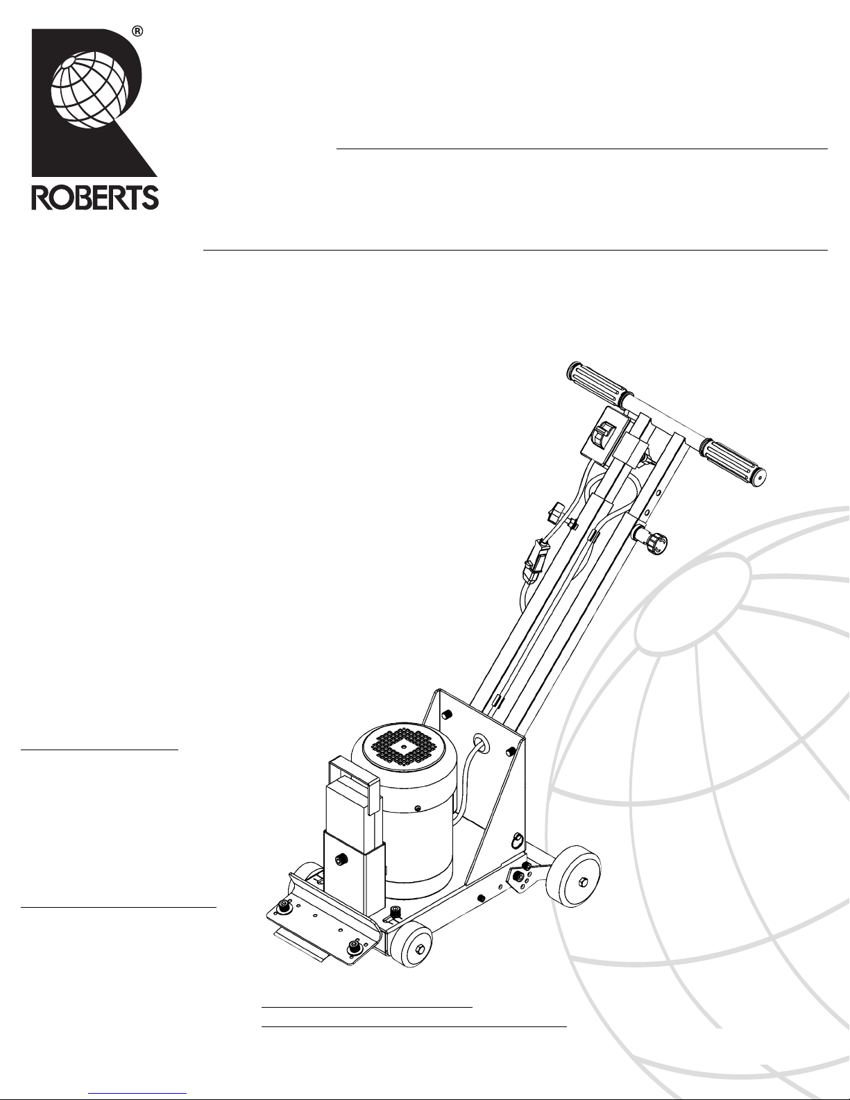
NOTE: This tool is intended for use on a circuit that has an
outlet that looks like the one illustrated in Fig. 1 (B). The
tool has a grounding plug that looks like the plug illustrated
in Fig. 1 (A). The green-colored rigid prongs extending
from the adapter must be connected to a permanent
ground such as a properly grounded outlet box.
FIGURE 1
METAL
(A) GROUNDING PIN
(B) GROUNDED
OUTLET BOX
SCREW
Tool Specific Safety Instructions
1. WEAR SAFETY EYE GLASSES, ear protection, work gloves
and safety shoes while operating the floor stripper.
EAR
W
2.
DISCONNECT THE ELECTRIC POWER CORD before changing
stripper blades or making adjustments to the stripper.
3.
DO NOT USE THE STRIPPER IN STANDING WATER OR
PUDDLES.
4.
FOLLOW ALL RECOMMENDATIONS FOR ELECTRICAL
CONNECTIONS
.
5
A
6.
DO NOT LEAVE STRIPPER UNATTENDED unless the machine
is turned off and the power cord disconnected.
andals, soft shoes or open-toe shoes
s
Electric shock can occur.
and use of extension cords.
VOID HITTING NAILSand other metal objects.
DO NOT
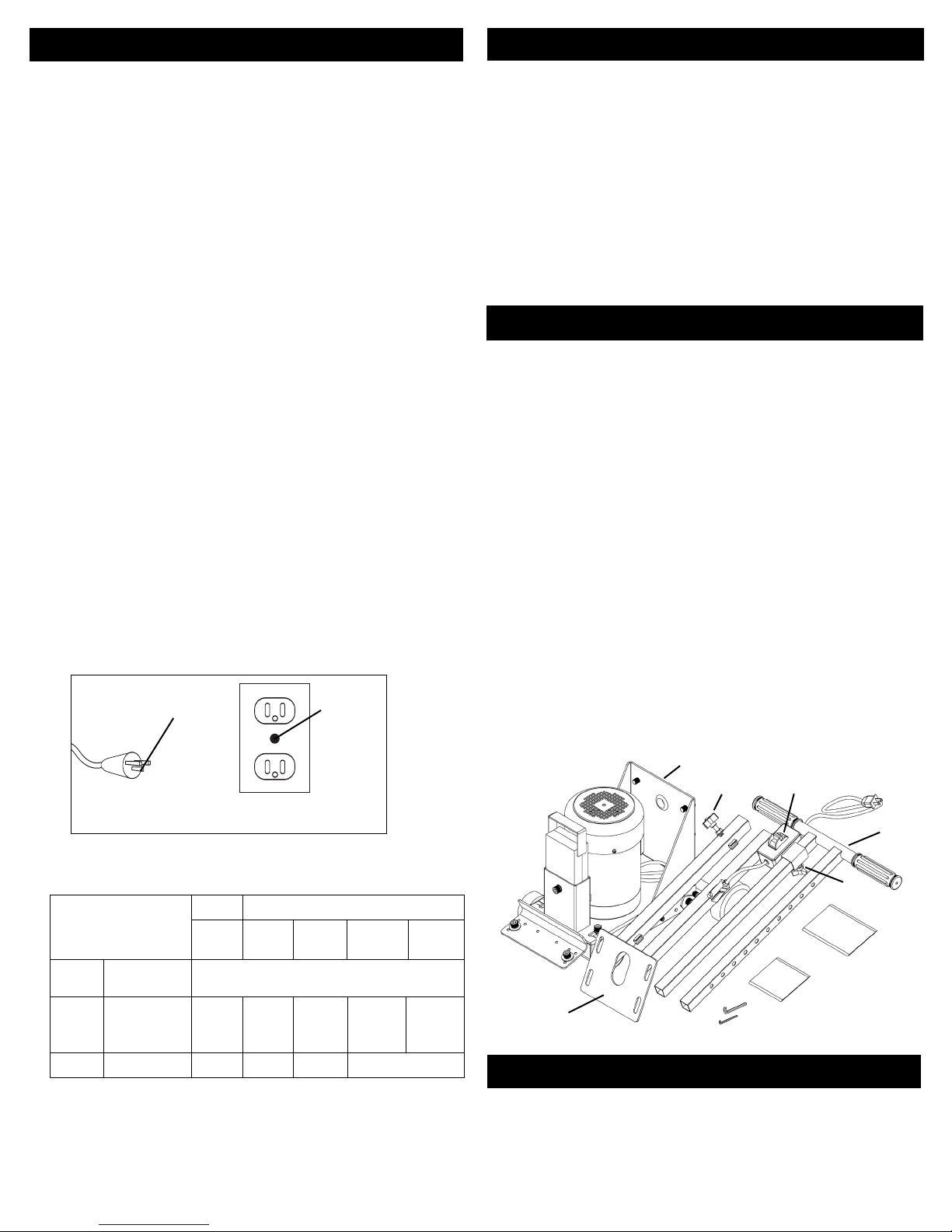
Assembly of the Stripper
1. Remove all parts from the box. Allen hex wrenches are included
for all socket cap bolts used on the stripper machine.
2. Set the motor/blade holder unit (a) upright on solid surface.
Attach the red lower Handle Unit (B) to the upright plate at the
rear of the Motor Unit (A) with four socket cap bolts, lock
washers, and nuts supplied. Tighten the bolts securely with the
ench. For future reference, not that this lower handle can
hex wr
be adjusted up or down to suit the operator’s preference.
3. Lay the upper (silver) handle assembly (c) down, so the leg with
the holes drilled through is to the left, as it appears in the
drawing. Slide the switch box (D) on to the right leg with the
rocker switch facing up, or it can be mounted on the left leg if
you prefer the switch to be in the center.
4. Slide the upper (silver handle assembly (C) into the lower (red)
handle tubes (B).
5. Tighten the switch locking screw (E). Plug the electric cord
from the switch into the motor cord. Set the handle height at
a desired level, and secure it with the pin on the left leg, and
tighten the screw (F) on the right side. Note the pin on the left
side secures the handle at 1-1/2'' increments up and down.
A clip on the right handle leg secures the power cord.
6. For transportation, the handle may be removed easily.
Remove the pin, loosen the right hand screw (F) and unplug
the electric cord.
(A)
(F)
(D)
(C)
TABLE 1
Total length of cord in feet
olts
V
Amper
e Rating
More Not More
Than Than
06
6
10
10 12
12
NOTE: When using an extension cord, ensure all cords are no
smaller than #12 gauge, rated at a 20-amp minimum, and
equipped with 3-prong plugs. Using anything smaller may
result in overheating, loss of power or burn out of the motor.
16
120V 25ft. 50ft. 100ft. 150ft.
240V 50ft. 100ft. 200ft. 300ft.
WG
A
18 16 16 14
18 16 14 12
16 16 14 12
14 12
Not
Recommended
(E)
(B)
Handle Adjustment
The handle adjusts up and down to provide comfortable
settings. On the left Handle Tube, there is a Locking Pin which
engages holes in the inside (silver) handle tube. The Holes are
spaced at 1-1/2'' increments. It is recommended that the screw
lock on the right handle tube be tightened after the desir
height is selected. This will provide maximum security of the
Handle assembly.
ed
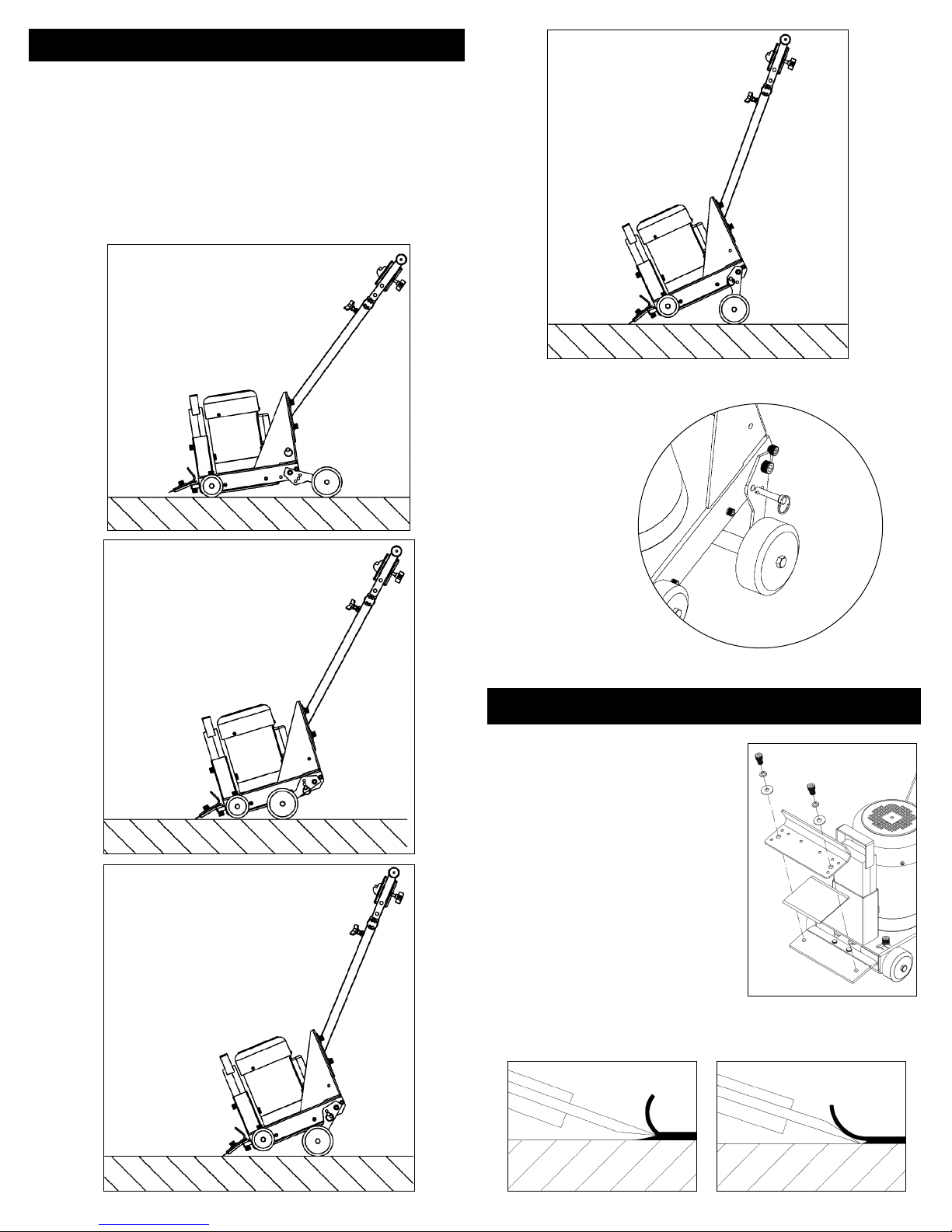
Wheel Adjustment
The rear wheels can be set in three positions to provide the
optimal blade contact angle with the floor. The two Rear
Wheel Adjustment Plates can be adjusted by removing the
two Security Pins, setting the wheel at the desired height,
then reinserting the two pins through holes in the Adjustment
plates and the Frame of the Stripper.
For transport, flip the wheel assembly to the rear of the
Stripper Machine.
The positions are shown in the illustrations below.
TRANSPORT
HIGHEST
POSITION
SECURITY PIN
For Wheel Height
Adjustment
LOW ANGLE
POSITION
MIDDLE
POSITION
Installing and Changing Blades
Blades are held in place between
the Upper and Lower Blade
Holder plates by two Hex Cap
Bolts. The Lower Blade Holder
Plate is thr
required. To change blades,
loosen the two hex cap bolts;
remove the blade, and install a
new blade. Note the Robert’s
blades are sharpened on both
sides, so the blade can be
reversed to get a sharp edge.
eaded, so nuts are not
BEVEL DOWN FOR
WOOD SURFACE
BEVEL UP FOR
CONCRETE SURFACE
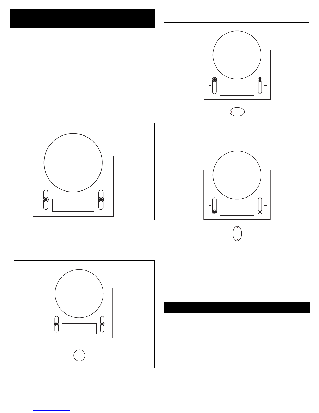
Patented Adjusting Blade
Orbit Motion
he Roberts Floor Stripper can be adjusted to produce different
T
blade motions, from a “slicing” side-to-side orbit, to a
“Chopping” back and forth motion.
he motion is set by sliding the Pivot of the Driver Bar forward
T
r backward.
o
WARNING: DISCONNECT THE ELECTRIC POWER TO YOUR
STRIPPER BEFORE ADJUSTING THE PIVOT!
Two large Hex Cap bolts are located toward the front of the
Stripper base, one on each side, as shown in Figure A. To
adjust the Pivot, loosen both bolts by turning counter-clockwise
with the Allen wrench supplied. Slide the pivot to the desired
blade motion.
If the Pivot is moved to the full back position (Figure A-2), the
blade will move in a side-to-side, or “slicing” motion.
FIGURE
A-2
Motor
Pivot in
BACK
osition
eight Box
W
Blade Orbit
with Pivot in
BACK Position
P
FIGURE A
Motor
Pivot
Adjustment
Weight Box
In the center, the blade motion will be circular in shape, as
most strippers operate. This is shown in Figure A-1.
Bolt
FIGURE
A-1
Motor
By setting the Pivot full forward, as shown in Figure A-3, the
blade will move in a back and forth “chopping” path.
FIGURE
A-3
Motor
Pivot in
FRONT
Weight Box
Blade Orbit
with Pivot in
FRONT Position
The Pivot may be set in any position, to produce the best blade
action for your job. By experimenting with different settings,
you can determine the blade motion you prefer.
Note the blade motion patterns in these illustrations is
exaggerated to show the dif
settings.
CAUTION: TIGHTEN THE TWO HEX CAP BOLTS TIGHTLY
BEFORE CONNECTING THE ELECTRIC POWER AND USING
YOUR STRIPPER!
ferent r
esults for dif
Position
ferent pivot
Care and Maintenance
Weight Box
Blade Orbit Pattern,
with Pivot in
CENTER Position
Pivot
CENTERED
1. As with any major power tool, keep your Roberts Stripper
clean, and do not leave the machine outside in the weather.
2. Inspect the Stripper regularly. If the blade is chipped, cracked, or
dull, replace it. Roberts’s blades are sharpened on two edges, so
the blade can be reversed and used. Check the electrical cord. If
there are cracks or cuts, immediately replace the cord.
3. Occasionally – every couple of months – turn the Stripper upside
down and remove the bottom cover plate, by removing the four
small Cap scr
foreign material. Apply light grease in the slot where the Pivot
slides back and for
4. Some users wrap Duct tape around the rubber wheels so
adhesive can be removed easily.
5. Make sure all bolts and fasteners are tightened. Due to the
mal vibration of Floor Strippers. Fasteners can come loose.
nor
ews. Check for dir
th. Bearings ar
t and debris, and r
e self-lubricating.
emove any

Technical Specifications
Total Weight: 95 lbs ( 43 Kg)
Removable Weight: 14 lbs ( 7Kg )
MOTOR: 1 HP
1,720 RPM (Strokes/minute)
12 Amps
750 Watts
120 V, 60 Hz current
Replacement Parts List
SKU# Description
10-475-01 Blade Holder, Upper Plate
10-475-02 Blade Holder Base
10-475-03 Driver Arm
10-475-04 Driver Pivot Bearing Base Plate
10-475-05 Pivot Bearing Bottom Plate
10-475-06 Counter Balance, w/ set screw
10-475-07 Pivot Bearing
10-475-08 Pivot Bearing Upper Retainer
10-475-09 Pivot Bearing Spacers, (2)
10-475-11 Eccentric Bearing Spacer
10-475-12 Eccentric Bearing Upper Plate
10-475-13 Eccentric Ball Bearing
10-475-14 Eccentric Bearing Housing
10-475-15 Eccentric Collar
10-475-10 Bottom Cover, w/ 4 Bolts
10-475-16 Front Wheel Kit (2), w/ Bolts
10-475-17 Rear Wheel Adjustment Plates (2)
10-475-18 Rear Wheel Shaft
10-475-19 Rear Wheels (2)
10-475-20 Motor Shaft Spacer
10-475-21 Wheel Adjustment Pins (2)
10-475-22 Main Frame Assembly
10-475-23 Weight, 14 lbs, w/ Handle
10-475-24 Blade Adjustment (Pivot Slide) Bolts (2)
SKU# Description
10-475-25 1 HP Motor, w/ Capacitor and Cord
10-475-26 Capacitor
10-475-27 Capacitor Cover
10-475-28 Upper Handle, With Grips
10-475-29 Cord Extension, w/ Security Grommet
10-475-31 Switch Box
10-475-32 Switch
10-475-33 Handle Grips
10-475-34 Power Cord, w/ Security Grommet
10-475-36 Switch Box Adjustment Knob
10-475-37 Handle Knob
10-475-38 Handle Adjust Lock
10-475-39 Cord Clip
10-475-40 Lower Handle Frame
10-475-41 Rubber Grommet
10-475-50 Blade, Double side, 4'' x 4''
10-475-51 Blade, Double side, 4'' x 6''
10-475-52
10-475-53 Blade, Self Dicing, 4'' x 6''
10-475-54 Blade, Self Dicing, 3'' x 9''
10-475-60 Allen Wrench – 5mm
10-475-61 Allen Wrench – 8mm
Blade, Double side, 4'' x 9''
 Loading...