

Roberts 10-282G-2, 10-286G, 10-482G Owner's Manual
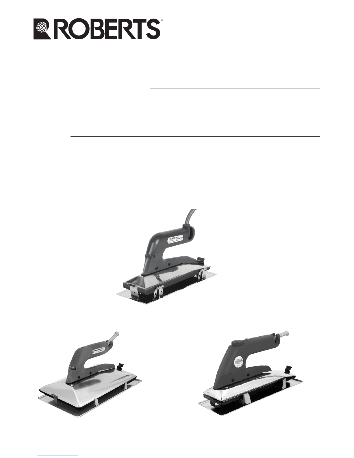
Heat Bond Tape Seaming Iron
OWNER’S MANUAL
Fer de couture pour ruban à
adhésion thermique
MANUEL DU PROPRIÉTAIRE
Plancha para unir con cinta
adhesiva al calor
MANUAL DEL USUARIO
10-482G
10-286G
10-282G-2
– 2 –
GENERAL SAFETY RULES
Read and understand all instructions. Failure to follow the
instructions listed below may result in electric shock, fire, serious personal
injury, or damage to carpet.
SAVE THESE INSTRUCTIONS
Work Area
Do not expose tools to rain. Do not use tools in a damp or wet location.
Keep your work area clean and well lit. Do not use tools in the presence of
flammable liquids or gases.
Personal Safety
Stay alert, watch what you are doing and use common sense when operating
electrical tools. Do not use tool while tired or under the influence of drugs,
alcohol or medication. Dress properly. Do not wear loose clothing or jewelry.
Keep long hair, clothing and jewelry away from moving parts. Avoid touching
the heat shield or base when using the iron. Wear gloves when seaming.
TOOL USE AND CARE
This iron is used for melting adhesive on Heat Bond Carpet
Seaming Tape. It is not intended for any other use.
The handle of the iron is molded from a very durable fiberglass filled nylon
material. The base is a non-stick coated die-cast aluminum and the iron is
equipped with an insulated stainless steel heat shield.
It runs on 120-volt standard U.S. electrical current. Do not change cords,
plugs or electrical components. Take the iron to an authorized repair shop for
repairs. Do not pull the plug from the socket with the cord. Grasp the plug
and pull from the socket. This iron is intended for indoor use only.
Extension Cords
Only use extension cords that are intended for indoor use. These extension
cords are identified by the statement: “Acceptable for use with indoor
appliances; store indoors while not in use”. Only use extension cords having
an electrical rating that is higher than the rating of the product. Do not use
damaged extension cords. Examine extension cord before using and replace
if damaged. Do not abuse extension cords and do not yank on any cord to
disconnect. Keep cord away from heat and sharp edges. Always disconnect
the extension cord from the receptacle before disconnecting the product from
the extension cord.
– 3 –
WARNING - To reduce the risk of electrocution, keep all connections dry and
off the ground. Do not touch plug with wet hands.
USING YOUR ROBERTS SEAMING IRON
1. Select a clear area near the beginning of your seam to place your iron for
heating. Set the iron in its base and place the base on a solid surface,
such as a piece of plywood or a piece of scrap carpet.
2. Make sure your extension cord is long enough to reach the end of your
seam. Place all required materials and tools within reach.
3. Plug the iron into a household (120-volt) socket and set the thermostat
control located on the front of the handle to your desired temperature
setting. Consult your tape manufacturer’s instructions for the proper heat
range. The chart below shows the thermostat knob settings for various
temperature ranges.
Number
on Knob
Temperature Range
Time to Reach
Temperature
Min ˚C Max ˚C Min ˚F Max ˚F
1 52˚C 72˚C 125.6˚F 161.6˚F 1-1/2 minutes
1-1/2 76˚C 107˚C 170˚F 224˚F 2 minutes
2 100˚C 123˚C 212˚F 253.4˚F 2-1/2 minutes
2-1/2 129˚C 161˚C 266˚F 322˚F 3 minutes
3 166˚C 186˚C 330.8˚F 366.8˚F 3-1/2 minutes
3-1/2 170˚C 203˚C 339˚F 396˚F 3-3/4 minutes
4 200˚C 220˚C 392˚F 428˚F 4 minutes
4. Allow the iron to reach operating temperature, according to the
approximate time chart above. Let the iron cycle several times before
you begin seaming. The light on top of the handle will stay red while the
iron is reaching your desired temperature. The light will turn green when
the iron has reached the correct temperature.
5. Test the iron for proper temperature on your tape or a piece of scrap
tape to get the desired melting of the adhesive.
NOTE: For Roberts Heat Bond tapes, we recommend a setting of 2
or 3 on the temperature control knob.
– 4 –
MAINTENANCE OF NON-STICK COATED BASE PLATE
1. The base plate is coated with a tough non-stick coating, to provide a long
lasting easy to clean surface. To preserve this finish, please follow these
steps:
b. Always put the iron in its holder when not seaming.
c. Never try to clean the base with a wire brush, knife or
any hard material.
d. Do not place your iron on concrete or other hard surfaces.
Put the iron in its holder, when storing it in your toolbox.
e. ALWAYS CLEAN YOUR IRON AFTER A JOB.
2. To clean your iron, rub the base over a piece of clean carpet scrap while
the iron is still hot.
Specifications
10-282G-2, 10-286G and1 10-482G
Amps 6.6A
Watts 800W
Approx Heat Range 125.6° F ~ 428° F (52° C ~ 220° C)
Volts ~120
– 5 –
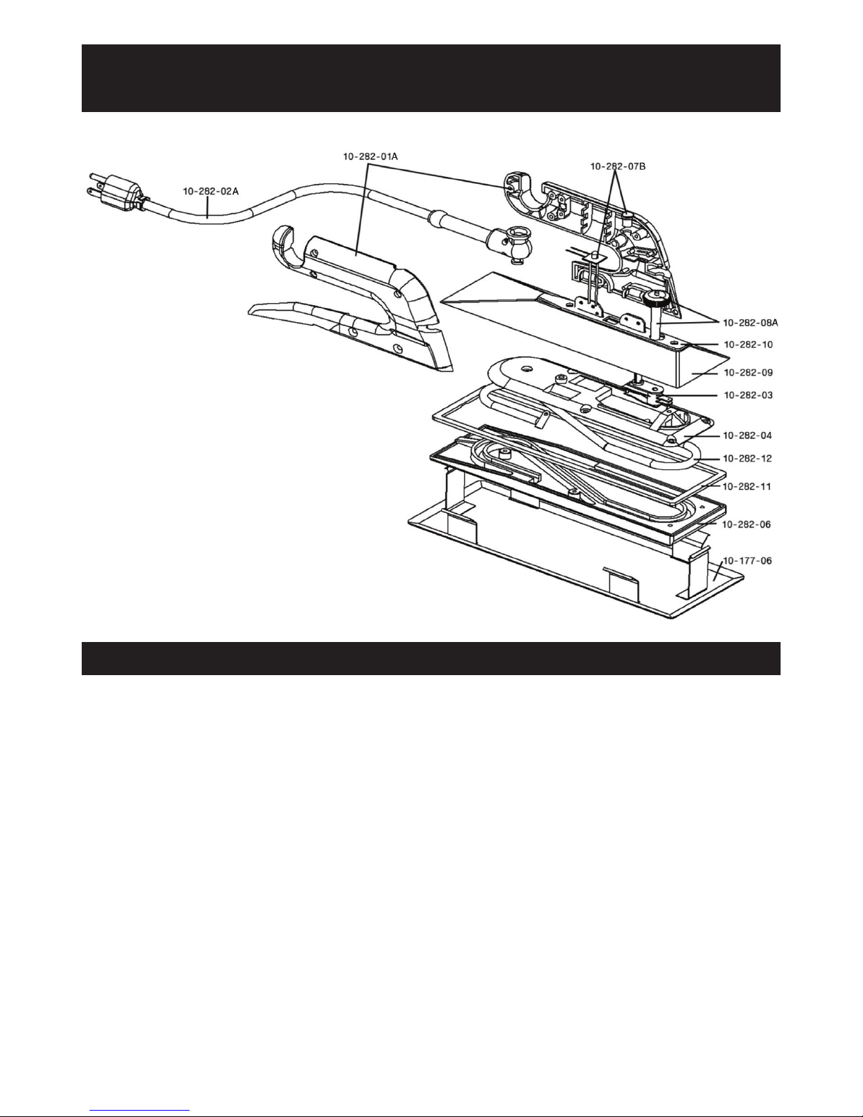
REPLACEMENT PARTS LIST
Part Description
10-282-01A
10-282-02A
10-282-03
10-282-04
10-177-06
10-282-06
10-282-07B
10-282-08A
10-282-09
10-282-10
10-282-11
10-282-12
10-282-13
10-282-14
10-282-15
Handle Set w/ (8) Screws
Cord Set Includes Cord Relief Spring, Wire Connection Clip and (4) Screws
Thermostat w/ Extension Post for Control Knob
Top Sole Plate w/ (5) Screws
Iron Holder
Bottom Sole Plate, Non-stick, Grooved (not pictured)
Internal Wire Set (2 pieces)
Calibration Knob
Heat Shield w/ (2) Screws and (1) Washer
Gasket (top of Heat Shield for Handle Mount)
Gasket (between Heat Shield and top of Sole Plate)
Heating Element
Fused Wire Assembly (not pictured)
(50) Screws for Handle (not pictured)
(50) Screws For Sole Plate & Heat Shield (not pictured)
ROBERTS 10-282G-2
DELUXE HEAT BOND IRON
– 6 –
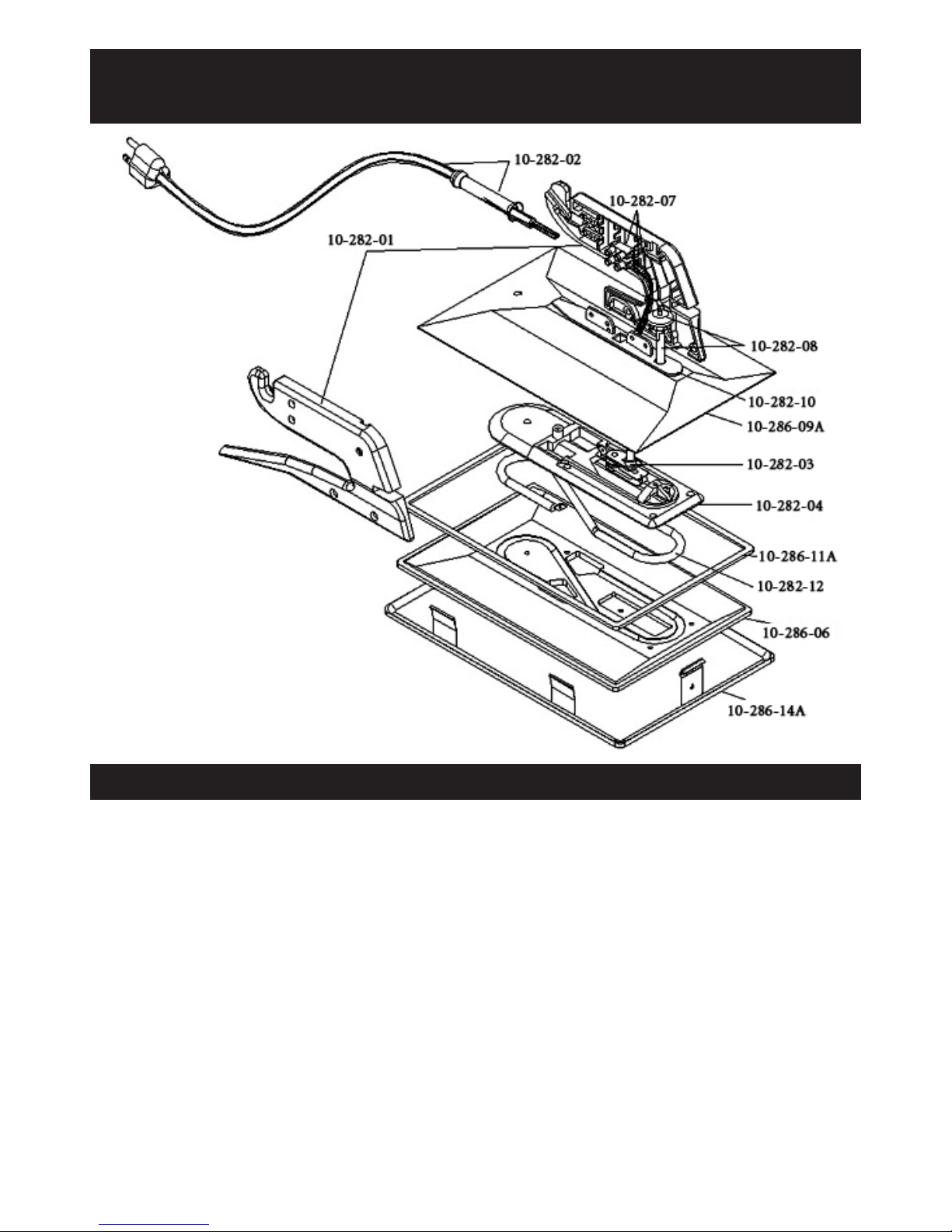
REPLACEMENT PARTS LIST
Part Description
10-282-01
10-282-02
10-282-03
10-282-04
10-286-06
10-282-07
10-282-08
10-286-09A
10-282-10
10-286-11A
10-282-12
10-282-13
10-286-14A
10-282-14
10-282-15
Handle Set w/ (7) Screws
Cord Set w/ Cord Relief Spring, Wire Connection Clip & (2) Screws
Thermostat w/ Extension Post for Control Knob
Top Sole Plate w/ (5) Screws
6” Bottom Sole Plate, Non-stick, Grooved
Internal Wire Set (2 pieces)
Calibration Knob
Heat Shield w/ (2) Screws & (1) Washer
Gasket (top of Heat Shield for Handle Mount)
Gasket (between Heat Shield & top of Sole Plate)
Heating Element
Fused Wire Assembly (not pictured)
Iron Holder
(50) Screws For Handle (not pictured)
(50) Screws for Top Sole Plate & Heat Shield (not pictured)
ROBERTS 10-286G
HEAT BOND IRON
– 7 –
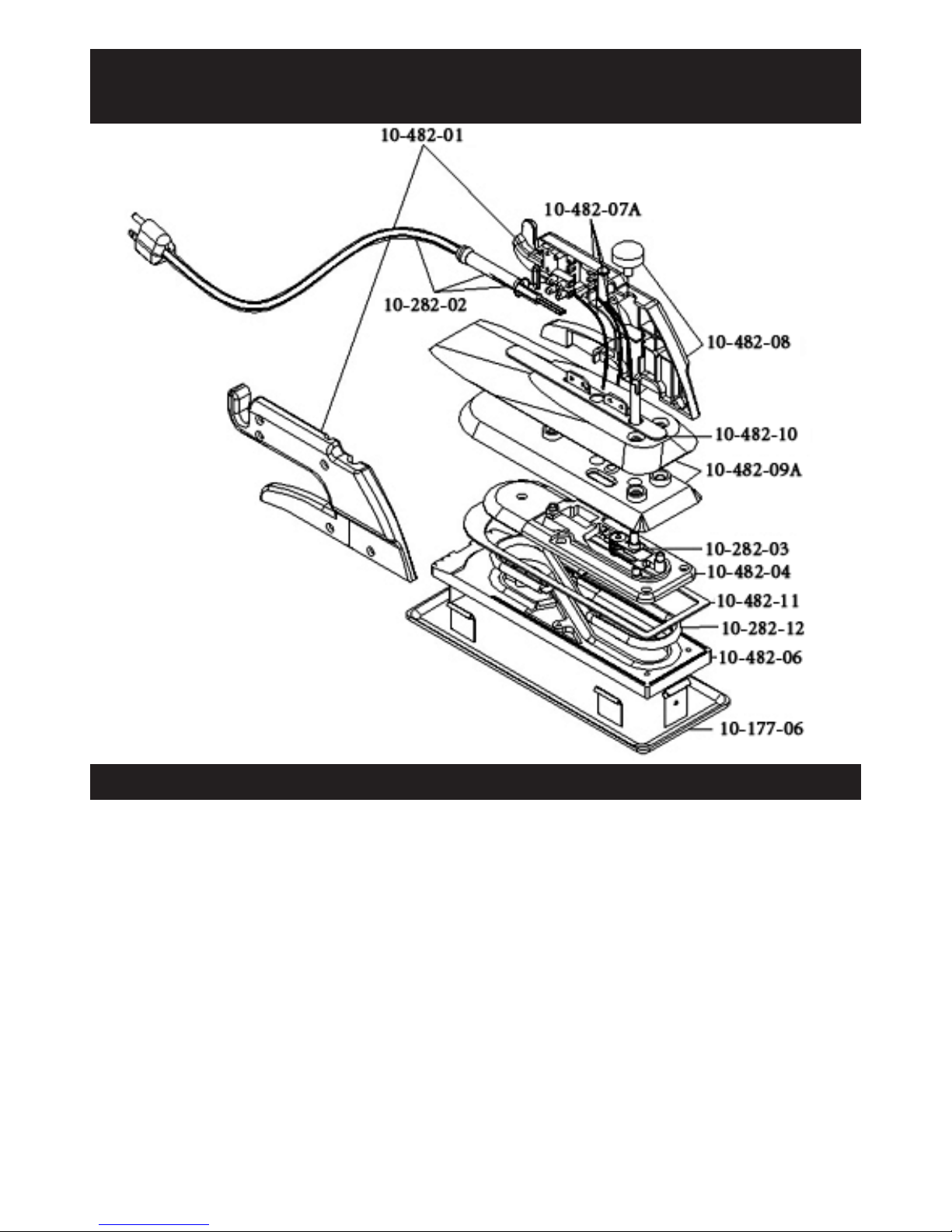
REPLACEMENT PARTS LIST
Part Description
10-482-01
10-282-02
10-282-03
10-482-04
10-177-06
10-482-06
10-482-07A
10-482-08
10-482-09A
10-482-10
10-482-11
10-282-12
10-482-13A
10-482-14
10-282-15
Handle Set w/ (7) Screws
Cord Set w/ Cord Relief Spring, Wire Connection Clip & (2) Screws
Thermostat w/ Extension Post for Control Knob
Top Sole Plate w/ (5) Screws
Iron Holder
Bottom Sole Plate, Non-stick, Grooved
Internal Wire Set (2 pieces)
Calibration Knob
Heat Shield w/ (2) Screws & (1) Washer
Gasket (top of Heat Shield for Handle Mount)
Gasket (between Heat Shield and top of Sole Plate)
Heating Element
Fused Wire Assembly (not pictured)
(50) Screws For Handle (not pictured)
(50) Screws for Top Sole Plate & Heat Shield (not pictured)
ROBERTS 10-482G
COOL SHIELD IRON
 Loading...