

Page 1
Version 1.
2
Page 2

Strobe IP
2
Table of contents
1. Safety instructions ...................................................................................................................................................... 3
2. Fixture exterior view ................................................................................................................................................... 5
3. Installation .................................................................................................................................................................. 5
3.1 Connection to mains ............................................................................................................................................. 5
3.2 Mounting the fixture ............................................................................................................................................ 5
3.3 DMX 512 connection ............................................................................................................................................ 7
4. Control menu .............................................................................................................................................................. 8
4.1 Fixture Address ..................................................................................................................................................... 8
4.2 Fixture information ............................................................................................................................................... 8
4.3 Personality ............................................................................................................................................................ 9
4.4 Manual mode ...................................................................................................................................................... 10
4. 5 Test sequences................................................................................................................................................... 10
4.6 Stand-alone setting ............................................................................................................................................. 10
4.7 Special functions ................................................................................................................................................. 11
5. Strobe and Special effects running ........................................................................................................................... 13
5.1 Strobe ................................................................................................................................................................. 13
5.2 Special effects ..................................................................................................................................................... 13
6. Technical specifications ............................................................................................................................................ 16
7. Cleaning and maintenance ....................................................................................................................................... 19
7.1 Replacing a fuse .................................................................................................................................................. 19
7.2 Disposing of the product .................................................................................................................................... 19
Page 3

Strobe IP
3
FOR YOUR OWN SAFETY, PLEASE READ THIS USER MANUAL CAREFULLY
BEFORE POWERING OR INSTALLING YOUR Strobe IP!
Save it for future reference.
This device has left our premises in absolutely perfect condition. In order to maintain this condition and to ensure
safe operation, it is absolutely necessary for the user to follow the safety instructions and warnings written in this
manual.
The manufacturer will not accept liability for any resulting damages caused by the non-observance of this manual
or any unauthorized modification to the device.
Unauthorized modification will void warranty.
This device is for professional use only. It is not for household use.
1. Safety instructions
DANGEROUS VOLTAGE CONSTITUTING A RISK OF ELECTRIC SHOCK IS PRESENT WITHIN THIS UNIT!
Make sure that the available voltage is not higher than stated on the rear side of the fixture.
This fixture should be operated only from the type of power source indicated on the marking label. If you are not
sure of the type of power supplied, consult your authorized distributor or local power company.
Always disconnect the fixture from AC power before servicing or cleaning internally.
Do not overload supply line as this can result in fire or electric shock.
Make sure the power/data cable is never crimped or damaged by sharp edges. Check the fixture and the
power/data cable from time to time.
Do not install the unit near an open flame.
Refer servicing to qualified service personnel.
Do not connect this fixture to a dimmer pack.
WARNING! This unit does not contain an ON/OFF switch. Always disconnect power input cable to completely
remove power from unit when not in use or before cleaning or servicing the fixture.
This fixture falls under protection class I. Therefore, this fixture has to be connected to a mains socket outlet
with a protective earthing connection.
Warning! Risk Group 2 LED product according to EN 62471.
LED light emission. Risk of eye injury.
Do not look straight at the fixture´s LEDs during operation. The intense light beam may damage your eyes.
Keep combustible material at least 0.3 m away from the fixture.
Page 4

Strobe IP
4
If the fixture has been exposed to drastic temperature fluctuation (e.g. after transportation), do not switch it on
immediately. The arising condensation of water might damage your device. Leave the device switched off until it
has reached room temperature.
Avoid brute force when installing or operating the fixture.
To guard against epileptic seizure:
Do not operate the fixture near stairways. Provide advance notice that strobe lighting is in use. Avoid extended
periods of continuous flashing, particularly at frequencies of 10 to 20 flashes per second
When choosing the installation spot, please make sure that the fixture is not exposed to extreme heat or dust.
Avoid using the unit in locations subject to possible impacts.
Only operate the fixture after having checked that the housing is firmly closed and all screws are tightly fastened.
Do not block the front glass cover with any object when the fixture is under operation.
The fixture body must never be covered with cloth or other materials.
The fixture becomes very hot during operation. Allow the fixture to cool approximately 30 minutes prior to
manipulate servicing or maintenance.
Operate the fixture only after having familiarized yoursef with its functions. Do not permit operation by persons
not qualified to operate the fixture. Most damages are the result of unprofessional operation!
Please consider that unauthorized modifications on the fixture are forbidden due to safety reasons!
Please use the original packaging if the fixture is to be transported.
If this device will be operated in any way different to the one described in this manual, the product may suffer
damages and the warranty becomes void. Furthermore, any other operation may lead to dangers like short-circuit,
burns, electric shock etc.
Page 5
Strobe IP
5
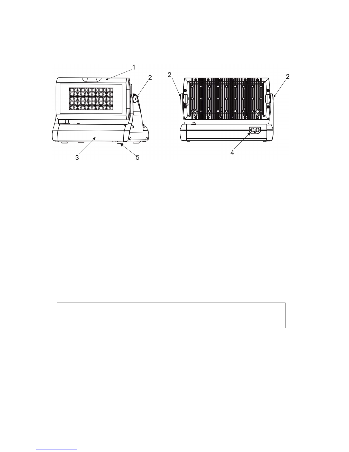
2. Fixture exterior view
3. Installation
3.1 Connection to mains
Fixtures must be installed by a qualified electrician in accordance with all national
and local electrical and construction codes and regulations.
This device falls under class one and must be grounded!
The Strobe IP is equipped with auto-switching power supply that automatically adjusts to any 50-60Hz AC power
source from 100-240V (CE) or 100-277 V (US). The fixture must be connected to a non-dimmable power source in
order to avoid damage to its internal power supply and other electrical components.
Connect the fixture to the mains by means of inbuilt power cord with the plug.
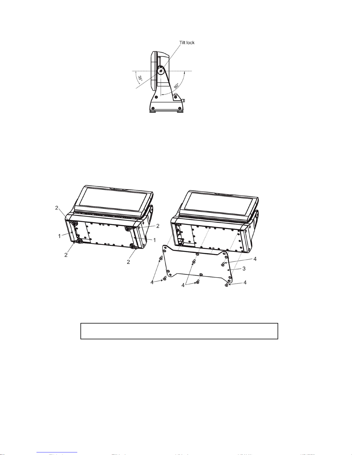
3.2 Mounting the fixture
The Strobe IP can be arranged in any position/orientation without altering its operation characteristics. The LED
module can be tilted to desired position by means of the tilt lock. Use an Allen key 6 to adjust desired tilt position.
1.
Head with LED array
2. Tilt lock
3. Base
4. Power and DMX connection
5. Rubber legs
Page 6
Strobe IP
6
The fixture is equipped with two pairs of rubber legs for standing on the floor or can be fastened on a nonflammable surface by means of the Surface Mount Adapter Strobe IP (optional accessories).
Before installing the Surface Mount Adapter Strobe IP (1), remove both rubber legs holders (1) by unscrewing the
four screws (2).
Screw the mounting adapter (3) to the base of the fixture by means of the six screws M8x20 (4).
Ensure that the structure to which you are attaching
the fixture is secure.
Caution: Overhead installation requires experience. Fixtures may cause severe injuries when crashing down! If you
have doubts concerning the safety of a possible installation, do not install the device and consult installation with
an expert.
Page 7
Strobe IP
7
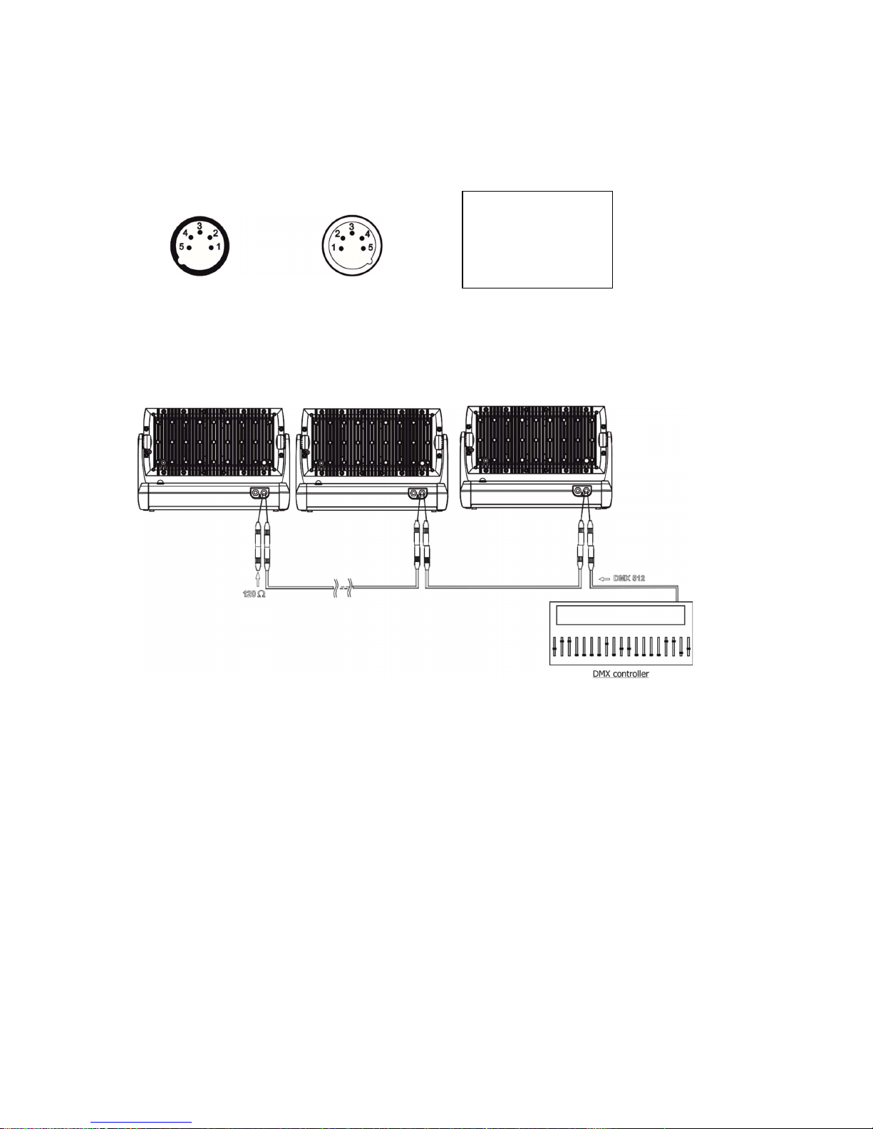
3.3 DMX 512 connection
The fixture is equipped with 5-pin XLR connectors for DMX input/output. Only use a shielded twisted-pair cable
designed for RS-485 and 5-pin XLR connectors in order to connect the controller with the fixture or one fixture
with another.
Wiring of the XLR connectors:
XLR socket: XLR plug:
To build a DMX chain
1. Connect the DMX output of the controller directly with the DMX input of the first fixture in the DMX chain.
2. Connect the DMX output of the first fixture in the DMX chain with the DMX input of the next fixture.
3. Always connect the DMX output with the input of the next fixture until all fixtures are connected.
Do not overload the link. Max. 32 fixtures may be connected on a DMX link.
Caution: Terminate the link by installing a termination plug in the output of the last fixture. The termination plug is
a male 5-pin XLR plug (IP 66 rating) with a 120 Ohm resistor soldered between Signal (–) and Signal (+).
Warning:
Fixture´s XLR connectors are dust and water protected according to IP 67 by mating with related XLR cable
connectors.
They cannot stay disconnected outdoor. DMX output connector (XLR female) at the last fixture in a DMX line
has to be covered with the rubber cap before inserting a terminator. The rubber cap does not supply the
terminator.
The XLR terminator (male) has to be dust and water protected.
If the fixture is to be outdoor without connecting to DMX line, always interconnect its DMX input with DMX output
to keep declared IP rating of XLR connectors.
1 – Shield
2 - Signal (-)
3 - Signal (+)
4 – Not connected
5 – Not connected
Page 8

Strobe IP
8
4. Control menu
The Strobe IP is equipped with a 4-segment LED display which allows you to set the fixture´s behaviour according
to your needs, obtain information on its operation, control all range of effects and program it
in stand-alone mode.
The four control buttons have the following functions:
- ESCAPE button-leaves menu without saving changes.
- ENTER button- enters menu, confirms adjusted values and leaves menu.
- UP and - DOWN buttons - move between menu items on the same level, sets values.
After switching the fixture on, display shows current DMX address.
4.1 Fixture Address
Use this menu to set the DMX address of the fixture.
dM.Ad. --- DMX addressing. Select this submenu to set a DMX start address.
To set a DMX address.
1. Use UP/DOWN buttons to find “ A001“ menu.
2. Press the ENTER button.
3. Use the UP/DOWN buttons to select desired start address.
4. Press the ENTER button to confirm the choice.
Note: After switching on, the Strobe IP will automatically detect whether DMX 512 data is received or not.
If there is no data received at the DMX input, the display will start to flash the set address.
DM.Pr. --- DMX preset. Select this menu item to set a desired DMX mode.
4.2 Fixture information
Use this menu to read useful information about the fixture status.
To display desired information.
1. Use the UP/DOWN buttons to find the “ InFo“ menu.
2. Press the ENTER button.
3. Use the UP/DOWN buttons to select the required menu item.
4. Press the ENTER button to confirm the choice.
Po.ti. --- Power On Time. Use the menu item to read the number of operation hours of the fixture.
totL - the function shows the total number of the operation hours since the Strobe IP has been fabricated.
rESEt - the function shows the number of the operation hours since the counter was last reset.
In order to reset this counter to 0, you have to press and hold the UP and DOWN buttons and at the same
time press the ENTER button.
VErS. ---Software Versions. Select this function to read the software version of the fixture processors.
ICI.b. --- display processor 1
IC2.b. --- display processor 2
Page 9
Strobe IP
9
IC3.L. --- LED processor 3
IC4.L. --- LED processor 4
ViFi --- Wireless DMX module (if installed)
tEMP --- Fixture Temperatures. Select this menu to read the temperatures of the fixture:
bASE. --- temperature of the fixture inside
Cur.t. --- the current temperature of the fixture inside.
Hi.tE. --- the menu item shows the max. temperatures of the fixture inside since
the fixture has been fabricated.
rSEt --- the menu item shows the maximum temperatures of the fixture inside since the counter
was last reset. In order to reset this counter to 0 you have to press and hold the UP and DOWN
buttons and at the same time press the ENTER button.
LEdS. --- temperature of the LEDs PCB.
Cur.t. --- the current temperature of the LEDs PCB.
Hi.tE. --- the menu item shows the max. temperatures of the LEDs PCB since
the fixture has been fabricated.
rSEt --- the menu item shows the maximum temperatures of the LEDs PCB since the counter
was last reset. In order to reset this counter to 0 you have to press and hold the UP and DOWN
buttons and at the same time press the ENTER button.
dM.In.---DMX values. Select this function to read DMX values of each channel received by the fixture.
4.3 Personality
Use this menu to modify the Strobe IP operating behaviour.
DM.Pr. --- DMX preset. Select this menu item to set a desired DMX mode. Please refer to the chapter "DMX
protocol" for detail description of each DMX mode.
dM.In. --- DMX input. Select this menu item to select desired DMX input:
UirE --- Wired DMX.
UirL --- Wireless DMX
UrLo --- Wireless DMX –> wired DMX. The fixture receives wireless DMX signal and sends it to its
DMX output connector. Next fixtures can be connected to this fixture by DMX cable (fixture works
as a Wireless-DMX converter.
F.tin. --- Max. Fade time. Select this menu item to set a desired max. fade time (0-25.4 sec.). This adjusted fade
time influences fade of dimmer during DMX operation:
If time between two receiving DMX values is > than fade time set in the item “M Ftime“, the entire adjusted fade
time will be used.
If time between two receiving DMX values is < than fade time set in the item“M Ftime“, the adjusted fade time will
be reduced to fill entire time between the two receiving DMX values.
e.g “F.tin“=2sec. and fixture has received dimmer=0 DMX, after 5 seconds will receive dimmer=255 DMX. It means,
that dimmer will go to full intensity during 2 seconds.
“F.tin.“=8 sec. and fixture has received dimmer=0 DMX, after 5 seconds will receive dimmer=255 DMX. It means,
that dimmer will go to full intensity during 5 seconds. (Max, fade time is reduced from 8 sec. to 5 sec.).
DiSP. --- Display adjusting. This function allows you to change the display settings.
d.On --- this function allows you to keep the display on or to turn off automatically 2 minutes
after last pressing any button on the control panel.
Page 10
Strobe IP
10
d.Int. --- select this function to adjust the display intensity (6-min.,100-max.).
turn ---
select this function to used to rotate menu 180 degrees from current orientation
.
di M.c. --- Dimmer curve. Use this menu item to set desired dimmer curve:
Lin --- linear
SqL --- square law
tnP.u. --- Temperature unit. Use this menu in order to display the fixture temperatures in desired units: °C or °F.
In.Po. --- Init effect positions. Use this function to set all effects to the desired positions to which they will move
after switching the fixture on (without DMX signal).
dF.SE. --- Default Settings .The menu item sets all fixture parameters to the default (factory) values.
4.4 Manual mode
Use this menu to control all channels via buttons of the control board.
Items in this menu depend on selected DMX mode.
To control fixture channels.
1. Use the UP/DOWN buttons to find “ Man.C“ menu.
2. Press the ENTER button.
3. Use the UP/DOWN buttons to select desired effect (channel).
List of control channels:
“dinr“ - a coarse dimmer
“din.F” a fine dimmer
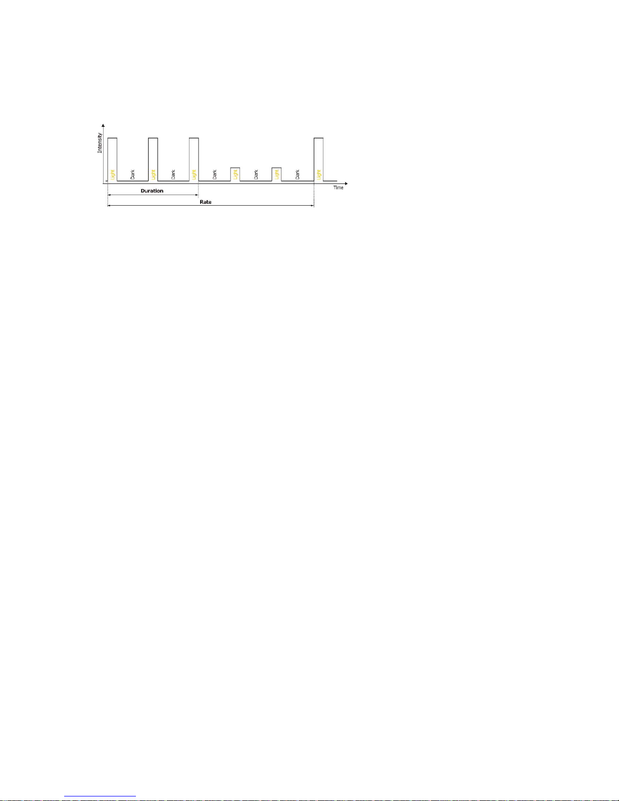
“dUrA.” – a duration
“rAtE.” – a rate
“SP.EF.” – special effects
“SP. FU.” – special functions
“Zo.EF.” – zone effects
“Z.E.SP.” – a zone effects speed
“CoL. 1” – a zone 1 intensity
“CoL. 2” – a zone 2 intensity
“CoL. 3” – a zone 3 intensity
“CoL. 4” – a zone 4 intensity
“CoL. 5” – a zone 5 intensity
“CoL. 6” – a zone 6 intensity
4. Press the ENTER button and use the UP/DOWN buttons to set value , press the ENTER button to confirm it.
4. 5 Test sequences
Use this menu to run demo-test sequences without an external controller, which will show you some possibilities
of using the Strobe IP.
4.6 Stand-alone setting
Page 11

Strobe IP
11
The fixtures on a data link are not connected to the controller but can execute pre-set programs which can be
different for every fixture. “Stand-alone operation” can be applied to the single fixture or to multiple fixtures
operating synchronously.
Auto. --- Automatic playback. This function allows you to select the program which will be played after switching
the fixture on. Selected program will be played continuously in a loop.
1. Use the UP/DOWN buttons to select test program (“tESt”), user program (“u.PrG”) or disable this function
(OFF).
2. Press the ENTER button to confirm the choice.
PLAY --- Playing program. Entering this menu provides a complete overview of all programs offered, from which
the selected program can run.
1. Use the UP/DOWN buttons to select desired program.
2. Press the ENTER button. The selected program runs in a loop.
Edit --- Editing a program. The fixture offers a freely editable program up to 40 steps. Every program step includes
a step time-the total time occupied by the step in the program.
1. Use the UP/DOWN buttons to select a desired program step ("St.01" - "St.40") and press ENTER button.
2. Use the UP/DOWN buttons to select a channel you want to edit and press the ENTER button.
List of editable items:
“P.End” - a total number of the program steps (value 1-40). This value should be set before start of
programming (e.g. if you want to create a program with 10 steps, set P.End=10).
“dinr“ - a coarse dimmer
“din.F” a fine dimmer
“dUrA.” – a duration
“rAtE.” – a rate
“SP.EF.” – special effects
“SP. FU.” – special functions
“Zo.EF.” – zone effects
“Z.E.SP.” – a zone effects speed
“CoL. 1” – a zone 1 intensity
“CoL. 2” – a zone 2 intensity
“CoL. 3” – a zone 3 intensity
“CoL. 4” – a zone 4 intensity
“CoL. 5” – a zone 5 intensity
“CoL. 6” – a zone 6 intensity
“F.tin.” – fade time
“S.tin” – step time
“COPY“. – this item duplicates the current prog. step to the next prog. step.
Note: Items in this menu depend on selected DMX mode.
3. Use the UP/DOWN buttons to set a DMX value of the channel and then press the ENTER button.
4. Use the UP/DOWN buttons to select next channel and press the ENTER button.
5. After having set all channels in the current program step, press the ESCAPE button to go one menu level
back and select another program step.
4.7 Special functions
rdM.L --- Code.This menu item shows the first part of the RDM identification code.
Page 12

Strobe IP
12
rdM.H --- Code. This menu item shows the second part of the RDM identification code.
UiFi --- Wireless DMX. The menu serves for reading of the wireless operation status (only for Wireless DMX
version).
50 --- Wireless DMX signal intensity. The menu item shows level of received signal in %. If the fixture is not
linked to the transmitter, “niSS” is displayed.
UnLI --- Wireless DMX unlink. The item serves for unlinking the fixture from transmitter.
uPd.M. --- Updating mode. The menu item allows you to update software in the fixture via either serial or USB port
of PC.
The following are required in order to update software:
- PC running Windows 7/8/10 or Linux
- DMX Software Uploader
- Flash cable RS232/DMX P/N.13050624 (if you want to use serial port of PC)
- Robe Universal Interface (if you want to use USB port of PC)
Note: Software update should be executed by a qualified person. If you lack qualification, do not attempt the
update yourself and ask for help from your Robe distributor.
DMX address, user program and all items in the menu "PerS" will be set to their default (factory) values.
To update software in the fixture:
I. Installation of the DMX Software Uploader.
1. DMX Software Uploader program is available from the Robe web site at WWW.robe.cz.
2. Make a new directory ( e.g. Robe Uploader) on your hard disk and download the software to it.
3. Unpack the program to the directory.
II. Fixture software updating.
1.Determine which of your ports is available on your PC and connect it:
- with the DMX input of the fixture if you are using the flash cable RS232/DMX
- with the DMX output of the Robe Universal Interface if you are using the USB cable.
Disconnect the fixture from the other fixtures in the DMX chain. Turn both the computer and
the fixture on. Make sure the lamp is switched off (only if the fixture involves a lamp).
2. Switch the fixture to the updating mode by selecting the "uPd.M." item and then selecting “yES“.
Note: If you do not want to continue in software update, you have to switch the fixture off and on
to escape from this menu.
We recommend canceling all running programs before starting the Software Uploader.
3. Run the Software Uploader program. Select desired COM and then click on the Connect button.
(Select COM if the serial port is used or Robe Universal Interface if the USB port is used).
If the connection is OK, click on the “Start Uploading button“ to start uploading. It will take several
minutes to perform software update.
If the option "Incremental Update" is not checked, all processors will be updated (including
processors with the same software version).
If you wish to update only later versions of processors, check the “Incremental Update box“.
Avoid interrupting the process. Update status is being displayed in the Info Box window.
When the update is finished, the line with the text “The fixture is successfully updated“ will appear in
this window and the fixture will reset with the new software.
Note: In case upload process is interrupted (e.g. power loss), the fixture stays in “Updating mode” and you will
have to repeat the software update again.
Page 13
Strobe IP
13
5. Strobe and Special effects running
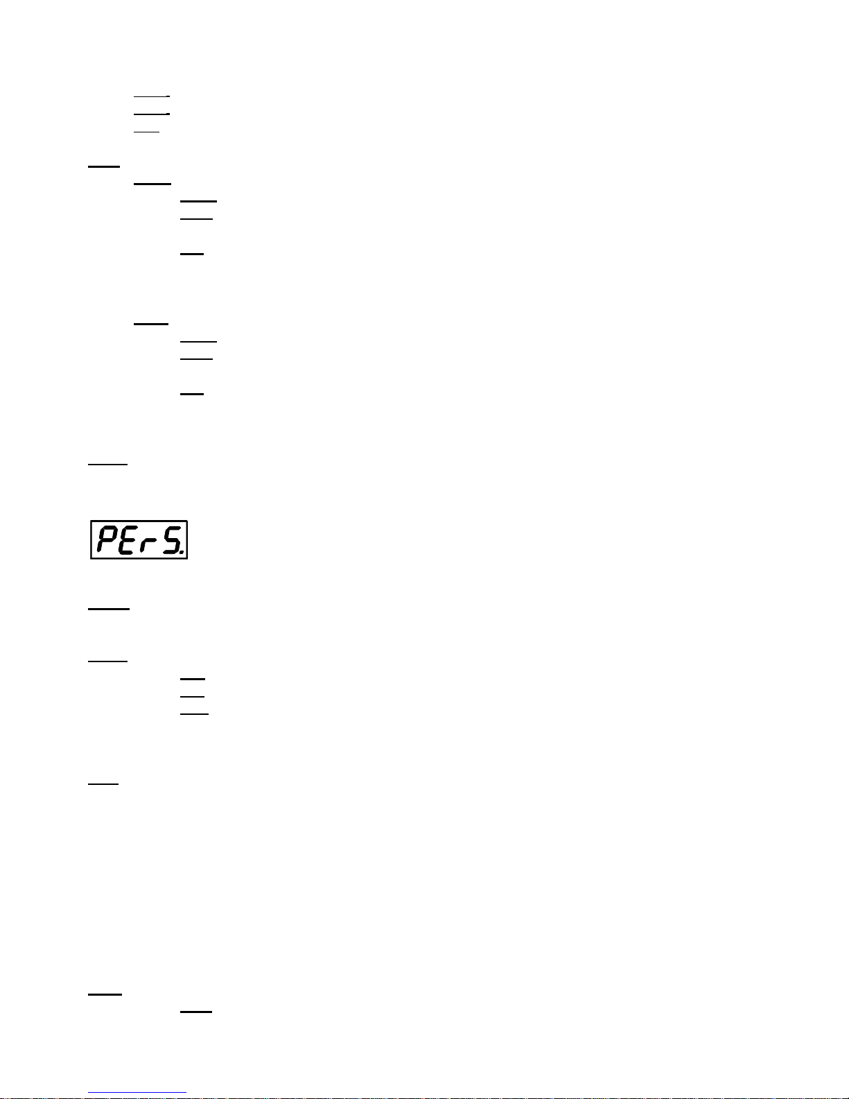
5.1 Strobe
Mode 1 and 2
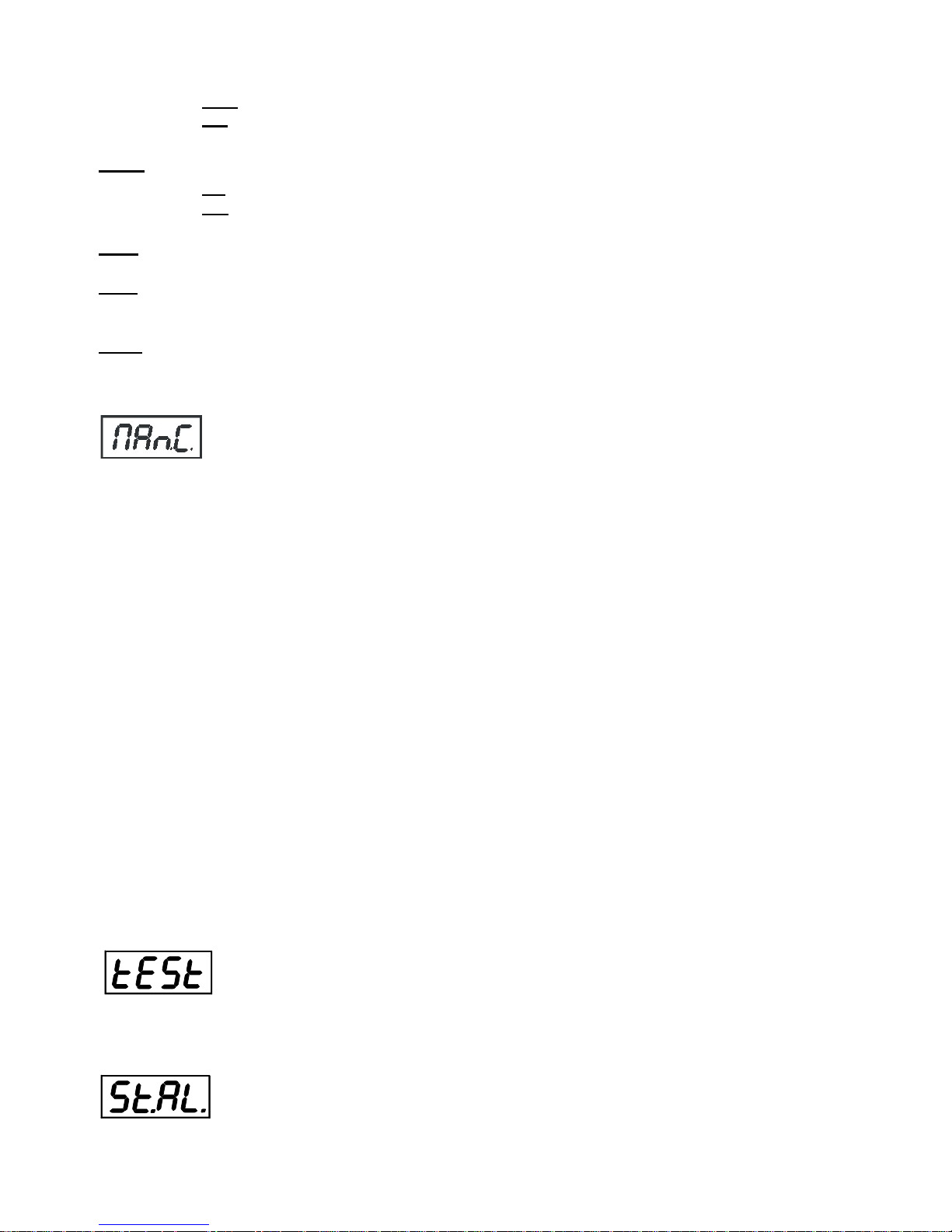
Mode 3 and 4
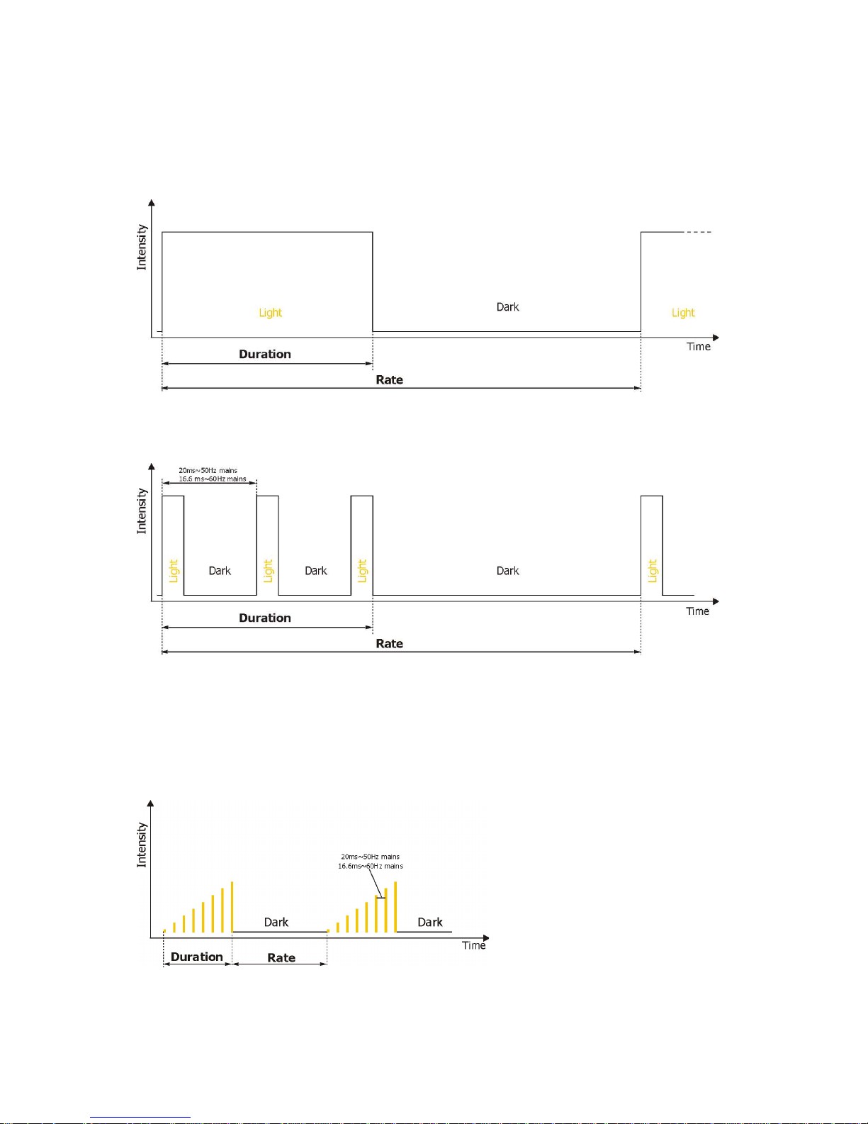
5.2 Special effects
Rumping
Rump Up
Page 14
Strobe IP
14
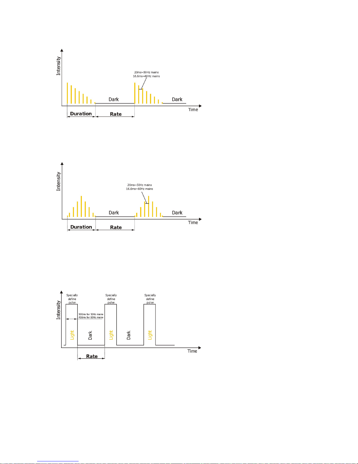
Rump Down
Rump Up/Down
Lightning
Mode 1, 2, 4
Page 15
Strobe IP
15
Spikes
For Duration and Rate timing serves the same values as for strobe
Page 16

Strobe IP
16
6. Technical specifications
Power supply
• Electronic auto-ranging
• Input voltage (EU): 100 - 240V AC, 50-60 Hz
• Input voltage (US): 100 - 277V AC, 50-60 Hz
• Max. power consumption: 180 W
• Inrush current: 20A (at 230V), 30A (at 115V)
Optic & Effects
• Light source: 60 x high power CW LED
• Beam angle: 32°
• 6 LED zones
•Min. LED life expectancy: 20,000 hours
Zone effects
•Zone effects in both directions with variable speed
Strobe
•Strobe effect with variable speed
•Pulses adjustment: frequency, duration, intensity
•Special effects: rump up, rump down, rump up/down, random, lighting, spikes
Dimmer
• Smooth 16-bit dimming from 0 - 100 %
Control
• Setting & Addressing: 4-segment LED display & 4 control buttons
• Control: USITT DMX 512 (RDM support)
• DMX protocol modes: 4 (8,14,3,4 control channels)
• Operations modes: DMX, Stand-alone
• Manual control of all effects via control panel
• One editable program, up to 40 steps
Wireless DMX/RDM module (only for wireless DMX version of the Strobe IP)
• Compliance with USITT DMX-512 (1986 & 1990) and 512-A
• Full DMX fidelity and frame integrity
• Auto sensing of DMX frame rate and frame size
• <5ms DMX latency
• Operational frequency range of 2402-2480 MHz
• Producer: LumenRadio
Connection
• 2x Outdoor DMX cable CA-0611 + 2x 5-pin XLR (male,female IP 67)
• 1x mains cable with plug
Mounting
• Via mounting adapter
Protection factor
• EU: IP 67 (except power plug)
• US: Suitable for wet location (Except power plug)
Page 17

Strobe IP
17
Temperatures
• Operating Ambient Temperature: -20°C / +40°C (-4°F / +104°F )
• Operating Temperature: +70°C @ Ambient +40°C (+158°F @ Ambient +104°F )
Minimum distances
• Min. distance from flammable material: 0.3 m
• Min. distance of illuminated objects: 2 m
Total heat dissipation
• 680 BTU/h (calculate)
Weight
• 14.1 kg
Dimensions
mm [inch]
Fixture with installed Surface Mount Adapter Strobe IP
Page 18

Strobe IP
18
Photometric diagrams
Included items
• 1 x Strobe IP
• 1 x Set of rubber feet black (P/N 10980370)
• 1 x User manual
OptionaI accessories
• Surface Mount Adapter Strobe IP, black (P/N10980347)
• Top Hat Strobe IP black (P/N 10980354)
• Half Top Hat Strobe IP black (P/N 10980355)
• Barndoor Module Strobe IP black (10980356)
• C-Clamp Adaptor Strobe IP/Divine, black (P/N 10980324)
• Gel Frame Strobe IP black (10980364)
Page 19

Strobe IP
19
7. Cleaning and maintenance
DANGER !
Disconnect from the mains before starting any cleaning or maintenance work
Rinse off loose dirt with low pressure water spray. Wash the housing with a soft brush or sponge and a mild, nonabrasive washing detergent. Rinse it.
Maintenance and service operations are only to be carried out by a qualified person.
Should you need any spare parts, please use Robe OEM parts.
7.1 Replacing a fuse
This replacement has to be done by a qualified person or Robe service worker only.
7.2 Disposing of the product
To preserve the environment please dispose or recycle this product at the end of its life according to the local
regulations and codes.
Specifications are subject to change without notice
May 19, 2017
Copyright © 2017 Robe Lighting - All rights reserved
Made in ROBE Lighting s.r.o., Palackého 416, 757 01 Valašské Meziříčí, Czech Republic
Page 20

DMX protocol
Version: 1.1
1 2 3 4
1 1 1 1
Intensity (8bit)-all zones
0-5 Closed (mode 3,4 only) step
6-255 Coarse intensity from min. to max. (Mode 3,4 only) proportional
0-255 Coarse intensity from min. to max. (Mode 1,2 only) proportional
2 2 * *
Intensity (16bit)-all zones
0-255 Fine intensity from min. to max. proportional
3 3 2 2
Duration
0-255 Light time duration from min. —>max. step
4 4 3 3
Rate
0-5 No flash step
6-255 Flash frequency from min. —>max step
Note: Duration time<Rate: flashing
Duration time>= Rate: Light continuously On
5 5 * 4
Special effects
0-5 No function (Mode 3,4 only) step
0-1 No function (Mode 1,2 only) step
2-5 Permanent lightening (Mode 1,2 only) step
6-42
Ramp up (use channels Duration and Rate for control)
step
43-85
Ramp down (use channels Duration and Rate for control)
step
86-128
Ramp up/down
(use channels Duration and Rate for control)
step
129-171
Random strobe (use channel Rate for control)
step
172-214
Lightning (use channel Rate for control)
step
215-255
Spikes (use channels Duration and Rate for control)
step
6 6 * *
Special Functions
0 -19 Reserved
To activate following functions , stop in DMX value for at least 3
sec. Corresponding menu items are temporarily overrided.
20-24
Display On
step
25-29
Display Off
step
30-69
Reserved
70-79
Douse On*
step
80-89
Douse Off*
step
90-99
Dimmer curve: linear
step
100-109
Dimmer curve: square law
step
110-255
Reserved
7 7 * *
Zone Effects
0-2
No function
step
3-4 Effect 1 step
5-6 Effect 2 step
7-8 Effect 3 step
9-10 Effect 4 step
11-12 Effect 5 step
13-14 Effect 6 step
Strobe IP - DMX protocol
Mode 1 – Zone effects mode , Mode 2 –Zone mode , Mode 3 –Three channel mode , Mode 4 – Four channel mode
Mode/channel
DMX
value
Function
Type of
control
Page 1
Page 21

DMX protocol
1 2 3 4
Mode/channel
DMX
value
Function
Type of
control
15-16 Effect 7 step
17-18 Effect 8 step
19-20 Effect 9 step
21-22 Effect 10 step
23-24 Effect 11 step
25-26 Effect 12 step
27-28 Effect 13 step
29-30 Effect 14 step
31-32 Effect 15 step
33-34 Effect 16 step
35-36 Effect 17 step
37-38 Effect 18 step
39-40 Effect 19 step
41-42 Effect 20 step
43-44 Effect 21 step
45-46 Effect 22 step
47-48 Effect 23 step
49-50 Effect 24 step
51-52 Effect 25 step
53-255 Raw DMX step
8 8 * * Zone Effects Speed
0-63 Speed from min. —>max. without fade time proportional
64-127 Speed from max. —>min. without fade time (op. direction) proportional
128-191 Speed from min. —>max. with fade time proportional
192-255 Speed from max. —>min. with fade time (op. direction) proportional
* 9 * * Zone 1-intensity (8bit)
0-255 Coarse intensity from 0% to 100% proportional
* 10 * * Zone 2-intensity (8bit)
0-255 Coarse intensity from 0% to 100% proportional
* 11 * * Zone 3-intensity (8bit)
0-255 Coarse intensity from 0% to 100% proportional
* 12 * * Zone 4-intensity (8bit)
0-255 Coarse intensity from 0% to 100% proportional
* 13 * * Zone 5-intensity (8bit)
0-255 Coarse intensity from 0% to 100% proportional
* 14 * * Zone 6-intensity (8bit)
0-255 Coarse intensity from 0% to 100% proportional
* The function does not influence channels Special Effects, Zone Effects and Zone 1 Intensity- Zone 6 Intensity
Order of zones (front view) :
Copyright © 2017 Robe Lighting s.r.o. - All rights reserved
All Specifications subject to change without notice
Page 2
Page 22

Mode 1 and 2
50Hz
60Hz
50 and 60 Hz
[ms]
[ms]
[ms]
0 20,00 16,67
13,31
1 20,00 16,67
16,64
2 20,00 16,67
19,97
3 20,00 16,67
23,30
4 20,00 16,67
26,62
5 20,00 16,67
29,95
6 20,00 16,67
33,28
7 20,00 16,67
36,61
8 20,00 16,67
39,94
9 20,00 16,67
43,26
10 20,00 16,67
46,59
11 20,00 16,67
49,92
12 20,00 16,67
53,25
13 20,00 16,67
56,58
14 40,00 33,33
59,90
15 40,00 33,33
63,23
16 40,00 33,33
66,56
17 40,00 33,33
69,89
18 40,00 33,33
73,22
19 40,00 33,33
76,54
20 40,00 33,33
79,87
21 40,00 33,33
83,20
22 60,00 50,00
86,53
23 60,00 50,00
89,86
24 60,00 50,00
93,18
25 60,00 50,00
96,51
26 60,00 50,00
99,84
27 60,00 50,00
103,17
28 60,00 50,00
106,50
29 60,00 50,00
109,82
30 80,00 66,67
113,15
31 80,00 66,67
116,48
32 80,00 66,67
119,81
33 80,00 66,67
123,14
34 80,00 66,67
126,46
35 80,00 66,67
129,79
36 80,00 66,67
133,12
37 80,00 66,67
136,45
38 100,00 83,33
139,78
39 100,00 83,33
143,10
40 100,00 83,33
146,43
41 100,00 83,33
149,76
42 100,00 83,33
153,09
43 100,00 83,33
156,42
44 100,00 83,33
159,74
45 100,00 83,33
163,07
46 120,00 100,00
166,40
47 120,00 100,00
169,73
48 120,00 100,00
173,06
49 120,00 100,00
176,38
50 120,00 100,00
179,71
51 120,00 100,00
183,04
52 120,00 100,00
186,37
53 120,00 100,00
189,70
Strobe duration
DMX
Mode 3 and 4
Page 1
Page 23

Mode 1 and 2
50Hz
60Hz
50 and 60 Hz
[ms]
[ms]
[ms]
Strobe duration
DMX
Mode 3 and 4
54 140,00 116,67
193,02
55 140,00 116,67
196,35
56 140,00 116,67
199,68
57 140,00 116,67
203,01
58 140,00 116,67
206,34
59 140,00 116,67
209,66
60 140,00 116,67
212,99
61 140,00 116,67
216,32
62 160,00 133,33
219,65
63 160,00 133,33
222,98
64 160,00 133,33
226,30
65 160,00 133,33
229,63
66 160,00 133,33
232,96
67 160,00 133,33
236,29
68 160,00 133,33
239,62
69 160,00 133,33
242,94
70 180,00 150,00
246,27
71 180,00 150,00
249,60
72 180,00 150,00
252,93
73 180,00 150,00
256,26
74 180,00 150,00
259,58
75 180,00 150,00
262,91
76 180,00 150,00
266,24
77 180,00 150,00
269,57
78 200,00 166,67
272,90
79 200,00 166,67
276,22
80 200,00 166,67
279,55
81 200,00 166,67
282,88
82 200,00 166,67
286,21
83 200,00 166,67
289,54
84 200,00 166,67
292,86
85 200,00 166,67
296,19
86 220,00 183,33
299,52
87 220,00 183,33
302,85
88 220,00 183,33
306,18
89 220,00 183,33
309,50
90 220,00 183,33
312,83
91 220,00 183,33
316,16
92 220,00 183,33
319,49
93 220,00 183,33
322,82
94 240,00 200,00
326,14
95 240,00 200,00
329,47
96 240,00 200,00
332,80
97 240,00 200,00
336,13
98 240,00 200,00
339,46
99 240,00 200,00
342,78
100 240,00 200,00
346,11
101 240,00 200,00
349,44
102 260,00 216,67
352,77
103 260,00 216,67
356,10
104 260,00 216,67
359,42
105 260,00 216,67
362,75
106 260,00 216,67
366,08
107 260,00 216,67
369,41
Page 2
Page 24

Mode 1 and 2
50Hz
60Hz
50 and 60 Hz
[ms]
[ms]
[ms]
Strobe duration
DMX
Mode 3 and 4
108 260,00 216,67
372,74
109 260,00 216,67
376,06
110 280,00 233,33
379,39
111 280,00 233,33
382,72
112 280,00 233,33
386,05
113 280,00 233,33
389,38
114 280,00 233,33
392,70
115 280,00 233,33
396,03
116 280,00 233,33
399,36
117 280,00 233,33
402,69
118 300,00 250,00
406,02
119 300,00 250,00
409,34
120 300,00 250,00
412,67
121 300,00 250,00
416,00
122 300,00 250,00
419,33
123 300,00 250,00
422,66
124 300,00 250,00
425,98
125 300,00 250,00
429,31
126 320,00 266,67
432,64
127 320,00 266,67
435,97
128 320,00 266,67
439,30
129 320,00 266,67
442,62
130 320,00 266,67
445,95
131 320,00 266,67
449,28
132 320,00 266,67
452,61
133 320,00 266,67
455,94
134 340,00 283,33
459,26
135 340,00 283,33
462,59
136 340,00 283,33
465,92
137 340,00 283,33
469,25
138 340,00 283,33
472,58
139 340,00 283,33
475,90
140 340,00 283,33
479,23
141 340,00 283,33
482,56
142 360,00 300,00
485,89
143 360,00 300,00
489,22
144 360,00 300,00
492,54
145 360,00 300,00
495,87
146 360,00 300,00
499,20
147 360,00 300,00
502,53
148 360,00 300,00
505,86
149 360,00 300,00
509,18
150 380,00 316,67
512,51
151 380,00 316,67
515,84
152 380,00 316,67
519,17
153 380,00 316,67
522,50
154 380,00 316,67
525,82
155 380,00 316,67
529,15
156 380,00 316,67
532,48
157 380,00 316,67
535,81
158 400,00 333,33
539,14
159 400,00 333,33
542,46
160 400,00 333,33
545,79
161 400,00 333,33
549,12
Page 3
Page 25

Mode 1 and 2
50Hz
60Hz
50 and 60 Hz
[ms]
[ms]
[ms]
Strobe duration
DMX
Mode 3 and 4
162 400,00 333,33
552,45
163 400,00 333,33
555,78
164 400,00 333,33
559,10
165 400,00 333,33
562,43
166 420,00 350,00
565,76
167 420,00 350,00
569,09
168 420,00 350,00
572,42
169 420,00 350,00
575,74
170 420,00 350,00
579,07
171 420,00 350,00
582,40
172 420,00 350,00
585,73
173 420,00 350,00
589,06
174 440,00 366,67
592,38
175 440,00 366,67
595,71
176 440,00 366,67
599,04
177 440,00 366,67
602,37
178 440,00 366,67
605,70
179 440,00 366,67
609,02
180 440,00 366,67
612,35
181 440,00 366,67
615,68
182 460,00 383,33
619,01
183 460,00 383,33
622,34
184 460,00 383,33
625,66
185 460,00 383,33
628,99
186 460,00 383,33
632,32
187 460,00 383,33
635,65
188 460,00 383,33
638,98
189 460,00 383,33
642,30
190 480,00 400,00
645,63
191 480,00 400,00
648,96
192 480,00 400,00
652,29
193 480,00 400,00
655,62
194 480,00 400,00
658,94
195 480,00 400,00
662,27
196 480,00 400,00
665,60
197 480,00 400,00
668,93
198 500,00 416,67
672,26
199 500,00 416,67
675,58
200 500,00 416,67
678,91
201 500,00 416,67
682,24
202 500,00 416,67
685,57
203 500,00 416,67
688,90
204 500,00 416,67
692,22
205 500,00 416,67
695,55
206 520,00 433,33
698,88
207 520,00 433,33
702,21
208 520,00 433,33
705,54
209 520,00 433,33
708,86
210 520,00 433,33
712,19
211 520,00 433,33
715,52
212 520,00 433,33
718,85
213 520,00 433,33
722,18
214 540,00 450,00
725,50
215 540,00 450,00
728,83
Page 4
Page 26

Mode 1 and 2
50Hz
60Hz
50 and 60 Hz
[ms]
[ms]
[ms]
Strobe duration
DMX
Mode 3 and 4
216 540,00 450,00
732,16
217 540,00 450,00
735,49
218 540,00 450,00
738,82
219 540,00 450,00
742,14
220 540,00 450,00
745,47
221 540,00 450,00
748,80
222 560,00 466,67
752,13
223 560,00 466,67
755,46
224 560,00 466,67
758,78
225 560,00 466,67
762,11
226 560,00 466,67
765,44
227 560,00 466,67
768,77
228 560,00 466,67
772,10
229 560,00 466,67
775,42
230 580,00 483,33
778,75
231 580,00 483,33
782,08
232 580,00 483,33
785,41
233 580,00 483,33
788,74
234 580,00 483,33
792,06
235 580,00 483,33
795,39
236 580,00 483,33
798,72
237 580,00 483,33
802,05
238 600,00 500,00
805,38
239 600,00 500,00
808,70
240 600,00 500,00
812,03
241 600,00 500,00
815,36
242 600,00 500,00
818,69
243 600,00 500,00
822,02
244 600,00 500,00
825,34
245 600,00 500,00
828,67
246 620,00 516,67
832,00
247 620,00 516,67
835,33
248 620,00 516,67
838,66
249 620,00 516,67
841,98
250 620,00 516,67
845,31
251 620,00 516,67
848,64
252 620,00 516,67
851,97
253 620,00 516,67
855,30
254 640,00 533,33
858,62
255 660,00 550,00
861,95
Page 5
Page 27
50Hz
60Hz
50Hz
60Hz
[Hz]
[Hz]
[Hz]
[Hz]
0 x x x x
1 x x x x
2 x x x x
3 x x x x
4 x x x x
5 x x x x
6 0,289 0,347 0,289 0,347
7 0,289 0,347 0,347 0,417
8 0,431 0,517 0,431 0,517
9 0,431 0,517 0,495 0,594
10 0,575 0,690 0,575 0,690
11 0,575 0,690 0,641 0,769
12 0,714 0,857 0,714 0,857
13 0,714 0,857 0,781 0,937
14 0,862 1,034 0,862 1,034
15 0,862 1,034 0,926 1,111
16 1,000 1,200 1,000 1,200
17 1,000 1,200 1,064 1,277
18 1,136 1,364 1,136 1,364
19 1,136 1,364 1,220 1,463
20 1,282 1,538 1,282 1,538
21 1,282 1,538 1,351 1,622
22 1,429 1,714 1,429 1,714
23 1,429 1,714 1,515 1,818
24 1,563 1,875 1,563 1,875
25 1,563 1,875 1,667 2,000
26 1,724 2,069 1,724 2,069
27 1,724 2,069 1,786 2,143
28 1,852 2,222 1,852 2,222
29 1,852 2,222 1,923 2,308
30 2,000 2,400 2,000 2,400
31 2,000 2,400 2,083 2,500
32 2,083 2,500 2,083 2,500
33 2,083 2,500 2,174 2,609
34 2,273 2,727 2,273 2,727
35 2,273 2,727 2,381 2,857
36 2,381 2,857 2,381 2,857
37 2,381 2,857 2,500 3,000
38 2,500 3,000 2,500 3,000
39 2,500 3,000 2,632 3,158
40 2,632 3,158 2,632 3,158
41 2,632 3,158 2,778 3,333
42 2,778 3,333 2,778 3,333
43 2,778 3,333 2,941 3,529
44 2,941 3,529 2,941 3,529
45 2,941 3,529 3,125 3,750
46 3,125 3,750 3,125 3,750
47 3,125 3,750 3,125 3,750
48 3,125 3,750 3,125 3,750
49 3,125 3,750 3,333 4,000
50 3,333 4,000 3,333 4,000
51 3,333 4,000 3,571 4,286
52 3,571 4,286 3,571 4,286
53 3,571 4,286 3,846 4,615
Strobe Rate
Mode 3 and 4 Mode 1 and 2
DMX
Page 1
Page 28

50Hz
60Hz
50Hz
60Hz
[Hz]
[Hz]
[Hz]
[Hz]
Strobe Rate
Mode 3 and 4 Mode 1 and 2
DMX
54 3,571 4,286 3,846 4,615
55 3,571 4,286 3,846 4,615
56 3,846 4,615 3,846 4,615
57 3,846 4,615 4,167 5,000
58 3,846 4,615 4,167 5,000
59 3,846 4,615 4,167 5,000
60 4,167 5,000 4,167 5,000
61 4,167 5,000 4,545 5,455
62 4,167 5,000 4,545 5,455
63 4,167 5,000 4,545 5,455
64 4,167 5,000 4,545 5,455
65 4,167 5,000 4,545 5,455
66 4,545 5,455 4,545 5,455
67 4,545 5,455 5,000 6,000
68 4,545 5,455 5,000 6,000
69 4,545 5,455 5,000 6,000
70 4,545 5,455 5,000 6,000
71 4,545 5,455 5,000 6,000
72 4,545 5,455 5,000 6,000
73 4,545 5,455 5,000 6,000
74 5,000 6,000 5,000 6,000
75 5,000 6,000 5,556 6,667
76 5,000 6,000 5,556 6,667
77 5,000 6,000 5,556 6,667
78 5,000 6,000 5,556 6,667
79 5,000 6,000 5,556 6,667
80 5,000 6,000 5,556 6,667
81 5,000 6,000 5,556 6,667
82 5,556 6,667 5,556 6,667
83 5,556 6,667 6,250 7,500
84 5,556 6,667 6,250 7,500
85 5,556 6,667 6,250 7,500
86 5,556 6,667 6,250 7,500
87 5,556 6,667 6,250 7,500
88 5,556 6,667 6,250 7,500
89 5,556 6,667 6,250 7,500
90 6,250 7,500 6,250 7,500
91 6,250 7,500 7,143 8,571
92 6,250 7,500 7,143 8,571
93 6,250 7,500 7,143 8,571
94 6,250 7,500 7,143 8,571
95 6,250 7,500 7,143 8,571
96 6,250 7,500 7,143 8,571
97 6,250 7,500 7,143 8,571
98 6,250 7,500 7,143 8,571
99 6,250 7,500 7,143 8,571
100 6,250 7,500 7,143 8,571
101 6,250 7,500 7,143 8,571
102 7,143 8,571 7,143 8,571
103 7,143 8,571 8,333 10,000
104 7,143 8,571 8,333 10,000
105 7,143 8,571 8,333 10,000
106 7,143 8,571 8,333 10,000
107 7,143 8,571 8,333 10,000
Page 2
Page 29

50Hz
60Hz
50Hz
60Hz
[Hz]
[Hz]
[Hz]
[Hz]
Strobe Rate
Mode 3 and 4 Mode 1 and 2
DMX
108 7,143 8,571 8,333 10,000
109 7,143 8,571 8,333 10,000
110 7,143 8,571 8,333 10,000
111 7,143 8,571 8,333 10,000
112 7,143 8,571 8,333 10,000
113 7,143 8,571 8,333 10,000
114 7,143 8,571 8,333 10,000
115 7,143 8,571 8,333 10,000
116 7,143 8,571 8,333 10,000
117 7,143 8,571 8,333 10,000
118 8,333 10,000 8,333 10,000
119 8,333 10,000 10,000 12,000
120 8,333 10,000 10,000 12,000
121 8,333 10,000 10,000 12,000
122 8,333 10,000 10,000 12,000
123 8,333 10,000 10,000 12,000
124 8,333 10,000 10,000 12,000
125 8,333 10,000 10,000 12,000
126 8,333 10,000 10,000 12,000
127 8,333 10,000 10,000 12,000
128 8,333 10,000 10,000 12,000
129 8,333 10,000 10,000 12,000
130 8,333 10,000 10,000 12,000
131 8,333 10,000 10,000 12,000
132 8,333 10,000 10,000 12,000
133 8,333 10,000 10,000 12,000
134 8,333 10,000 10,000 12,000
135 8,333 10,000 10,000 12,000
136 8,333 10,000 10,000 12,000
137 8,333 10,000 10,000 12,000
138 8,333 10,000 10,000 12,000
139 8,333 10,000 10,000 12,000
140 8,333 10,000 10,000 12,000
141 8,333 10,000 10,000 12,000
142 10,000 12,000 10,000 12,000
143 10,000 12,000 12,500 15,000
144 10,000 12,000 12,500 15,000
145 10,000 12,000 12,500 15,000
146 10,000 12,000 12,500 15,000
147 10,000 12,000 12,500 15,000
148 10,000 12,000 12,500 15,000
149 10,000 12,000 12,500 15,000
150 10,000 12,000 12,500 15,000
151 10,000 12,000 12,500 15,000
152 10,000 12,000 12,500 15,000
153 10,000 12,000 12,500 15,000
154 10,000 12,000 12,500 15,000
155 10,000 12,000 12,500 15,000
156 10,000 12,000 12,500 15,000
157 10,000 12,000 12,500 15,000
158 10,000 12,000 12,500 15,000
159 10,000 12,000 12,500 15,000
160 10,000 12,000 12,500 15,000
161 10,000 12,000 12,500 15,000
Page 3
Page 30

50Hz
60Hz
50Hz
60Hz
[Hz]
[Hz]
[Hz]
[Hz]
Strobe Rate
Mode 3 and 4 Mode 1 and 2
DMX
162 10,000 12,000 12,500 15,000
163 10,000 12,000 12,500 15,000
164 10,000 12,000 12,500 15,000
165 10,000 12,000 12,500 15,000
166 10,000 12,000 12,500 15,000
167 10,000 12,000 12,500 15,000
168 10,000 12,000 12,500 15,000
169 10,000 12,000 12,500 15,000
170 10,000 12,000 12,500 15,000
171 10,000 12,000 12,500 15,000
172 10,000 12,000 12,500 15,000
173 10,000 12,000 12,500 15,000
174 10,000 12,000 12,500 15,000
175 10,000 12,000 12,500 15,000
176 12,500 15,000 12,500 15,000
177 12,500 15,000 16,667 20,000
178 12,500 15,000 16,667 20,000
179 12,500 15,000 16,667 20,000
180 12,500 15,000 16,667 20,000
181 12,500 15,000 16,667 20,000
182 12,500 15,000 16,667 20,000
183 12,500 15,000 16,667 20,000
184 12,500 15,000 16,667 20,000
185 12,500 15,000 16,667 20,000
186 12,500 15,000 16,667 20,000
187 12,500 15,000 16,667 20,000
188 12,500 15,000 16,667 20,000
189 12,500 15,000 16,667 20,000
190 12,500 15,000 16,667 20,000
191 12,500 15,000 16,667 20,000
192 12,500 15,000 16,667 20,000
193 12,500 15,000 16,667 20,000
194 12,500 15,000 16,667 20,000
195 12,500 15,000 16,667 20,000
196 12,500 15,000 16,667 20,000
197 12,500 15,000 16,667 20,000
198 12,500 15,000 16,667 20,000
199 12,500 15,000 16,667 20,000
200 12,500 15,000 16,667 20,000
201 12,500 15,000 16,667 20,000
202 12,500 15,000 16,667 20,000
203 12,500 15,000 16,667 20,000
204 12,500 15,000 16,667 20,000
205 12,500 15,000 16,667 20,000
206 12,500 15,000 16,667 20,000
207 12,500 15,000 16,667 20,000
208 12,500 15,000 16,667 20,000
209 12,500 15,000 16,667 20,000
210 12,500 15,000 16,667 20,000
211 12,500 15,000 16,667 20,000
212 12,500 15,000 16,667 20,000
213 12,500 15,000 16,667 20,000
214 12,500 15,000 16,667 20,000
215 12,500 15,000 16,667 20,000
Page 4
Page 31

50Hz
60Hz
50Hz
60Hz
[Hz]
[Hz]
[Hz]
[Hz]
Strobe Rate
Mode 3 and 4 Mode 1 and 2
DMX
216 12,500 15,000 16,667 20,000
217 12,500 15,000 16,667 20,000
218 12,500 15,000 16,667 20,000
219 12,500 15,000 16,667 20,000
220 12,500 15,000 16,667 20,000
221 12,500 15,000 16,667 20,000
222 12,500 15,000 16,667 20,000
223 12,500 15,000 16,667 20,000
224 12,500 15,000 16,667 20,000
225 12,500 15,000 16,667 20,000
226 12,500 15,000 16,667 20,000
227 12,500 15,000 16,667 20,000
228 12,500 15,000 16,667 20,000
229 12,500 15,000 16,667 20,000
230 12,500 15,000 16,667 20,000
231 12,500 15,000 16,667 20,000
232 12,500 15,000 16,667 20,000
233 12,500 15,000 16,667 20,000
234 16,667 20,000 16,667 20,000
235 16,667 20,000 25,000 30,000
236 16,667 20,000 25,000 30,000
237 16,667 20,000 25,000 30,000
238 16,667 20,000 25,000 30,000
239 16,667 20,000 25,000 30,000
240 16,667 20,000 25,000 30,000
241 16,667 20,000 25,000 30,000
242 16,667 20,000 25,000 30,000
243 16,667 20,000 25,000 30,000
244 16,667 20,000 25,000 30,000
245 16,667 20,000 25,000 30,000
246 16,667 20,000 25,000 30,000
247 16,667 20,000 25,000 30,000
248 16,667 20,000 25,000 30,000
249 16,667 20,000 25,000 30,000
250 16,667 20,000 25,000 30,000
251 16,667 20,000 25,000 30,000
252 16,667 20,000 25,000 30,000
253 16,667 20,000 25,000 30,000
254 16,667 20,000 25,000 30,000
255 25,000 30,000 25,000 30,000
Page 5
Page 32

50Hz
60Hz
50Hz
60Hz
[ms]
[ms]
[ms]
[ms]
0 x x x x
1 x x x x
2 x x x x
3 x x x x
4 x x x x
5 x x x x
6 3460,00 2883,34 3460,00 2883,34
7 3460,00 2883,34 2880,00 2400,00
8 2320,00 1933,34 2320,00 1933,34
9 2320,00 1933,34 2020,00 1683,34
10 1740,00 1450,00 1740,00 1450,00
11 1740,00 1450,00 1560,00 1300,00
12 1400,00 1166,67 1400,00 1166,67
13 1400,00 1166,67 1280,00 1066,67
14 1160,00 966,67 1160,00 966,67
15 1160,00 966,67 1080,00 900,00
16 1000,00 833,34 1000,00 833,34
17 1000,00 833,34 940,00 783,33
18 880,00 733,33 880,00 733,33
19 880,00 733,33 820,00 683,33
20 780,00 650,00 780,00 650,00
21 780,00 650,00 740,00 616,67
22 700,00 583,33 700,00 583,33
23 700,00 583,33 660,00 550,00
24 640,00 533,33 640,00 533,33
25 640,00 533,33 600,00 500,00
26 580,00 483,33 580,00 483,33
27 580,00 483,33 560,00 466,67
28 540,00 450,00 540,00 450,00
29 540,00 450,00 520,00 433,33
30 500,00 416,67 500,00 416,67
31 500,00 416,67 480,00 400,00
32 480,00 400,00 480,00 400,00
33 480,00 400,00 460,00 383,33
34 440,00 366,67 440,00 366,67
35 440,00 366,67 420,00 350,00
36 420,00 350,00 420,00 350,00
37 420,00 350,00 400,00 333,33
38 400,00 333,33 400,00 333,33
39 400,00 333,33 380,00 316,67
40 380,00 316,67 380,00 316,67
41 380,00 316,67 360,00 300,00
42 360,00 300,00 360,00 300,00
43 360,00 300,00 340,00 283,33
44 340,00 283,33 340,00 283,33
45 340,00 283,33 320,00 266,67
46 320,00 266,67 320,00 266,67
47 320,00 266,67 320,00 266,67
48 320,00 266,67 320,00 266,67
49 320,00 266,67 300,00 250,00
50 300,00 250,00 300,00 250,00
51 300,00 250,00 280,00 233,33
52 280,00 233,33 280,00 233,33
53 280,00 233,33 260,00 216,67
Strobe Rate
Mode 3 and 4 Mode 1 and 2
DMX
Page 1
Page 33

50Hz
60Hz
50Hz
60Hz
[ms]
[ms]
[ms]
[ms]
Strobe Rate
Mode 3 and 4 Mode 1 and 2
DMX
54 280,00 233,33 260,00 216,67
55 280,00 233,33 260,00 216,67
56 260,00 216,67 260,00 216,67
57 260,00 216,67 240,00 200,00
58 260,00 216,67 240,00 200,00
59 260,00 216,67 240,00 200,00
60 240,00 200,00 240,00 200,00
61 240,00 200,00 220,00 183,33
62 240,00 200,00 220,00 183,33
63 240,00 200,00 220,00 183,33
64 240,00 200,00 220,00 183,33
65 240,00 200,00 220,00 183,33
66 220,00 183,33 220,00 183,33
67 220,00 183,33 200,00 166,67
68 220,00 183,33 200,00 166,67
69 220,00 183,33 200,00 166,67
70 220,00 183,33 200,00 166,67
71 220,00 183,33 200,00 166,67
72 220,00 183,33 200,00 166,67
73 220,00 183,33 200,00 166,67
74 200,00 166,67 200,00 166,67
75 200,00 166,67 180,00 150,00
76 200,00 166,67 180,00 150,00
77 200,00 166,67 180,00 150,00
78 200,00 166,67 180,00 150,00
79 200,00 166,67 180,00 150,00
80 200,00 166,67 180,00 150,00
81 200,00 166,67 180,00 150,00
82 180,00 150,00 180,00 150,00
83 180,00 150,00 160,00 133,33
84 180,00 150,00 160,00 133,33
85 180,00 150,00 160,00 133,33
86 180,00 150,00 160,00 133,33
87 180,00 150,00 160,00 133,33
88 180,00 150,00 160,00 133,33
89 180,00 150,00 160,00 133,33
90 160,00 133,33 160,00 133,33
91 160,00 133,33 140,00 116,67
92 160,00 133,33 140,00 116,67
93 160,00 133,33 140,00 116,67
94 160,00 133,33 140,00 116,67
95 160,00 133,33 140,00 116,67
96 160,00 133,33 140,00 116,67
97 160,00 133,33 140,00 116,67
98 160,00 133,33 140,00 116,67
99 160,00 133,33 140,00 116,67
100 160,00 133,33 140,00 116,67
101 160,00 133,33 140,00 116,67
102 140,00 116,67 140,00 116,67
103 140,00 116,67 120,00 100,00
104 140,00 116,67 120,00 100,00
105 140,00 116,67 120,00 100,00
106 140,00 116,67 120,00 100,00
107 140,00 116,67 120,00 100,00
Page 2
Page 34

50Hz
60Hz
50Hz
60Hz
[ms]
[ms]
[ms]
[ms]
Strobe Rate
Mode 3 and 4 Mode 1 and 2
DMX
108 140,00 116,67 120,00 100,00
109 140,00 116,67 120,00 100,00
110 140,00 116,67 120,00 100,00
111 140,00 116,67 120,00 100,00
112 140,00 116,67 120,00 100,00
113 140,00 116,67 120,00 100,00
114 140,00 116,67 120,00 100,00
115 140,00 116,67 120,00 100,00
116 140,00 116,67 120,00 100,00
117 140,00 116,67 120,00 100,00
118 120,00 100,00 120,00 100,00
119 120,00 100,00 100,00 83,33
120 120,00 100,00 100,00 83,33
121 120,00 100,00 100,00 83,33
122 120,00 100,00 100,00 83,33
123 120,00 100,00 100,00 83,33
124 120,00 100,00 100,00 83,33
125 120,00 100,00 100,00 83,33
126 120,00 100,00 100,00 83,33
127 120,00 100,00 100,00 83,33
128 120,00 100,00 100,00 83,33
129 120,00 100,00 100,00 83,33
130 120,00 100,00 100,00 83,33
131 120,00 100,00 100,00 83,33
132 120,00 100,00 100,00 83,33
133 120,00 100,00 100,00 83,33
134 120,00 100,00 100,00 83,33
135 120,00 100,00 100,00 83,33
136 120,00 100,00 100,00 83,33
137 120,00 100,00 100,00 83,33
138 120,00 100,00 100,00 83,33
139 120,00 100,00 100,00 83,33
140 120,00 100,00 100,00 83,33
141 120,00 100,00 100,00 83,33
142 100,00 83,33 100,00 83,33
143 100,00 83,33 80,00 66,67
144 100,00 83,33 80,00 66,67
145 100,00 83,33 80,00 66,67
146 100,00 83,33 80,00 66,67
147 100,00 83,33 80,00 66,67
148 100,00 83,33 80,00 66,67
149 100,00 83,33 80,00 66,67
150 100,00 83,33 80,00 66,67
151 100,00 83,33 80,00 66,67
152 100,00 83,33 80,00 66,67
153 100,00 83,33 80,00 66,67
154 100,00 83,33 80,00 66,67
155 100,00 83,33 80,00 66,67
156 100,00 83,33 80,00 66,67
157 100,00 83,33 80,00 66,67
158 100,00 83,33 80,00 66,67
159 100,00 83,33 80,00 66,67
160 100,00 83,33 80,00 66,67
161 100,00 83,33 80,00 66,67
Page 3
Page 35

50Hz
60Hz
50Hz
60Hz
[ms]
[ms]
[ms]
[ms]
Strobe Rate
Mode 3 and 4 Mode 1 and 2
DMX
162 100,00 83,33 80,00 66,67
163 100,00 83,33 80,00 66,67
164 100,00 83,33 80,00 66,67
165 100,00 83,33 80,00 66,67
166 100,00 83,33 80,00 66,67
167 100,00 83,33 80,00 66,67
168 100,00 83,33 80,00 66,67
169 100,00 83,33 80,00 66,67
170 100,00 83,33 80,00 66,67
171 100,00 83,33 80,00 66,67
172 100,00 83,33 80,00 66,67
173 100,00 83,33 80,00 66,67
174 100,00 83,33 80,00 66,67
175 100,00 83,33 80,00 66,67
176 80,00 66,67 80,00 66,67
177 80,00 66,67 60,00 50,00
178 80,00 66,67 60,00 50,00
179 80,00 66,67 60,00 50,00
180 80,00 66,67 60,00 50,00
181 80,00 66,67 60,00 50,00
182 80,00 66,67 60,00 50,00
183 80,00 66,67 60,00 50,00
184 80,00 66,67 60,00 50,00
185 80,00 66,67 60,00 50,00
186 80,00 66,67 60,00 50,00
187 80,00 66,67 60,00 50,00
188 80,00 66,67 60,00 50,00
189 80,00 66,67 60,00 50,00
190 80,00 66,67 60,00 50,00
191 80,00 66,67 60,00 50,00
192 80,00 66,67 60,00 50,00
193 80,00 66,67 60,00 50,00
194 80,00 66,67 60,00 50,00
195 80,00 66,67 60,00 50,00
196 80,00 66,67 60,00 50,00
197 80,00 66,67 60,00 50,00
198 80,00 66,67 60,00 50,00
199 80,00 66,67 60,00 50,00
200 80,00 66,67 60,00 50,00
201 80,00 66,67 60,00 50,00
202 80,00 66,67 60,00 50,00
203 80,00 66,67 60,00 50,00
204 80,00 66,67 60,00 50,00
205 80,00 66,67 60,00 50,00
206 80,00 66,67 60,00 50,00
207 80,00 66,67 60,00 50,00
208 80,00 66,67 60,00 50,00
209 80,00 66,67 60,00 50,00
210 80,00 66,67 60,00 50,00
211 80,00 66,67 60,00 50,00
212 80,00 66,67 60,00 50,00
213 80,00 66,67 60,00 50,00
214 80,00 66,67 60,00 50,00
215 80,00 66,67 60,00 50,00
Page 4
Page 36

50Hz
60Hz
50Hz
60Hz
[ms]
[ms]
[ms]
[ms]
Strobe Rate
Mode 3 and 4 Mode 1 and 2
DMX
216 80,00 66,67 60,00 50,00
217 80,00 66,67 60,00 50,00
218 80,00 66,67 60,00 50,00
219 80,00 66,67 60,00 50,00
220 80,00 66,67 60,00 50,00
221 80,00 66,67 60,00 50,00
222 80,00 66,67 60,00 50,00
223 80,00 66,67 60,00 50,00
224 80,00 66,67 60,00 50,00
225 80,00 66,67 60,00 50,00
226 80,00 66,67 60,00 50,00
227 80,00 66,67 60,00 50,00
228 80,00 66,67 60,00 50,00
229 80,00 66,67 60,00 50,00
230 80,00 66,67 60,00 50,00
231 80,00 66,67 60,00 50,00
232 80,00 66,67 60,00 50,00
233 80,00 66,67 60,00 50,00
234 60,00 50,00 60,00 50,00
235 60,00 50,00 40,00 33,33
236 60,00 50,00 40,00 33,33
237 60,00 50,00 40,00 33,33
238 60,00 50,00 40,00 33,33
239 60,00 50,00 40,00 33,33
240 60,00 50,00 40,00 33,33
241 60,00 50,00 40,00 33,33
242 60,00 50,00 40,00 33,33
243 60,00 50,00 40,00 33,33
244 60,00 50,00 40,00 33,33
245 60,00 50,00 40,00 33,33
246 60,00 50,00 40,00 33,33
247 60,00 50,00 40,00 33,33
248 60,00 50,00 40,00 33,33
249 60,00 50,00 40,00 33,33
250 60,00 50,00 40,00 33,33
251 60,00 50,00 40,00 33,33
252 60,00 50,00 40,00 33,33
253 60,00 50,00 40,00 33,33
254 60,00 50,00 40,00 33,33
255 40,00 33,33 40,00 33,33
Page 5
Page 37

50Hz
60Hz
50Hz
60Hz
50Hz
60Hz
[ms]
[ms]
[ms]
[ms]
[Hz]
[Hz]
0 2480,00 2066,67 2480,00 2066,67 2600,00 2166,67
1 2480,00 2066,67 2380,00 1983,34 2600,00 2166,67
2 2480,00 2066,67 2280,00 1900,00 2580,00 2150,00
3 2480,00 2066,67 2180,00 1816,67 2580,00 2150,00
4 2480,00 2066,67 2080,00 1733,34 2560,00 2133,34
5 2480,00 2066,67 1980,00 1650,00 2560,00 2133,34
6 2480,00 2066,67 1880,00 1566,67 2540,00 2116,67
7 2480,00 2066,67 1780,00 1483,34 2540,00 2116,67
8 1680,00 1400,00 1680,00 1400,00 2520,00 2100,00
9 1680,00 1400,00 1620,00 1350,00 2520,00 2100,00
10 1680,00 1400,00 1560,00 1300,00 2500,00 2083,34
11 1680,00 1400,00 1500,00 1250,00 2500,00 2083,34
12 1680,00 1400,00 1440,00 1200,00 2480,00 2066,67
13 1680,00 1400,00 1380,00 1150,00 2480,00 2066,67
14 1680,00 1400,00 1320,00 1100,00 2460,00 2050,00
15 1680,00 1400,00 1260,00 1050,00 2460,00 2050,00
16 1220,00 1016,67 1220,00 1016,67 2440,00 2033,34
17 1220,00 1016,67 1180,00 983,34 2440,00 2033,34
18 1220,00 1016,67 1160,00 966,67 2420,00 2016,67
19 1220,00 1016,67 1120,00 933,34 2420,00 2016,67
20 1220,00 1016,67 1100,00 916,67 2400,00 2000,00
21 1220,00 1016,67 1080,00 900,00 2400,00 2000,00
22 1220,00 1016,67 1040,00 866,67 2380,00 1983,34
23 1220,00 1016,67 1020,00 850,00 2380,00 1983,34
24 1000,00 833,34 1000,00 833,34 2360,00 1966,67
25 1000,00 833,34 960,00 800,00 2360,00 1966,67
26 1000,00 833,34 940,00 783,33 2340,00 1950,00
27 1000,00 833,34 920,00 766,67 2340,00 1950,00
28 1000,00 833,34 900,00 750,00 2320,00 1933,34
29 1000,00 833,34 880,00 733,33 2320,00 1933,34
30 1000,00 833,34 860,00 716,67 2300,00 1916,67
31 1000,00 833,34 840,00 700,00 2300,00 1916,67
32 820,00 683,33 820,00 683,33 2280,00 1900,00
33 820,00 683,33 800,00 666,67 2280,00 1900,00
34 820,00 683,33 780,00 650,00 2260,00 1883,34
35 820,00 683,33 760,00 633,33 2260,00 1883,34
36 820,00 683,33 760,00 633,33 2240,00 1866,67
37 820,00 683,33 740,00 616,67 2240,00 1866,67
38 820,00 683,33 720,00 600,00 2220,00 1850,00
39 820,00 683,33 700,00 583,33 2220,00 1850,00
40 700,00 583,33 700,00 583,33 2200,00 1833,34
41 700,00 583,33 680,00 566,67 2200,00 1833,34
42 700,00 583,33 660,00 550,00 2180,00 1816,67
43 700,00 583,33 660,00 550,00 2180,00 1816,67
44 700,00 583,33 640,00 533,33 2160,00 1800,00
45 700,00 583,33 620,00 516,67 2160,00 1800,00
46 700,00 583,33 620,00 516,67 2140,00 1783,34
47 700,00 583,33 600,00 500,00 2140,00 1783,34
48 600,00 500,00 600,00 500,00 2120,00 1766,67
49 600,00 500,00 580,00 483,33 2120,00 1766,67
50 600,00 500,00 580,00 483,33 2100,00 1750,00
51 600,00 500,00 580,00 483,33 2100,00 1750,00
52 600,00 500,00 560,00 466,67 2080,00 1733,34
53 600,00 500,00 560,00 466,67 2080,00 1733,34
Rumping Duration Rumping Rate
Mode 1 and 2 Mode 1, 2 and 4Mode 4
DMX
Page 1
Page 38

50Hz
60Hz
50Hz
60Hz
50Hz
60Hz
[ms]
[ms]
[ms]
[ms]
[Hz]
[Hz]
Rumping Duration Rumping Rate
Mode 1 and 2 Mode 1, 2 and 4Mode 4
DMX
54 600,00 500,00 560,00 466,67 2060,00 1716,67
55 600,00 500,00 540,00 450,00 2060,00 1716,67
56 550,00 458,33 540,00 450,00 2040,00 1700,00
57 550,00 458,33 540,00 450,00 2040,00 1700,00
58 550,00 458,33 520,00 433,33 2020,00 1683,34
59 550,00 458,33 520,00 433,33 2020,00 1683,34
60 550,00 458,33 500,00 416,67 2000,00 1666,67
61 550,00 458,33 500,00 416,67 2000,00 1666,67
62 550,00 458,33 480,00 400,00 1980,00 1650,00
63 550,00 458,33 480,00 400,00 1980,00 1650,00
64 480,00 400,00 480,00 400,00 1960,00 1633,34
65 480,00 400,00 460,00 383,33 1960,00 1633,34
66 480,00 400,00 460,00 383,33 1940,00 1616,67
67 480,00 400,00 460,00 383,33 1940,00 1616,67
68 480,00 400,00 460,00 383,33 1920,00 1600,00
69 480,00 400,00 440,00 366,67 1920,00 1600,00
70 480,00 400,00 440,00 366,67 1900,00 1583,34
71 480,00 400,00 440,00 366,67 1900,00 1583,34
72 440,00 366,67 440,00 366,67 1880,00 1566,67
73 440,00 366,67 420,00 350,00 1880,00 1566,67
74 440,00 366,67 420,00 350,00 1860,00 1550,00
75 440,00 366,67 420,00 350,00 1860,00 1550,00
76 440,00 366,67 420,00 350,00 1840,00 1533,34
77 440,00 366,67 400,00 333,33 1840,00 1533,34
78 440,00 366,67 400,00 333,33 1820,00 1516,67
79 440,00 366,67 400,00 333,33 1820,00 1516,67
80 400,00 333,33 400,00 333,33 1800,00 1500,00
81 400,00 333,33 380,00 316,67 1800,00 1500,00
82 400,00 333,33 380,00 316,67 1780,00 1483,34
83 400,00 333,33 380,00 316,67 1780,00 1483,34
84 400,00 333,33 380,00 316,67 1760,00 1466,67
85 400,00 333,33 360,00 300,00 1760,00 1466,67
86 400,00 333,33 360,00 300,00 1740,00 1450,00
87 400,00 333,33 360,00 300,00 1740,00 1450,00
88 360,00 300,00 360,00 300,00 1720,00 1433,34
89 360,00 300,00 340,00 283,33 1720,00 1433,34
90 360,00 300,00 340,00 283,33 1700,00 1416,67
91 360,00 300,00 340,00 283,33 1700,00 1416,67
92 360,00 300,00 340,00 283,33 1680,00 1400,00
93 360,00 300,00 340,00 283,33 1680,00 1400,00
94 360,00 300,00 340,00 283,33 1660,00 1383,34
95 360,00 300,00 340,00 283,33 1660,00 1383,34
96 340,00 283,33 340,00 283,33 1640,00 1366,67
97 340,00 283,33 320,00 266,67 1640,00 1366,67
98 340,00 283,33 320,00 266,67 1620,00 1350,00
99 340,00 283,33 320,00 266,67 1620,00 1350,00
100 340,00 283,33 320,00 266,67 1600,00 1333,34
101 340,00 283,33 320,00 266,67 1600,00 1333,34
102 340,00 283,33 320,00 266,67 1580,00 1316,67
103 340,00 283,33 320,00 266,67 1580,00 1316,67
104 320,00 266,67 320,00 266,67 1560,00 1300,00
105 320,00 266,67 300,00 250,00 1560,00 1300,00
106 320,00 266,67 300,00 250,00 1540,00 1283,34
107 320,00 266,67 300,00 250,00 1540,00 1283,34
Page 2
Page 39

50Hz
60Hz
50Hz
60Hz
50Hz
60Hz
[ms]
[ms]
[ms]
[ms]
[Hz]
[Hz]
Rumping Duration Rumping Rate
Mode 1 and 2 Mode 1, 2 and 4Mode 4
DMX
108 320,00 266,67 300,00 250,00 1520,00 1266,67
109 320,00 266,67 280,00 233,33 1520,00 1266,67
110 320,00 266,67 280,00 233,33 1500,00 1250,00
111 320,00 266,67 280,00 233,33 1500,00 1250,00
112 280,00 233,33 280,00 233,33 1480,00 1233,34
113 280,00 233,33 260,00 216,67 1480,00 1233,34
114 280,00 233,33 260,00 216,67 1460,00 1216,67
115 280,00 233,33 260,00 216,67 1460,00 1216,67
116 280,00 233,33 260,00 216,67 1440,00 1200,00
117 280,00 233,33 260,00 216,67 1440,00 1200,00
118 280,00 233,33 260,00 216,67 1420,00 1183,34
119 280,00 233,33 260,00 216,67 1420,00 1183,34
120 280,00 233,33 260,00 216,67 1400,00 1166,67
121 280,00 233,33 260,00 216,67 1400,00 1166,67
122 280,00 233,33 260,00 216,67 1380,00 1150,00
123 280,00 233,33 260,00 216,67 1380,00 1150,00
124 280,00 233,33 260,00 216,67 1360,00 1133,34
125 280,00 233,33 260,00 216,67 1360,00 1133,34
126 280,00 233,33 260,00 216,67 1340,00 1116,67
127 280,00 233,33 260,00 216,67 1340,00 1116,67
128 260,00 216,67 260,00 216,67 1320,00 1100,00
129 260,00 216,67 240,00 200,00 1320,00 1100,00
130 260,00 216,67 240,00 200,00 1300,00 1083,34
131 260,00 216,67 240,00 200,00 1300,00 1083,34
132 260,00 216,67 240,00 200,00 1280,00 1066,67
133 260,00 216,67 240,00 200,00 1280,00 1066,67
134 260,00 216,67 240,00 200,00 1260,00 1050,00
135 260,00 216,67 240,00 200,00 1260,00 1050,00
136 260,00 216,67 240,00 200,00 1240,00 1033,34
137 260,00 216,67 220,00 183,33 1240,00 1033,34
138 260,00 216,67 220,00 183,33 1220,00 1016,67
139 260,00 216,67 220,00 183,33 1220,00 1016,67
140 260,00 216,67 220,00 183,33 1200,00 1000,00
141 260,00 216,67 220,00 183,33 1200,00 1000,00
142 260,00 216,67 220,00 183,33 1180,00 983,34
143 260,00 216,67 220,00 183,33 1180,00 983,34
144 220,00 183,33 220,00 183,33 1160,00 966,67
145 220,00 183,33 200,00 166,67 1160,00 966,67
146 220,00 183,33 200,00 166,67 1140,00 950,00
147 220,00 183,33 200,00 166,67 1140,00 950,00
148 220,00 183,33 200,00 166,67 1120,00 933,34
149 220,00 183,33 200,00 166,67 1120,00 933,34
150 220,00 183,33 200,00 166,67 1100,00 916,67
151 220,00 183,33 200,00 166,67 1100,00 916,67
152 220,00 183,33 200,00 166,67 1080,00 900,00
153 220,00 183,33 200,00 166,67 1080,00 900,00
154 220,00 183,33 200,00 166,67 1060,00 883,34
155 220,00 183,33 200,00 166,67 1060,00 883,34
156 220,00 183,33 200,00 166,67 1040,00 866,67
157 220,00 183,33 200,00 166,67 1040,00 866,67
158 220,00 183,33 200,00 166,67 1020,00 850,00
159 220,00 183,33 200,00 166,67 1020,00 850,00
160 200,00 166,67 200,00 166,67 1000,00 833,34
161 200,00 166,67 180,00 150,00 1000,00 833,34
Page 3
Page 40

50Hz
60Hz
50Hz
60Hz
50Hz
60Hz
[ms]
[ms]
[ms]
[ms]
[Hz]
[Hz]
Rumping Duration Rumping Rate
Mode 1 and 2 Mode 1, 2 and 4Mode 4
DMX
162 200,00 166,67 180,00 150,00 980,00 816,67
163 200,00 166,67 180,00 150,00 980,00 816,67
164 200,00 166,67 180,00 150,00 960,00 800,00
165 200,00 166,67 180,00 150,00 960,00 800,00
166 200,00 166,67 180,00 150,00 940,00 783,33
167 200,00 166,67 180,00 150,00 940,00 783,33
168 200,00 166,67 180,00 150,00 920,00 766,67
169 200,00 166,67 180,00 150,00 920,00 766,67
170 200,00 166,67 180,00 150,00 900,00 750,00
171 200,00 166,67 180,00 150,00 900,00 750,00
172 200,00 166,67 180,00 150,00 880,00 733,33
173 200,00 166,67 180,00 150,00 880,00 733,33
174 200,00 166,67 180,00 150,00 860,00 716,67
175 200,00 166,67 180,00 150,00 860,00 716,67
176 180,00 150,00 180,00 150,00 840,00 700,00
177 180,00 150,00 160,00 133,33 840,00 700,00
178 180,00 150,00 160,00 133,33 820,00 683,33
179 180,00 150,00 160,00 133,33 820,00 683,33
180 180,00 150,00 160,00 133,33 800,00 666,67
181 180,00 150,00 160,00 133,33 800,00 666,67
182 180,00 150,00 160,00 133,33 780,00 650,00
183 180,00 150,00 160,00 133,33 780,00 650,00
184 180,00 150,00 160,00 133,33 760,00 633,33
185 180,00 150,00 160,00 133,33 760,00 633,33
186 180,00 150,00 160,00 133,33 740,00 616,67
187 180,00 150,00 160,00 133,33 740,00 616,67
188 180,00 150,00 160,00 133,33 720,00 600,00
189 180,00 150,00 160,00 133,33 720,00 600,00
190 180,00 150,00 160,00 133,33 700,00 583,33
191 180,00 150,00 160,00 133,33 700,00 583,33
192 160,00 133,33 160,00 133,33 680,00 566,67
193 160,00 133,33 140,00 116,67 680,00 566,67
194 160,00 133,33 140,00 116,67 660,00 550,00
195 160,00 133,33 140,00 116,67 660,00 550,00
196 160,00 133,33 140,00 116,67 640,00 533,33
197 160,00 133,33 140,00 116,67 640,00 533,33
198 160,00 133,33 140,00 116,67 620,00 516,67
199 160,00 133,33 140,00 116,67 620,00 516,67
200 160,00 133,33 140,00 116,67 600,00 500,00
201 160,00 133,33 140,00 116,67 600,00 500,00
202 160,00 133,33 140,00 116,67 580,00 483,33
203 160,00 133,33 140,00 116,67 580,00 483,33
204 160,00 133,33 140,00 116,67 560,00 466,67
205 160,00 133,33 140,00 116,67 560,00 466,67
206 160,00 133,33 140,00 116,67 540,00 450,00
207 160,00 133,33 140,00 116,67 540,00 450,00
208 160,00 133,33 140,00 116,67 520,00 433,33
209 160,00 133,33 140,00 116,67 520,00 433,33
210 160,00 133,33 140,00 116,67 500,00 416,67
211 160,00 133,33 140,00 116,67 500,00 416,67
212 160,00 133,33 140,00 116,67 480,00 400,00
213 160,00 133,33 140,00 116,67 480,00 400,00
214 160,00 133,33 140,00 116,67 460,00 383,33
215 160,00 133,33 140,00 116,67 460,00 383,33
Page 4
Page 41

50Hz
60Hz
50Hz
60Hz
50Hz
60Hz
[ms]
[ms]
[ms]
[ms]
[Hz]
[Hz]
Rumping Duration Rumping Rate
Mode 1 and 2 Mode 1, 2 and 4Mode 4
DMX
216 160,00 133,33 140,00 116,67 440,00 366,67
217 160,00 133,33 140,00 116,67 440,00 366,67
218 160,00 133,33 140,00 116,67 420,00 350,00
219 160,00 133,33 140,00 116,67 420,00 350,00
220 160,00 133,33 140,00 116,67 400,00 333,33
221 160,00 133,33 140,00 116,67 400,00 333,33
222 160,00 133,33 140,00 116,67 380,00 316,67
223 160,00 133,33 140,00 116,67 380,00 316,67
224 140,00 116,67 140,00 116,67 360,00 300,00
225 140,00 116,67 120,00 100,00 360,00 300,00
226 140,00 116,67 120,00 100,00 340,00 283,33
227 140,00 116,67 120,00 100,00 340,00 283,33
228 140,00 116,67 120,00 100,00 320,00 266,67
229 140,00 116,67 120,00 100,00 320,00 266,67
230 140,00 116,67 120,00 100,00 300,00 250,00
231 140,00 116,67 120,00 100,00 300,00 250,00
232 140,00 116,67 120,00 100,00 280,00 233,33
233 140,00 116,67 120,00 100,00 280,00 233,33
234 140,00 116,67 120,00 100,00 260,00 216,67
235 140,00 116,67 120,00 100,00 260,00 216,67
236 140,00 116,67 120,00 100,00 240,00 200,00
237 140,00 116,67 120,00 100,00 240,00 200,00
238 140,00 116,67 120,00 100,00 220,00 183,33
239 140,00 116,67 120,00 100,00 220,00 183,33
240 140,00 116,67 120,00 100,00 200,00 166,67
241 140,00 116,67 120,00 100,00 200,00 166,67
242 140,00 116,67 120,00 100,00 180,00 150,00
243 140,00 116,67 120,00 100,00 180,00 150,00
244 140,00 116,67 120,00 100,00 160,00 133,33
245 140,00 116,67 120,00 100,00 160,00 133,33
246 140,00 116,67 120,00 100,00 140,00 116,67
247 140,00 116,67 120,00 100,00 140,00 116,67
248 140,00 116,67 120,00 100,00 120,00 100,00
249 140,00 116,67 120,00 100,00 120,00 100,00
250 140,00 116,67 120,00 100,00 100,00 83,33
251 140,00 116,67 120,00 100,00 100,00 83,33
252 140,00 116,67 120,00 100,00 80,00 66,67
253 140,00 116,67 120,00 100,00 80,00 66,67
254 140,00 116,67 120,00 100,00 60,00 50,00
255 120,00 100,00 120,00 100,00 60,00 50,00
Page 5
Page 42

50Hz
60Hz
[ms]
[ms]
0 2600,00 2166,67
1 2600,00 2166,67
2 2580,00 2150,00
3 2580,00 2150,00
4 2560,00 2133,34
5 2560,00 2133,34
6 2540,00 2116,67
7 2540,00 2116,67
8 2520,00 2100,00
9 2520,00 2100,00
10 2500,00 2083,34
11 2500,00 2083,34
12 2480,00 2066,67
13 2480,00 2066,67
14 2460,00 2050,00
15 2460,00 2050,00
16 2440,00 2033,34
17 2440,00 2033,34
18 2420,00 2016,67
19 2420,00 2016,67
20 2400,00 2000,00
21 2400,00 2000,00
22 2380,00 1983,34
23 2380,00 1983,34
24 2360,00 1966,67
25 2360,00 1966,67
26 2340,00 1950,00
27 2340,00 1950,00
28 2320,00 1933,34
29 2320,00 1933,34
30 2300,00 1916,67
31 2300,00 1916,67
32 2280,00 1900,00
33 2280,00 1900,00
34 2260,00 1883,34
35 2260,00 1883,34
36 2240,00 1866,67
37 2240,00 1866,67
38 2220,00 1850,00
39 2220,00 1850,00
40 2200,00 1833,34
41 2200,00 1833,34
42 2180,00 1816,67
43 2180,00 1816,67
44 2160,00 1800,00
45 2160,00 1800,00
46 2140,00 1783,34
47 2140,00 1783,34
48 2120,00 1766,67
49 2120,00 1766,67
50 2100,00 1750,00
51 2100,00 1750,00
52 2080,00 1733,34
53 2080,00 1733,34
Lightning Rate
Mode 1, 2, and 4
DMX
Page 1
Page 43

50Hz
60Hz
[ms]
[ms]
Lightning Rate
Mode 1, 2, and 4
DMX
54 2060,00 1716,67
55 2060,00 1716,67
56 2040,00 1700,00
57 2040,00 1700,00
58 2020,00 1683,34
59 2020,00 1683,34
60 2000,00 1666,67
61 2000,00 1666,67
62 1980,00 1650,00
63 1980,00 1650,00
64 1960,00 1633,34
65 1960,00 1633,34
66 1940,00 1616,67
67 1940,00 1616,67
68 1920,00 1600,00
69 1920,00 1600,00
70 1900,00 1583,34
71 1900,00 1583,34
72 1880,00 1566,67
73 1880,00 1566,67
74 1860,00 1550,00
75 1860,00 1550,00
76 1840,00 1533,34
77 1840,00 1533,34
78 1820,00 1516,67
79 1820,00 1516,67
80 1800,00 1500,00
81 1800,00 1500,00
82 1780,00 1483,34
83 1780,00 1483,34
84 1760,00 1466,67
85 1760,00 1466,67
86 1740,00 1450,00
87 1740,00 1450,00
88 1720,00 1433,34
89 1720,00 1433,34
90 1700,00 1416,67
91 1700,00 1416,67
92 1680,00 1400,00
93 1680,00 1400,00
94 1660,00 1383,34
95 1660,00 1383,34
96 1640,00 1366,67
97 1640,00 1366,67
98 1620,00 1350,00
99 1620,00 1350,00
100 1600,00 1333,34
101 1600,00 1333,34
102 1580,00 1316,67
103 1580,00 1316,67
104 1560,00 1300,00
105 1560,00 1300,00
106 1540,00 1283,34
107 1540,00 1283,34
Page 2
Page 44

50Hz
60Hz
[ms]
[ms]
Lightning Rate
Mode 1, 2, and 4
DMX
108 1520,00 1266,67
109 1520,00 1266,67
110 1500,00 1250,00
111 1500,00 1250,00
112 1480,00 1233,34
113 1480,00 1233,34
114 1460,00 1216,67
115 1460,00 1216,67
116 1440,00 1200,00
117 1440,00 1200,00
118 1420,00 1183,34
119 1420,00 1183,34
120 1400,00 1166,67
121 1400,00 1166,67
122 1380,00 1150,00
123 1380,00 1150,00
124 1360,00 1133,34
125 1360,00 1133,34
126 1340,00 1116,67
127 1340,00 1116,67
128 1320,00 1100,00
129 1320,00 1100,00
130 1300,00 1083,34
131 1300,00 1083,34
132 1280,00 1066,67
133 1280,00 1066,67
134 1260,00 1050,00
135 1260,00 1050,00
136 1240,00 1033,34
137 1240,00 1033,34
138 1220,00 1016,67
139 1220,00 1016,67
140 1200,00 1000,00
141 1200,00 1000,00
142 1180,00 983,34
143 1180,00 983,34
144 1160,00 966,67
145 1160,00 966,67
146 1140,00 950,00
147 1140,00 950,00
148 1120,00 933,34
149 1120,00 933,34
150 1100,00 916,67
151 1100,00 916,67
152 1080,00 900,00
153 1080,00 900,00
154 1060,00 883,34
155 1060,00 883,34
156 1040,00 866,67
157 1040,00 866,67
158 1020,00 850,00
159 1020,00 850,00
160 1000,00 833,34
161 1000,00 833,34
Page 3
Page 45
50Hz
60Hz
[ms]
[ms]
Lightning Rate
Mode 1, 2, and 4
DMX
162 980,00 816,67
163 980,00 816,67
164 960,00 800,00
165 960,00 800,00
166 940,00 783,33
167 940,00 783,33
168 920,00 766,67
169 920,00 766,67
170 900,00 750,00
171 900,00 750,00
172 880,00 733,33
173 880,00 733,33
174 860,00 716,67
175 860,00 716,67
176 840,00 700,00
177 840,00 700,00
178 820,00 683,33
179 820,00 683,33
180 800,00 666,67
181 800,00 666,67
182 780,00 650,00
183 780,00 650,00
184 760,00 633,33
185 760,00 633,33
186 740,00 616,67
187 740,00 616,67
188 720,00 600,00
189 720,00 600,00
190 700,00 583,33
191 700,00 583,33
192 680,00 566,67
193 680,00 566,67
194 660,00 550,00
195 660,00 550,00
196 640,00 533,33
197 640,00 533,33
198 620,00 516,67
199 620,00 516,67
200 600,00 500,00
201 600,00 500,00
202 580,00 483,33
203 580,00 483,33
204 560,00 466,67
205 560,00 466,67
206 540,00 450,00
207 540,00 450,00
208 520,00 433,33
209 520,00 433,33
210 500,00 416,67
211 500,00 416,67
212 480,00 400,00
213 480,00 400,00
214 460,00 383,33
215 460,00 383,33
Page 4
Page 46

50Hz
60Hz
[ms]
[ms]
Lightning Rate
Mode 1, 2, and 4
DMX
216 440,00 366,67
217 440,00 366,67
218 420,00 350,00
219 420,00 350,00
220 400,00 333,33
221 400,00 333,33
222 380,00 316,67
223 380,00 316,67
224 360,00 300,00
225 360,00 300,00
226 340,00 283,33
227 340,00 283,33
228 320,00 266,67
229 320,00 266,67
230 300,00 250,00
231 300,00 250,00
232 280,00 233,33
233 280,00 233,33
234 260,00 216,67
235 260,00 216,67
236 240,00 200,00
237 240,00 200,00
238 220,00 183,33
239 220,00 183,33
240 200,00 166,67
241 200,00 166,67
242 180,00 150,00
243 180,00 150,00
244 160,00 133,33
245 160,00 133,33
246 140,00 116,67
247 140,00 116,67
248 120,00 100,00
249 120,00 100,00
250 100,00 83,33
251 100,00 83,33
252 80,00 66,67
253 80,00 66,67
254 60,00 50,00
255 60,00 50,00
Page 5
Page 47

Strobe IP
20
 Loading...