

Robe ROBIN SPIKIE User Manual
1
Version 1.0
Version 1.1

2
Table of contents
1. Safety instructions ......................................................................................................... 3
2. Fixture exterior view ...................................................................................................... 5
3. Installation....................................................................................................................... 6
3.1 Connection to the mains ............................................................................................6
3.2 Rigging the xture ...................................................................................................... 7
3.3 DMX-512 connection ..................................................................................................9
3.4. Wireless DMX operation .........................................................................................10
4. Remotely controllable functions ................................................................................. 11
5. Control menu map ........................................................................................................ 13
6. Control menu ............................................................................................................... 15
6.1 Addressing (DMXA) .................................................................................................15
6.2 Fixture information (Info) ..........................................................................................15
6.3 Personality (Pers) ..................................................................................................... 16
6.4 Manual Control (Manual) .......................................................................................... 17
6.5 Test program (Test Prg) ........................................................................................... 17
6.6 Stand-alone (St Alone) ............................................................................................. 17
6.7 Reset ........................................................................................................................ 18
6.8 Special functions (Special) ....................................................................................... 18
7. RDM ...............................................................................................................................20
8. Error and information messages ................................................................................ 21
9. Technical Specications.............................................................................................. 22
10. Maintenance and cleaning ......................................................................................... 24
10.1 Replacing the fuse .................................................................................................25
10.2 Cleaning of the air ltr ............................................................................................ 26
10.3 Disposing of the product ........................................................................................26
11. Photometric diagrams................................................................................................ 27
12. ChangeLog ................................................................................................................. 31
Robin Spikie
3
FOR YOUR OWN SAFETY, PLEASE READ THIS USER MANUAL CAREFULLY
BEFORE POWERING OR INSTALLING YOUR ROBIN Spikie !
Save it for future reference.
This device has left our premises in absolutely perfect condition. In order to maintain this condition and to
ensure a safe operation, it is absolutely necessary for the user to follow the safety instructions and warning
notes written in this manual.
The manufacturer will not accept liability for any resulting damages caused by the non-observance of this
manual or any unauthorized modication to the device.
Please consider that damages caused by manual modications to the device are not subject to warranty.
The Robin Spikie was designed for indoor use and it is intended for
professional application only. It is not for household use.
1. Safety instructions
DANGEROUS VOLTAGE CONSTITUTING A RISK OF ELECTRIC SHOCK IS PRESENT WITHIN THIS
UNIT!
Make sure that the available voltage is not higher than stated on the rear panel of the xture.
This xture should be operated only from the type of power source indicated on the marking label. If you are
not sure of the type of power supplied, consult your authorized distributor or local power company.
WARNING! This unit does not contain an ON/OFF switch. Always disconnect power input cable
to completely remove power from unit when not in use or before cleaning or servicing the unit.
Do not allow anything to rest on the power cord. Do not locate this xture where the cord may be damaged by
persons walking on it.
Make sure that the power cord is never crimped or damaged by sharp edges. Check the xture and the power
cord from time to time.
Refer servicing to qualied service personnel.
This xture falls under protection class I. Therefore this xture has to be connected to
a mains socket outlet with a protective earthing connection.
Do not connect this xture to a dimmer pack.
Warning! Risk Group 2 LED product according to EN 62471.
LED light emission. Risk of eye injury. Do not look into the beam at short distance of
the of the product. Do not view the light output with optical instruments or any device
that may conncentrate the beam.
The light source contains blue LEDs.
If the xture has been exposed to drastic temperature uctuation (e.g. after transportation), do not switch it on
immediately. The arising condensation water might damage your device. Leave the device switched off until
it has reached room temperature.
Avoid brute force when installing or operating the xture.
This xture was designed for indoor use only, do not expose this unit to rain or use near water.

4
When choosing the installation spot, please make sure that the xture is not exposed to extreme heat, moisture
or dust.
Air vents and slots in the xture´s head and base are provided for ventilation, to ensure reliable operation of
the device and to protect it from overheating.
Do not block the front lens with any object when the xture is under operation.
The openings should never be covered with cloth or other materials, and never must be blocked.
This xture should not be placed in a built-in installation unless proper ventilation is provided.
Only operate the xture after having checked that the housing is rmly closed and all screws are tightly faste-
ned.
Always use a secondary safety cable when rigging this xture.
Make sure that the area below the installation place is blocked when rigging, derigging or servicing the xture.
The xture becomes very hot during operation. Allow the xture to cool approximately 20 minutes prior to
manipulate with it.
Operate the xture only after having familiarized with its functions. Do not permit operation by persons not
qualied for operating the xture. Most damages are the result of unprofessional operation!
Please use the original packaging if the xture is to be transported.
Please consider that unauthorized modications on the xture are forbidden due to safety reasons!
If this device will be operated in any way different to the one described in this manual, the product may suffer
damages and the guarantee becomes void. Furthermore, any other operation may lead to dangers like shortcircuit, burns, electric shock, crash etc.
To avoid damage of the internal optical system of the xture, never let the sunlight
lights directly to the front lens , even when the xture is not working !
Be carefull when the xture performs fast pan and (or) tilt movement.
There is a danger of injury of your hands (especially ngers).
5
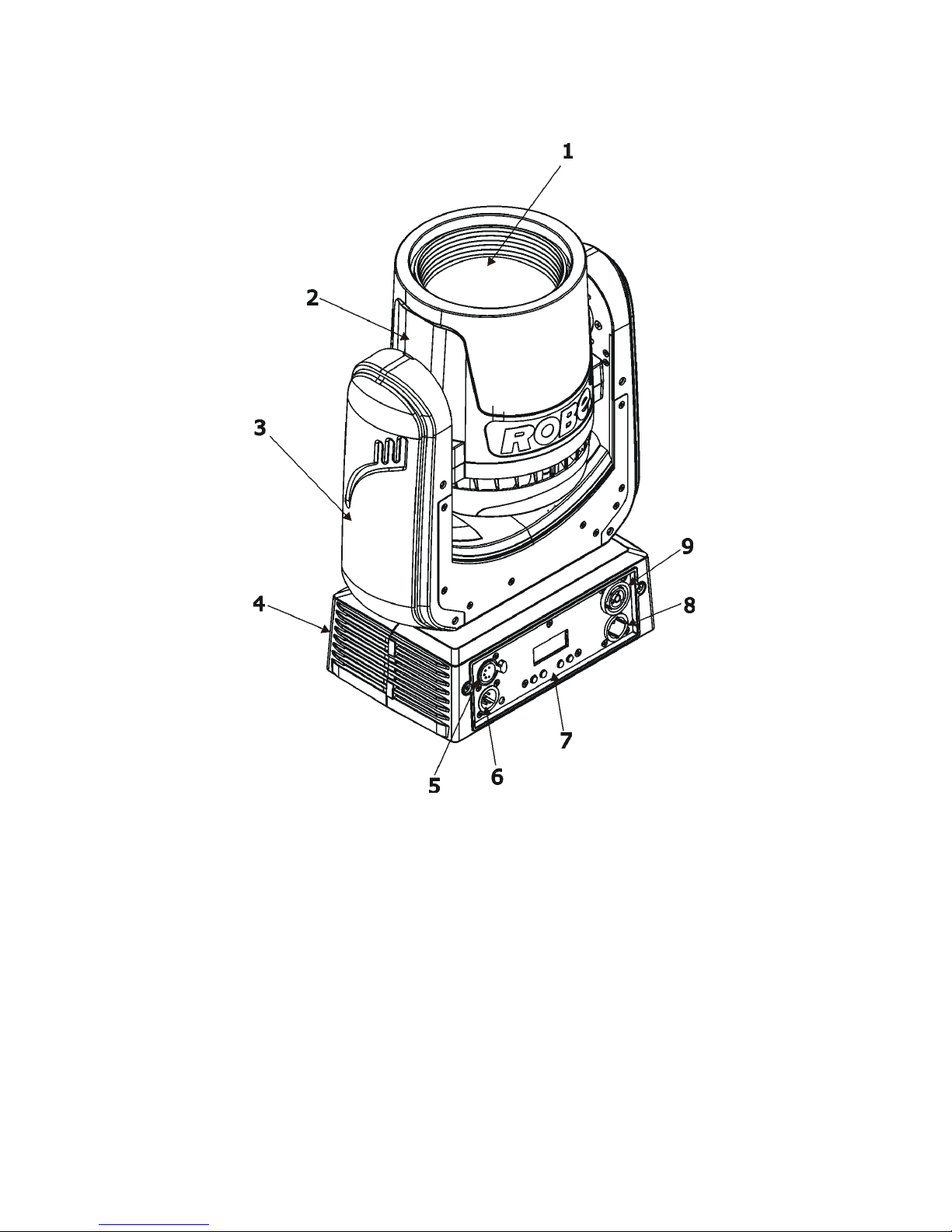
2. Fixture exterior view
1 - Front lens
2 - Moving head
3 - Yoke
4 - Base
5 - DMX Out
6 - DMX In
7 - Control board
8 - Mains In
9 - Mains Out
6
3. Installation
Fixtures must be installed by a Qualied electrician in accordance with all
national and local electrical and construction codes and regulations.
3.1 Connection to the mains
For protection from electric shock, the xture must be earthed!
The Robin Spikie is equipped with auto-switching power supply that automatically adjusts to any 50-60Hz AC
power source from 100-240 Volts.
If you install a cord cap on the power cable to allow connection to power outlets, install a grounding-type (earthed)
plug, following the plug manufacturer’s instructions.
If you have any doubts about proper installation, consult a qualied electrician.
Core (EU) Core (US) Connection Plug Terminal Marking
Brown Black Live L
Light blue White Neutral N
Yellow/Green Green Earth
This device falls under class one and must be earthed (grounded)!
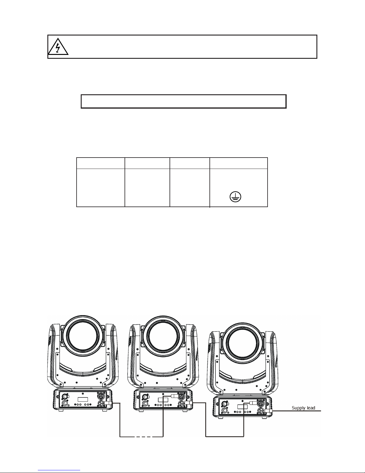
Design of the Robin Spikie allows to connect several xtures to AC mains power in one interconnected daisy
chain using power input and throughput connectors. Needed daisy chain cords are stated in the chapter
“Technical specications “
The max. number of connected xtures depends on the AC mains power voltage and xture version:
EU version (CE) US version (cETLus)
29 xtures at power supply= 230V 17 xtures at power supply= 230V
26 xtures at power supply= 208V 15 xtures at power supply= 208V
15 xtures at power supply= 120V 9 xtures at power supply= 120V
Actual numbers of xtures may differ from values stated above as you have to take into account the length of
supply cables, circuit breaker etc. at projecting of the xtures installation Do not overload the supply line and
the connecting leads.
Wiring and connection work must be carried out by qualied staff!
7
3.2 Rigging the xture
A structure intended for installation of the xture (s) must safely hold weight of the xture(s) placed on it. The
structure has to be certicated to the purpose.
The xture (xtures) must be installed in accordance with national and local electrical and construction codes
and regulations.
For overhead installation, the xture must be always secured with a safety wire that
can bear at least 10 times the weight of the xture.
When rigging, derigging or servicing the xture staying in the area below the installation place, on bridges,
under high working places and other endangered areas is forbidden.
The operator has to make sure that safety-relating and machine-technical installations are approved by a skilled
person once a year.
The xture should be installed outside areas where persons may walk by or be seated.
IMPORTANT! OVERHEAD RIGGING REQUIRES EXTENSIVE EXPERIENCE, including (but not limited to)
calculating working load limits, installation material being used, and periodic safety inspection of all installation
materials and the xture. If you lack these qualications, do not attempt the installation yourself, but instead use
a professional structural rigger. Improper installation can result in bodily injury or damage to property.
The xture has to be installed out of the reach of people.
The xture must never be xed swinging freely in the room.
Caution: Fixture may cause severe injuries when crashing down! If you have doubts concerning the safety of
a possible installation, do not install the moving head!
Before rigging make sure that the installation area can hold a minimum point load of 10 times the xture’s
weight.
When installing the device, make sure there is no highly inammable
material (decoration articles, etc.) in a distance of min. 0.4 m.
CAUTION!
Use an appropriate clamp to rig the xture on the truss.
Make sure that the device is xed properly! Ensure that the
structure (truss) to which you are attaching the xture is secure.
The xture can be placed directly on the stage oor or rigged on a truss without altering its operation characteristics.
Due to very fast pan/tilt movement of the xture, the xture has to be always anchored
to the ground (base) otherwise there is a danger of knocking the xture over.
.
.
8
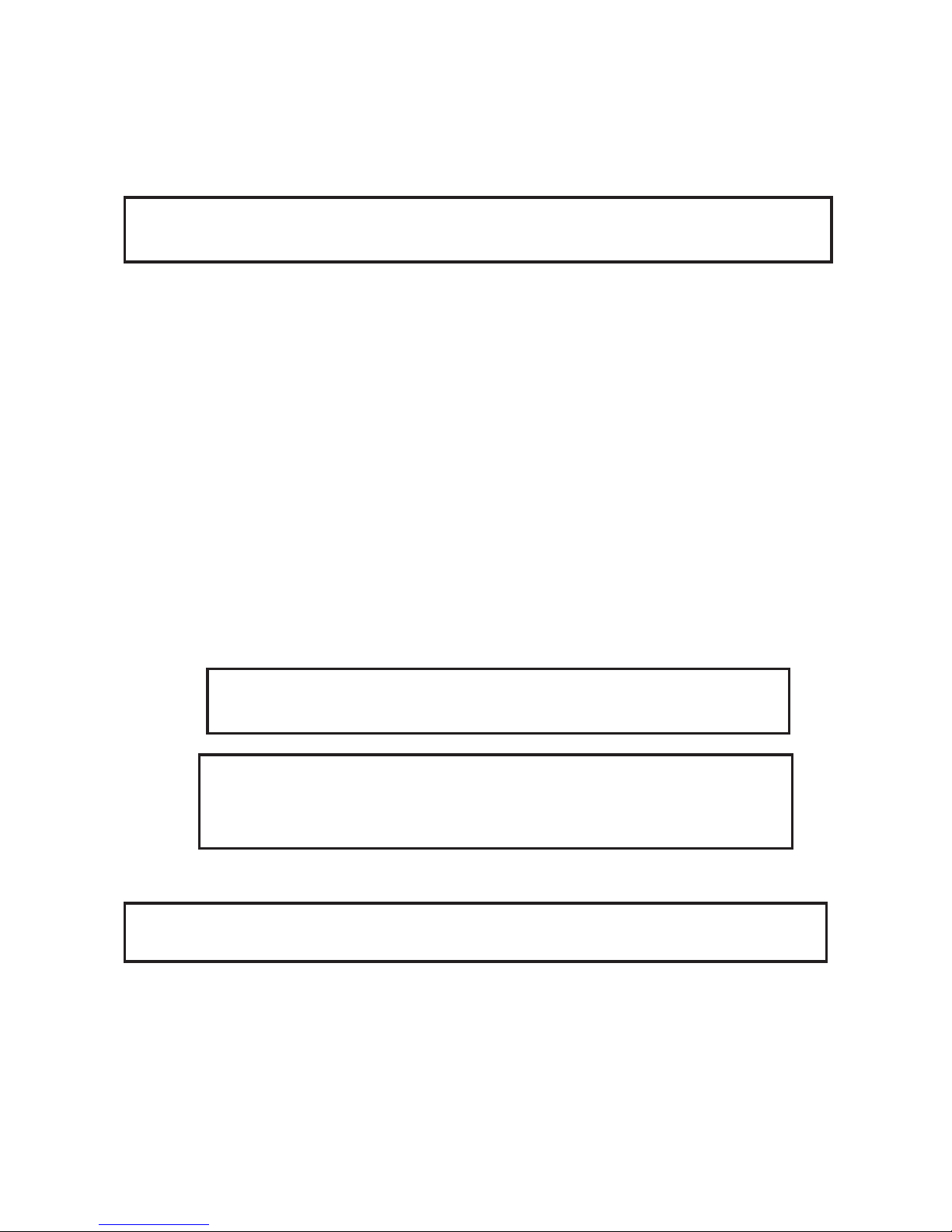
For securing the xture to the truss install a safety wire that can hold at least 10 times the weight of the xture.
Use only the safety wire with a snap hook with screw lock gate. Fasten the snap hook in the attachment point
and the safety wire around the truss as shown on the picture below.
1-Quick-lock fastener
2-Omega holder
3-Trust
4-Clamp
5-Safety wire with a snap hook
with screw lock gate
6-Attachment point
When installing xtures side-by-side, avoid illuminating one xture with
another!

9
3.3 DMX-512 connection
The xture is equipped with 5-pin XLR sockets for DMX input and output. Only use a shielded twisted-pair
cable designed for RS-485 and 5-pin XLR-plugs and connectors in order to connect the controller with the
xture or one xture with another.
DMX output DMX input
XLR socket: XLR plug:
If you are using the standard DMX controllers, you can connect the DMX output of the controller directly with the
DMX input of the rst xture in the DMX-chain. If you wish to connect DMX-controllers with other XLR-outputs,
you need to use adapter-cables.
Building a serial DMX-chain:
Connect the DMX-output of the rst xture in the DMX-chain with the DMX-input of the next xture. Always
connect one output with the input of the next xture until all xtures are connected. Up to 32 xtures can be
interconnected.
Caution: At the last xture, the DMX-cable has to be terminated with a terminator. Solder a 120 Ω resistor
between Signal (–) and Signal (+) into a 5-pin XLR-plug and plug it in the DMX-output of the last xture.
1 - Shield
2 - Signal (-)
3 - Signal (+)
4 - Used for wireless DMX
5 - Used for wireless DMX
1 - Shield
2 - Signal (-)
3 - Signal (+)
4 - Used for wireless DMX
5 - Used for wireless DMX
10
3.4. Wireless DMX operation
The external Robe Wireless CRMX-LB100 module allows receiving wireless DMX. This module is equipped
with the Lumen Radio CRMX module and antenna for receiving DMX signal. CRMX module operates on the
2.4 GHz band.
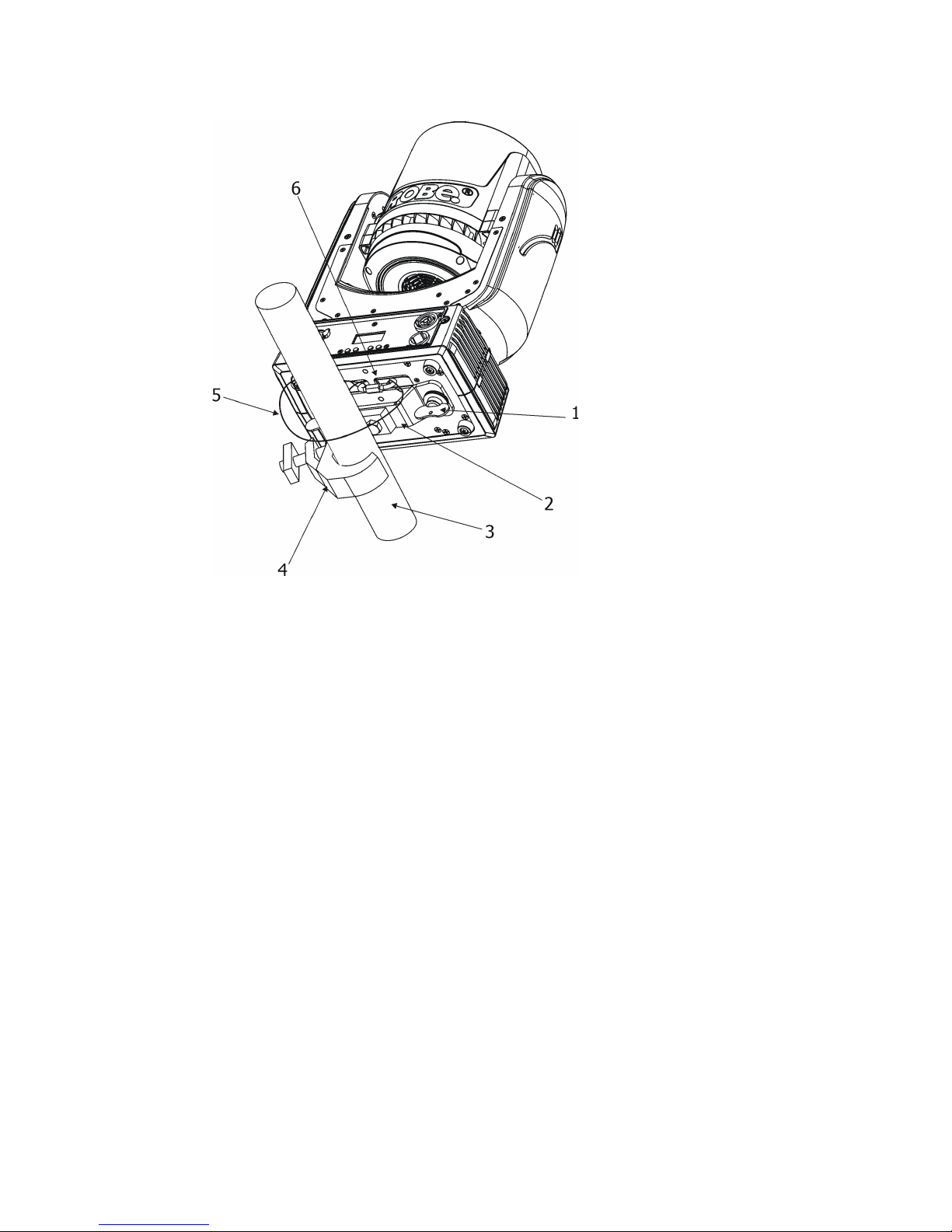
Push in the 5-pin XLR plug (1) into 5-pin XLR sockit (4) and simultaneously locating pin (2) into hole (5) in the
xture. In this way the wireless DMX module is connected with the xture.
NOTE: when you disconnect the DMX wireless module from xture, press and hold lock (5) during getting the
wireless module out.
To link the xture with DMX transmitter.
The xture can be only linked with the transmitter by running the link procedure at DMX transmitter .
After linking , the level of DMX signal ( 0-100 %) is displayed in the menu item “Stat“ (Special -->Vireless ->Stat).
To unlink the xture from DMX transmitter.
The xture can be unlinked from receiver via the menu item “ Unlink“ (Special-->Vireless -->Unlink).
1 - 5-pin XLR (female)
2 - Locating pin
3 - Lock
Robe Wireless CRMX-LB100
11
4. Remotely controllable functions
Virtual Colour wheel
The virtual colour contains 66 preset LEE swatches, rainbow effect in both directions with variable speed.
CTC (colour temperature correction)
The CTC channel allows to change colour temperature of white in range of 2700K-8000K.
Colour Mix control
The Colour Mix control channel denes relation between colour channels (R,G,B,W) and virtual colour wheel:
DMX value Function
0-9 Virtual colour wheel has priority
10-19 Maximum mode (highest values have priority)
20-29 Minimum mode (lowest values have priority)
30-39 Multiply mode (multiply Virtual colour wheel and Colour channels)
40-49 Addition mode (Virtual colour wheel + Colour channels)
50-59 Subtraction mode (Virtual colour wheel – Colour channels)
60-69 Inverted Subtraction mode (Virtual colour wheel – Colour channels)
70-128 reserved
129 Virtual colour wheel has priority
130-254 Cross fade between Virtual colour wheel and colour channels
255 Colour channels have priority
E.g. If you wish to control individual RGBW channels, set the Colour Mix Control channel to 255 DMX, if you
need colours from Virtual colour wheel, set the Colour Mix Control channel to 0 DMX.
Prism
The 3-facet prism rotates in both directions at different speeds.
Flower Effect
The Flower effect rotates in both directions with variable speed. 10 Flower effect macros are created.
Zoom
The motorized zoom module allows beam range of 4°- 27°.
Dimmer/Shutter unit
Smooth 0 - 100 % dimming is provided by the electronic control unit. This unit is also used for strobe effects
with variable speed.
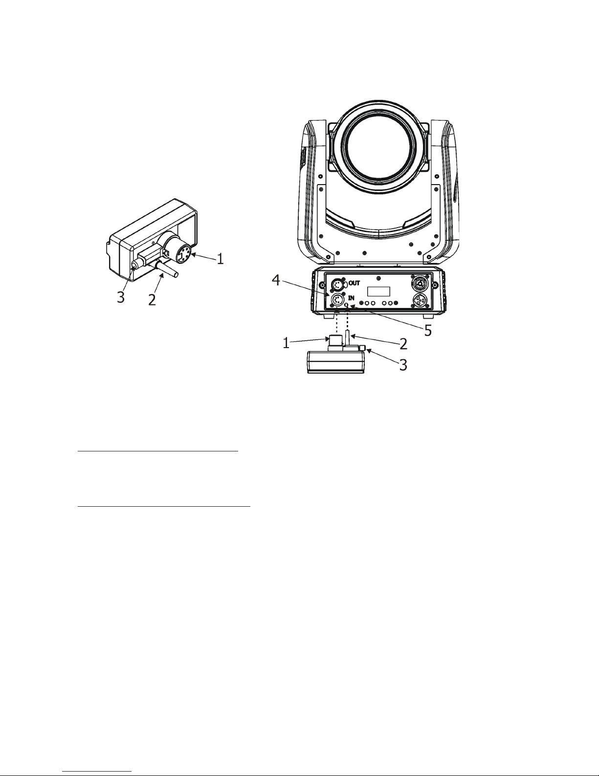
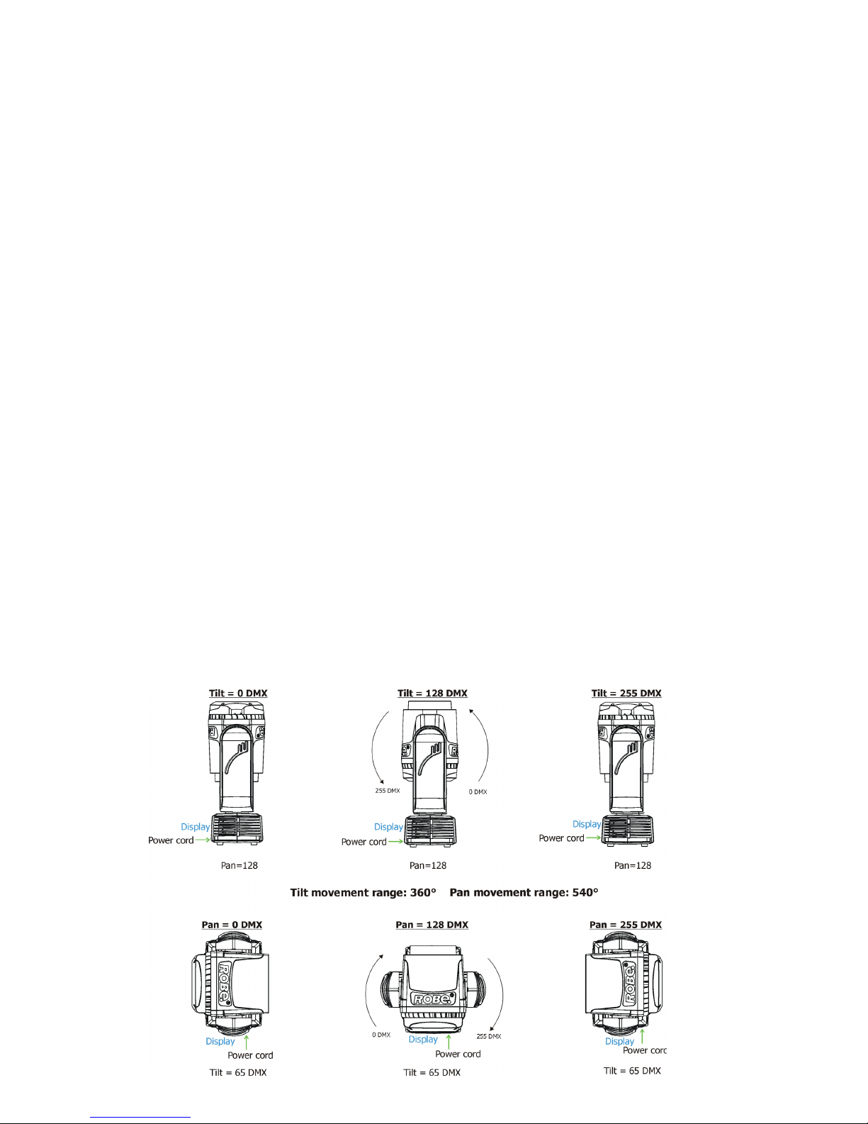
Pan/Tilt
Pan/tilt movement range: 540°/360°, continual pan/tilt rotation.
 Loading...