

Page 1
1
Version 1.3
Page 2

2
Table of contents
1. Safety instructions ......................................................................................................... 3
2. Fixture exterior view ...................................................................................................... 5
3. Installation....................................................................................................................... 6
3.1 Connection to the mains ............................................................................................ 6
3.2 Installing barndoors and the gel frame ....................................................................... 7
3.3 Installing the eggcrate ................................................................................................ 8
3.4 Rigging the xture ...................................................................................................... 9
3.5 DMX-512 connection ................................................................................................ 11
3.6. Wireless DMX operation ......................................................................................... 12
4. Control menu map ........................................................................................................ 13
5. Control menu (Standard and Easy control mode) ..................................................... 15
5.1 Addressing (DMXA) .................................................................................................. 15
5.2 Fixture information (Info) .......................................................................................... 16
5.3 Personality (Pers) ..................................................................................................... 16
5.4 Manual Control (Manual) .......................................................................................... 17
5.5 Test program (Test Prg) ............................................................................................ 17
5.6 Stand-alone (St Alone) ............................................................................................. 17
5.7 Special functions (Special) ....................................................................................... 18
6. RDM ............................................................................................................................... 20
7. Error and information messages ................................................................................ 21
8. Technical Specications .............................................................................................. 21
9. Maintenance and cleaning ........................................................................................... 23
9.1 Replacing the fuse ................................................................................................... 23
9.2 Disposing of the product .......................................................................................... 23
10. Photometric diagrams ............................................................................................... 24
10.1 ROBIN Parfect 150 ................................................................................................ 24
10.2 ROBIN Parfect 150 FW .......................................................................................... 28
11. ChangeLog ................................................................................................................. 30
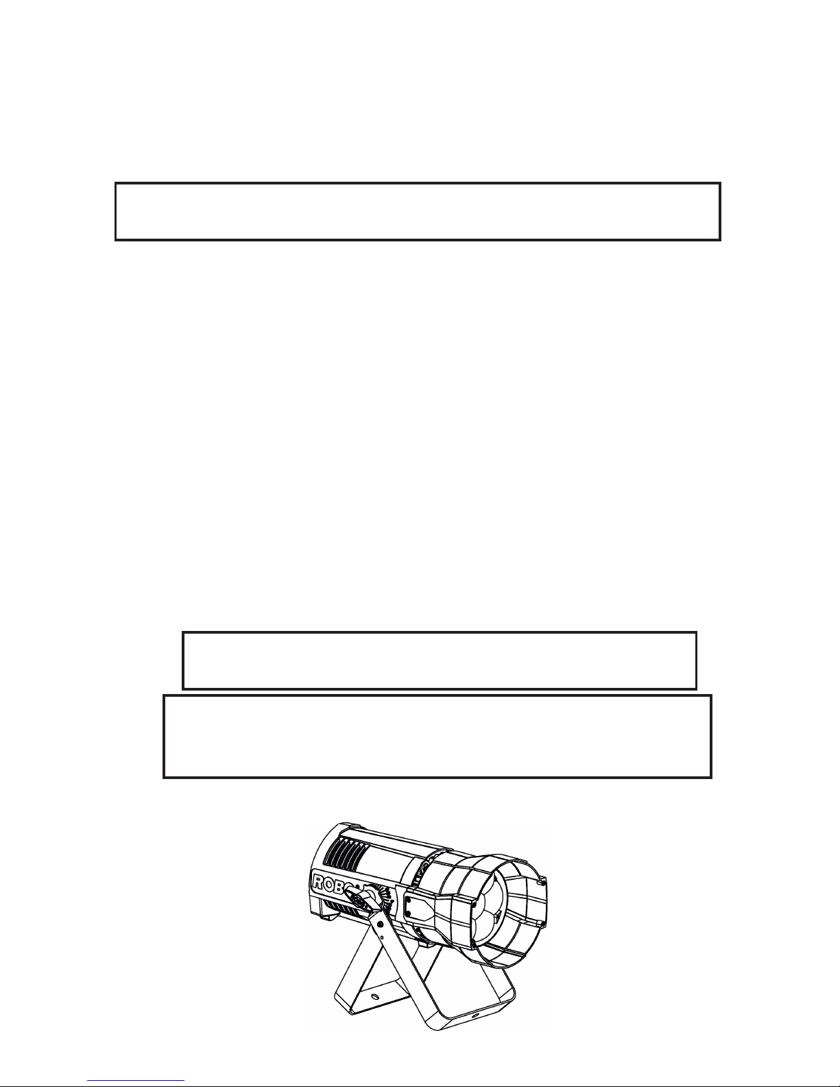
ROBIN ParFect 150
ROBIN ParFect 150 FW
Page 3

3
FOR YOUR OWN SAFETY, PLEASE READ THIS USER MANUAL CAREFULLY
BEFORE POWERING OR INSTALLING YOUR ROBIN ParFect 150 !
Save it for future reference.
This device has left our premises in absolutely perfect condition. In order to maintain this condition and to ensure a safe operation, it is absolutely necessary for the user to follow the safety instructions and warning notes
written in this manual.
The manufacturer will not accept liability for any resulting damages caused by the non-observance of this manual or any unauthorized modication to the device.
Please consider that damages caused by manual modications to the device are not subject to warranty.
The ParFect 150 was designed for indoor use and it is intended for
professional application only. It is not for household use.
1. Safety instructions
DANGEROUS VOLTAGE CONSTITUTING A RISK OF ELECTRIC SHOCK IS PRESENT WITHIN THIS UNIT!
Make sure that the available voltage is not higher than stated on the rear panel of the xture.
This xture should be operated only from the type of power source indicated on the marking label. If you are
not sure of the type of power supplied, consult your authorized distributor or local power company.
Always disconnect the xture from AC power before cleaning, removing or installing any part of the xture.
The power plug has to be accessible after installing the xture. Do not overload wall outlets and extension cords
as this canresult in re or electric shock.
Do not allow anything to rest on the power cord. Do not locate this xture where the cord may be damaged by
persons walking on it.
Make sure that the power cord is never crimped or damaged by sharp edges. Check the xture and the power
cord from time to time.
Refer servicing to qualied service personnel.
This xture falls under protection class I. Therefore this xture has to be connected to
a mains socket outlet with a protective earthing connection.
Do not connect this xture to a dimmer pack.
Warning! Risk Group 2 LED product according to EN 62471.
LED light emission. Risk of eye injury. Do not look into the beam at short distance of
the of the product. Do not view the light output with optical instruments or any device
that may conncentrate the beam.
The light source contains blue LEDs.
If the xture has been exposed to drastic temperature uctuation (e.g. after transportation), do not switch it on
immediately. The arising condensation water might damage your device. Leave the device switched o until
it has reached room temperature.
Avoid brute force when installing or operating the xture.
Page 4

4
This xture was designed for indoor use only, do not expose this unit to rain or use near water.
When choosing the installation spot, please make sure that the xture is not exposed to extreme heat, moisture
or dust.
Do not block the lens array with any object when the xture is under operation.
Openings in housing of the xture should never be covered with cloth or other materials, and never must be
blocked.
This xture should not be placed in a built-in installation unless proper ventilation is provided.
Only operate the xture after having checked that the housing is rmly closed and all screws are tightly fastened.
Make sure that the area below the installation place is blocked when rigging, derigging or servicing the xture.
To avoid damage of an internal optical system of the xture, never let the sunlight (or
other light source) lights directly to the lens array, even when the xture is not working
The xture becomes hot during operation. Allow the xture to cool approximately 15 minutes prior to manipulate
with it.
Operate the xture only after having familiarized with its functions. Do not permit operation by persons not
qualied for operating the xture. Most damages are the result of unprofessional operation!
Please use the original packaging if the xture is to be transported.
Please consider that unauthorized modications on the xture are forbidden due to safety reasons!
If this device will be operated in any way dierent to the one described in this manual, the product may suer
damages and the guarantee becomes void. Furthermore, any other operation may lead to dangers like short-
-circuit, burns, electric shock, crash etc.
Page 5
5
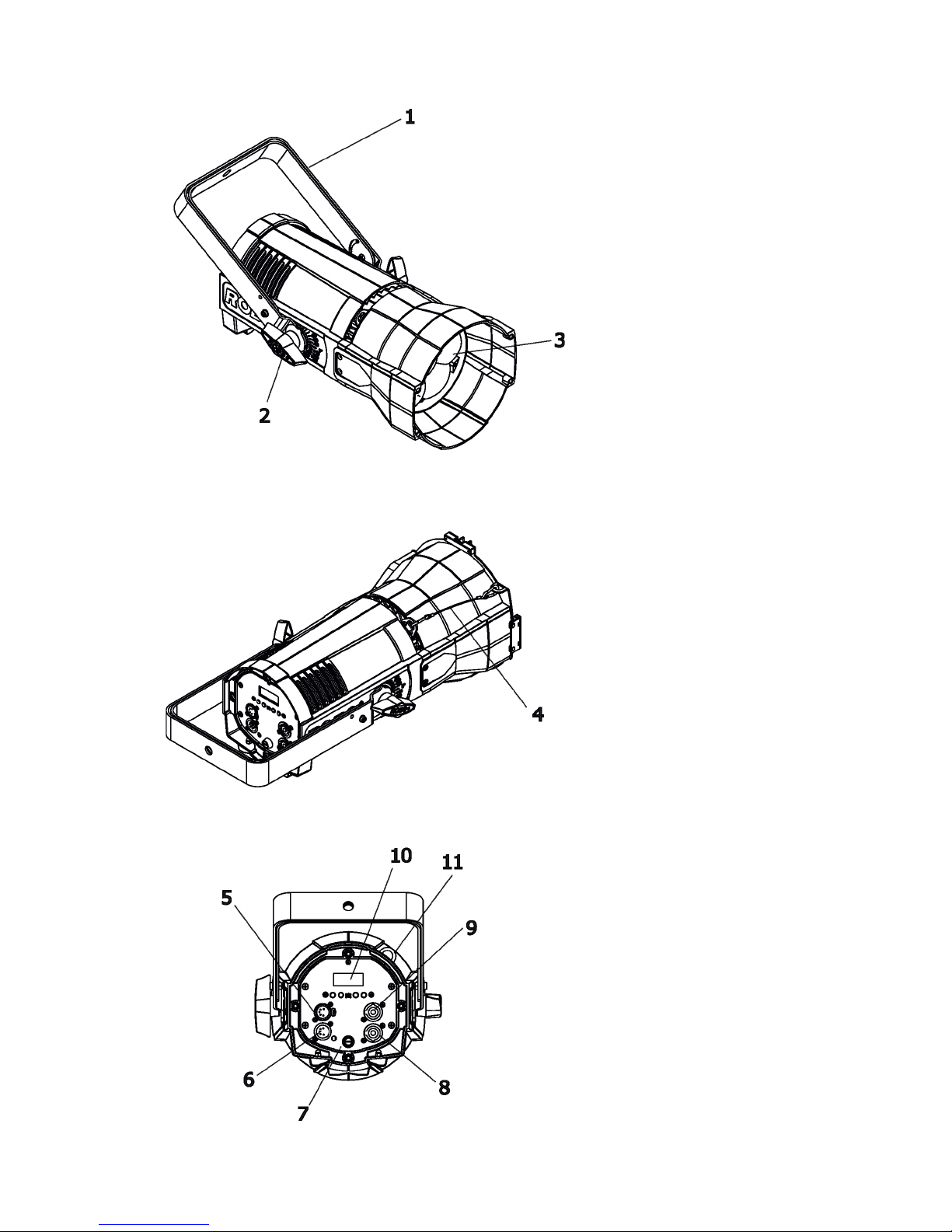
2. Fixture exterior view
4 - Safety wire securing accessory
frame adaptor to the housing
5 - DMX OUT
6 - DMX IN
7 - Fuse holder
8 - Mains IN
9 - Mains OUT
10 - Display and control buttons
11 - Safety wire attachment point
1 - Mounting yoke
2 - Tilt locks
3 - Lenses array
Page 6
6
3. Installation
Fixtures must be installed by a Qualied electrician in accordance with all
national and local electrical and construction codes and regulation.
3.1 Connection to the mains
For protection from electric shock, the xture must be earthed!
The ParFect 150 is equipped with auto-switching power supply that automatically adjusts to any 50-60Hz AC
power source from 100-240 Volts.
If you need to install a cord cap on the power cable to allow connection to power outlet, install a grounding-type
(earthed) plug, following the plug manufacturer’s instructions.
If you have any doubts about proper installation, consult a qualied electrician.
Core (EU) Core (US) Connection Plug Terminal Marking
Brown Black Live L
Light blue White Neutral N
Yellow/Green Green Earth
This device falls under class one and must be earthed (grounded)!
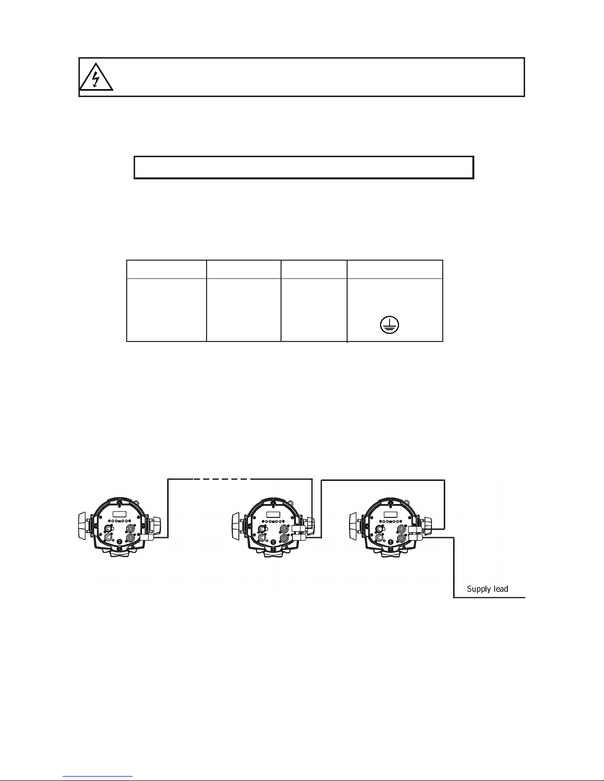
The max. number of connected xtures depends on AC mains power voltage:
CE: ETL:
15 xtures at power supply= 230V 9 xtures at power supply= 230V
13 xtures at power supply= 208V 8 xtures at power supply= 208V
7 xtures at power supply= 120V 4 xtures at power supply= 120V
Actual number of xtures may dier from values stated above as you have to take into account the length of
supply cables, circuit breaker etc. at projecting of the xtures installation Do not overload the supply line and
connecting leads.
Wiring and connection work must be carried out by qualied sta!
.
Page 7
7
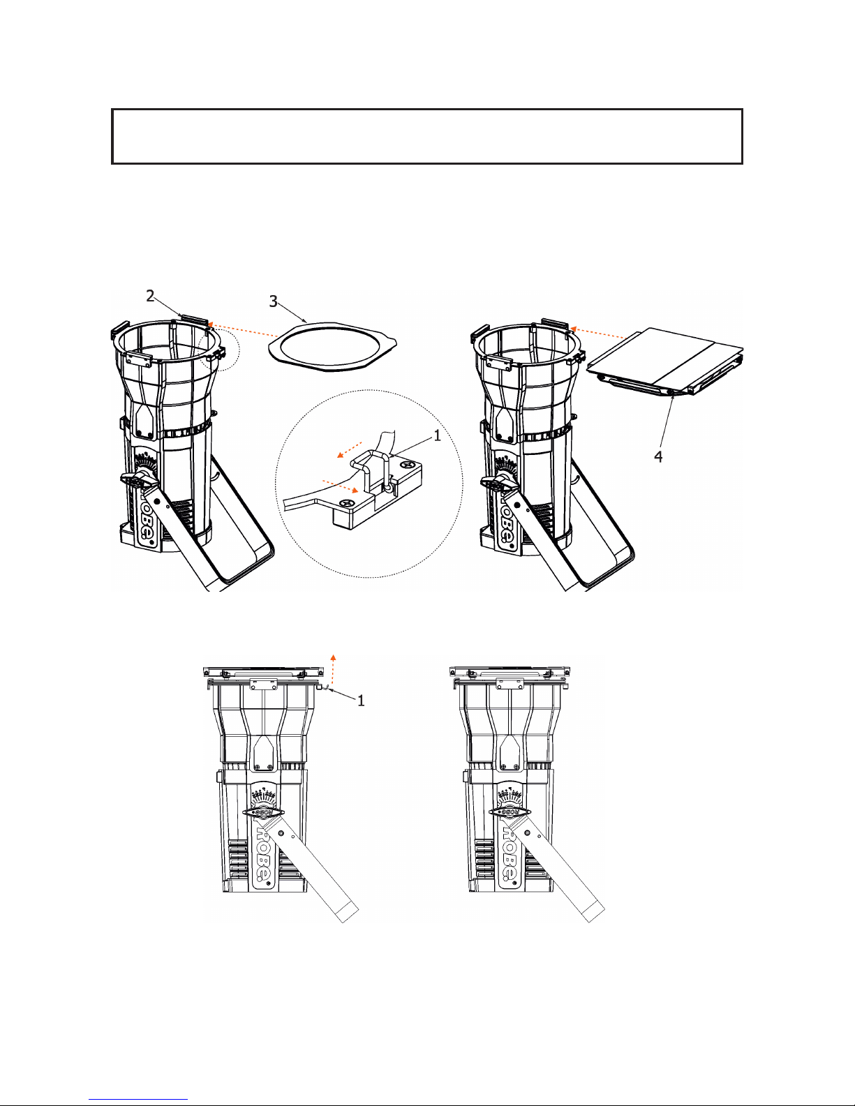
3.2 Installing barndoors and the gel frame
Disconnect the xture from mains before barndoors and the gel frame installation!
DO NOT install the gel frame if the eggcrate has been installed on the xture!
1. Unlock the spring lock (1) of the accessory frame adaptor (2) via pushing this spring lock as show red arrows
on the picture.
2. Insert the gel frame (3) into the bottom slots of the accessory frame adaptor (2).
3. Insert the barndoors (4) into the top slots of the (2).
4. Secure both accessories by moving the spring lock (1) to locked position as shows the red arrow on the picture.
Page 8
8
Note: the barndoors can be rotated to desired position and secured in this position via the securing screw (5).
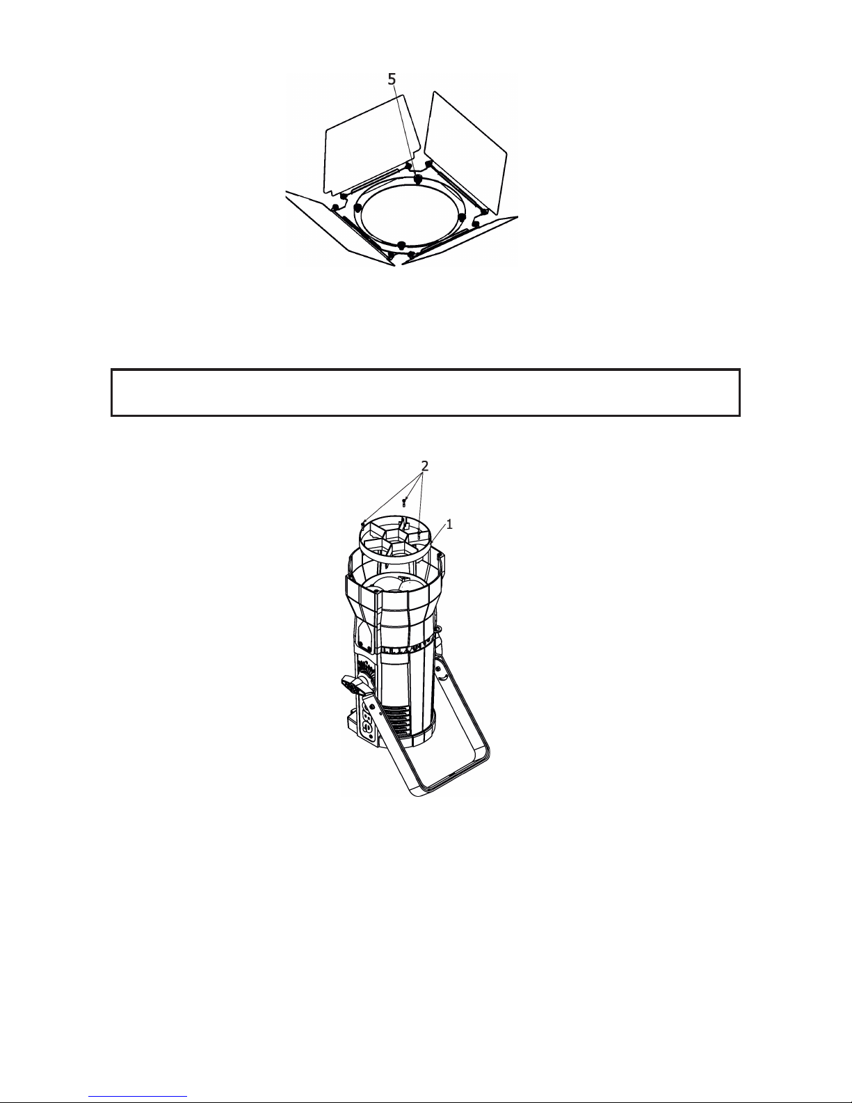
3.3 Installing the eggcrate
Disconnect the xture from mains before eggcrate installation!
DO NOT insert the gel frame after installing the eggcrate on the xture!
Screw the eggcrate (1) on the lens array module via the three screws (2).
Page 9
9
3.4 Rigging the xture
A structure intended for installation of the xture (s) must safely hold weight of the xture(s) placed on it. The
structure has to be certicated to the purpose.
The xture (xtures) must be installed in accordance with national and local electrical and construction codes
and regulation.
For overhead installation, the xture must be always secured with a safety wire.
When rigging, derigging or servicing the xture staying in the area below the installation place, on bridges,
under high working places and other endangered areas is forbidden.
The operator has to make sure that safety-relating and machine-technical installations are approved by an
expert before taking into operation for the rst time and after changes before taking into operation another time.
The operator has to make sure that safety-relating and machine-technical installations are approved by a skilled
person once a year.
Allow the xture to cool for ten minutes before handling.
The projector should be installed outside areas where persons may walk by or be seated.
IMPORTANT! OVERHEAD RIGGING REQUIRES EXTENSIVE EXPERIENCE, including calculating working
load limits, installation material being used, and periodic safety inspection of all installation material and the
projector. If you lack these qualications, do not attempt the installation yourself, but use a help of professional
companies.
CAUTION: Fixtures may cause severe injuries when crashing down! If you have doubts concerning the safety
of a possible installation, do not install the xture!
The xture has to be installed out of the reach of public.
The xture must never be xed swinging freely in the room.
When installing the device, make sure there is no highly inammable
material (decoration articles, etc.) in a distance of min. 0.4 m.
CAUTION!
Use an appropriate clamp to rig the xture on the truss.
Make sure that the device is xed properly! Ensure that the
structure (truss) to which you are attaching the xtures is secure.
The xture can be placed by means of the unfolded mounting yoke on the stage oor or rigged on a truss (with
folded mounting yoke) without altering its operation characte ristics.
.
Page 10
10
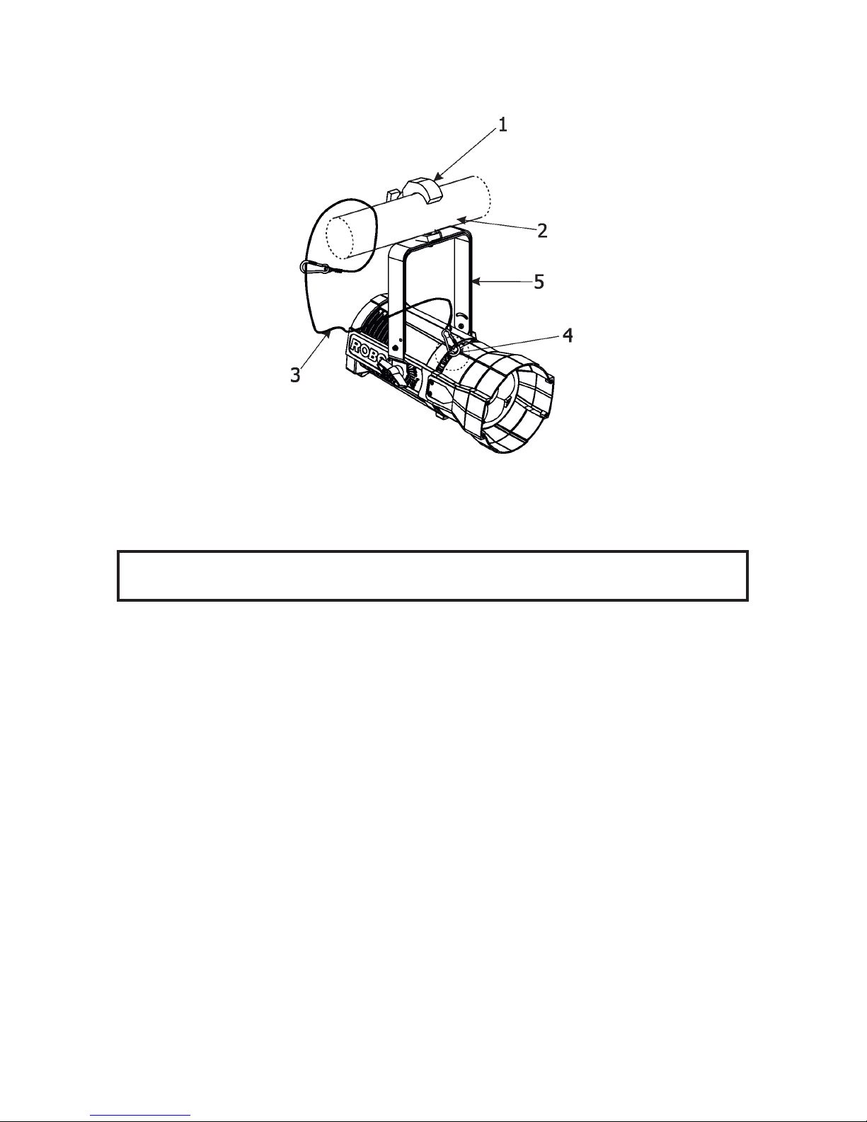
For securing the xture to the truss, install a safety wire which can hold at least 10 times the weight of the xture.
Use only the safety wire with a snap hook with screw lock gate. Fasten the safety cable in the attachment
point and around the truss as shown on the picture below.
When installing xtures side-by-side, avoid illuminating one xture with another!
1-Clamp
2-Truss
3-Safety wire
4-Attachment point
5-Folded mounting yoke
Page 11
11
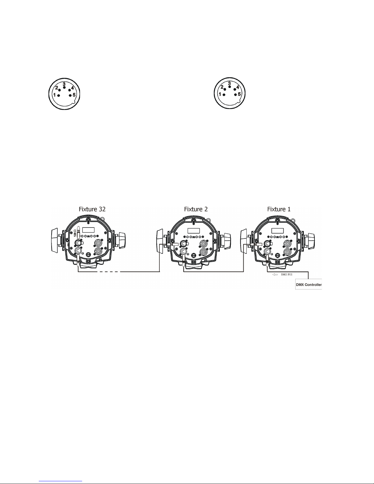
3.5 DMX-512 connection
The xture is equipped with 5-pin XLR sockets for DMX input and output. Only use a shielded twisted-pair
cable designed for RS-485 and 5-pin XLR-plugs and connectors in order to connect the controller with the
xture or one xture with another.
If you are using the standard DMX controllers, you can connect the DMX output of the controller directly with
the DMX input of the rst xture in the DMX-chain. If you wish to connect DMX-controllers with other XLR-outputs, you need to use adapter-cables.
Building a serial DMX-chain:
Connect the DMX-output of the rst xture in the DMX-chain with the DMX-input of the next xture. Always
connect one output with the input of the next xture until all xtures are connected. Up to 32 xtures can be
interconnected.
Caution: At the last xture, the DMX-cable has to be terminated with a terminator. Solder a 120 Ω resistor
between Signal (–) and Signal (+) into a 5-pin XLR-plug and plug it in the DMX-output of the last xture.
DMX output DMX input
XLR socket: XLRplug:
1 - Shield
2 - Signal (-)
3 - Signal (+)
4 - Used for wireless DMX
5 - Used for wireless DMX
1 - Shield
2 - Signal (-)
3 - Signal (+)
4 - Used for wireless DMX
5 - Used for wireless DMX
Page 12

12
3.6. Wireless DMX operation
The external Robe Wireless CRMX-LB100 module allows receiving wireless DMX. This device is equipped
with the Lumen Radio CRMX module and antenna for receiving DMX signal. CRMX module operates on the
2.4 GHz band.
Push the 5-pin XLR plug (1) into 5-pin XLR sockit (4) and at the same time locating pin (2) into the opening (5)
in the xture. In this way the wireless DMX module is connected with the xture.
NOTE: when you disconnecting the DMX wireless module from the xture, press and hold lock (5) during
taking the wireless module out.
To link the xture with DMX transmitter.
The xture can be only linked with the transmitter by running the link procedure at DMX transmitter .
After linking , the level of DMX signal ( 0-100 %) is displayed in the menu item “Stat“ (Special -->Vireless -->Stat).
To unlink the xture from DMX transmitter.
The xture can be unlinked from receiver via the menu item “ Unlink“ (Special-->Vireless -->Unlink.).
1 - 5-pin XLR (female)
2 - Locating pin
3 - Lock
Robe Wireless CRMX-LB100
Page 13

13
4. Control menu map
Default settings=Bold print
Level 1 Level 2 Level 3 Level 4 Level 5 Level 6 Level 7
DMXA Set DMXA 001-512
DMX Pres Mode 1
Mode 2
Info POn Time Total
Reset
DMX In
Powr 0-255
:
Dim F 0-255
Hea Temp Current
Highest
High Res
Sw Ver IC-1
IC-2
Pers
DMX Pres Mode 1
Mode 2
Display Turn
On/O T On, O
Contrast 0-100%
Backlight 0-100%
Mic Sens 0...10...19
Fans Auto, High,Quiet
Col Mix RGBW, CMY
White P On, O
Dimmer C Square, Linear
Temp Uni °C, °F
I Ef Pos Powr
:
Dimm F
Store
Defaults
Manual Manual C Powr 0-255
:
Dim F 0-255
Test Prg
Sta Alone Music T On, O
Auto Run O
Test
Prog 1
:
Prog 3
Pr Play Test Prg
Prog 1
:
Prog 3
Pr Edit Prog 1 Step 1 Powr
Prog 2 : :
Page 14

14
Level 1 Level 2 Level 3 Level 4 Level 5 Level 6 Level 7
Prog 3 Step 40 F.Tim 0-25.5
S.Tim 0-25.5
COPY
Prg En 1-40
Special RDM Low
RDM Hight
Wireless Stat
Unlink
Adjust DMX Val Powr 0-255
:
Dim F 0-255
Clalib Cal Mech Zoom C 0-255
Store
Cal Col Red C 0-255
Gre C 0-255
Blu C 0-255
Whi C 0-255
Store
Cla Load
Sw Upd On, O
Page 15

15
5. Control menu (Standard and Easy control mode)
The ParFect 150 is equipped with 2-row LCD display which allows to set the xture´s behaviour according to
your needs, obtain information on its operation, test its various parts and lastly program it, if it has to be used
in a stand-alone mode.
Control panel
The four control buttons have the following functions:
Standard control mode (default setting)
[ESCAPE] button used to leave the menu without saving changes.
[NEXT] , [PREV] buttons for moving between menu items and for value adjusting.
[ENTER] button used to enter the selected menu (menu item) and to conrm adjusted value.
After switching the xture on, the display shows current DMX address.
Easy control mode
[INTENSITY] buttons used to set light intensity (dimmer).
[COLOR] buttons used to set colour
After switching the xture on, the display shows adjusted dimmer intensity and colour before switching the
Parfect 150 o.
When the xture is switched o, both adjusted color and light intensity are saved into memory to use them
after switching the xture on.
Note: DMX control in this mode is disabled.
Switching the xture to Easy control mode
When the current DMX address is displayed:
press the [NEXT] and [PREV] buttons at the same time until the screen for the Easy control mode appears.
For switching to the Standard control mode, press the [NEXT] and [PREV] buttons at the same time until the
screen for the Standard control mode appears.
The following menu items are accessible in the Standard control mode only.
5.1 Addressing (DMXA)
Set DMXA- Use this menu item to set the DMX start address of the xture, which is dened as the rst channel
from which the ParFect 150 will respond to the controller.
If you set, for example, the address 31, the ParFect 150 will use channels 31 - 48 for control (if Mode 1 is
selected).
Page 16

16
Please, be sure that you do not have any overlapping channels in order to control each ParFect 150 correctly
and independently from any other xture on the DMX data link.
If there is no data received at the DMX input, the display will start to ash "0001” with actually stored DMX address.
DMX Pres - DMX preset. Use the menu to select desired channel mode.
Mode 1 - 17 control channels (default)
Mode 2 - 11 control channels
5.2 Fixture information (Info)
POn Time - Power on time. Select this menu to read the number of xture operation hours.
Total -
The item shows the total number of the operation hours since
the ParFect 150
has been fabricated.
Reset -
The item shows the number of the operation hours that the
ParFect 150
has been powered on since the counter was last reset.
In order to reset this counter to 0, press and hold both [NEXT] and [PREV] buttons and the
[Enter] button at the same time.
DMX In - DMX readout. The menu is used to read DMX values of each channel received by the xture.
Hea. Temp - Temperature. The menu shows temperature of the LED module.
Current - A current temperature of the LED module.
Highest - A maximum temperature of the the LED module since the xture has
been fabricated.
High Res - A maximum temperature of the the LED module since the counter
was last reset.
In order to reset this counter, press and hold both [NEXT] and [PREV] buttons and the
[Enter] button at the same time.
Sw Ver - Software versions. Select this item to read the software version of the xture modules.
IC-1 - A display processor.
IC-2 - A LED control processor.
5.3 Personality (Pers)
DMX Pres - DMX preset. Use the menu to select desired channel mode.
Mode 1 - 17 control channels (default)
Mode 2 - 11 control channels
Display - Display adjusting. This menu allows you to adjust the display behaviour.
Turn - This function turns the display by 180°.
On/O T - This function allows you to keep the display permanent on or turn it o two
minutes after last pressing any button on the control panel.
Contrast- Use this function to adjust contrast of the display (0-100%).
Backlight- Use this function to adjust backlight of the display (0-100%).
Col. Mix. - Colour mixing mode. This item allows switching into RGBW or CMY mode. In the CMY mode, the
white(8bit) and white (16) bit channels are not active.
White P - White Point 8000K. If the function is on, the CTC channel allows to set desired white in range of
8000K-2700K
(0 DMX=8000K,64 DMX=5600K, 128 DMX=4200K, 192 DMX=3200K, 255 DMX=2700K). Necessary condition
is , that RGBW channels have to be full or set at the same DMX values, e.g. 255.
If this function is o, the range of whites is not uniform and may be dierent for each xture.
Mic Sens - Microfon sensitivity. Enter the menu if you want to adjust the microphone sensitivity (0-min., 19max.).
Fan - Fan mode. Use the menu to set the xture fan to the max. power ("High") ,auto-control mode ("Auto")
and quiet mode ("Quiet"). In the quiet mode is a speed of zoom reduced.
Page 17

17
Temp Uni - Temperature unit. Use the menu item to change temperature unit from °C to °F.
I Ef Pos - Init eect positions. Use the menu to set all eects to the desired positions at which they will stay
after switching the xture on without DMX signal connected.
Defaults - The menu item allows to set all xture parameters to the default (factory) values.
5.4 Manual Control (Manual)
Use the menu to control all xture channels by means of the control panel.
5.5 Test program (Test Prg)
Use this menu to to run a special demo-test sequences without an external controller, which will show you some
possibilities of using the ParFect 150.
5.6 Stand-alone (St Alone)
The ParFect 150 oers three user-editable programs (Prog 1-Prog 3), each up to 40 steps. T
Music T - Music trigger. Select this function to enable the sound control of the running program via the built-in
microphone.
Auto Run - Presetting playback. This function allows you to select the program which will be played in
the stand-alone mode after switching the xture on. Selected program will be played continuously in a loop.
O - The option disables „Auto Run” function.
Test, Prog 1, Prog 2, Prog 3 - Selected program will start running after switching
the xture on.
Pr Play - Playing program. Select this menu to run a desired program in a loop (Test Prg, Prog 1-Prog 3).
Select the program you wish to run and press the [ENTER]. The selected program
will start running. By Pressing the [ENTER] again, the program pauses running.
Pr Edit - Editing program. Select this menu to edit or create three editable programs (Prog 1-Prog 3). Each
program step has a step time - during which eects last in the current step and a fade time- during which eects
move to new positions.
To edit program.
1. Press [NEXT] or [PREV] to select the menu "Pr Edit" and press [ENTER].
2. Press [NEXT] or [PREV] to select the desired program and press [ENTER] button.
3. Press [NEXT] or [PREV] to select the desired program step and press [ENTER] button.
4. Press [NEXT] or [PREV] to select the desired item and press [ENTER] button. Now you can edit by [NEXT]
or [PREV] buttons the DMX value (0-255) for selected item:
Prg En.
a total number of the program steps (value 1-40). This value you should be set before
starting of programming
(e.g. if you want to create program with the 10 steps,
set Prg En=10).
Powr power/special functions
Virt C a virtual colour wheel
Red a red colour coarse
Red F a red colour ne
Green a green colour coarse
Green F a green colour ne
Blue a blue colour coarse
Blue F a blue colour ne
White a white colour
White F a white colour ne
CTC a colour temperature correction
C Mix C a colour mix control
Zoom a zoom function
Zoom F a zoom function ne
Stro a strobe/shutter function
Page 18

18
Dimm a dimmer function coarse
Dim F a dimmer function ne
F.Tim a fade time (0-25.5 sec)
S.TiM a step time (0-25.5 sec)
COPY copying the current prog. step to
the next prog. step
5. Press [ENTER] button to conrm adjusted value .
6. Press [ESCAPE] button, select next prog. step, press [ENTER] button and repeat steps 4 - 5).
5.7 Special functions (Special)
RDM Low - This menu item shows the rst part of the RDM identication code.
RDM High - This menu item shows the second part of the RDM identication code.
Wireless - Wireless DMX information. The menu allows to read some information about
Wireless DMX operation
Stat - Wireless status. Use the menu to read wireless DMX status.
Unlink - use this item to unlink xture from wireless DMX.
Adjust - Adjustment. The menu allows the ne adjustment of eects.
DMX Val- DMX values. Use the menu to set DMX values of xture´s channels.
Calib - calibration of white colour.
Cal Mech - Use this menu to calibrate a zoom position.
Cal Col - Use this menu to set white colour 5600K.
Calibration of the zoom position via the control board
1. Disconnect DMX controller from the xture and enter the "Cal Mech" menu.
2. Use the [PREV] and [NEXT] to nd "Zoom C" and press [ENTER].
3. Set desired value and conrm it by pressing [ENTER]..
4. After calibration, nd item "Store" and press [ENTER]. to save all adjusted values and reset the xture.
Calibration of the white 5600K via the control board
1. Disconnect DMX controller from the xture , set the shutter, dimmer and RGBW channels at 255 DMX, zoom
at 128 DMX and the CTC channel at DMX=64 (white 5600K). Aim the light beam on the lux meter (e.g. Minolta
CL-500 A Chroma meter) which is placed cca 5m from the xture.
2. Set the menu items Colour Mix Mode to RGBW and "White Point 8000K to On (Pers-> C Mix M -> RGBW,
Pers-> White P -> On).
3. Enter the menu "Cal Col".
4. By means of the "Red C, Gre C, Blu C and Whi C" items adjust the 5600K colour temperature
as exactly as possible (∆u´v´= 0).
5. After adjusting 5600K colour temperature, select item Store and press the [ENTER] button to save all
adjusted values .
Note: you can also use DMX controler for both calibrations stated above, calibration protocol is the following:
Eect Mode 1 Mode 2
Zoom -ne adjustment channel 18 channel 12
Red - red saturation channel 19 channel 13
Green- green saturation channel 20 channel 14
Blue - blue saturation channel 21 channel 15
White - white saturation channel 22 channel 16
Cal Load - Loads default (factory) calibration.
Sw Upd - Software update. The menu item allows you to update software in the xture via either serial or
USB port of PC.
The following are required in order to update software:
- PC running Windows XP/7/8/10 or Linux
- Update software
- Flash cable RS232/DMX P/N.13050624 (if you want to use a serial port of PC)
- Robe Universal Interface (if you want to use an USB port of PC)
Page 19

19
Note 1: Software update should perform a qualied person. If you lack qualication, do not attempt the update
yourself and ask for help your ROBE distributor.
Note 2: DMX address, , programs 1-3 and all items in the menu "Pers" will be set to their default (factory) values
after software update.
To update software in the xture:
I. Installation of the update software.
1. Update Software available from the ROBE web site at WWW.robe.cz.
2. Make a new directory ( e.g. Robe_Uploader) on your hard disk and download the software to it.
3. Unpack the program to the directory.
II.Fixture software updating.
1.Determine which of your ports is available on your PC and connect it:
- with the DMX input of the xture if you using the ash cable RS232/DMX
- with the USB input of the Robe Universal Interface if you using the USB cable. Connect DMX
output of the Robe Universal Interface with the xture via a standard DMX cabel.
Turn both the computer and the xture on. Make sure the lamp is switched o (only if the xture
has a lamp).
2. Switch the xture to the updating mode (Special -> "SW Upd "-> On).
Note: If you do not want to continue in software update, you have to switch o and on the xture
to escape from this menu.
We recommend to cancel all running programs on PC before starting the software update.
3. Run the Software Uploader. Select desired COM and then click on the Connect button.
(Select COM if the serial port is used or Robe Universal Interface if the USB port is used).
If the connection is OK, click on the “Start Uploading button“ to start uploading. It will take several
minutes to perform software update.
If the option "Incremental Update" is not checked, all processors will be updated (including
processors with the same software version).
If you wish to update only later versions of processors, check the “Incremental Update box“.
Avoid interrupting the process. Update status is being displayed in the Info Box window.
When the update is nished, the line with the text “The xture is successfully updated“ will appear in
this window and the xture will reset with the new software.
Note: In case upload process is interrupted (e.g. power loss), the xture stays in “Updating mode” and you will
have to repeat the software update again.
Page 20

20
6. RDM
This xture supports RDM operation. RDM (Remote Device Management) is a bi-directional communications
protocol for use in DMX512 control systems, it is the new open standard for DMX512 device conguration and
status monitoring.
The RDM protocol allows data packets to be inserted into a DMX512 data stream without adversely aecting
existing non-RDM equipment. By using a special „Start Code,“ and by complying with the timing specications
for DMX512, the RDM protocol allows a console or dedicated RDM controller to send commands to and receive
messages from specic moving lights.
RDM allows explicit commands to be sent to a device and responses to be received from it.
The list of commands for the ParFect 150 is the following.
Parameter ID Discovery command SET command GET command
DISC_UNIQUE_BRANCH *
DISC_MUTE *
DISC_UN_MUTE *
DEVICE_INFO *
SUPPORTED_PARAMETERS *
SOFTWARE_VERSION_LABEL *
DMX_START_ADDRESS * *
IDENTIFY_DEVICE * *
DEVICE_MODEL_DESCRIPTION *
MANUFACTURER_LABEL *
DEVICE_LABEL * *
SENSOR_DEFINITION *
SENSOR_VALUE *
DISPLAY_INVERT * *
DISPLAY_LEVEL * *
DEVICE_RESET *
DMX_PERSONALITY * *
DMX_PERSONALITY_DESCRIPTION *
STATUS_MESSAGES *
STATUS_ID_DESCRIPTION *
DEVICE_HOURS
*
PARAMETER_DESCRIPTION *
ROBE_DMX_INPUT * *
ROBE_WIRELESS_UNLINK *
Page 21

21
7. Error and information messages
Short Err
The message informs you that short circuit has occured on the LED PCB.
8. Technical Specications
Electrical
Power supply:.........................electronic auto-ranging
Input voltage range:............... 100-240V, 50-60Hz
Fuse:.......................................T 3.15A
Max. power consumption .....220W (I=1A, power factor=0.96 at 230V)
Mains input: CE - max. 16A
ETL - max. 10A
Mains output: CE - max. 15A
ETL - max. 9A
Optic
Light source: 7 x 30W RGBW multichip LEDs
Min LED life expectancy: 20.000 hours
RGBW/CMY colour mixing
Variable CTO 2700-8000K
Virtual colour wheel
66 preset colours
Halogen lamp eect at whites 2700K and 3200K
Rainbow eect with in both directions with variable speed
Zoom range
Parfect 150: 3.8°-60°
Parfect 150FW: 3.8°-60°
Strobe
Strobe eect with variable speed (0.3 - 20Hz)
Random strobe pulse-eect with variable speed
Opening/closing pulse eect with variable speed
Dimmer
Smooth dimmer from 0 - 100 %
Control
2-row LCD display & 4 buttons
Readout xture usage, receiving DMX values, temperatures, etc
Built-in analyzer for easy fault nding, error messages
Built-in demo sequences
Quiet fan cooling
Stand-alone operation
3 user editable programs, each up to 40 steps
Supported protocols: USITT DMX 512, RDM,
Support of RDM (Remote Device Management)
2 DMX modes (17, 11 control channels)
2 control modes (Standard and Easy)
External Wireless DMX/RDM module (option)
Compliance with USITT DMX-512 (1986 & 1990) and 512-A
Full DMX delity and frame integrity
Auto sensing of DMX frame rate and frame size
Page 22

22
<5ms DMX latency
Operational frequency range of 2402-2480 MHz
Producer: LumenRadio
Connection
DMX data in/out: Locking 5-pin XLR
AC power input: Chassis connector Neutrik PowerCon, A-type, NAC3MPA
AC power output: Chassis connector Neutrik PowerCon, B-type, NAC3MPB
Note: mains cable is optional accessories
Rigging
Mounting horizontally or vertically via mounting yoke (305° tilt range)
Temperatures
Maximum ambient temperature : 40° C
Maximum surface temperature : 80° C (at LEDs heat sink)
Distances
Min. distance from ammable surfaces: 0.4 m
Min. distance of illuminated objects: 0.8 m
Total heat dissipation
750 BTU/h (calculated)
Weight
5 kg
Dimensions (mm)
Wireles DMX module: Robe Wireless CRMX-LB100
Page 23

23
Included items
ROBIN Parfect 150: 1 x ROBIN Parfect 150
1 x Accessory frame adaptor for Parfect 150 (P/N 99015324)
(installed on the xture)
1 x User manual
ROBIN Parfect 150 FW: 1 x ROBIN Parfect 150 FW
1 x Accessory frame adaptor for Parfect 150 (P/N 99015324)
(installed on the xture)
1 x User manual
Optional accessories
(P/N 10980127) Robe Wireless CRMX-LB100
(P/N 10980346) EggCrate for Robin LEDBeam 150
(P/N 10980348) HALO Frame adaptor for Robin ParFect 150
(P/N 10980349 Barndoor for Robin ParFect 150
(P/N 10980372) Gel Frame for Parfect 150
(P/N 10980373) Diusion lter 2°
(P/N1305 1731) Mains Cable PowerCon In/open ended, 2m
(P/N 1305 1724) Mains Cable PowerCon In/Schuko, 2m
(P/N 1305 1725) Mains Cable PowerCon In/CEE 16A, 2m
(P/N 1305 1726) Mains Cable PowerCon In/US, 2m
(P/N 1305 1727) Daisy Chain PowerCon In/Out, EU, 2m
(P/N 1305 1728 ) Daisy Chain PowerCon In/Out, US, 2m
9. Maintenance and cleaning
DANGER !
Disconnect from the mains before starting any
maintenance work
A soft lint-free cloth moistened with any good glass cleaning uid is recommended, under no circumstances
should solvents be used!
Never use solvents for cleaning lenses in the moving head!
It is absolutely essential that the xture is kept clean and that dust, dirt and smoke-uid residues must not build
up on or within the xture. Otherwise, the xture‘s light-output will be signicantly reduced. Regular cleaning will
not only ensure the maximum light-output, but will also allow the xture to function reliably throughout its life.
Lenses may require monthly cleaning as smoke-uid tends to building up residues, reducing the light output
very quickly. The cooling fans should be cleaned according to the situation (at least annually).
The interior of the base should be cleaned at least annually using a vacuum-cleaner or an air-jet.
More complicated maintenance and service operations are only to be carried out by authorized distributors.
9.1 Replacing the fuse
Replace the fuse by a fuse of the same type and rating only.
Before replacing the fuse, unplug mains lead!
1) Remove the fuse holder on the rear panel of the base with a tting screwdriver from the housing (anti-clockwise).
2) Remove the old fuse from the fuse holder.
3) Install the new fuse in the fuse holder (only the same type and rating).
4) Replace the fuseholder in the housing and x it.
9.2 Disposing of the product
To preserve the environment please dispose or recycle this product at the end of its life according to the local
regulations and codes.
Page 24

24
10. Photometric diagrams
10.1 ROBIN Parfect 150
Page 25

25
Page 26

26
Page 27

27
Page 28

28
10.2 ROBIN Parfect 150 FW
Page 29

29
Copyright © 2017 Robe Lighting - All rights reserved
Specications are subject to change without notice.
October 30, 2017
Made in ROBE Lighting s.r.o., Palackého 416, 757 01 Valašské Meziříčí, Czech Republic
Page 30

30
11. ChangeLog
This section summarizes all types of changes in the user manual.
Version of the
manual
Date of issue Description of changes
1.1 14/05/2017 EggCrate installation added, DMX protocol ver.1.1
1.2 07/06/2017 Quiet mode for fan in menu Personality, DMX protocol ver. 1.2
1.3 30/10/2017 Accessory frame safety wire added
Page 31

DMX protocol
1
2
1 1
Power/Special functions
0 -19 Reserved (0=default)
To activate following functions, stop in DMX value for at least 3 s
and shutter must be closed at least 3 sec. („Shutter,Strobe”
channel 20/15 must be at range: 0-31 DMX). Corresponding menu
items are temporarily overriden.
20-24
Display ON
step
25-29
Display OFF
step
30-34
RGBW colour mixing mode
step
35-39
CMY colour mixing mode
step
40-59 Reserved
60 - 64 Dimmer curve - square law step
65 - 69 Dimmer curve - linear step
70 - 74
Fan mode: Auto
step
75 - 79
Fan mode: High
step
80-84
White point 8000K ON
step
85-89
White point 8000K OFF
step
90-94
Fan mode: Quiet
step
95 -129
Reserved
To activate following functions, stop in DMX value for at least 3
seconds.
130 - 149 Reserved
150 - 159 Zoom reset step
160 - 169 Reserved
Tungsten effect simulution for whites 2700K and 3200K
170-171 Tungsten effect simulation (750W) On step
172-173 Tungsten effect simulation (1000W) On step
174-175 Tungsten effect simulation (1200W) On step
176-177 Tungsten effect simulation (2000W) On step
178-179 Tungsten effect simulation (2500W) On step
180-181 Tungsten effect simulation Off step
182-255 Reserved
2 2
Virtual colour wheel
0 No function (0=default) step
1-2
Filter 4 (Medium Bastard Amber)
step
3-4
Filter 25 (Sunset Red)
step
5-6
Filter 19 (Fire)
step
7-8
Filter 26 (Bright Red)
step
9-10
Filter 58 (Lavender)
step
11-12
Filter 68 (Sky Blue)
step
13-14
Filter 36 (Medium Pink)
step
15-16
Filter 89 (Moss Green)
step
17-18
Filter 88 (Lime Green)
step
19-20
Filter 90 (Dark Yellow Green)
step
21-22
Filter 49 (Medium Purple)
step
23-24
Filter 52 (Light Lavender)
step
25-26
Filter 102 (Light Amber)
step
Robin Parfect 150/Robin Parfect 150FW - DMX protocol
Version: 1.2 Mode 1-Standard 16-bit, Mode 2 -Reduced 8-bit
Mode/channel
DMX
Value
Function
Type of
control
Page 1
Page 32

DMX protocol
1
2
Mode/channel
DMX
Value
Function
Type of
control
27-28
Filter 103 (Straw)
step
29-30
Filter 140 (Summer Blue)
step
31-32
Filter 124 (Dark Green)
step
33-34
Filter 106 (Primary Red)
step
35-36
Filter 111 (Dark Pink)
step
37-38
Filter 115 (Peacock Blue)
step
39-40
Filter 126 (Mauve)
step
41-42
Filter 117 (Steel Blue)
step
43-44
Filter 118 (Light Blue)
step
45-46
Filter 122 (Fern Green)
step
47-48
Filter 182 (Light Red)
step
49-50
Filter 121 (Filter Green)
step
51-52
Filter 128 (Bright Pink)
step
53-54
Filter 131 (Marine Blue)
step
55-56
Filter 132 (Medium Blue)
step
57-58
Filter 134 (Golden Amber)
step
59-60
Filter 135 (Deep Golden Amber)
step
61-62
Filter 136 (Pale Lavender)
step
63-64
Filter 137 (Special Lavender)
step
65-66
Filter 138 (Pale Green)
step
67-68
Filter 798 (Chrysalis Pink)
step
69-70
Filter 141 (Bright Blue)
step
71-72
Filter 147 (Apricot)
step
73-74
Filter 148 (Bright Rose)
step
75-76
Filter 152 (Pale Gold)
step
77-78
Filter 154 (Pale Rose)
step
79-80
Filter 157 (Pink)
step
81-82
Filter 143 (Pale Navy Blue)
step
83-84
Filter 162 (Bastard Amber)
step
85-86
Filter 164 (Flame Red)
step
87-88
Filter 165 (Daylight Blue)
step
89-90
Filter 169 (Lilac Tint)
step
91-92
Filter 170 (Deep Lavender)
step
93-94
Filter 172 (Lagoon Blue)
step
95-96
Filter 194 (Surprise Pink)
step
97-98
Filter 180 (Dark Lavender)
step
99-100
Filter 181 (Congo Blue)
step
101-102
Filter 197 (Alice Blue)
step
103-104
Filter 201 (Full C.T. Blue)
step
105-106
Filter 202 (Half C.T. Blue)
step
107-108
Filter 203 (Quarter C.T. Blue)
step
109-110
Filter 204 (Full C.T. Orange)
step
111-112
Filter 219 (Fluorescent Green)
step
113-114
Filter 206 (Quarter C.T. Orange)
step
115-116
Filter 247 (Filter Minus Green)
step
117-118
Filter 248 (Half Minus Green)
step
119-120
Filter 281 (Three Quarter C.T. Blue)
step
121-122
Filter 285 (Three Quarter C.T. Orange)
step
123-124
Filter 352 (Glacier Blue)
step
Page 2
Page 33

DMX protocol
1
2
Mode/channel
DMX
Value
Function
Type of
control
125-126
Filter 353 (Lighter Blue)
step
127-128
Filter 507 (Madge)
step
129-130
Filter 778 (Millennium Gold)
step
131-132
Filter 793 (Vanity Fair)
step
133-235 Raw DMX proportional
236-245 Rainbow effect (with fade time) from slow-> fast proportional
246-255 Rainbow effect (without fade time) from slow-> fast proportional
3 3
Red/Cyan (8 bit)*
0 - 255 Colour saturation control - coarse 0-100% (255=default) proportional
4 *
Red/Cyan (16bit)*
0 - 255 Colour saturation control - fine (255=default) proportional
5 4
Green/Magenta (8 bit) *
0 - 255 Colour saturation control - coarse 0-100% (255=default) proportional
6 *
Green/Magenta (16bit) *
0 - 255 Colour saturation control - fine (255=default) proportional
7 5
Blue/Yellow (8 bit) *
0 - 255 Colour saturation control - coarse 0-100% (255=default) proportional
8 *
Blue/ Yellow (16bit) *
0 - 255 Colour saturation control - fine (255=default) proportional
9 6
White (8 bit)
If RGBW mode is selected:
0-255 Colour saturation control - coarse 0-100% (255=default) proportional
If CMY mode is selected:
0 - 255 No function
10 *
White (16 bit)
0 - 255 Colour saturation control - fine (255=default) proportional
11 7
CTC
If function "White Point 8000K" is ON
0-255 Col. temperature correction from 8000K to 2700K -for whites only proportional
(0=8000K, 64=5600K, 128=4200K, 192=3200K, 255=2700K)
To get colour temperatures stated above, RGBW channels have to
be set at the same value e.g. 255DMX (0=default)
(To activate Tungsten effect at 2700K and 3200K , set DMX value at
"Power/Special functions" channel)
If function "White Point 8000K" is OFF
0-255 Colour temperature correction for from cool white to 2700K proportional
12 8
Colour Mix control
Defines relation between colour channels
"Virtual" = Virtual Colours (Virtual Colour Wheel)
"Colour mix" = Colour channels (RGBW/CMY)
0-9 Virtual colors ("Virtual" has priority) step
10-19 Maximum mode (highest values have priority) step
20-29 Minimum mode (lowest values have priority) step
30-39 Multiply mode (multiply Virtual and Colour Mix) step
40-49 Addition mode (Virtual + Colour mix) (45=default) step
50-59 Subtraction mode (Virtual – Colour mix) step
60-69 Inverted Subtraction mode (Virtual – Colour mix) step
70-128 Reserved
129 Virtual colors (virtual has priority) step
Page 3
Page 34

DMX protocol
1
2
Mode/channel
DMX
Value
Function
Type of
control
130-254 Crossfade (crossfade between Virtual and Colour mix) proportional
255 Colour channels ("Colour mix" has priority) step
13 9
Zoom
0-255 Zoom from max. to min.beam angle (128=default) proportional
14 *
Zoom - fine
0-255 Fine zooming (0=default) proportional
15 10
Shutter/ strobe
0 - 31 Shutter closed step
32 - 63 Shutter open (32=default) step
64 - 95 Strobe-effect from slow to fast proportional
96 - 127 Shutter open step
128 - 143 Opening pulse in sequences from slow to fast proportional
144 - 159 Closing pulse in sequences from fast to slow proportional
160 - 191 Shutter open step
192 - 223 Random strobe-effect from slow to fast proportional
224 - 255 Shutter open step
16 11
Dimmer intensity (8 bit)
0 - 255 Dimmer intensity from 0% to 100% (0=default) proportional
17 *
Dimmer intensity - fine (16 bit)
0 - 255 Fine dimming (0=default) proportional
*Select RGB or CMY mixing mode on channel "Power/Special functions" .
Copyright © 2017 Robe Lighting s.r.o. - All rights reserved
All Specifications subject to change without notice
Page 4
Page 35

Colour name
Red
(DMX)
Green
(DMX)
Blue
(DMX)
White
(DMX)
Filter 4 (Medium Bastard Amber)
255
1180109
Filter 25 (Sunset Red)
255470
3
Filter 19 (Fire)
255130
0
Filter 26 (Bright Red)
25500
0
Filter 58 (Lavender)
117097
155
Filter 68 (Sky Blue)
31
219
105
6
Filter 36 (Medium Pink)
255748
24
Filter 89 (Moss Green)
69
24503
Filter 88 (Lime Green)
187
22600
Filter 90 (Dark Yellow Green)
2
25500
Filter 49 (Medium Purple)
255027
0
Filter 52 (Light Lavender)
232886
166
Filter 102 (Light Amber)
223
16400
Filter 103 (Straw)
191
144028
Filter 140 (Summer Blue)
0
1493220
Filter 124 (Dark Green)
29
255012
Filter 106 (Primary Red)
24211
0
Filter 111 (Dark Pink)
2556711
49
Filter 115 (Peacock Blue)
0
2552943
Filter 126 (Mauve)
255039
0
Filter 117 (Steel Blue)
179
25514197
Filter 118 (Light Blue)
0
2557630
Filter 122 (Fern Green)
98
25504
Filter 182 (Light Red)
255162
0
Filter 121 (Filter Green)
165
25500
Filter 128 (Bright Pink)
255013
32
Filter 131 (Marine Blue)
73
2452730
Filter 132 (Medium Blue)
0
230
120
0
Filter 134 (Golden Amber)
166830
0
Filter 135 (Deep Golden Amber)
255500
0
Filter 136 (Pale Lavender)
140
1012540
Filter 137 (Special Lavender)
1106045
102
Filter 138 (Pale Green)
241
255448
Filter 798 (Chrysalis Pink)
49098
26
Filter 141 (Bright Blue)
0
225625
Filter 147 (Apricot)
190
107015
Filter 148 (Bright Rose)
25530
37
Filter 152 (Pale Gold)
179
119039
Filter 154 (Pale Rose)
214
118048
Filter 157 (Pink)
255565
43
Filter 143 (Pale Navy Blue)
0
19367148
Filter 162 (Bastard Amber)
211
153636
Filter 164 (Flame Red)
255270
4
Filter 165 (Daylight Blue)
23
2369381
Filter 169 (Lilac Tint)
185
1230109
Filter 170 (Deep Lavender)
235
1234137
Filter 172 (Lagoon Blue)
0
255635
Robin LEDBeam 150/Parfect 150/Parfect 150 FW - colours on Virtual Colour Wheel
1
Page 36

Colour name
Red
(DMX)
Green
(DMX)
Blue
(DMX)
White
(DMX)
Filter 194 (Surprise Pink)
110021
255
Filter 180 (Dark Lavender)
13643181
120
Filter 181 (Congo Blue)
240255
9
Filter 197 (Alice Blue)
79
193
154
36
Filter 201 (Full C.T. Blue)
153
22366156
Filter 202 (Half C.T. Blue)
255
24834116
Filter 203 (Quarter C.T. Blue)
245
21314147
Filter 204 (Full C.T. Orange)
230
13133
Filter 219 (Fluorescent Green)
99
1481650
Filter 206 (Quarter C.T. Orange)
199
152060
Filter 247 (Filter Minus Green)
255790
187
Filter 248 (Half Minus Green)
255
1380112
Filter 281 (Three Quarter C.T. Blue)
225
25599189
Filter 285 (Three Quarter C.T. Orange)
181
121015
Filter 352 (Glacier Blue)
0
1614990
Filter 353 (Lighter Blue)
0
1152197
Filter 507 (Madge)
255310
0
Filter 778 (Millennium Gold)
255650
0
Filter 793 (Vanity Fair)
255013
16
2
 Loading...