

Robe Robin CycBar UV User Manual

Version 1.2

Robin CycBar UV
2
Table of contents
1. Safety instructions ...................................................................................................................................................... 3
2. Fixture exterior view ................................................................................................................................................... 5
3. Installation .................................................................................................................................................................. 6
3.1 Connection to the mains ...................................................................................................................................... 6
3.2 Rigging the fixture ................................................................................................................................................. 7
3.3 DMX 512 connection ............................................................................................................................................ 8
3.4 Wireless DMX operation ....................................................................................................................................... 9
3.5 Inserting the black glass ........................................................................................................................................ 9
4. Robin CycBar UV - DMX protocol ............................................................................................................................. 10
5. Control menu map .................................................................................................................................................... 11
6. Control menu ............................................................................................................................................................ 13
6.1 Fixture Address ................................................................................................................................................... 13
6.2 Fixture information ............................................................................................................................................. 13
6.3 Personality .......................................................................................................................................................... 14
6.4 Manual mode ...................................................................................................................................................... 15
6. 5 Test sequences................................................................................................................................................... 15
6.6 Stand-alone setting ............................................................................................................................................. 15
6.7 Special functions ................................................................................................................................................. 16
7. RDM .......................................................................................................................................................................... 18
8. Technical specifications ............................................................................................................................................ 19
9. Cleaning and maintenance ....................................................................................................................................... 21
9.1 Disposing of the product .................................................................................................................................... 21
10. Extract from a test report of Brno University Of Technology – Light laboratory ................................................... 22
10.1 Measurement results for all LEDs with clear glass (max. power) ..................................................................... 22
10.2 Measurement results for all LEDs with black glass (max. power) .................................................................... 24
Robin CycBar UV
3
FOR YOUR OWN SAFETY, PLEASE READ THIS USER MANUAL CAREFULLY
BEFORE POWERING OR INSTALLING YOUR Divine 60 UV!
Save it for future reference.
This device has left our premises in absolutely perfect condition. In order to maintain this condition and to ensure
safe operation, it is absolutely necessary for the user to follow the safety instructions and warnings written in this
manual.
The manufacturer will not accept liability for any resulting damages caused by the non-observance of this manual
or any unauthorized modification to the device.
Unauthorized modification will void warranty.
This device is for professional use only. It is not for household use.
1. Safety instructions
THIS LUMINAIRE IS DESIGNED WITH UV LEDS AND MUST BE INSTALLED IN COMPLIANCE WITH
COMPOTENT TECHNICAL DIRECTIONS TO PREVENT THE USER’S EYE AND BARE SKIN FROM EXPOSURE
TO HARMFUL UV RADIATION.
CE LUMINAIRE EST CONCU POUR ETRE UTILISE AVEC DES LED UV ET DOIT ETRE INSTALLE EN STRICTE
CONFORMITE AVEC LES INSTRUCTIONS AFIN D’EVITER QUE LES YEUX OU LA PEAU L’UTILISATEUR NE
SOIENT EXPOSES AUX EFFETS NEFASTES DES RAYONS UV.
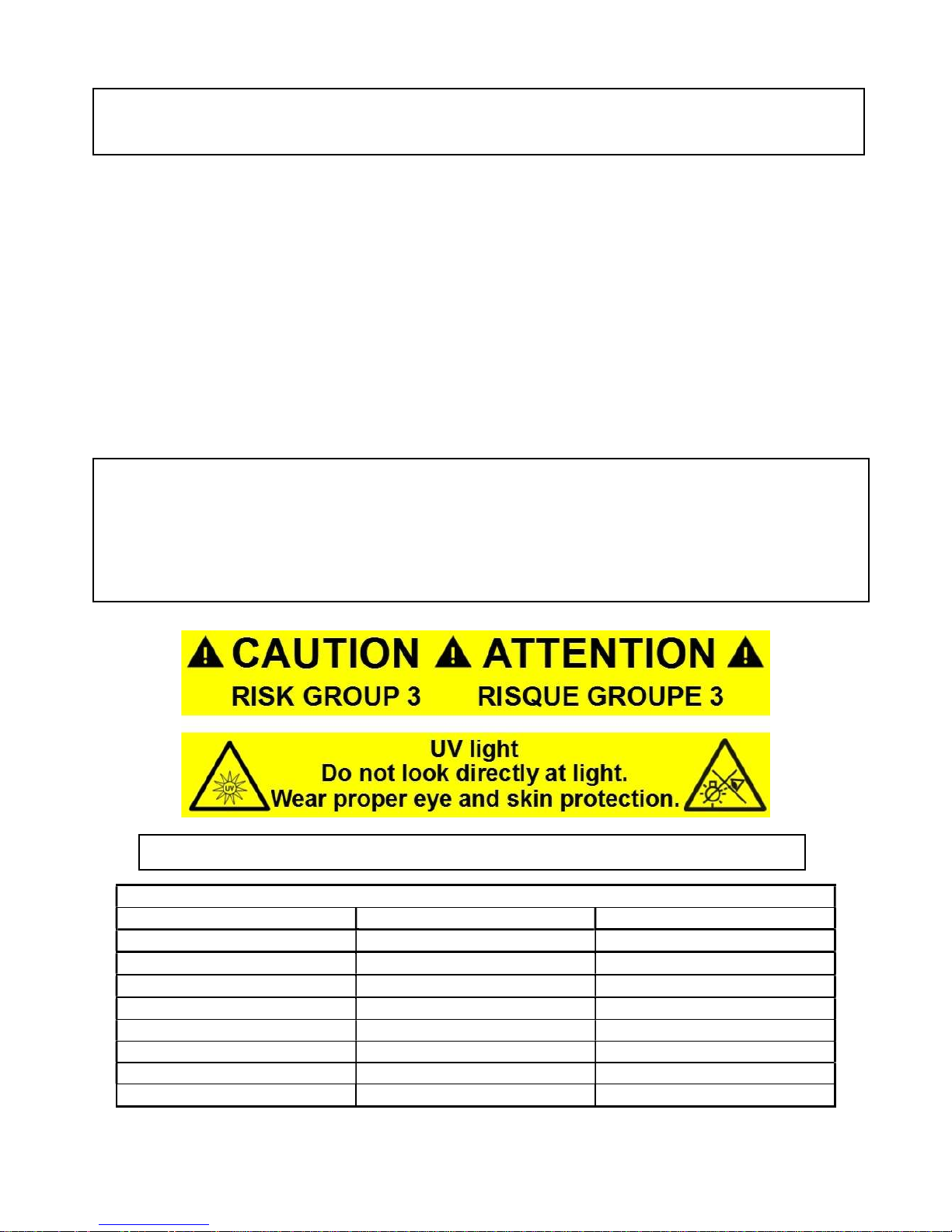
CAUTION:
Radiation exposure may cause blindness and cancer of skin!
Maximum
exposure
Distance from UV source
Fixture with clear glass
Fixture with black glass
3.5m (11.4ft) - 4m (13) - 5m (16.4ft) - 21 minutes
6m (19.7ft) 17 minutes 30 minutes
7m (23ft) 24 minutes 41 minutes
8m (26ft) 31 minutes 54 minutes
9m (29.5ft) 40 minutes 69 minutes
10m (32.8ft) 49 minutes 85 minutes
Please read an extract from a test report at the end of the user manual.

Robin CycBar UV
4
Risk Group 3 LED product according to ČSN EN 62471
.
Make sure that materials which are exposed to UV radiation will not be damaged!
Do not look at the fixture´s LEDs during operation. The light beam may damage your eyes.
Make sure that the available voltage is not higher than stated on the rear side of the fixture.
This fixture should be operated only from the type of power source indicated on the marking label. If you are not
sure of the type of power supplied, consult your authorized distributor or local power company.
Always disconnect the fixture from AC power before servicing or cleaning internally.
Do not overload supply line as this can result in fire or electric shock.
Make sure the power/data cable is never crimped or damaged by sharp edges. Check the fixture and the
power/data cable from time to time.
Do not install the unit near an open flame.
Refer servicing to qualified service personnel.
This fixture falls under protection class I. Therefore, this fixture has to be connected to a mains socket outlet
with a protective earthing connection.
Do not connect this fixture to a dimmer pack.
Keep combustible materials at least 0.3 m away from the fixture.
If the fixture has been exposed to drastic temperature fluctuation (e.g. after transportation), do not switch it on
immediately. The arising condensation of water might damage your device. Leave the device switched off until it
has reached room temperature.
Avoid brute force when installing or operating the fixture.
When choosing the installation spot, please make sure that the fixture is not exposed to extreme heat or dust.
Avoid using the unit in locations subject to possible impacts.
Do not block the front glass cover with any object when the fixture is under operation.
The fixture body must never be covered with cloth or other materials.
The fixture becomes very hot during operation. Allow the fixture to cool approximately 30 minutes prior to
servicing or maintenance.
Operate the fixture only after having familiarized yoursef with its functions. Do not permit operation by persons
not qualified to operate the fixture. Most damages are the result of unprofessional operation!
Please consider that unauthorized modifications on the fixture are forbidden due to safety reasons!
Please use the original packaging if the fixture is to be transported.
If this device will be operated in any way different to the one described in this manual, the product may suffer
damages and the warranty becomes void. Furthermore, any other operation may lead to dangers like short-circuit,
burns, electric shock etc.

Robin CycBar UV
5
2. Fixture exterior view
Warning for outdoor operation:
To keep declared ingress protection of the fixture, do not disassemble side covers (2).
Fixture´s power connectors (7, 10) are dust and water protected according to protection class IP 65 by mating with
related power connectors with cords (IP 65 rated) or by covering with the rubber sealing covers. They cannot stay
uncovered outdoor (e.g. during fixture installation).
Fixture´s DMX cable connectors are dust and water protected according to IP 65 by mating with related X-HD cable
connectors.
They cannot stay disconnected outdoor. DMX output connector (XLR female) at the last fixture in a DMX line has to
be covered with the rubber cap before inserting a terminator. The rubber cap does not supply the terminator. The
XLR terminator (male) has to be water protected.
If the fixture is to be outdoor without connecting to DMX line, always interconnect its DMX input with DMX output
to keep declared IP rating of XLR connectors.
1.
LED unit body
2. Side covers
3. Locks for tilt adjusting
4. Eyelet for safety cable
5. Mounting brackets
6. Glass transparent cover
7. DMX IN
8. Control unit
9. LED display
10. DMX OUT
11. Power IN
12. Control buttons
13. Power OUT
Robin CycBar UV
6
3. Installation
Fixtures must be installed by a qualified electrician in accordance with
all national and local electrical and construction codes and regulations.
3.1 Connection to the mains
The Robin CycBar UV is equipped with auto-switching power supply that automatically adjusts to any 50-60Hz AC
power source from 100-240 V.
If you need to install a cord cap on the power cable to allow connection to power outlets, install a grounding-type
(earthed) plug, following the plug manufacturer’s instructions.
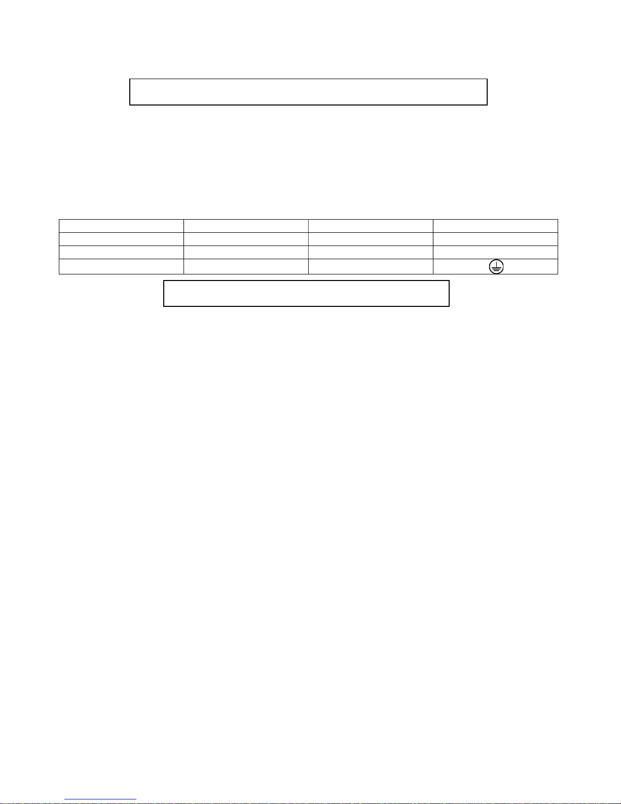
The cores in the power cable are coloured according to the following table.
Core (Eu)
Core (US)
Connection
Plug Terminal Marking
Brown
Black
Live L Light blue
White
Neutral
N
Yellow/Green Green Earth
This device falls under class one and must be grounded!
Design of the Robin CycBar UV allows to connect several fixtures to AC mains power in one interconnected daisy
chain using power input/output connectors. Needed daisy chain cables are stated in the chapter “Technical
specifications “
Max. number of connected fixtures depends on the AC mains power voltage and fixture version:
CE: US:
29 fixtures at power supply= 230V 17 fixtures at power supply= 230V
26 fixtures at power supply= 208V 15 fixtures at power supply= 208V
13 fixtures at power supply= 120V 7 fixtures at power supply= 120V
Actual numbers of fixtures may differ from values stated above as you have to take into account the length of
supply cables, circuit breaker etc. at projecting of the fixtures installation.
Do not overload the supply line and the connecting leads.
Wiring and connection work must be carried out by qualified staff!
Robin CycBar UV
7
3.2 Rigging the fixture
The Robin CycBar UV can be rigged in any orientation on a truss without altering its operation characteristics.
For overhead use, always install a safety cable that can hold at least 10 times the weight of the fixture. You must
use only a safety wire with a snap hook with screw lock gate.
Use the safety eyelet on the mounting brackets for a safety cable attachment.
Ensure that the structure (truss) to which you are attaching
the fixture is secure
Fixture may cause severe injuries when crashing down! If you have doubts concerning the safety of a possible
installation, do not install the device and consult installation with an expert.
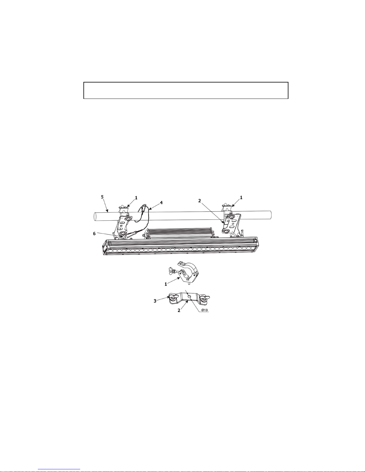
Truss installation
1. Bolt clamps (1) to the omega holders (2) with M12 bolt and lock nut through the hole in the omega holder.
2. Fasten the omega holders to the brackets of the Robin CycBar by inserting both ¼ turn quick locks (3) into
the holes of the brackets and tighten fully clockwise.
3. Clamp the fixture on a truss (5) and tighten both rigging clamps.
4. Pull a safety wire (4) around the truss (5) and lock its screw lock gate in the attachment point (6) as shown on
the picture below.
The Robin CycBar UV can also stand on two mounting brackets on a flat surface.
If you have doubts concerning the safety of a possible installation, do not install the device and consult installation
with an expert.
Robin CycBar UV
8
3.3 DMX 512 connection
The fixture is equipped with 5-pin XLR connectors for DMX input/output. Only use a shielded twisted-pair cable
designed for RS-485 and 5-pin XLR- connectors in order to connect the controller with the fixture or one fixture
with another.
Wiring of the XLR connectors:
DMX input DMX output
XLR socket: XLR plug
1 – Shield 2 - Signal (-) 3 - Signal (+) 4 – Not connected 5 – Not connected
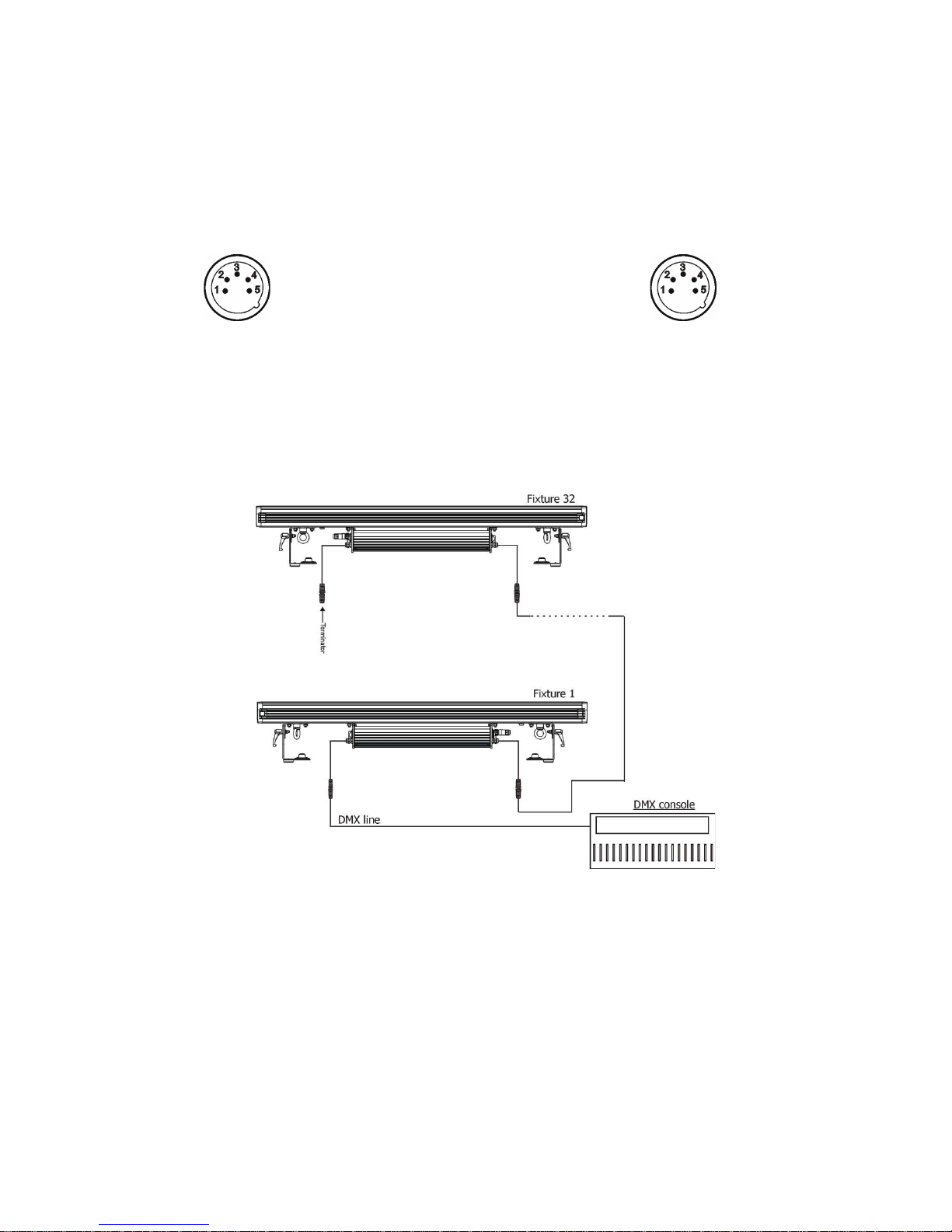
To build a DMX chain
1. Connect the DMX output of the controller directly with the DMX input of the first fixture in the DMX chain.
2. Connect the DMX output of the first fixture in the DMX chain with the DMX input of the next fixture.
3. Always connect the DMX output with the input of the next fixture until all fixtures are connected.
Do not overload the link. Max. 32 fixtures may be connected on a DMX link.
Caution: Terminate the link by installing a termination plug in the output of the last fixture. The termination plug is
a 5-pin XLR male plug with a 120 Ohm resistor soldered between Signal (–) and Signal (+).
The XLR terminator (male) has to be water protected.
 Loading...