

Page 1
Version 1.
7
Page 2

Robin CycBar 15
Table of contents
1. Safety instructions ...................................................................................................................................................... 3
2. Fixture exterior view ................................................................................................................................................... 4
3. Installation .................................................................................................................................................................. 5
3.1 Rigging the fixture ................................................................................................................................................. 5
3.2 Connection to the mains ...................................................................................................................................... 6
3.3 DMX 512 connection ............................................................................................................................................ 6
3.4 Inserting diffuser ................................................................................................................................................... 8
4. Wireless DMX operation ............................................................................................................................................. 8
5. Control menu map ...................................................................................................................................................... 9
6. Control menu ............................................................................................................................................................ 12
6.1 Fixture Address ................................................................................................................................................... 12
6.2 Fixture information ............................................................................................................................................. 12
6.3 Personality .......................................................................................................................................................... 13
6.4 Manual mode ...................................................................................................................................................... 14
6. 5 Test sequences................................................................................................................................................... 15
6.6 Stand-alone setting ............................................................................................................................................. 15
6.7 Special functions ................................................................................................................................................. 16
7. Error and information messages .............................................................................................................................. 17
8. RDM .......................................................................................................................................................................... 18
9. Technical specifications ............................................................................................................................................ 19
10. Cleaning and maintenance ..................................................................................................................................... 23
10.1 Disposing of the product .................................................................................................................................. 23
2
Page 3

Robin CycBar 15
FOR YOUR OWN SAFETY, PLEASE READ THIS USER MANUAL CAREFULLY
BEFORE POWERING OR INSTALLING YOUR Robin CycBar 15!
Save it for future reference.
This device has left our premises in absolutely perfect condition. In order to maintain this condition and to ensure a
safe operation, it is absolutely necessary for the user to follow the safety instructions and warning notes written in
this manual.
The manufacturer will not accept liability for any resulting damages caused by the non-observance of this manual
or any unauthorized modification to the device.
Please consider that damages caused by manual modifications to the device are not subject to warranty.
This device is for professional use only. It is not for household use.
1. Safety instructions
DANGEROUS VOLTAGE CONSTITUTING A RISK OF ELECTRIC SHOCK IS PRESENT WITHIN THIS UNIT!
Make sure that the available voltage is not higher than stated on the rear side of the fixture.
This fixture should be operated only from the type of power source indicated on the marking label. If you are not
sure of the type of power supplied, consult your authorized distributor or local power company.
WARNING! The unit does not contain an ON/OFF switch. Always disconnect power input cable to completely
remove power from unit when not in use or before cleaning or servicing the unit.
Do not overload wall outlets and extension cords as this can result in fire or electric shock.
Make sure that the power cord is never crimped or damaged by sharp edges. Check the fixture and the power cord
from time to time.
Do not install the unit near naked flames.
Refer servicing to qualified service personnel.
This fixture falls under protection class I. Therefore this fixture has to be connected to a mains socket outlet with
a protective earthing connection.
Do not connect this fixture to a dimmer pack.
Warning! Risk Group 2 LED product according to EN 62471.
LED light emission. Risk of eye injury. Do not look straight at the fixture´s LEDs during operation. The intense
light beam may damage your eyes. The light source contains blue LEDs.
Keep combustible materials away from the fixture.
If the fixture has been exposed to drastic temperature fluctuation (e.g. after transportation), do not switch it on
immediately. The arising condensation water might damage your device. Leave the device switched off until it has
reached room temperature.
Avoid brute force when installing or operating the fixture.
3
Page 4
Robin CycBar 15
1.
Unit body
This device is for professional use only. It is not for household use.
When choosing the installation spot, please make sure that the fixture is not exposed to extreme heat or dust.
Avoid using the unit in locations subject to possible impacts.
Only operate the fixture after having checked that the housing is firmly closed and all screws are tightly fastened.
Make sure that the area below the installation place is blocked when rigging, derigging or servicing the fixture.
Do not block the front covering glass with any object when the fixture is under operation.
The fixture body never must be covered with cloth or other materials.
Always fix the fixture with an appropriate safety cable. Fix the safety cable at the anchor point.
The fixture becomes very hot during operation. Allow the fixture to cool approximately 30 minutes prior to
manipulate with it.
Operate the fixture only after having familiarized with its functions. Do not permit operation by persons not
qualified for operating the fixture. Most damages are the result of unprofessional operation!
Do not attempt to dismantle or modify the unit.
Please consider that unauthorized modifications on the fixture are forbidden due to safety reasons!
Please use the original packaging if the fixture is to be transported.
If this device will be operated in any way different to the one described in this manual, the product may suffer
damages and the guarantee becomes void. Furthermore, any other operation may lead to dangers like shortcircuit, burns, electric shock etc.
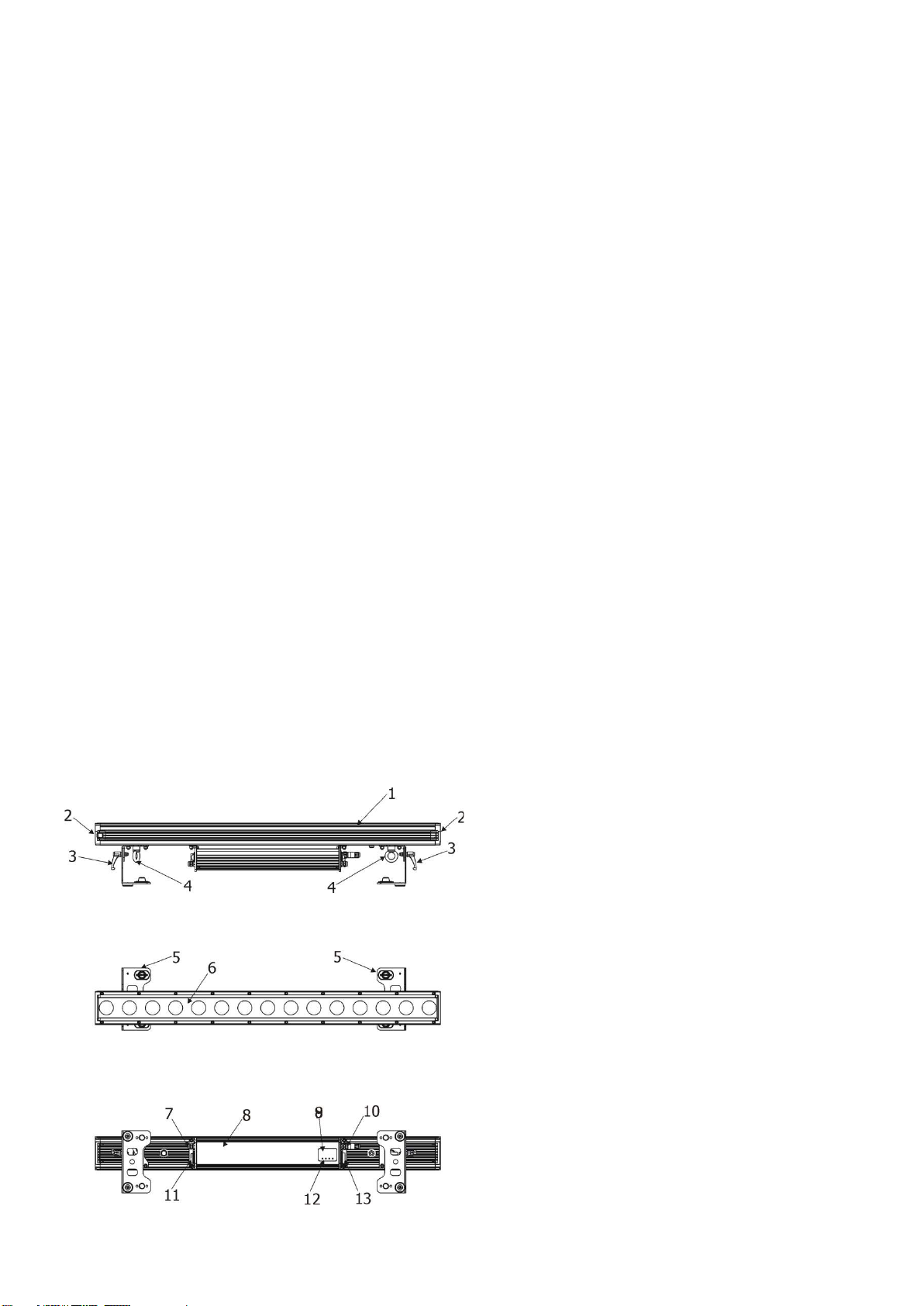
2. Fixture exterior view
2. Side covers
3. Tilt locks
4. Anchor point for safety cable
5. Mounting brackets
6. Transparent cover
7. DMX IN
8. Control unit
9. LED display
10. DMX OUT
11. Power IN
12. Control buttons
13. Power OUT
4
Page 5
Robin CycBar 15
3. Installation
3.1 Rigging the fixture
The Robin CycBar 15 can be rigged in any orientation on a truss without altering its operation characteristics.
For overhead use, always install a safety cable that can hold at least 10 times the weight of the fixture. You must
only use safety cable with screw-on carbine. Use the safety wire anchor point for safety cable attachment for this
fixture.
Ensure that the structure (truss) to which you are attaching
the fixture is secure
Fixture may cause severe injuries when crashing down! If you have doubts concerning the safety of a possible
installation, do not install the device and consult installation with an expert.
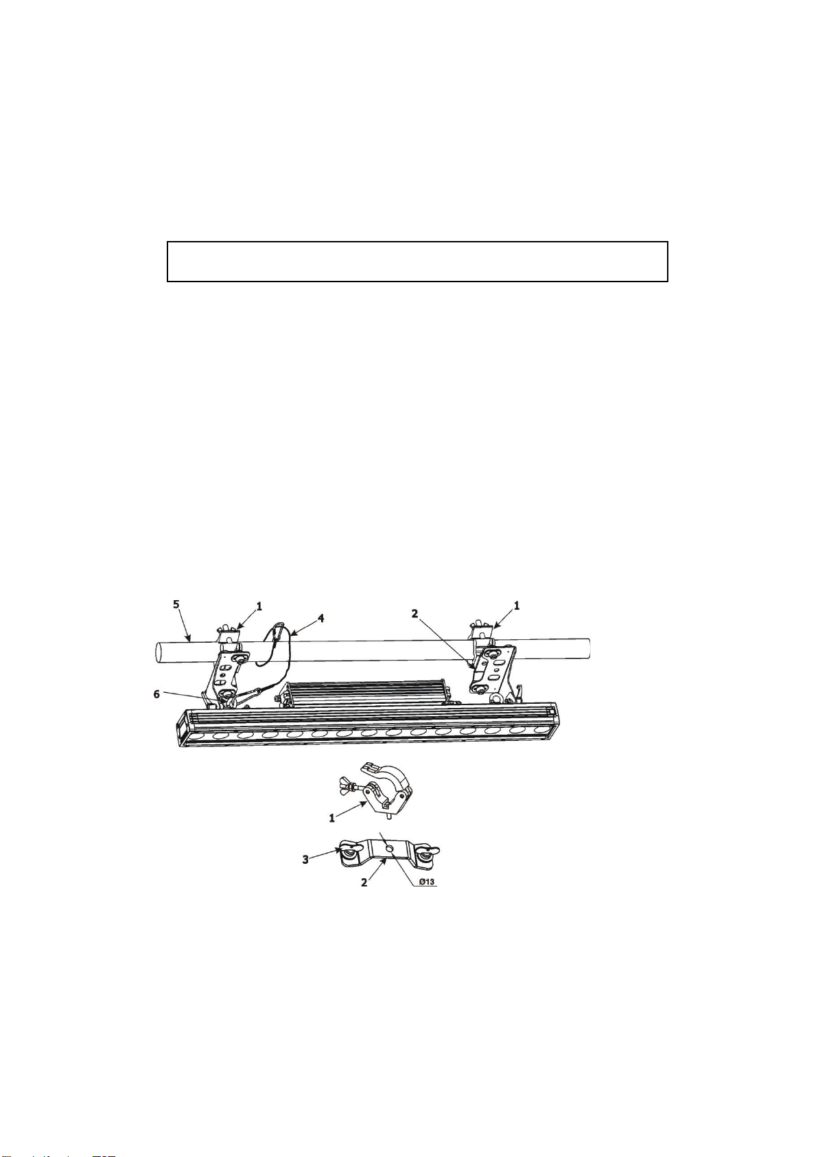
Truss installation
1. Bolt clamps (1) to the omega holders (2) with M12 bolt and lock nut through the hole in the omega holder.
2. Fasten the omega holders to the brackets of the CycBar 15 by inserting both ¼ turn quick locks (3) into
the holes of the brackets and tighten fully clockwise.
3. Clamp the fixture on a truss (5) and tighten both rigging clamps.
4. Pull a safety wire (4) around the truss (5) and lock the screw-on carabine through attachment point (6) as shown
on the picture below.
For overhead installation, the fixture must be always secured with a safety wire that can
bear at least 10 times the weight of the fixture
1- Clamp 4- safety wire
2- Omega holder 5- truss
3- ¼ turn quick locks 6- attachment point
5
Page 6
Robin CycBar 15
Core (Eu)
Core (US)
Connection
Plug
Terminal Marking
Brown
Black
Live L Light blue
White
Neutral
N
3.2 Connection to the mains
Fixtures must be installed by a qualified electrician in accordance with all national
and local electrical and construction codes and regulations.
If you install a cord cap on the power cable to allow connection to power outlets, install a grounding-type (earthed)
plug, following the plug manufacturer’s instructions.
The cores in the power cable are coloured according to the following table.
Yellow/Green Green Earth
This device falls under class one and must be grounded!
Design of the Robin CycBar 15 allows to connect several fixtures to AC mains power in one interconnected daisy
chain using power input and throughput connectors. Needed daisy chain cords are stated in the chapter
“Technical specifications “
The max. number of connected fixtures depends on the AC mains power voltage and fixture version:
EU version (CE) US version (ETL)
15 fixtures at power supply= 230V 9 fixtures at power supply= 230V
13 fixtures at power supply= 208V 7 fixtures at power supply= 208V
7 fixtures at power supply= 120V 4 fixtures at power supply= 120V
Actual numbers of fixtures may differ from values stated above as you have to take into account the length of
supply cables, circuit breaker etc. at projecting of the fixtures installation.
Do not overload the supply line and the connecting leads.
Wiring and connection work must be carried out by qualified staff!
, GND,PE
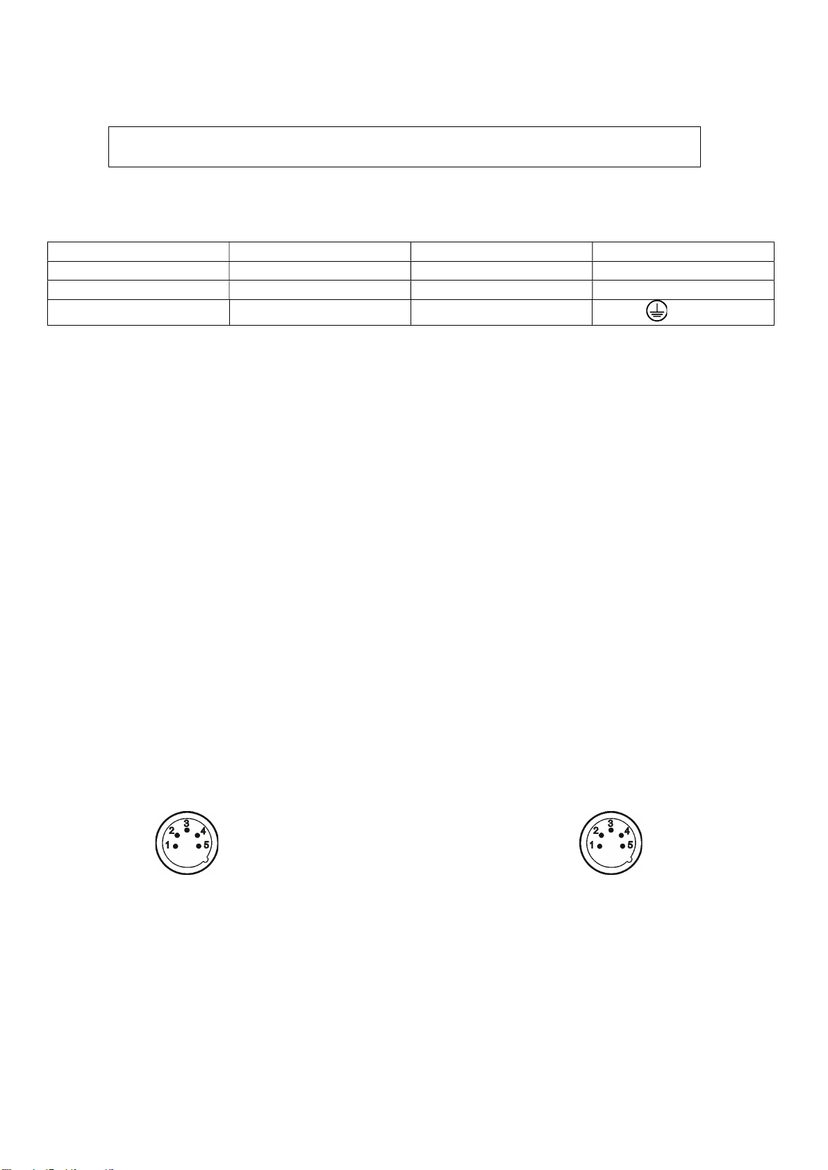
3.3 DMX 512 connection
The fixture is equipped with 5-pin XLR connectors for DMX input/output. Only use a shielded twisted-pair cable
designed for RS-485 5-pin XLR- connectors in order to connect the controller with the fixture or one fixture with
another.
Wiring of the XLR connectors:
DMX input DMX output
XLR socket: XLR plug
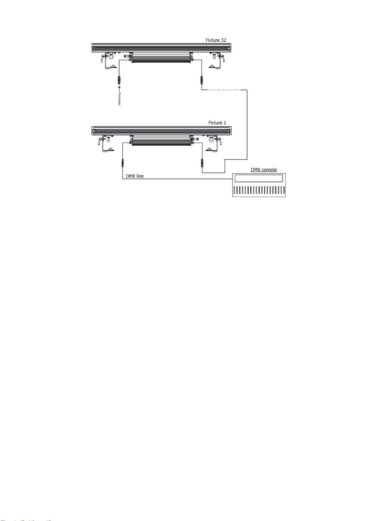
To build a DMX chain
1. Connect the DMX output of the controller directly with the DMX input of the first fixture in the DMX chain.
2. Connect the DMX output of the first fixture in the DMX chain with the DMX input of the next fixture.
3. Always connect the DMX output with the input of the next fixture until all fixtures are connected.
1 – Shield 2 - Signal (-) 3 - Signal (+) 4 – Not connected 5 – Not connected
Do not overload the link. Max. 32 fixtures may be connected on a DMX link.
6
Page 7
Robin CycBar 15
Caution: Terminate the link by installing a termination plug in the output of the last fixture. The termination plug is
a 5-pin XLR male plug with a 120 Ohm resistor soldered between Signal (–) and Signal (+).
Warning for outdoor operation!
Fixture´s XLR connectors are dust and water protected according to IP 65 by mating with related X-HD cable
connectors.
They cannot stay disconnected outdoor. DMX output connector (XLR female) at the last fixture in a DMX line has to
be covered with the rubber cap before inserting a terminator. The rubber cap does not supply the terminator. The
XLR terminator (male) has to be dust and water protected.
If the fixture is to be outdoor without connecting to DMX line, always interconnect its DMX input with DMX output
to keep declared IP rating of XLR connectors.
7
Page 8
Robin CycBar 15
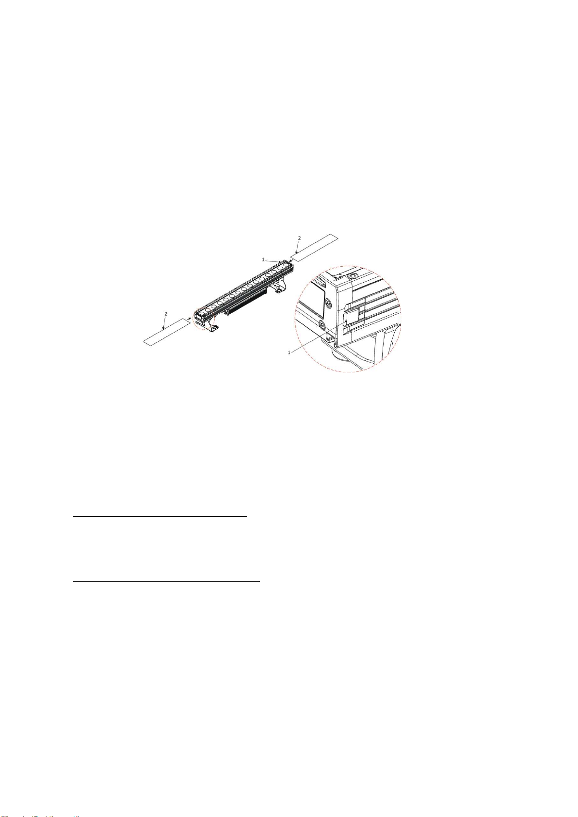
3.4 Inserting diffuser
Design of the Robin CycBar 15 allows inserting diffuser in front of the glass cover in order to change a beam angle
of the fixture. Each diffuser consist of two parts. Always insert both parts of diffuser into fixture.
Note. To keep declared ingress protection, do not disassemble side covers of the fixture!
To insert diffuser:
1. Disconnect the fixture from mains and allow it to cool.
2. Press and hold a diffuser lock (1) and insert the first part of the diffuser (2). Release the diffuser lock.
3. Press and the hold diffuser lock (1) on the opposite side of the Robin CycBar 15 and insert the second part of
the diffuser (2). Release the diffuser lock.
4. Check that both diffusers are inserted properly and cannot slide out from the fixture.
4. Wireless DMX operation
The wireless version of the CycBar 15 is equipped with the Lumen Radio CRMX module and antenna for receiving
DMX signal. CRMX module operates on the 2.4 GHz band.
1. Select option Wireless DMX input from the menu PErS (PErS-->dM.In.--> VirL.).
2. To link the fixture with DMX transmitter.
The fixture can be only linked with the transmitter by running the link procedure at DMX transmitter .
After linking , the level of DMX signal ( 0-100 %) is displayed in the menu
item “SPEC“ (SPEC-->ViFi.)
3. To unlink the fixture from DMX transmitter.
The fixture can be unlinked from receiver via the menu item “SPEC“ (SPEC-->ViFi-->UnLi.)
8
Page 9

Menu Level 1
Menu Level 2
Menu Level
3
Menu Level 4
Menu
Level 5
Menu Level 6
A001
dM.Ad.
001-512 dM.Pr.
Mod 1
:
Mod
5
InFo Poti.
totL
rSEt VErS.
IC1.b.
:
ViFi tEMP.
Cur.t.
Hi.tE.
rSEt DM.In.
Func.
0-
255 : Din.F 0-255 PErS
dM.Pr.
Mod
1
Mod.2
:
Mod.
5 dM.In
VirE
VirL
VrLo
dISP.
d.On
On,
Off d.Int.
6…
100 turn
C.CL.n.
On, OFF
5. Control menu map
Default settings=Bold print
Robin CycBar 15
9
Page 10

Robin CycBar 15
Menu Level 1
Menu Level 2
Menu Level 3
Menu Level 4
Menu Level 5
Menu
Level 6
C.MI.n.
rGbV
CMy
diM.c.
SqL
Lin VhI.c.
On,
OFF tnP.u.
°C, °F In.Po.
rEd1
0-
255 :
F.dim
0-
255 Stor.
oFrE
StAn
, HiGh
FrEq
-18..00..+18
dFSE
MAn.
C.
Func.
: di.15 tESt
St.AL.
Auto
OFF
tESt
u.PrG
PLAY
tESt
u.PrG
Edit St.1 P.End
1-35 : Func
0-
255
St.35
: :
S.tin.
0-
25.5 sec
CoPY
SPEC.
rdML
10
Page 11

Robin CycBar 15
Menu Level 1
Menu Level 2
Menu Level 3
Menu L
evel 4
Menu Level 5
Menu Level 6
rdMH
ViFi Status, UnLI
AdJ. dMH
C
.CAL C.r I : C.V 15
Stor.
uPd.M.
11
Page 12

Robin CycBar 15
6. Control menu
The Robin CycBar 15 is equipped with 4-segment LED display which allows to set the fixture´s behaviour according
to your needs, obtain information on its operation, control various range of effects and lastly program it, if it has to
be used in a stand-alone mode.
The four control buttons have the following functions:
- ESCAPE button-leaves menu without saving changes.
- ENTER button- enters menu, confirms adjusted values and leaves menu.
- UP and - DOWN buttons - move between menu items on the same level, sets values.
After switching the fixture on, display shows current DMX address.
6.1 Fixture Address
Use this menu to set the DMX address of the.
dM.Ad. --- DMX addressing. Select this submenu to set a DMX start address.
To set a DMX address.
1. Use UP/DOWN buttons to find “ A001“ menu.
2. Press the ENTER button.
3. Use the UP/DOWN buttons to select desired start address.
4. Press the ENTER button to confirm the choice.
Note: After switching on, the CycBar 15will automatically detect whether DMX 512 data is received or not.
If there is no data received at the DMX input, the display will start to flash with actually set address.
DM.Pr. --- DMX preset. Select this menu item to set a desired DMX mode. Please refer to the chapter "DMX
protocol" for detail description of each DMX mode.
Mod 1 - 16 control channels
Mod 2 - 11 control channels
Mod 3 - 61 control channels
Mod 4 - 76 control channels
Mod 5 - 47 control channels
6.2 Fixture information
Use this menu to read useful information about the fixture status.
To display desired information.
1. Use the UP/DOWN buttons to find the “ InFo“ menu.
2. Press the ENTER button.
3. Use the UP/DOWN buttons to select the required menu item.
4. Press the ENTER button to confirm the choice.
Po.ti. --- Power On Time. Use the menu item to read the number of operation hours for each LEDs operating
mode.
totL - the function shows the total number of the operation hours since the CycBar 15 has been fabricated.
rESEt - the function shows the number of the operation hours since the counter was last reset.
12
Page 13

Robin CycBar 15
In order to reset this counter to 0, you have to press and hold the UP and DOWN buttons and at the same
time press the ENTER button.
VErS. ---Software Versions. Select this function to read the software version of the fixture processors.
ICI.b. --- display processor
IC2.b. --- pixel driver
IC3.P. --- pixel control
ViFi --- Wireless DMX module
tEMP --- Fixture Temperatures. Select this menu to read the temperatures of the fixture:
Cur.t. --- the current temperature of the fixture inside.
Hi.tE. --- the menu item shows the max. temperatures of the fixture inside since
the fixture has been fabricated.
rSEt --- the menu item shows the maximum temperatures of the fixture inside since the counter
was last reset. In order to reset this counter to 0 you have to press and hold the UP and DOWN
buttons and at the same time press the ENTER button.
Note: The ambient temperature should not exceed 40°C.
The temperatures can be displayed in either °C or °F units - see option “tnP.u.“ in the menu “Pers“.
DM.In.---DMX values. Select this function to read DMX values of each channel received by the fixture.
6.3 Personality
Use this menu to modify the CycBar 15 operating behaviour.
DM.Pr. --- DMX preset. Select this menu item to set a desired DMX mode. Please refer to the chapter "DMX
protocol" for detail description of each DMX mode.
dM.In. --- DMX input. Select this menu item to select desired DMX input:
UirE --- Wire DMX.
UirL --- Wireless DMX
UrLo --- Wireless DMX –> wire DMX. The fixture receives wireless DMX signal and sends it to its
DMX output connector. Next fixtures can be connected to this fixture by DMX cable (fixture works
as a Wireless-DMX convecter.
DiSP. --- Display adjusting. This function allows you to change the display settings.
d.On --- this function allows you to keep the display on or to turn off automatically 2 minutes
after last pressing any button on the control panel.
d.Int. --- select this function to adjust the display intensity (6-min.,100-max.).
C.CL.n.
turn ---
--- Colour calibration mode. If the function is on, the white output from the fixture (and also mixed
select this function to used to rotate menu 180 degrees from current orientation
colours) is more uniform.
C.MI.n.
--- Colour mixing mode - This item allows switching into RGBW or CMY mode. In the CMY mode, the
white(8bit)/white (16) bit channels are not active.
diM.c. --- Dimmer curve. Use the menu to set desired dimmer curve:
SqL --- Square law curve.
Lin --- Linear curve.
13
.
Page 14

Robin CycBar 15
VhI.c. --- White counting. If this function is on, the white LED of each pixel lights when a white colour is mixed.
The light intensity of the white LED is in a proportion to the intensity of the rest of pixel´s LEDs (red, Green, blue)
and improves the white output of the pixel. The function influences “pixel modes” only - DMX mode 3 and 4
(RGBW colour mixing mode has to be set).
tnP.u. --- Temperature unit. Use this menu in order to display the fixture temperatures in desired units: °C or °F.
In.Po. --- Init effect positions. Use this function to set all effects to the desired positions to which they will move
after switching the fixture on (if DMX is not receiving).
oFrE. --- LEDs output frequency. The function allows you to select PWM (Pulse Width Modulation) output
frequency of LEDs from the two frequencies: StAn (Standard=300Hz)
HiGh (High=1200Hz)
FrEq. --- LEDs output frequency adjustment. The function allows you to change the selected PWM (Pulse Width
Modulation) output frequency of LEDs in 18 levels up and down around the selected frequency in the menu “oFrE”.
-18...-01 --- Frequence levels 1-18 under selected frequency.
00 --- Selected frequency (Standard or High)
+01...+18 --- Frequence levels 1-18 above selected frequency.
dF.SE. --- Default Settings .The menu item sets all fixture parameters to the default (factory) values.
6.4 Manual mode
Use this menu to control all channels via buttons of the control board.
Items in this menu depend on selected DMX mode.
To control fixture channels.
1. Use the UP/DOWN buttons to find “ Man.C“ menu.
2. Press the ENTER button.
3. Use the UP/DOWN buttons to select desired effect (channel).
List of control channels:
“Func.” – a Special functions channel
“rEd.A” – a red LEDs saturation coarse
“rE.A.F” – a red LEDs saturation fine
“GrE.A” – a green LEDs saturation coarse
“Gr.A.F” – a green LEDs saturation fine
“bLU.A” – a blue LEDs saturation coarse
“bL.A.F” – a blue LEDs saturation fine
“VhI.A” – a white LEDs saturation coarse
“Vh.A.F” – a white LEDs saturation fine
“Cto” – a colour temperature correction
“Vir.C.” – a virtual colour wheel
“PiH.E.” – pixel effects
“PH.E.S.” – a pixel effects speed
“Stro.“ - a strobe/shutter
“dinr“ - a coarse dimmer
“F.dim” a fine dimmer
“rEd.I” a red LED 1
:
“bL.15” a blue LED 15
4. Press the ENTER button and use the UP/DOWN buttons to set value , press the ENTER button to confirm it.
14
Page 15

Robin CycBar 15
6. 5 Test sequences
Use this menu to run demo-test sequences without an external controller, which will show you some possibilities
of using the CycBar 15.
6.6 Stand-alone setting
The fixtures on a data link are not connected to the controller but can execute pre-set programs which can be
different for every fixture. “Stand-alone operation” can be applied to the single fixture or to multiple fixtures
operating synchronously.
Auto. --- Automatic playback. This function allows you to select the program which will be played after switching
the fixture on. Selected program will be played continuously in a loop.
1. Use the UP/DOWN buttons to find “ St.AL.“ menu.
2. Press the ENTER button.
3. Use the UP/DOWN buttons to select “ Auto“ item.
4. Press the ENTER button.
5. Use the UP/DOWN buttons to select test program (“tESt”), user program (“u.PrG”) or disable this function
(OFF).
6. Press the ENTER button to confirm the choice.
PLAY --- Playing program. By enter to this menu a complete overview of all programs is offered, from which the
program to be run can be selected.
1. Use the UP/DOWN buttons to find “ St.AL.“ menu.
2. Press the ENTER button.
3. Use the UP/DOWN buttons to select desired program.
4. Press the ENTER button. The selected program runs in a loop.
Edit --- Editing a program. The fixture offers a freely editable program up to 35 steps. Every program step includes
a step time-the total time occupied by the step in the program.
1. Use the UP/DOWN buttons to find “ St.AL.“ menu and press the ENTER button.
2. Use the UP/DOWN buttons to select “Edit“ menu and press the ENTER button.
3. Use the UP/DOWN buttons to select a desired program step ("St.01" - "St.35") and press ENTER button.
4. Use the UP/DOWN buttons to select a channel you want to edit and press the ENTER button.
List of editable items:
“P.End” - a total number of the program steps (value 1-35). This value should be set before start
Programming (e.g. if you want to create program with 10 steps, set P.End=10).
“Func.” – a Special functions channel
“rEd.A” – a red LEDs saturation coarse
“GrE.A” – a green LEDs saturation coarse
“bLU.A” – a blue LEDs saturation coarse
“VhI.A” – a white LEDs saturation coarse
“Cto” – a colour temperature correction
“Vir.C.” – a virtual colour wheel
“PiH.E.” – pixel effects
“PH.E.S.” – a pixel effects speed
“Stro.“ - a strobe/shutter
“dinr“ - a coarse dimmer
“rEd.I” a red LED 1
:
15
Page 16

Robin CycBar 15
“bL.15” a blue LED 15
“di.15” a dimmer 15
“S.tin” a step time
“COPY“. – this item duplicates the current prog. step to the next prog. step.
Note: Items in this menu depend on selected DMX mode.
5. Use the UP/DOWN buttons to set a DMX value of the channel and then press the ENTER button.
6. Use the UP/DOWN buttons to select next channel and press the ENTER button.
7. After having set all channels in the current program step, press the ESCAPE button to go by one menu level
back and select another program step.
6.7 Special functions
rdML --- Code.This menu item shows the first part of the RDM identification code.
rdMH --- Code. This menu item shows the second part of the RDM identification code.
ViFi --- Wireless DMX. The menu serves for reading of the wireless operation status (only for Wireless DMX
version).
50 --- Wireless DMX signal. The menu item shows level of received signal in %. If the fixture is not linked to
the transmitter, “niSS” is displayed.
UnLI --- Wireless DMX unlink. The item serves for unlinking the fixture from transmitter.
AdJ --- Effect Adjustment. The menu allows calibration of white colours.
dMH --- DMX Values. The menu item allows to set desired colour before calibrating of white colours.
C.CAL ---Colour calibration. Calibration of white colours.
uPd.M. --- Updating mode. The menu item allows you to update software in the fixture via either serial or USB port
of PC.
The following items are required in order to update software:
- PC running Windows or Linux or macOS
- DSU file - Flash cable RS232/DMX, P/N13050624 (if you want to use a serial port of PC).
- Robe Universal Interface or Robe Universal interface WTX (if you want to use an USB port of PC)
After the software updating the fixture will be set to default (factory) values.
To update software in the fixture:
1. DSU file is available from the Robe web site at WWW.robe.cz.
File with extension zip is intended for Windows (used and tested from XP to W10 on 32/64bit systems).
File with extension tbz is intended for Linux (used and tested on Debian and Ubuntu 32/64bit).
File with extension dmg is intended for macOS (used and tested on OSX up to Sierra) XQuartz required,
install it from https://www.xquartz.org/.
Save the download file to a folder on your computer.
In case that you use windows, extract files in the zip file (e.g. DSU_RobinCycBar15_17010625.zip)
2. Disconnect the fixture from DMX controller.
3. If you use the flash cable RS232/DMX, connect a serial port of your computer with DMX input of the fixture
by means of the cable.
If you use the Robe Universal Interface, connect a USB port of your computer with the Robe Universal Interface
by means of the USB cable and DMX input of the fixture with the DMX output of the Robe Universal Interface
via a DMX cable.
4. Switch the fixture to the update mode (SPEC --> Upd.M.).
16
Page 17

Robin CycBar 15
Note: If you do not want to continue in the software update, you have to switch off and on the fixture to
escape from the updating mode. We recommend to cancel all running programs on your computer before
starting the software update.
5. Double-click the software uploader file (e.g. DSU_RobinCycBar15_17010625.exe) in the extracted files.
The Software Uploader program will start running.
6. Select correct "COM " number if you use a Flash cable RS232/DMX or select "Robe Universal Interface " if you
use the Robe Universal Interface/Robe Universal Interface WTX and then click on the "Connect" button.
7. If the connection is OK, click the “Start Uploading" button to start software uploading. It will take several
minutes to perform software update.
If the option "Incremental Update" is not checked, all processors will be updated (including processors with the
same software version).
If you wish to update only processors with not topical versions of software, check the “Incremental Update box“.
Avoid interrupting the process. Update status is being displayed in the "Info Box" window. When the update is
finished, the line with the text “The fixture is successfully updated“ will appear in this window.
In case upload process is interrupted (e.g. power loss), the fixture stays in “Updating mode” and you will have to
repeat the software update again.
Another way, how to update software in the fixtures (especially large installation of fixtures) is to use the ROBE
Uploader. It is a software for automatized software update of Robe and Anolis fixtures. It can take advantage of
Ethernet ports and RDM support if present in the units.
For more information please see
https://www.robe.cz/robe-uploader/.
7. Error and information messages
S.1.Er (Short 1 Error)
The message informs you that a right current was not measured in the first group of three LEDs. Some LED maybe does not
light or flashes.
S.2.Er (Short 2 Error)
The message informs you that a right current was not measured in the second group of three LEDs. Some LED maybe does not
light or flashes.
S.3.Er (Short 3 Error)
The message informs you that a right current was not measured in the third group of three LEDs. Some LED maybe does not
light or flashes.
S.4.Er (Short 4 Error)
The message informs you that a right current was not measured in the fourth group of three LEDs. Some LED maybe does not
light or flashes.
S.5.Er (Short 5 Error)
The message informs you that a right current was not measured in the fifth group of three LEDs. Some LED maybe does not
light or flashes.
17
Page 18

Robin CycBar 15
DEVICE_LABEL
* * SENSOR_DEFINITION
* SENSOR_VALUE
* DISPLAY_LEVEL
* * DEVICE_RESET
*
DMX_PERSONALITY
* * DMX_PERSONALITY_DESCRIPTION
* STATUS_MESSAGES
* STATUS_ID_DESCRIPTION
* DEVICE_HOURS
*
8. RDM
This fixture is ready for RDM operation.RDM (Remote Device Management) is a bi-directional communications
protocol for use in DMX512 control systems, it is the new open standard for DMX512 device configuration and
status monitoring.
The RDM protocol allows data packets to be inserted into a DMX512 data stream without adversely affecting
existing non-RDM equipment. By using a special „Start Code,“ and by complying with the timing specifications for
DMX512, the RDM protocol allows a console or dedicated RDM controller to send commands to and receive
messages from specific moving lights.
RDM allows explicit commands to be sent to a device and responses to be received from it.
The list of commands for the CycBar 15 is the following.
Parameter ID Discovery command SET command GET command
DISC_UNIQUE_BRANCH *
DISC_MUTE *
DISC_UN_MUTE *
DEVICE_INFO
SUPPORTED_PARAMETERS
SOFTWARE_VERSION_LABEL
DMX_START_ADDRESS
IDENTIFY_DEVICE
DEVICE_MODEL_DESCRIPTION
MANUFACTURER_LABEL
*
*
*
* *
* *
*
*
Please, see the Robe Universal Interface user manual for detail description of RDM operation.
18
Page 19

Robin CycBar 15
9. Technical specifications
Power supply
• Electronic auto-ranging
• Input voltage: 100 - 240V AC, 50-60 Hz
• Max. power consumption: 170W@230V (power factor=0.86)
• Mains input: CE - max. 16A
ETL - max. 10A
• Mains output: CE - max. 15A
ETL - max. 9A
Optic & Effects
• Light source: 15 x 10W LED multi-chip
• Beam angle: 7.5° (without diffusor), diffusor 35°x70° included as standard
• RGBW or CMY colour mixing
• Built-in colour macros and pixel effects
• Adjustable strobe sequences
•Typical Lumen maintenance: 70% @ 60.000 hours
Control
• Setting & Addressing: 4-segment LED display & 4 control buttons
• Control: USITT DMX 512 (RDM support)
• DMX protocol modes: 5 (16, 11, 61, 76, 47 control channels)
• Operations modes: DMX, Stand-alone
• Manual control of all effects via control panel
• One editable program, up to 35 steps
Wireless DMX/RDM module (only for Robin CycBar 15 Wireless DMX)
• Compliance with USITT DMX-512 (1986 & 1990) and 512-A
• Full DMX fidelity and frame integrity
• Auto sensing of DMX frame rate and frame size
• <5ms DMX latency
• Operational frequency range of 2402-2480 MHz
• Producer: LumenRadio
Strobe
• Strobe effect with variable speed (max. 20 flashes per second)
• Pre-programmed random strobe pulse-effects
Dimmer
• Smooth 16-bit dimming from 0 - 100 %
Connection
•DMX data In/Out: DMX outdoor cables CA-0611 + NC5MX-HD/NC5FX-HD (5-pin connectors)
•Power In: Neutrik NAC 3MPX
•Power Out: Neutrik NAC 3FPX
Rigging
• Via two mounting brackets
Temperatures
• Maximum ambient temperature: 40° C
• Maximum housing temperature: 80° C
19
Page 20

Robin CycBar 15
Minimum distances
Min. distance from flammable surfaces: 0.4 m
Min. distance to lighted object: 0.8 m
Total heat dissipation
• 580 BTU/h (calculated)
Weight
• 11.1 kg
Protection factor
• IP 65 (CE)
• Suitable for wet locations (ETL)
Dimensions (mm)
Included items
• 1 x Robin CycBar 15
• 1 x Omega Adaptor CL-regular 2 pcs in box (P/N10980033)
• 1 x Diffuser 35°x70° WallWasher for Robin CycBar 15/12 (P/N 10980247)
• 1 x Cap for XLR connector (P/N 19020175)
• 1 x User manual
Optional accessories
(P/N 13052 276) Mains Cable PowerCon TRUE1 In/open ended, EU 2m, outdoor
(P/N 13052 277) Mains Cable PowerCon TRUE1 In/open ended, US 2m, outdoor
(P/N 13052 278) Daisy Chain PowerCon TRUE1 In/Out, EU, 0,75m, outdoor
(P/N 13052 279) Daisy Chain PowerCon TRUE1 In/Out, US, 0,75m, outdoor
(P/N 13052 280) Daisy Chain PowerCon TRUE1 In/Out, EU, 2m, outdoor
(P/N 13052 281) Daisy Chain PowerCon TRUE1 In/Out, US, 2m, outdoor
(P/N 13052 405) Mains Cable powerCON TRUE1 In/Schuko, 2m, Indoor
(P/N 13052 406) Mains Cable powerCON TRUE1 In/US, 2m, Indoor
(P/N 13052 445) Mains Cable powerCON TRUE1 In/CEE 16A, 2m, Indoor
(P/N 13052 407) Mains Cable powerCON TRUE1 In/open ended, 2m, Indoor
(P/N 13052 439) Daisy Chain powerCON TRUE1 In/Out, EU, 2m, Indoor
(P/N 13052 440) Daisy Chain powerCON TRUE1 In/Out, US, 2m, Indoor
20
Page 21

Robin CycBar 15
(P/N 13052 444) Daisy Chain powerCON TRUE1 In/Out, EU, 5m, Indoor.
(P/N 10980 252) Diffuser 32° wash for Robin CycBar 15/12
(P/N 10980 251) Diffuser 50° wash for Robin CycBar 15/12
(P/N 10980 248) Diffuser 10°x30° Wall wash for Robin CycBar 15/12
(P/N 10980 250) Diffuser 30°x10° Cyc light for Robin CycBar 15/12
(P/N 10980 249) Diffuser 70°x35° Cyc light for Robin CycBar 15/12
(P/N 10980 269) Gel Frame set for Robin CycBar 15
(P/N 10980 421) Shield for CycBar 15, black
(P/N 10980 422Cyc Light Frame SET for CycBar 15 w/diffusors
(P/N 17030 386) Doughty Trigger Clamp
(P/N 99011 963) Safety wire 35 kg
Beam distribution
Robin CycBar 15 without diffuser
21
Page 22

Robin CycBar 15
Robin CycBar 15 with diffuser 35°x70° WallWasher
22
Page 23

Robin CycBar 15
10. Cleaning and maintenance
DANGER !
Disconnect from the mains before starting any cleaning or maintenance work
The front transparent cover will require monthly cleaning as smoke fluid tends to build up residues, reducing the
light output very quickly. For cleaning use a wet clout or an air-jet. Do not use solvents or any other aggressive
cleaning fluid.
Maintenance and service operations are only to be carried out by a qualified person or ROBE service worker only.
Should you need any spare parts, please use genuine parts.
10.1 Disposing of the product
To preserve the environment please dispose or recycle this product at the end of its life according to the local
regulations and codes.
23
Page 24

DMX protocol
Power/Special functions
To activate following functions, stop in DMX value for at
overrided.
Robin CycBar 15 - DMX protocol
Version: 1.3 Mode 1 - Standard 16-bit, Mode 2-Reduced 8-bit, Mode 3 -Extended 16-bit+RGB pixels, Mode 4 Extended 16-bit+RGBD pixels, Mode 5 -Extended 16-bit+RGBD pixels+LED Frequency Setting
Mode/channel
1 2 3 4 5
DMX
Value
Function
1 1 1 1 1
0-19 Reserved (0= default)
To activate following functions , stop in DMX value for at
least 3 sec. and shutter must be closed at least 3 sec.
(Shutter channel 14/10/2 must be at range of 0-31 DMX).
Corr esponding menu items are temporarily overrided
Type of
control
20-24 Display On
25-29 Display Off
30-39 RGBW colour mixing mode
40-49 CMY colour mixing mode
50-59 Colour calibration mode On
60-69 Colour calibration mode Off
70-89 Reserved
90-99 Dimmer curve: linear
100-109 Dimmer curve: square law
110-119 White counting On
120-129 White counting Off
least 3 seconds. Corresponding menu items are temporarily
The following function allows you to fine change of PWM output
frequency of LEDs in 18 levels Up and Down around the selected
PWM frequency (Standard, High) in the table below.
130 LED Frequency (step -18)
131 LED Frequency (step -17)
132 LED Frequency (step -16)
133 LED Frequency (step -15)
134 LED Frequency (step -14)
135 LED Frequency (step -13)
136 LED Frequency (step -12)
137 LED Frequency (step -11)
138 LED Frequency (step -10)
139 LED Frequency (step -9)
140 LED Frequency (step -8)
141 LED Frequency (step -7)
142 LED Frequency (step -6)
143 LED Frequency (step -5)
144 LED Frequency (step -4)
145 LED Frequency (step -3)
146 LED Frequency (step -2)
147 LED Frequency (step -1)
148 LED Frequency (Standard or High)
149 LED Frequency (step +1)
step
step
step
step
step
step
step
step
step
step
step
step
step
step
step
step
step
step
step
step
step
step
step
step
step
step
step
step
step
step
Page 1
Page 25

DMX protocol
* You can adjust selected frequency in 18 steps Up or Down
the fixture is Standard.
180-255
Reserved
Red/Cyan (8 bit)- all pixels
Red/Cyan (16bit)- all pixels
Green/Magenta (8 bit) - all pixels
Green/Magenta (16bit) - all pixels
Blue/Yellow (8 bit) - all pixels
Blue/ Yellow (16bit) -all pixels
White (8 bit) - all pixels
White (16 bit) - all pixels
CTO (all pixels)
Virtual colour wheel - all pixels
150 LED Frequency (step +2)
151 LED Frequency (step +3)
152 LED Frequency (step +4)
153 LED Frequency (step +5)
154 LED Frequency (step +6)
155 LED Frequency (step +7)
156 LED Frequency (step +8)
157 LED Frequency (step +9)
158 LED Frequency (step +10)
159 LED Frequency (step +11)
160 LED Frequency (step +12)
161 LED Frequency (step +13)
162 LED Frequency (step +14)
163 LED Frequency (step +15)
164 LED Frequency (step +16)
165 LED Frequency (step +17)
166 LED Frequency (step +18)
167-169 Reserved
170-174 PWM output frequency of LEDS: Standard (300Hz)*
175-179 PWM output frequency of LEDS: High (1200Hz)*
step
step
step
step
step
step
step
step
step
step
step
step
step
step
step
step
step
step
step
2 2 2 2 *
3 * 3 3 *
4 3 4 4 *
5 * 5 5 *
6 4 6 6 *
7 * 7 7 *
8 5 8 8 *
9 * 9 9 *
10 6 10 10 *
11 7 11 11 *
around selected frequency. Default value of PWM frequency set in
0 - 255 Colour saturation control - coarse 0-100% (255=default) proportional
0 - 255 Colour saturation control - fine (255=default) proportional
0 - 255 Colour saturation control - coarse 0-100% (255=default) proportional
0 - 255 Colour saturation control - fine (255=default) proportional
0 - 255 Colour saturation control - coarse 0-100% (255=default) proportional
0 - 255 Colour saturation control - fine (255=default) proportional
If RGBW mode is selected:
0-255 Colour saturation control - coarse 0-100% (255=default) proportional
If CMY mode is selected:
0 - 255 No function
0 - 255 Colour saturation control - fine (255=default) proportional
No function (0=255)
0
1-255
1-2 White 2700 K
Colour temperature correction
0 No function (0=default)
3 White 2700 K (tungsten emulation)*
proportional
step
step
step
Page 2
Page 26

DMX protocol
Pixel effects
Pixel effects speed
Shutter/ strobe - all pixels
Dimmer intensity (8 bit) -all pixels
Dimmer intensity fine (16 bit) -all pixels
Red pixel 1
Green pixel 1
12 8 12 12 *
13 9 13 13 *
14 10 14 14 2
15 11 15 15 *
16 * 16 16 *
* * 17 17 3
* * 18 18 4
4-5 White 3200 K
6 White 3200 K (tungsten emulation)*
7-9 White 4200 K
10-12 White 5600 K
13-15 White 8000 K
16 Blue (Blue=full, Red+Green+White=0)
17-55 Red=0, Greenup,Blue =full, White=0
56 Light Blue (Red=0, Green=full, Blue =full, white=0)
57 - 95 Red=0, Green=full, Bluedown, White=0
96 Green (Red=0, Green=full, Blue =0, White=0)
97 – 134 Red up, Green=full, Blue=0, White=0
135 Yellow (Red=full, Green=full, Blue=0,White=0)
136 - 174 Red=full, Greendown, Blue=0, White=0
175 Red(Red=full, Green=0, Blue=0, White=0)
176 -214 Red=full, Green=0, Blueup, White=0
215 Magenta (Red=full, Green=0, Blue=full, White=0)
216 - 246 Reddown, Green=0, Blue=full, White=0
247 Blue (Red=0, Green=0, Blue=full, White=0)
248-251 Rainbow effect( with fade time) from min.->max. speed
step
step
step
step
step
step
proportional
step
proportional
step
proportional
step
proportional
step
proportional
step
proportional
step
proportional
252-255 Rainbow effect(without fade time)from min.->max.speed proportional
0-2 No function (0=default)
3-4 Effect 1 step
5-6 Effect 2 step
: : :
181-182 Effect 90 step
183-255 Reserved
0-63 Speed from min. —>max. without fade time (0=default)
64-127 Speed from max. —>min. without fade time (op. direction)
128-191 Speed from min. —>max. with fade time
proportional
proportional
proportional
192-255 Speed from max. —>min. with fade time (op. direction) proportional
0 - 31 Shutter closed step
32 - 63 Shutter open (32=default) step
64 - 95 Strobe-effect from slow to fast proportional
96 - 127 Shutter open step
128 - 143 Opening pulse in sequences from slow to fast proportional
144 - 159 Closing pulse in sequences from fast to slow proportional
160 - 191 Shutter open step
192 - 223 Random strobe-effect from slow to fast proportional
224 - 255 Shutter open step
0 - 255 Dimmer intensity from 0% to 100% (0=default) proportional
0 - 255 Fine dimming (0=default) proportional
0-255 Red LED saturation control 0-100% (0=default) proportional
0-255 Green LED saturation control 0-100% (0=default) proportional
Page 3
Page 27

DMX protocol
Blue pixel 1
Dimmer 1
Red pixel 15
Green pixel 15
Blue pixel 15
Dimmer 15
Copyright © 2015-2018 Robe Lighting s.r.o. - All rights reserved
All Specifications subject to change without notice
* * 19 19 5
0-255 Blue LED saturation control 0-100% (0=default) proportional
* * * 20 *
0-255 Dimmer intensity control 0-100% (0=default) proportional
:
* * 59 73 45
0-255 Red LED saturation control 0-100% (0=default) proportional
* * 60 74 46
0-255 Green LED saturation control 0-100% (0=default) proportional
* * 61 75 47
0-255 Blue LED saturation control 0-100% (0=default) proportional
* * * 76 *
0-255 Dimmer intensity control 0-100% (0=default) proportional
* In the Tungsten effect simulation the Dimmer channel imitates behaviour of the halogen lamp during dimming
Page 4
Page 28

DMX value
Effect
Type of Control
0-2 No function
Step
3-4
Effect 1
Step
5-6
Effect 2
Step
7-8
Effect 3
Step
9-10
Effect 4
Step
11-12
Effect 5
Step
13-14
Effect 6
Step
15-16
Effect 7
Step
17-18
Effect 8
Step 19-20 Effect 9
Step
21-22
Effect 10
Step
23-24
Effect 11
Step
25-26
Effect 12
Step
27-28
Effect 13
Step
29-30
Effect 14
Step
31-32
Effect 15
Step
33-34
Effect 16
Step
35-36
Effect 17
Step
37-38
Effect 18
Step
39-40
Effect 19
Step
41-42
Effect 20
Step
43-44
Effect 21
Step
45-46
Effect 22
Step
47-48
Effect 23
Step
49-50
Effect 24
Step
51-52
Effect 25
Step
53-54
Effect 26
Step
55-56
Effect 27
Step
57-58
Effect 28
Step
Colour channels priority:
1. Pixel effects channel
2. Virtual colour wheel channel
3. RGBW ALL PIXELS channels
4. If some colour from RGBW ALL PIXELS is set at 0 DMX, this colour can be set individually on each
pixel 1-15 using R1G1B1….R15G15B15.
Pixels order
Pixel effects:
Robin CycBar 15
24
Page 29

Robin CycBar 15
DMX value
Effect
Type of Control
59-60
Effect
29
Step
61-62
Effect 30
Step
63-64
Effect 31
Step
65-66
Effect 32
Step
67-68
Effect 33
Step
69-70
Effect 34
Step
71-72
Effect 35
Step
73-74
Effect 36
Step
75-76
Effect 37
Step
77-78
Effect 38
Step
79-80
Effect 39
Step
81-82
Effect 40
Step
83-84
Effect 41
Step
85-86
Effect 42
Step
87-88
Effect 43
Step
89-90
Effect 44
Step
91-92
Effect 45
Step
93-94
Effect 46
Step
95-96
Effect 47
Step
97-98
Effect 48
Step
99-
100 Effect 49
Step
101-102 Effect 50
Step
103-104 Effect
51 Step
105-106 Effect 52
Step
107-108 Effect 53
Step
109-110 Effect 54
Step
111-112 Effect 55
Step
113-114 Effect 56
Step
115-116 Effect 57
Step
117-118 Effect 58
Step
119-120 Effect 59
Step
121-122 Effect 60
Step
123-124 Effect 61
Step
125-126 Effect 62
Step
127-128 Effect 63
Step
129-130 Effect 64
Step
131-132 Effect 65
Step
133-134 Effect 66
Step
135-136 Effect 67
Step
137-138 Effect 68
Step
139-140 Effect 69
Step
141-142 Effect 70
Step
143-144 Effect 71
Step
145-146 Effect 72
Step
147-148 Effect 73
Step
149-150 Effect 74
Step
151-152 Effect 75
Step
153-154 Effect 76
Step
155-156 Effect 77
Step
157-158 Effect 78
Step
159-160 Effect 79
Step
25
Page 30

Robin CycBar 15
DMX value
Effect
Type of Control
161-162 Effect 80
Step
163-164 Effect 81
Step
165-166 Effect 82
Step
167-168 Effect 83
Step
169-170 Effect 84
Step
171-172 Effect 85
Step
173-174 Effect 86
Step
175-176 Effect 87
Step
177-178 Effect 88
Step
179-180 Effect 89
Step
181-182 Effect 90
Step
183-255 Reserved
Janury 28, 2019
Copyright © 2015-2019 Robe Lighting - All rights reserved
All Specifications subject to change without notice
Made in ROBE Lighting s.r.o., Palackého 416, 757 01 Valašské Meziříčí, Czech Republic
26
 Loading...