

Page 1
1
Version 1.1
Page 2

2
Table of contents
1. Safety instructions ......................................................................................................... 3
2. Fixture exterior view ...................................................................................................... 5
3. Installation....................................................................................................................... 6
3.1 Connection to the mains ............................................................................................ 6
3.2 Installing the gel frame and barndoors ....................................................................... 7
3.3 Rigging the xture and oor installation of the xture ................................................ 8
3.4 DMX-512 connection ................................................................................................ 13
3.5 Ethernet connection ................................................................................................. 14
4. Control menu map ........................................................................................................ 16
5. DMX chart ...................................................................................................................... 18
6. Strobe and Special eects running ........................................................................... 20
6.1 Strobe ...................................................................................................................... 20
6.2 Special eects ......................................................................................................... 20
7. Control menu ............................................................................................................... 22
7.1 Tab " Address" .......................................................................................................... 23
7.2 Tab "Information" ...................................................................................................... 24
7.3 Tab "Personality" ......................................................................................................25
7.4 Tab "Manual Control" ................................................................................................ 26
7.5 Tab "Stand-alone" .................................................................................................... 26
7.6 Tab "Service" ............................................................................................................ 27
8. RDM ............................................................................................................................... 28
9. Wireless DMX operation .............................................................................................. 28
10. Error and information messages .............................................................................. 29
11. Technical Specications ............................................................................................ 30
12. Maintenance and cleaning ......................................................................................... 32
12.1 Replacing fuse ....................................................................................................... 33
12.2 Disposing of the product ........................................................................................ 33
13. Appendix ..................................................................................................................... 33
13.1 Strobe and Special eects timing .......................................................................... 33
Robin ColorStrobe Lite
Page 3
3
FOR YOUR OWN SAFETY, PLEASE READ THIS USER MANUAL CAREFULLY
BEFORE POWERING OR INSTALLING YOUR ROBIN ColorStrobe Lite !
Save it for future reference.
This device has left our premises in absolutely perfect condition. In order to maintain this condition and to ensure a safe operation, it is absolutely necessary for the user to follow the safety instructions and warning notes
written in this manual.
The manufacturer will not accept liability for any resulting damages caused by the non-observance of this manual or any unauthorized modication to the device.
Please consider that damages caused by manual modications to the device are not subject to warranty.
The Robin ColorStrobe Lite was designed for indoor use and it is intended for
professional applications only. It is not for household use.
1. Safety instructions
DANGEROUS VOLTAGE CONSTITUTING A RISK OF ELECTRIC SHOCK IS PRESENT WITHIN THIS UNIT!
Make sure that the available voltage is not higher than stated on the rear panel of the xture.
This xture should be operated only from the type of power source indicated on the marking label. If you are
not sure of the type of power supplied, consult your authorized distributor or local power company.
WARNING! This unit does not contain an ON/OFF switch. Always disconnect power input cable to completely
remove power from unit when not in use or before cleaning or servicing the xture.
The power plug has to be accessible after installing the xture. Do not overload wall outlets and extension cords
as this can result in re or electric shock.
Do not allow anything to rest on the power cord. Do not locate this xture where the cord may be damaged by
persons walking on it.
Make sure that the power cord is never crimped or damaged by sharp edges. Check the xture and the power
cord from time to time.
Refer servicing to qualied service personnel.
This xture falls under protection class I. Therefore this xture has to be connected to
a mains socket outlet with a protective earthing connection.
Do not connect this xture to a dimmer pack.
Warning! Risk Group 2 LED product according to EN 62471
LED light emission. Risk of eye injury. Do not look into the beam at short distance of
the of the product. Do not view the light output with optical instruments or any device
that may conncentrate the beam
To guard against epileptic seizure:
Do not operate the xture near stairways. Provide advance notice that
ColorStrobe lighting is in use. Avoid extended periods of continuous ashing, particu-
larly at frequencies of 10 to 20 ashes per second
If the xture has been exposed to drastic temperature uctuation (e.g. after transportation), do not switch it on
Page 4
4
immediately. The arising condensation water might damage your device. Leave the device switched o until
it has reached room temperature.
Do not shake the xture. Avoid brute force when installing or operating the xture.
When choosing the installation spot, please make sure that the xture is not exposed to extreme heat, moisture
or dust.
Air vents and slots in the xture are provided for ventilation, to ensure reliable operation of the device and to
protect it from overheating.The openings should never be covered with cloth or other materials, and never
must be blocked.
This xture should not be placed in a built-in installation unless proper ventilation is provided.
Never place lters or other materials over the front glass cover.
Only operate the xture after having checked that the housing is rmly closed and all screws are tightly fastened.
To avoid damage of the internal optical system of the xture, never let the sunlight
lights directly to the lens array, even when the xture is not working !
Keep ammable materials well away from the xture.
Do not illuminate surfaces within 1 meter of the xture.
Provide a minimum clearance of 0.3 meters around air vents
Always use a secondary safety cable when rigging this xture.
Make sure that the area below the installation place is blocked when rigging, derigging or servicing the xture.
The xture becomes very hot during operation. Allow the xture to cool approximately 20 minutes prior to manipulate with it.
Operate the xture only after having familiarized with its functions. Do not permit operation by persons not
qualied for operating the xture. Most damages are the result of unprofessional operation!
Please use the original packaging if the xture is to be transported.
Please consider that unauthorized modications on the xture are forbidden due to safety reasons!
If this device will be operated in any way dierent to the one described in this manual, the product may suer
damages and the guarantee becomes void. Furthermore, any other operation may lead to dangers like short-
-circuit, burns, electric shock, crash etc.
Page 5
5
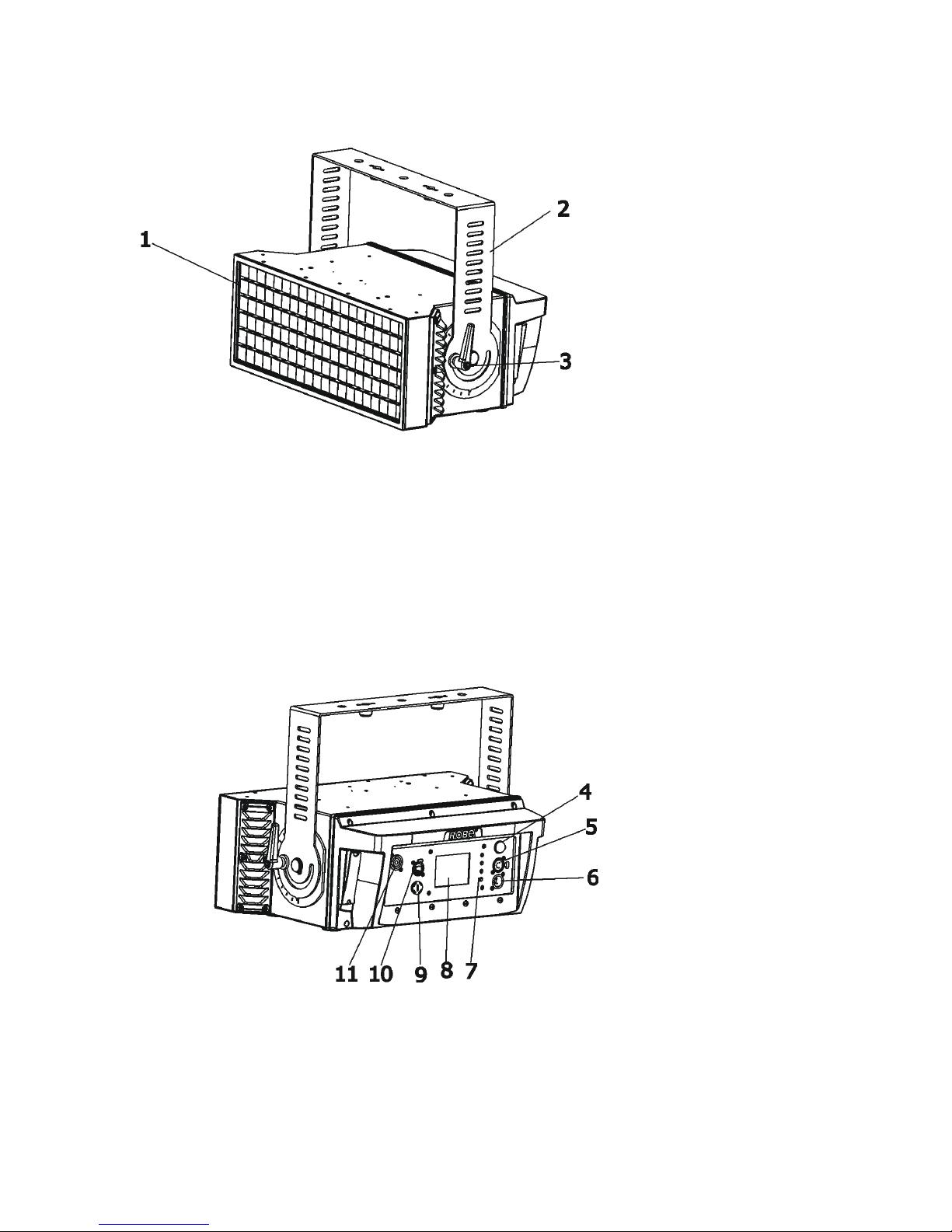
2. Fixture exterior view
4 - Antenna
5 - DMX IN
6 - DMX OUT
7 - Control buttons
8 - QVGA touch screen
9 - Fuse holder
10 - RJ 45 Input
11 - Power
1 - Glass cover and lens array
2 - U-holder
3 - Tilt lock
The ENTER/DISPLAY ON button also serves for switching the display on when the xture is disconnected
from mains.
Page 6
6
3. Installation
Fixtures must be installed by a Qualied electrician in accordance with all
national and local electrical and construction codes and regulations.
3.1 Connection to the mains
For protection from electric shock, the xture must be earthed!
The Robin ColorStrobe Lite is equipped with auto-switching power supply that automatically adjusts to any 5060Hz AC power source from 100-240 Volts.
Connect the xture to the mains by means of the enclosed power cord
If you need to install other plug on the power cord, note that the cores in the power cord are coloured according
to the following table. The earth has to be connected!
If you have any doubts about proper installation, consult a qualied electrician.
Core (EU) Core (US) Connection Plug Terminal Marking
Brown Black Live L
Light blue White Neutral N
Yellow/Green Green Earth
Do not overload the supply line and the connecting leads.
Wiring and connection work must be carried out by a qualied sta!
Page 7
7
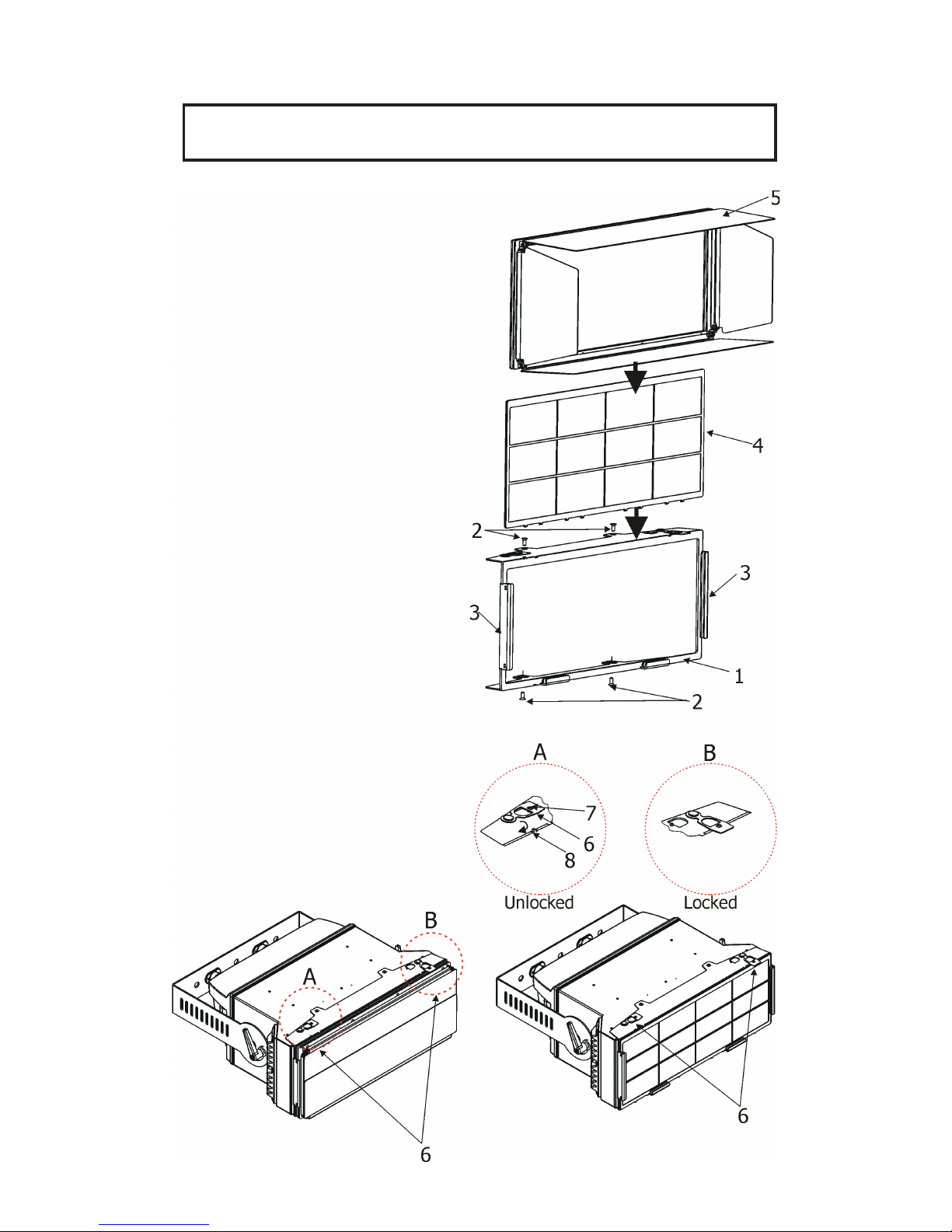
3.2 Installing the gel frame and barndoors
Disconnect the xture from mains before the accessory installation.
Never operate the xture with barndoors closed.
1. Put the frame adaptor (1) on the xture and
secure it with four screws (2).
2. Insert the gel frame (4) into slots (3) of
the frame adaptor (1). Use the slots closer to
the glass cover of the xture.
3. Insert the barndoors (5) into second slots (3) of
the frame adaptor (1).
4. Secure inserted barndoors and (or) the gel
frame by means of the two locks (6).
Lift up a little the lock (6) to release it from
the projection (7) and move it to the position
as shown on the picture B until the projection (8)
snaps into lock (6).
Do not operate the xture with unsecured gel
frame or barndoors!
Page 8
8
3.3 Rigging the xture and oor installation of the xture
A structure intended for installation of the xture (s) must safely hold weight of the xture(s) placed on it. The
structure has to be certicated to the purpose.
The xture (xtures) must be installed in accordance with national and local electrical and construction codes
and regulation..
For overhead installation, the xture must be always secured with a safety wire
that can bear at least 10 times the weight of the xture.
When rigging, derigging or servicing the xture staying in the area below the installation place, on bridges,
under high working places and other endangered areas is forbidden.
The operator has to make sure that safety-relating and machine-technical installations are approved by an
expert before taking into operation for the rst time and after changes before taking into operation another time.
The operator has to make sure that safety-relating and machine-technical installations are approved by a skilled
person once a year.
Allow the xture to cool for ten minutes before handling.
The xture should be installed outside areas where persons may walk by or be seated.
IMPORTANT! OVERHEAD RIGGING REQUIRES EXTENSIVE EXPERIENCE, including calculating working
load limits, installation material being used, and periodic safety inspection of all installation material and the
projector. If you lack these qualications, do not attempt the installation yourself, but use a help of professional
companies.
CAUTION: Fixtures may cause severe injuries when crashing down! If you have doubts concerning the safety
of a possible installation, do not install the xture!
The xture has to be installed out of the reach of public.
The xture must never be xed swinging freely in the room.
When installing the device, make sure there is no highly inammable
material (decoration articles, etc.) in a distance of min. 0.5 m.
CAUTION!
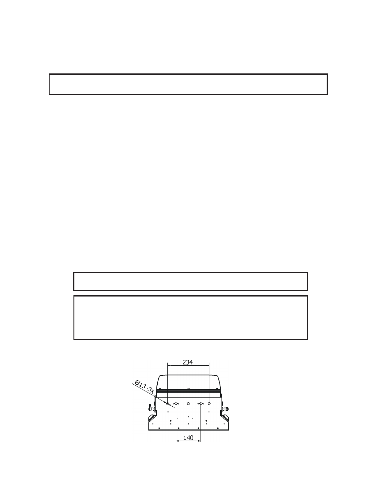
Use an appropriate clamp to rig the xture on the truss.
Follow the instructions mentioned at the bottom of the xture base.
Make sure that the device is xed properly! Ensure that the
structure (truss) to which you are attaching the xture is secure.
The xture can be rigged to the truss via the Omega holder and one clamp (two holes with 140mm spacing
serves for the Omega holder) or stand directly on the oor.
.
Page 9
9
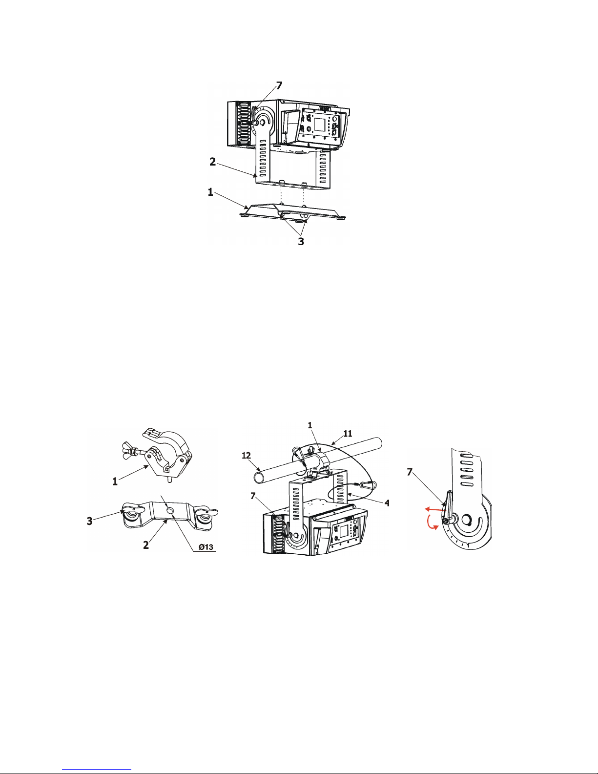
Floor installation via the oor stand
1. Fasten the oor stand (1) to the U-holder (2) of the xture by means of two 1/4 turn locks (3).
2. The tilt lock (7) allows to adjust the xture to desired position.
Rigging the xture via the omega holder
1. Bolt the clamp (1) to the omega holder (2) with M12 bolt and lock nut through the hole in the holder.
2. Fasten the omega holder to the U-holder (4) of the xture by inserting both quick-lock fasteners (3) into
holes in the U-holder and tighten fully clockwise.
3. Clamp the xture on a truss (12) and tighten the rigging clamp (1).
4. For securing the xture to the truss, install a safety wire that can hold at least 10 times the weight
of the xture. Use only a safety wire with a snap hook with screw lock gate. Pull the safety
wire (11) through the U-holder (4) and around the truss (12) as shown on the picture below.
5. The tilt lock (7) allows to adjust the xture to desired position. In case, that the tilt lock cannot
be loosened (tightened) due to the housing of the xture, pull this tilt lock in a direction from the xture,
turn it to desired position, release it and continue in loosening (tightening) this tilt lock (principle of
a "ratcheting socket wrench").
Page 10
10
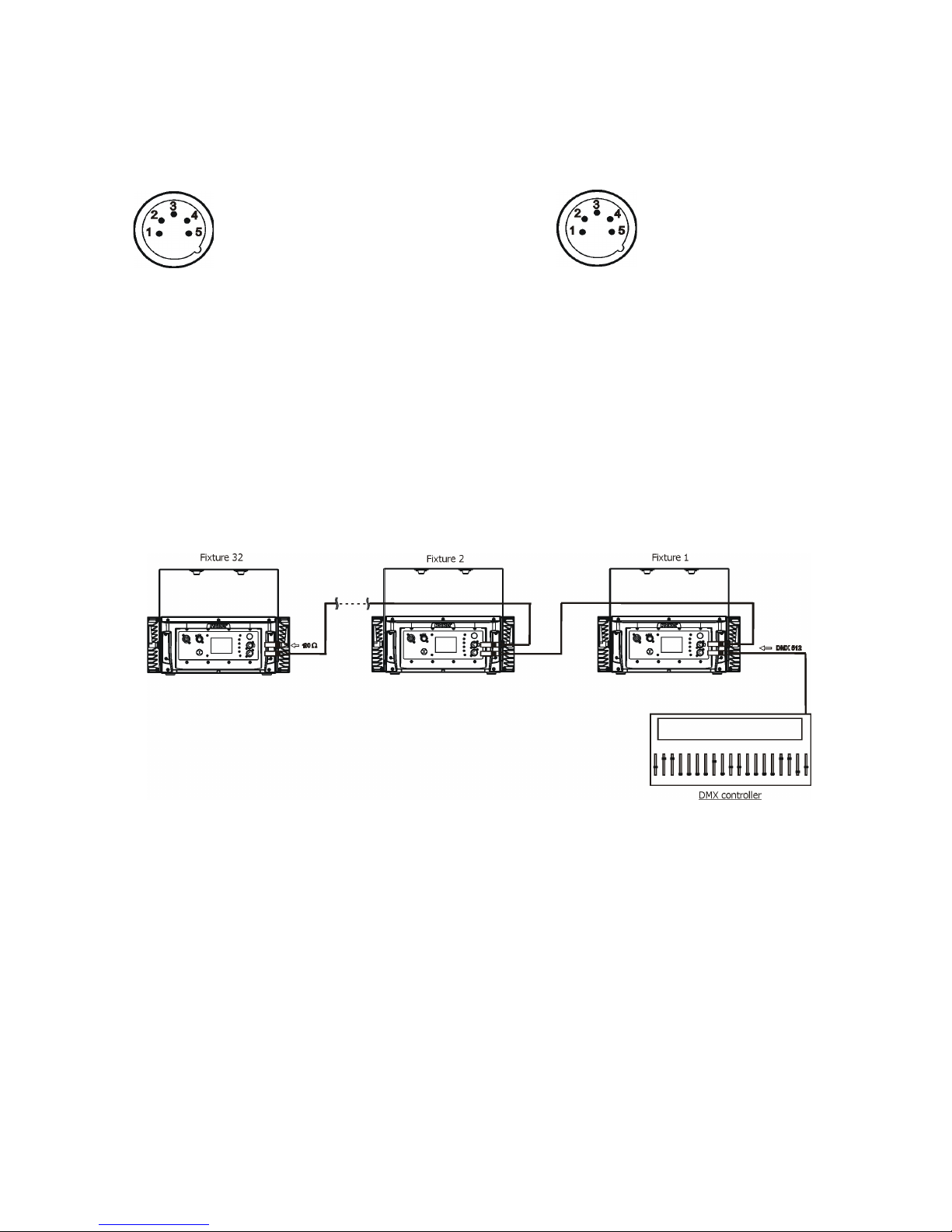
3.4 DMX-512 connection
The xture is equipped with 5-pin XLR sockets for DMX input and output.The sockets are wired in parallel.
Only use a shielded twisted-pair cable designed for RS-485 and 5-pin XLR-plugs and connectors in order to
connect the controller with the xture or one xture with another.
DMX - output DMX-input
If you are using the standard DMX controllers, you can connect the DMX output of the controller directly with
the DMX input of the rst xture in the DMX-chain. If you wish to connect DMX controllers with other
XLR-outputs, you need to use adapter cables.
Building a serial DMX-chain:
Connect the DMX output of the rst xture in the DMX-chain with the DMX input of the next xture. Always connect
one output with the input of the next xture until all xtures are connected. Up to 32 xtures can be connected.
Caution: At the last xture, the DMX cable should be terminated with a terminator. Solder a 120 Ω resistor
between Signal (–) and Signal (+) into a 5-pin XLR-plug and plug it in the DMX output of the last xture.
1 - Shield
2 - Signal (-)
3 - Signal (+)
4 - Used for wireless DMX
5 - Used for wireless DMX
1 - Shield
2 - Signal (-)
3 - Signal (+)
4 - Used for wireless DMX
5 - Used for wireless DMX
Page 11
11
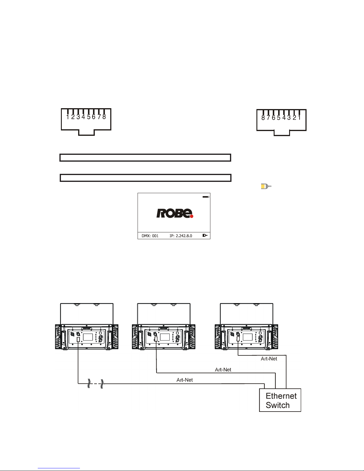
3.5 Ethernet connection
The xtures on a data link are connected to the Ethernet with ArtNet communication protocol.The control software running on your PC (or light console) has to support Art-Net protocol.
Art-Net communication protocol is a 10 Base T Ethernet protocol based on the TCP/IP.Its purpose is to allow
transfer of large amounts of DMX 512 data over a wide area using standard network technology.
IP address is the Internet protocol address.The IP uniquely identies any node (xture) on a network.
The Universe is a single DMX 512 frame of 512 channels.
The Robin 300E Wash is equipped with 8-pin RJ- 45 socket for Ethernet input.Use a network cable category 5
(with four “twisted” wire pairs) and standard RJ-45 plugs in order to connect the xture to the network.
RJ-45 socket (front view): RJ-45 plug (front view):
1- TD+ 5- Not connected
2- TD- 6- RX-
3- RX+ 7- Not connected
4- Not connected 8- Not connected
Patch cables that connect xtures to the hubs or LAN sockets are wired 1:1,that is,pins with the same numbers
are connected together:
1-1 2-2 3-3 4-4 5-5 6-6 7-7 8-8
If only the xture and the computer are to be interconnected,no hubs or other active components are needed.A
cross-cable has to be used:
1-3 2-6 3-1 4-8 5-7 6-2 7-5 8-4
If the xture is connected with active Ethernet socket (e.g. switch) the network icon will appear at the
bottom right corner of the screen:
Direct Ethernet operation
Connect the Ethernet inputs of all xtures with the Ethernet network.
Option “ Artnet (gMaI or gMA2)" has to be selected from “Ethernet Mode” menu on the xture.
Set IP address (002.xxx.xxx.xxx / 010.xxx.xxx.xxx) and the Universe.
(DMX address=186) (DMX address=38) (DMX address=1)
IP addres=002.168.002.004 IP addres=002.168.002.003 IP addres=002.168.002.002
Universe=1 Universe=1 Universe=1
An advised PC setting: IP address: 002.xxx.xxx.xxx / 010.xxx.xxx.xxx (Dierent from xture IP addresses)
NET mask: 255.0.0.0
Page 12
12
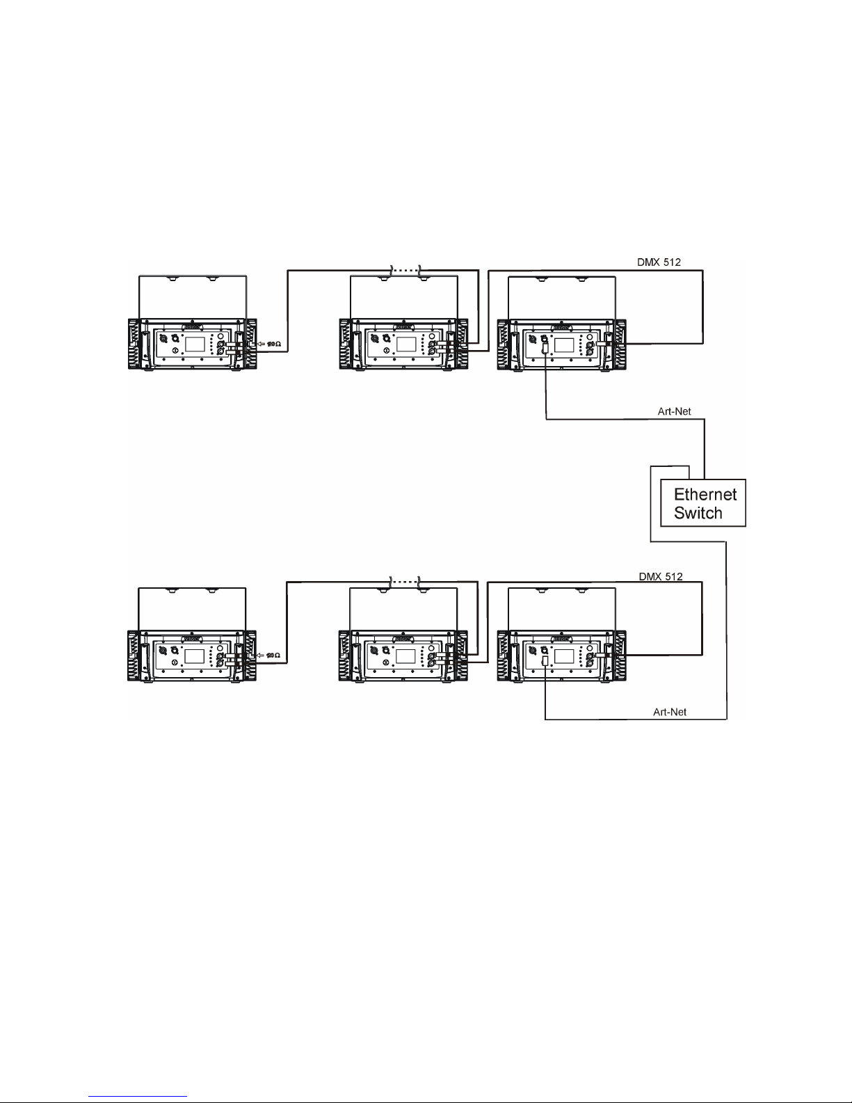
Ethernet / DMX operation
Option “ Artnet" (gMaI or gMA2 or sACN) has to be selected from “Ethernet Mode” menu at rst xture.
Option “Ethernet To DMX” has to be selected from the “Ethernet Mode” menu at the rst xture (connected to
the Ethernet) in the xture chain, next xtures have standard DMX setting.
Connect the Ethernet-input of the rst xture in the data chain with the network. Connect the DMX output of
this xture with the input of the next xture until all xtures are connected to the DMX chain.
Caution: At the last xture, the DMX chain has to be terminated with a terminator. Solder a 120 Ω resistor
between Signal (–) and Signal (+) into a XLR-plug and connect it in the DMX-output of the last xture.
DMX address=41 DMX address=9 DMX address=1
IP address=002.168.002.002
Universe=0
DMX address=41 DMX address=9 DMX address=1
IP address=002.168.002.003
Universe=1
Page 13
13
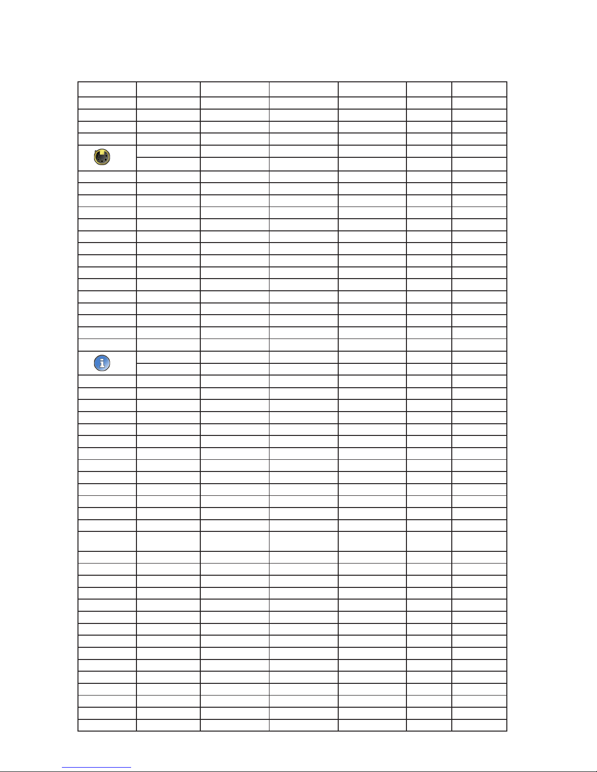
4. Control menu map
Default settings=Bold print
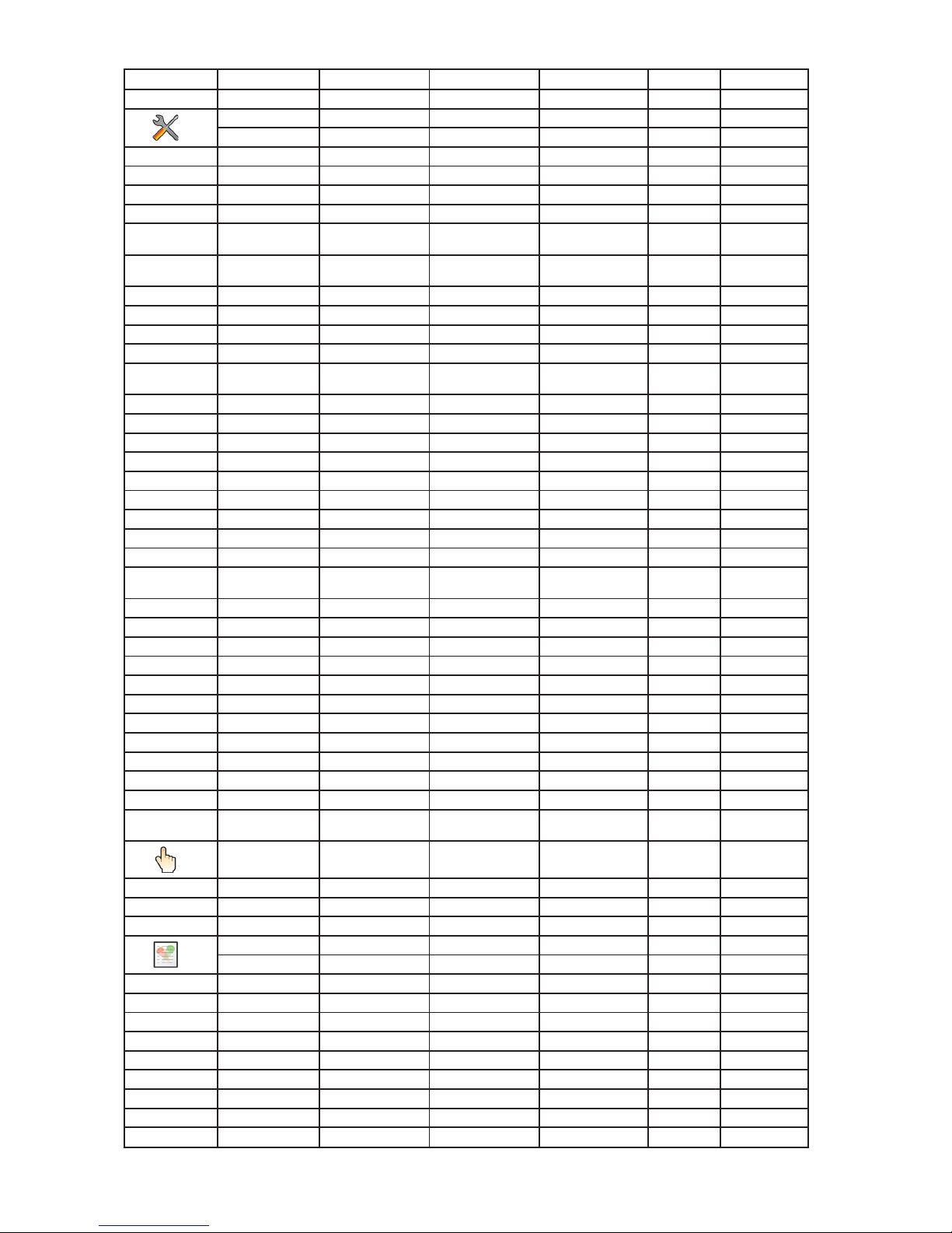
Tab Level 1 Level 2 Level 3 Level 4 Level 5 Level 6
Addressing Settings DMX Address 001-255
DMX Presets Mode 1
:
Mode 5
Ethernet Settings Ethernet Mode Disable
ArtNet
gMAI
gMA2
sACN
Ethernet To DMX On
O
IP Address/NetMask Default IP Address
Custom IP Address
Net Mask
ArtNet Universe 0-255
MANet settings MANet I/IIUniverse 1-256
MANet Session ID 1-32
sACN Settings sACN Universe
sACN Priority
Information Fixture Times Power On Time Total Hours
Resetable Hours
Fixture Temperatures
LEDs Temperature Current
Maximum NonRes.
Maximum Res.
Board temperature Current
Maximum NonRes.
Maximum Res.
Base Temperature Current
Maximum NonRes.
Maximum Res.
DMX Values Red Foreground
:
Zone Eects Speed
Wireless State Signal Quality
Unlink Wireless Adapter
Power Channel
State
Software Versions Display System
Module L1
Module L2
Module L3
Module L4
Product IDs Mac Address
RDM UID
RDM Label
View Logs Fixture Errors
Fixture Status Power On
Power O
Fixture Position
Fixture Temperatures LEDs Temperature
Board Temperature
Base Temperature
Page 14
14
Tab Level 1 Level 2 Level 3 Level 4 Level 5 Level 6
Personality DMX Presets Mode 1
:
Mode 5
View Selected Preset
DMX Input Wired Input
Wireless Input
Wireless In/XLR Out
Microphone Sensitivity
1-10-20
Colour Calibration
Mode
On, O
Colour mixing Mode RGBW,CMY
White Counting On, O
Dimmer Curve Linear
Square Law
Foreground/Background
F.And B..
F+B
F overwrites B.
Init Eect Positions Red Foreground 0-255
:
Zone Eects Speed 0-255
Screen Settings Display Intensity 1-10
Screen Saver Delay O-10min.
Touchscreen Lock O-10min.
Recalibrate Touch-
screen
Display Orientation Normal
Inverted
Auto
Temperature Unit °C,°F
Fan Mode Auto
High
Date & Time Settings
Default Settings
Date & Time Settings
Default Settings
Manual Control Manual Eect Con-
trol
Red Foreground 0-255
:
Zone Eects Speed 0-255
Stand -Alone Test Sequences
MusicTrigger O, On
Preset Playback None
Test
:
Prog. 3
Play Program Play Program 1
Play Program 2
Play Program 3
Edit Program Edit Program 1 Start Step 1-88
End Step 1-88
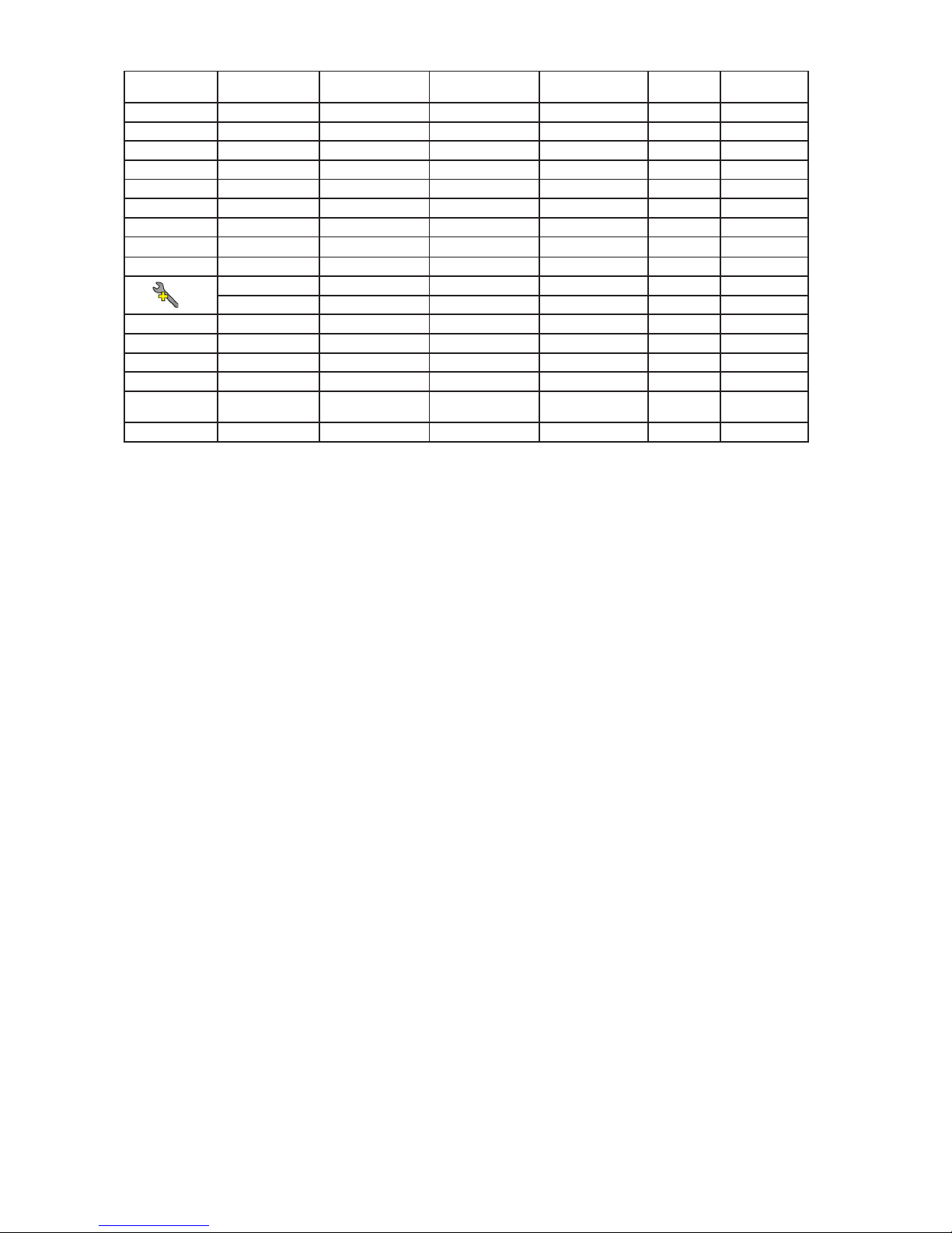
Tab Level 1 Level 2 Level 3 Level 4 Level 5 Level 6
Page 15
15
Edit Program Steps Step 1 Red Fore-
ground
0-255
: :
: Step Time 0-25.5s
: Fade Time 0-25,5s
Step 88 Int. All Zones 0-255
:
Step Time 0-25.5s
Fade Time 0-25,5s
Service Adjust DMX values Red Foreground
:
Zone Eects speed
Calibrations Calibrate Colours Red 0-255
Green 0-255
Blue 0-255
White 0-255
Load Default Calibrations
Update Software
Page 16

16
6. Strobe and Special eects running
6.1 Strobe
Mode 3 and 4
Mode 1 and 2
6.2 Special eects
Rumping
Rump Up
Rump Down
Page 17

17
Rump Up/Down
Lightning
Mode 1, 2, 4
Spikes
For Duration and Rate timing serves the same values as for strobe
Page 18

18
7. Control menu
The Robin ColorStrobe Lite is equipped with the QVGA Robe touch screen with battery backup which
allows to set the xture´s behaviour according to your needs, obtain information on its operation, test its
various parts and lastly program it, if it has to be used in a stand-alone mode.
The xture´s menu can be controlled either by the control buttons or directly by touching the icon.
Control buttons on the front panel:
[ESCAPE] button used to leave the menu without saving changes.
[NEXT] , [PREV] buttons for moving between menu items and symbols, adjusting values.
[ENTER/Display On] button used to enter the selected menu (menu item) and to conrm adjusted value.
If the xture is disconnected from mains, the button switches the touch screen on.
Icons used in the touch screen menu:
- [back arrow] used to move back to the previous screen (menu).
- [up arrow] used to move up on the previous page.
- [down arrow] used to move down on the next page.
- [conrm] used to save adjusted values, to leave menu or to perform desired action.
- [cancel] used to leave menu item without saving changes.
- [conrm+copy] used to save adjusted values and copy them to the next prog. step.
- [warning icon] used to indicate some error which has occurred in the xture.
- [Ethernet] used to indicate Ethernet connected.
- [display turn] used to turn the display by 180°.
- [slider control] used to recall slider system for setting desired value.
- [keyboard control] used to recall keyboard system for setting desired value.
The green icon at the top right corner of the screen indicates the level
of the display battery charging. If the whole icon is green, the battery is
fully charged while the red icon indicates exhausted battery. The battery
charges during xture operation, its charging lasts cca 6 hours.
We recommend that the xture should be in operation at least 7 hours
per week to keep the battery fully charged.
If you switch the xture on and this screen will not appear till 1 minute,
switch the xture o and on again. If the screen lights, the battery is
exhausted. In case the screen still does not light, the battery is faulty.
Page 19

19
The menu page displays icons for each function that you can perform from the touch screen.
After switching the xture on, the touch screen shows the screen with the ROBE logo:
Touch any part of the screen or press the [ENTER/Display On] button to display the initial screen with the current stored DMX address:
Touch the green arrow at the bottom right corner of the screen or press the [ENTER/Display On] button to enter
the " Address" menu.
An item (such as a Tab, menu item, text box, icon) may be selected from a screen by simply touching the item
in the list or by pressing the [NEXT] or [PREV] buttons to scroll through list items. With each press, the next
item is highlighted. Press [ENTER/Display On] to select the highlighted item.
Before rst xture operation, set current date and time in the menu "Date &Time
Setings" (menu path: Personality--> Date &Time Setings).
7.1 Tab " Address"
Settings - Select the menu to set desired xture address setting.
DMX Address - Select the menu to set the DMX start address.
DMX Preset - Use the menu to select desired DMX mode.
Mode 1 - 9 control channels (default)
Mode 2 - 14 control channels
Mode 3 - 18 control channels
Mode 4 - 28 control channels
Mode 5 - 84 control channels
View Selected Preset - Use the menu to display channels included in the selected mode.
Ethernet Settings - The menu allows all needed settings for the Ethernet operation
Ethernet Mode
Disable - The option disables Ethernet operation.
Artnet - Fixture
receives Artnet protocol
gMAI
- Fixture
receives MANet I protocol
gMA2
- Fixture
receives MANet 2 protocol
sACN
- Fixture
receives sACN protocol
Ethernet To DMX - Fixture receives
protocol
from the Ethernet input and sends DMX
data to its DMX output (xture works as an "Ethernet/DMX converter",
next xture can be connected
to its DMX output and you can build a standard DMX chain by connecting another xtures.
Only one xture has to be connected to the Ethernet.
IP Address/Net Mask - Select this menu to set IP address. IP address is the Internet protocol
address.The IP uniquely identies any node (xture) on a network.
There cannot be 2 xtures with the same IP address on the network!
Default IP Address -Preset IP address, you can set up only rst byte of IP address
(2 or 10) e.g. 002.019.052.086.
Page 20

20
Custom IP Address - The option enables to set up all bytes of IP address.
Net Mask - The option enables to set up all bytes of Net Mask.
ArtNet Universe - Use
this item to set a Universe (0-255). The Universe is a single DMX
512 frame
of 512 channels.
MANet Settings - Use this menu to set parameters for MANet operation.
MANet Universe I/II - The value of this item can be set in range 1-256.
MANet Session ID - The value of this item can be set in range 1-32.
sACN Settings - Use this menu to set parameters for sACN operation.
sACN Universe - The value of this item can be set in range 1-32000.
sACN Priority - The value of this item can be set in range 0-255.
7.2 Tab "Information"
Fixture Times - The menu provides readouts of xture operation hours.
Power On Time Hours - Select this menu to read the number of xture operation hours.
Total Hours -
The item shows the total number of the operation hours since the
Robin ColorStrobe Lite
has been fabricated.
Resetable Hours -
The item shows the number of the operation hours that the
Robin ColorStrobe Lite
has been powered on since the counter was last reset.
In order to reset this counter to 0, touch the text box next to the item "Resetable Hours:"
Fixture Temperatures - The menu is used to view temperatures of the xture´s inside.
LEDs Temperature - The menu shows temperatures in the LED module.
Current - A current temperature of the LED module.
Maximum NonRes. - A maximum temperature of the LED module since the xture has
been fabricated.
Maximum Res. - A maximum temperature of the LED module since the counter
was last reset.
In order to reset this counter to 0, touch the text box next to the item "Maximum Res."
Leds Board Temperature - The menu shows temperatures on the LED control PCB.
Current - A current temperature of the LED control PCB.
Maximum NonRes. - A maximum temperature of the LED control PCB since the xture has
been fabricated.
Maximum Res. - A maximum temperature of the LED control PCB since the counter
was last reset.
In order to reset this counter to 0, touch the text box next to the item "Maximum Res."
Base Temperature - The menu shows temperature at the touch screen control module.
Current - A current temperature at the touch screen control module.
Maximum NonRes. - A maximum temperature at the touch screen control module
base since the xture has been fabricated.
Maximum Res. - A maximum temperature at the touch screen control module since
the counter was last reset.
In order to reset this counter to 0, touch the text box next to the item "Maximum Res."
DMX Values - The menu is used to read DMX values of each channel received by the xture.
Wireless State - The menu serves for reading of the wireless operation status (only for Wireless DMX version
of the xture).
Unlink Wireless Adapter - The item serves for unlinking the xture from the transmitter.
Power Channel State - The menu item shows state of the Special functions channel switches.
Product IDs - The menu is used to read the MAC Address ,RDM UID and RDM Label.
Software Version - Select this item to read the software version of the xture modules:
Display System - a display processor.
Module L - a LED module processor.
Page 21

21
View Logs - Use this menu to read xture´s data which have been recorded during xture operation. This
colected data allows easier troubleshooting.
Fixture Errors - Use this menu to read xture errors which have occured during xture operation.
Fixture Status - Recorded following actions: Power On, Power O.
Fixture Position - Recorded installation positions of the xture:
Fixture Temperatures - Recorded temperatures which have exceeded dened levels.
7.3 Tab "Personality"
User mode - The Robin ColorStrobe Lite allows you to recall up to 3 user settings. After switching the xture on
for the rst time, the User A settings is active. Now all changes made in the “Personality” menu , ”Addressing”
menu and the “Music Trigger“ and “ Preset Playback“ items from the “Stand-alone” menu are saved to the
User A settings. If you now select the User B settings, from this moment the changes made in these menus will
be saved to the User B settings. After switching the xture o and on, the User B setting is active. In this way
you may use the 3 xture operating behaviours.
User A Settings - the function recalls the user A settings.
User B Settings - the function recalls the user B settings.
User C Settings - the function recalls the user C settings.
DMX Preset - Use the menu to select desired DMX mode.
Mode 1 - 9 control channels (default)
Mode 2 - 14 control channels
Mode 3 - 18 control channels
Mode 4 - 28 control channels
Mode 5 - 84 control channels
View Selected Preset - Use the menu to display channels included in the selected mode.
DMX Input- Use the menu to select mode of receiving DMX signal.
Wired Input - DMX signal is received by means of the standard DMX cable.
Wireless - DMX signal is received by means of the inbuilt wireless module.
Wireless In/XLR Out- the xture receives wireless DMX and sends the signal to its wired DMX output.
The xture behaves as " Wireless/Wired" adapter.
Microphone Sensitivity - Enter the menu if you want to adjust the microphone sensitivity from 1 (max.) to 20
(min.).
Colour Calibration Mode - If the function is on, the white output from the xture (and also mixed colours)
is more uniform. Each colour is corrected according to the values set in the menu "Calibrations" (Service->
Calibrations-> Calibrate Colours).
Colour Mixing Mode - This item allows switching into RGBW or CMY mode. In the CMY mode, the white(8bit)/
white (16) bit channels are not active.
White Counting - If this function is On, the white LEDs light when a white colour is mixed. The light intensity of
the white LEDs is in a proportion to the intensity of the rest of LEDs (red, Green, blue) and improves the white
output of the xture. If you want lit with white LEDs only, this function has to be set o.
Dimmer Curve - Use this menu item to select linear or square law dimmer curve.
Page 22

22
Foreground/Background - The function allows to set desired relation between colours of foreground and
background.
Init Eect Positions - Use the menu to set all eects to the desired positions at which they will stay after
switching the xture on without DMX signal connected.
Screen Settings - Use this menu to change the touch screen settings.
Display Intensity - The item allows to control the intensity of the screen (1-min., 10-max.).
Screen saver Delay - The item allows you to keep the screen on or to turn it o automatically after 1-10
minutes after last touch (or pressing any button on the control panel).
Touchscreen Lock - The item allows you to lock the screen after last touch (or pressing any button on the
control panel). The time delay can be set in range of 1-10 minutes.To unlock the screen, press the
[ENTER/Display On] button.
Recalibrate Touchscreen - The item starts calibration of the touchscreen. Follow the instructions on
the screen.
Display Orientation - The menu allows to change display orientation.
Normal - Standard display orientation if the xture is placed horizontally (e.g. on the ground).
Inverted - Inverted orientation (needed if the xture is hanging on the truss).
Auto - The option activates a gravitation sensor for automatic screen orientation.
Note: Auto option is set as default. You change the display orientation by touching the icon on the display,
an the option set in the "Display Orientation" menu is temporarily overriden.
Temperature unit - Use the menu item to change temperature unit from °C to °F.
Fan Mode - Use the menu to set the xture fans to max. fan power mode ("High") or to auto- control mode
("Auto").
Date & Time Settings - Use this menu to set current date and time for the xture log system (menu "View
Logs"). Set this menu item before rst xture operation.
Default Settings - The menu item allows to set all xture parameters to the default (factory) values.
7.4 Tab "Manual Control"
Manual Eect control - Use the menu to control all xture channels by means of the control panel.
7.5 Tab "Stand-alone"
Test Sequences -Use the menu item to run a test/demo sequences without an external controller, which will
show you some possibilities of using Robin ColorStrobe Lite.
Music Trigger - Use the item to activate the sound control of the running program via the built-in microphone.
Preset Playback - This menu allows you to select the program which will be played in a loop after switching
the xture on (the option is commonly used in a stand-alone operation without an external controller).
None - The option disables “Presetting playback” function.
Test - The option starts the test sequences.
Prog. 1 - The option starts user program No. 1.
Prog. 2 - The option starts user program No. 2.
Prog. 3 - The option starts user program No. 3.
Play program - Use the menu to run desired program in a loop.
Play Program 1 - The option starts user program No.1.
Play Program 2 - The option starts user program No. 2.
Play Program 3 - The option starts user program No. 3.
Page 23

23
Edit Program - Use the menu to create or to edit desired program. The Robin ColorStrobe Lite oers 3 free
programs, each up to 88 steps.
Edit Program 1 - The option allows to edit user program No.1.
Edit Program 2 - The option allows to edit user program No.2.
Edit Program 3 - The option allows to edit user program No.3
To edit program:
1. Touch the item which you want to edit (“Edit Program 1” - “Edit Program 3”).
2. Touch the item "Edit Program Steps".
3. Touch the item "Step 1".
4 From the list of eects touch desired eect and set its value. Browse throw the list by touching the [up arrow]
and [down arrow] and set all desired eects.
An item "Step Time" (value of 0-25.5 sec.) is the time during which eects last in the current step
5. Save adjusted eects to the current step by touching the [conrm] or save and copy them to the following
step by touching the [conrm+copy]. By touching the text box "Preview" next to the current program step you
can view created scene.
6. Repeat the steps 4 and 5 for next program steps.
7. After editing desired program steps, adjust the length of the program by touching the text boxes "Start Step"
and "End Step".
Meaning of the icons used in the "Edit Program" menu:
- moves down on the next page - saves adjusted values and leaves menu
- moves up on the previous page - saves values to the current step and copy them to the
following prog. step
- leaves menu without saving values
7.6 Tab "Service"
Adjust DMX Values - The menu allows you to set all eects to desired positions before colour calibration of
the xture.
Calibrations
Calibrate Colours - The menu serves for adjusting of LED saturations to achieve colour temperature of
5600K for white output.
Red - a red LEDs saturation adjustment
Green - a green LEDs saturation adjusment
Blue - a blue LEDs saturation adjustment
White - a white LEDs saturation adjustment
Calibration of the white 5600K via the control board
1. Disconnect DMX controller from the xture. Set the menu item "Colour Calibration Mode" to On
(tab Personality-> Colour Calibration Mode-> On) and go to the "Adjust DMX Values" menu
(tab Service-> Adjust DMX Values).
2. Set "Intensity foreground", "Duration" and "Rate" at 255 DMX and "Virtual colour wheel" at 10 DMX (white
5600K).
3. Point the centre of the light beam on the lux meter (e.g. Minolta CL-200A Chroma meter) which is placed
at min. distance of 2.5m from the xture
4. Enter the menu "Calibrate Colours".
5. By means of the Red, green, Blue and White items adjust the 5600K colour temperature as exactly as
possible (∆u´v´= 0).
7. After adjusting 5600K colour temperature, touch the [conrm] to save all adjusted values.
Note: you can also use DMX controler for this calibration, calibration protocol is the following:
Page 24

24
Eect Mode1
Red - red saturation channel 10
Green- green saturation channel 11
Blue - blue saturation channel 12
White - white saturation channel 13
Load Default Calibrations - The item loads default (factory) calibration values.
Updating software - The menu item allows you to update software in the xture via either serial or USB port
of PC.
The following are required in order to update software:
- PC running Windows 95/98/2000/XP/7/8 or Linux
- DMX Software Uploader
- Flash cable RS232/DMX No.13050624 (if you want to use a serial port of PC)
- Robe Universal Interface (if you want to use an USB port of PC)
Note: Software update should execute a qualied person. If you lack qualication, do not attempt the
update yourself and ask for help your ROBE distributor.
DMX address, IP address, programs 1-3 and all items in the menu "Personality" will be set to their default
(factory) values.
To update software in the xture:
I. Installation of the DMX Software Uploader.
1. DMX Software Uploader program is available from the ROBE web site at WWW.robe.cz.
2. Make a new directory ( e.g. Robe_Uploader) on your hard disk and download the software to it.
3. Unpack the seftware.
II.Fixture software updating.
1.Determine which of your ports is available on your PC and connect it:
- with the DMX input of the xture if you using the ash cable RS232/DMX
- with the DMX output of the Robe Universal Interface if you using the USB cable.
Disconnect the xture from the other xtures in a DMX chain. Turn both the computer and
the xture on. Make sure the lamp is switched o (only if the xture involves a lamp).
2. Switch the xture to the updating mode by touching the "Updating Software " item
Note: If you do not want to continue in software update, you have to switch o and on the xture
to escape from this menu.
We recommend to cancel all running programs before starting the Software Uploader.
3. Run the Software Uploader program. Select desired COM and then click on the Connect button.
(Select COM if the serial port is used or Robe Universal Interface if the USB port is used).
If the connection is OK, click on the “Start Uploading button“ to start uploading. It will take several
minutes to perform software update.
If the option "Incremental Update" is not checked, all processors will be updated (including
processors with the same software version).
If you wish to update only later versions of processors, check the “Incremental Update box“.
Avoid interrupting the process. Update status is being displayed in the Info Box window.
When the update is nished, the line with the text “The xture is successfully updated“ will appear in
this window and the xture will reset with the new software.
Note: In the case of an interruption of the upload process (e.g. power cut), the xture keeps the updating mode
and you have to repeat the software update again.
Page 25

25
8. RDM
This xture supports RDM operation. RDM (Remote Device Management) is a bi-directional communications
protocol for use in DMX512 control systems, it is the new open standard for DMX512 device conguration and
status monitoring.
The RDM protocol allows data packets to be inserted into a DMX512 data stream without adversely aecting
existing non-RDM equipment. By using a special „Start Code,“ and by complying with the timing specications
for DMX512, the RDM protocol allows a console or dedicated RDM controller to send commands to and receive
messages from specic moving lights.
RDM allows explicit commands to be sent to a device and responses to be received from it.
The list of commands for the Robin ColorStrobe Lite is the following.
Parameter ID Discovery command SET command GET command
DISC_UNIQUE_BRANCH *
DISC_MUTE *
DISC_UN_MUTE *
DEVICE_INFO *
SUPPORTED_PARAMETERS *
SOFTWARE_VERSION_LABEL *
DMX_START_ADDRESS * *
IDENTIFY_DEVICE * *
DEVICE_MODEL_DESCRIPTION *
MANUFACTURER_LABEL *
DEVICE_LABEL * *
SENSOR_DEFINITION *
SENSOR_VALUE *
DISPLAY_INVERT * *
DISPLAY_LEVEL * *
PAN_INVERT * *
TILT_INVERT * *
DEVICE_RESET *
DMX_PERSONALITY * *
DMX_PERSONALITY_DESCRIPTION *
STATUS_MESSAGES *
STATUS_ID_DESCRIPTION *
DEVICE_HOURS
*
PARAMETER_DESCRIPTION *
ROBE_DMX_INPUT * *
ROBE_WIRELESS_UNLINK *
9. Wireless DMX operation
The wireless DMX version of the Robin ColorStrobe Lite is equipped with the Lumen Radio CRMX module
and antenna for receiving DMX signal. CRMX module operates on the 2.4 GHz band.
The item " Wireless " from the menu "DMX Input" allows you to activate receiving of wireless DMX (Personality--> DMX Input -->Wireless.).
To link the xture with DMX transmitter.
The xture can be only linked with the transmitter by running the link procedure at DMX transmitter .
After linking , the level of DMX signal ( 0-100 %) is displayed in the menu item “Wireless State“ (Information
-->Wireless State).
To unlink the xture from DMX transmitter.
The xture can be unlinked from receiver via the menu item “ Unlink Wireless Adapter“ (Information--> Wireless
State --> Unlink Wireless Adapter.).
Page 26

26
10. Error and information messages
Occurred errors during xture operation are signalled by the yellow warning icon at the bottom line of the screen:
Touch the warning icon or press the [ESCAPE] button to display error messages.
List of error and information messages:
Temp. Sensor Error
The message informs you that the communication between the head temperature sensor and the main processor failed.
LED Zone 1 Short Error
The message informs you that short circuit has occured on the PCB of LED zone 1.
LED Zone 2 Short Error
The message informs you that short circuit has occured on the PCB of LED zone 2.
LED Zone 3 Short Error
The message informs you that short circuit has occured on the PCB of LED zone 3.
LED Zone 4 Short Error
The message informs you that short circuit has occured on the PCB of LED zone 4.
LED Zone 5 Short Error
The message informs you that short circuit has occured on the PCB of LED zone 5.
LED Zone 6 Short Error
The message informs you that short circuit has occured on the PCB of LED zone 6.
LED Zone 7 Short Error
The message informs you that short circuit has occured on the PCB of LED zone 7.
LED Zone 8 Short Error
The message informs you that short circuit has occured on the PCB of LED zone 8.
LED Zone 9 Short Error
The message informs you that short circuit has occured on the PCB of LED zone 9.
LED Zone 10 Short Error
The message informs you that short circuit has occured on the PCB of LED zone 10.
LED Zone 11 Short Error
The message informs you that short circuit has occured on the PCB of LED zone 11.
LED Zone 12 Short Error
The message informs you that short circuit has occured on the PCB of LED zone 12.
Internal Error 1
Communication error between PCBs (error or noise was detected on communication wires)
Internal Error 2
Ballast communication error (some PCB has failed or is disconnected (this PCB will show as N/A in menu -->
Information --> Software versions) or error/noise was detected on communication wires)
Page 27

27
11. Technical Specications
Electrical
Power supply:.........................electronic auto-ranging
Input voltage range:............... 100-240V, 50/60Hz
Fuse:.......................................T15 A
Max. power consumption:.......1300 W @230V (power factor=0,99, I=5.7A)
Optic
Light source: 120 x 15W RGBW multichips
4 or 12 LED zones with individual control of each
Typical Lumen Maintenance: 70% @ 40,000 hours
LED life expectancy: 40.000 hours
Virtual colour wheel
237 colours including whites (2700K, 3200K, 4200K, 5600K and 8000K)
Halogen lamp eect at whites 2700K and 3200K
Rainbow eect with in both directions with variable speed
Zone eectsl
Zone eects in both directions with variable speed
Strobe
Strobe eect with variable speed
Pulses adjustment: frequency, duration, intensity
Special eects: rump up, rump down, rump up/down, random, lighting, spikes
Control
Graphic touch screen for xture setting and addressing
Gravitation sensor for auto screen positioning
Battery backup of the touch screen
Readout xture usage, receiving DMX values, temperatures, etc
Built-in analyzer for easy fault nding, error messages
Built-in demo sequences
Stand-alone operation
3 user editable programs, each up to 88 steps
Supported protocols: USITT DMX 512, RDM, ArtNet, MANet, MANet2, sACN
Support of RDM (Remote Device Management)
5 DMX modes (9, 14, 18, 28,84 control channels)
Optional Wireless DMX/RDM module
Compliance with USITT DMX-512 (1986 & 1990) and 512-A
Full DMX delity and frame integrity
Auto sensing of DMX frame rate and frame size
<5ms DMX latency
Operational frequency range of 2402-2480 MHz
Producer: LumenRadio
Connection
DMX data in/out: Locking 5-pin XLR
Ethernet: RJ45
Power: Neutrik NAC3MPX
Rigging
via U-bracket
Page 28

28
Temperatures
Maximum ambient temperature: 45°C
Maximum housing temperature : 90° C
Minimum distances
Min. distance from ammable surfaces: 0.5 m
Min. distance to lighted object: 1m
Total heat dissipation
4260 BTU/h (calculated)
Weight (net):
13.4 kg
Dimensions (mm)
Protection factor
IP 2X
Accessories
1 x Mounting bracket Omega CL assembled (P/N 99010420)
Optional accessories
(P/N 10 980 276) Floor stands for Robin Strobe Lite/Colour Strobe Lite
(P/N 10 980 262) Bandoor for Robin Strobe/ColourStrobe/Strobe Lite/ColorStrobe Lite
(P/N 10 980 263) Frame Adaptor for Robin Strobe/ColourStrobe/Strobe Lite/ColorStrobe Lite
(P/N 10 980 264) Gel Frame for Robin Strobe/ColourStrobe/Strobe Lite/ColorStrobe Lite
(P/N 10 980 033) Omega Adaptor CL-regular 2 pcs
(P/N 17 030 386) Doughty Trigger Clamp
(P/N 99 011 963) Safety wire 35 kg
(P/N 13 052 276) Mains Cable PowerCon TRUE1 In/open ended, EU 2m, outdoor
(P/N 13 052 277) Mains Cable PowerCon TRUE1 In/open ended, US 2m, outdoor
(P/N 13 052 405) Mains Cable powerCON TRUE1 In/Schuko, 2m, Indoor
(P/N 13 052 406) Mains Cable powerCON TRUE1 In/US, 2m, Indoor
(P/N 13 052 445) Mains Cable powerCON TRUE1 In/CEE 16A, 2m, Indoor
(P/N 13 052 407) Mains Cable powerCON TRUE1 In/open ended, 2m, Indoor
Page 29

29
Photometric chart
12. Maintenance and cleaning
DANGER !
Disconnect from the mains and allow to cool completely before starting any
cleaning or maintenance work
The front transparent cover will require monthly cleaning as smoke uid tends to build up residues, reducing
the light output very quickly. For cleaning use a wet clout and a vacuum-cleaner or air-jet. Do not use solvents
or any other aggressive cleaning uid.
The interior of the xture including fans should be cleaned annually (or more often according operating conditions) using a vacuum-cleaner and a soft brush. A qualied electrician should service and clean the interior of
the xture as disconnecting and connectinng electrical cables is required.
Should you need any spare parts, please use genuine parts.
More complicated maintenance and service operations are only to be carried out by authorized distributors.
Page 30

30
To get access to the xture´s inside
1. Unscrew three screws (1) along both sides of the rear cover (2).
2. Disconnect cables between rear cover and inside of the xture (power, display, DMX).
3. Unscrew two screws (3) at each side of the chassis with power supply (4) and pull the chassis out
with care.
4. Now you can clear inside of the xture including fans (5).
12.1 Replacing fuse
Only replace the fuse by a fuse of the same type and rating.
Before replacing the fuse, unplug mains lead!
1) Remove the fuse holder on the rear panel of the base with a tting screwdriver from the housing
(anti-clockwise).
2) Remove the old fuse from the fuse holder.
3) Install the new fuse in the fuse holder (only the same type and rating).
4) Replace the fuse holder in the housing and x it.
12.2 Disposing of the product
To preserve the environment please dispose or recycle this product at the end of its life according to the local
regulations and codes.
January 23, 2018
Copyright © 2016-2018 Robe Lighting - All rights reserved
Specicationsaresubjecttochangewithoutnotice.
MadeinROBELightings.r.o.,Palackého416,75701ValašskéMeziříčí,CzechRepublic
Page 31

DMX protocol
Version: 1.0
1 2 3 4 5
Robin ColorStrobe - DMX protocol
Mode/channel
DMX
value
Function
Type of
control
111**
Red/Cyan foreground (8 bit)- all zones
0 - 255 Red orCyan colour saturation control - coarse (0-100%)
proportional
* 2 * * *
Red/Cyan foreground (16bit)- all zones
0 - 255 Red or Cyan colour saturation control - fine
proportional
2 3 2 * *
Green/Magenta foreground (8-bit) - all zones
0 - 255 Green or Magenta colour saturation control - coarse (0-100%)
proportional
* 4 * * *
Green/Magenta foreground (16bit) - all zones
0 - 255
Green or Magenta colour saturation control - fine
proportional
3 5 3 * *
Blue/Yellow foreground (8 bit) - all zones
0 - 255 Blue or Yellow colour saturation control - coarse (0-100%)
proportional
* 6 * * *
Blue/Yellow foreground (16bit) -all zones
0 - 255 Blue or Yellow colour saturation control - fine
proportional
4 7 4 * *
White foreground (8 bit) - all zones
0-255
White colour saturation control - coarse (0-100%) -RGBW mode only
proportional
0-255
White colour saturation control - coarse (0-100%) -RGBW mode only
proportional
* 8 * * *
White foreground (16 bit) - all zones
0 - 255 White colour saturation control - fine (RGBW mode only)
proportional
5 9 5 * *
CTC
0 No function
step
1-255 Col. temperature correction from 8000K to 2700K
proportional
6 10 6 * *
Virtual colour wheel
0
No function
step
1-2 White 2700 K
step
3 White 2700 K (Halogen lamp mode)*
step
4-5 White 3200 K
step
6 White 3200 K (Halogen lamp mode)*
step
7-9 White 4200 K
step
10-12 White 5600 K
step
13-15 White 8000 K
step
16 Blue (Blue=full, Red+Green+White=0)
step
17-55 Red=0, Green->up,Blue =full, White=0
proportional
56 Light Blue (Red=0, Green=full, Blue =full, White=0)
step
57 - 95 Red=0, Green=full, Blue->down, White=0
proportional
96 Green (Red=0, Green=full, Blue =0, White=0)
step
97 – 134
Red->up, Green=full, Blue=0, White=0
proportional
135 Yellow (Red=full, Green=full, Blue=0, White=0)
step
136 - 174 Red=full, Green->down, Blue=0, White=0
proportional
175 Red(Red=full, Green=0, Blue=0, White=0)
step
176 -214 Red=full, Green=0, Blue->up, White=0
proportional
215 Magenta (Red=full, Green=0, Blue=full, White=0)
step
216 - 246 Red -> down, Green=0, Blue=full, White=0
proportional
247
Blue (Red=0, Green=0, Blue=full, White=0)
step
248-251 Rainbow effect (with fade time)from slow-> fast
proportional
252-255 Rainbow effect(without fade time) from slow-> fast
proportional
7 11 7 * *
Intensity foreground (8bit)-all zones
0-255 Coarse intensity from min. to max.
proportional
Page 1
Page 32

DMX protocol
1 2 3 4 5
Mode/channel
DMX
value
Function
Type of
control
* 12 * * *
Intensity foreground (16bit)-all zones
0-255 Fine intensity from min. to max.
proportional
8 13 8 * *
Duration
0-255 Light time duration from min. —>max.
step
9149**
Rate
0-5 No flash
step
6-255 Flash frequency from min. —>max
step
Note: Duration time<Rate: flashing
Duration time>= Rate: Light continuously On
* * 10 * *
Special effects
0-1 No function
step
2-5
Permanent lightening
step
6-42
Ramp up
(use channels Duration and Rate for control)
step
43-85
Ramp down
(use channels Duration and Rate for control)
step
86-128
Ramp up/down
(use channels Duration and Rate for control)
step
129-171
Random strobe
(use channel Rate for control)
step
172-214
Lightning
(use channel Rate for control)
step
215-255
Spikes
(use channels Duration and Rate for control)
step
215-255
Spikes
(use channels Duration and Rate for control)
step
* * 11 * *
Special Functions
0 -19 Reserved
To activate following functions , stop in DMX value for at least 3
sec. Corresponding menu items are temporarily overrided.
20-24
Graphic display On
step
25-29
Graphic display Off
step
25-29
Graphic display Off
step
30-34
RGBW colour mixing mode
step
35-39
CMY colour mixing mode
step
40-44
Colour calibration On
step
45-49
Colour calibration Off
step
50-54
Foreground overwrites Background
step
55-59
Foreground + Background
step
60-64
Foreground and Background - standard (default) behaviour
step
65-69
Fans mode: Auto
step
70-74
Fans mode: high
step
75-79 White counting On
step
80-84 White counting Off
step
85-89
Dimmer curve: linear
step
90-94
Dimmer curve: square law
step
95-255
Reserved
* * 12 * *
Red/Cyan Background (8 bit)- all zones
0 - 255 Red or Cyan colour saturation control - coarse (0-100%)
proportional
* * 13 * *
Green/Magenta Background (8 bit) - all zones
0 - 255 Green or Magenta colour saturation control - coarse (0-100%)
proportional
* * 14 * *
Blue/Yellow Background (8 bit) - all zones
0 - 255
Blue or Yellow colour saturation control - coarse (0-100%)
proportional
0 - 255
Blue or Yellow colour saturation control - coarse (0-100%)
proportional
* * 15 * *
White Background (8 bit) - all zones
0-255
White colour saturation control - coarse (0-100%)-only RGBW mode
proportional
* * 16 * *
Intensity Background (8bit)-all zones
0-255 Coarse intensity from min. to max.
proportional
Page 2
Page 33

DMX protocol
1 2 3 4 5
Mode/channel
DMX
value
Function
Type of
control
* * 17 * *
Zone Effects
0-2
No function
step
3-4 Effect 1
step
5-6 Effect 2
step
7-8
Effect 3
step
9-10 Effect 4
step
11-12 Effect 5
step
13-14 Effect 6
step
15-16 Effect 7
step
17-18 Effect 8
step
19-20 Effect 9
step
21-22
Effect 10
step
23-24 Effect 11
step
25-26 Effect 12
step
27-28 Effect 13
step
29-30 Effect 14
step
31-32 Effect 15
step
33-34
Effect 16
step
33-34
Effect 16
step
35-36 Effect 17
step
37-38 Effect 18
step
39-40 Effect 19
step
41-42 Effect 20
step
43-44 Effect 21
step
45-46 Effect 22
step
47-48
Effect 23
step
49-50 Effect 24
step
51-52 Effect 25
step
53-255 Reserved
step
* * 18 * * Zone Effects Speed
0-63 Speed from min. —>max. without fade time
proportional
64-127 Speed from max. —>min. without fade time (op. direction)
proportional
128-191 Speed from min. —>max. with fade time
proportional
192-255 Speed from max. —>min. with fade time (op. direction)
proportional
* * * 1 1 Red intensity (8bit)-zone 1
0-255 Coarse red intensity from 0% to 100%
proportional
* * * 2 2 Green intensity (8bit)-zone 1
0-255 Coarse green intensity from 0% to 100%
proportional
***33
Blue intensity (8bit)-zone 1
0-255 Coarse blue intensity from 0% to 100%
proportional
* * * 4 4 White intensity (8bit)-zone 1
0-255 Coarse white intensity from 0% to 100%
proportional
* * * 5 5 Intensity (8bit)-zone 1
0-255 Coarse intensity from 0% to 100%
proportional
* * * 6 6 Duration - zone 1
0-255
Light time duration from min. —>max.
step
* * * 7 7 Rate - zone 1
0-5 No flash
step
6-255 Flash frequency from min. —>max
step
* * * 8 8 Red intensity (8bit)-zone 2
Page 3
Page 34

DMX protocol
1 2 3 4 5
Mode/channel
DMX
value
Function
Type of
control
0-255 Coarse red intensity from 0% to 100%
proportional
* * * 9 9 Green intensity (8bit)-zone 2
0-255 Coarse green intensity from 0% to 100%
proportional
* * * 10 10 Blue intensity (8bit)-zone 2
0-255
Coarse blue intensity from 0% to 100%
proportional
* * * 11 11 White intensity (8bit)-zone 2
0-255 Coarse white intensity from 0% to 100%
proportional
* * * 12 12 Intensity (8bit)-zone 2
0-255 Coarse intensity from 0% to 100%
proportional
* * * 13 13 Duration - zone 2
0-255 Light time duration from min. —>max.
step
***1414
Rate - zone 2
0-5 No flash
step
6-255 Flash frequency from min. —>max
step
* * * 15 15 Red intensity (8bit)-zone 3
0-255 Coarse red intensity from 0% to 100%
proportional
* * * 16 16 Green intensity (8bit)-zone 3
0-255
Coarse green intensity from 0% to 100%
proportional
0-255
Coarse green intensity from 0% to 100%
proportional
* * * 17 17 Blue intensity (8bit)-zone 3
0-255 Coarse blue intensity from 0% to 100%
proportional
* * * 18 18 White intensity (8bit)-zone 3
0-255 Coarse white intensity from 0% to 100%
proportional
* * * 19 19 Intensity (8bit)-zone 3
0-255 Coarse intensity from 0% to 100%
proportional
***2020
Duration - zone 3
0-255 Light time duration from min. —>max.
step
* * * 21 21 Rate - zone 3
0-5 No flash
step
6-255 Flash frequency from min. —>max
step
* * * 22 22 Red intensity (8bit)-zone 4
0-255 Coarse red intensity from 0% to 100%
proportional
* * * 23 23 Green intensity (8bit)-zone 4
0-255 Coarse green intensity from 0% to 100%
proportional
* * * 24 24 Blue intensity (8bit)-zone 4
0-255 Coarse blue intensity from 0% to 100%
proportional
* * * 25 25 White intensity (8bit)-zone 4
0-255 Coarse white intensity from 0% to 100%
proportional
***2626
Intensity (8bit)-zone 4
0-255 Coarse intensity from 0% to 100%
proportional
* * * 27 27 Duration - zone 4
0-255 Light time duration from min. —>max.
step
* * * 28 28 Rate - zone 4
0-5 No flash
step
6-255 Flash frequency from min. —>max
step
****29
Red intensity (8bit)-zone 5
0-255 Coarse red intensity from 0% to 100%
proportional
* * * * 30 Green intensity (8bit)-zone 5
0-255 Coarse green intensity from 0% to 100%
proportional
* * * * 31 Blue intensity (8bit)-zone 5
Page 4
Page 35

DMX protocol
1 2 3 4 5
Mode/channel
DMX
value
Function
Type of
control
0-255 Coarse blue intensity from 0% to 100%
proportional
* * * * 32 White intensity (8bit)-zone 5
0-255 Coarse white intensity from 0% to 100%
proportional
* * * * 33 Intensity (8bit)-zone 5
0-255
Coarse intensity from 0% to 100%
proportional
* * * * 34 Duration - zone 5
0-255 Light time duration from min. —>max.
step
* * * * 35 Rate - zone 5
0-5 No flash
step
6-255 Flash frequency from min. —>max
step
* * * * 36 Red intensity (8bit)-zone 6
0-255
Coarse red intensity from 0% to 100%
proportional
* * * * 37 Green intensity (8bit)-zone 6
0-255 Coarse green intensity from 0% to 100%
proportional
* * * * 38 Blue intensity (8bit)-zone 6
0-255 Coarse blue intensity from 0% to 100%
proportional
* * * * 39 White intensity (8bit)-zone 6
0-255
Coarse white intensity from 0% to 100%
proportional
0-255
Coarse white intensity from 0% to 100%
proportional
* * * * 40 Intensity (8bit)-zone 6
0-255 Coarse intensity from 0% to 100%
proportional
* * * * 41 Duration - zone 6
0-255 Light time duration from min. —>max.
step
* * * * 42 Rate - zone 6
0-5 No flash
step
6-255
Flash frequency from min. —>max
step
* * * * 43 Red intensity (8bit)-zone 7
0-255 Coarse red intensity from 0% to 100%
proportional
* * * * 44 Green intensity (8bit)-zone 7
0-255 Coarse green intensity from 0% to 100%
proportional
* * * * 45 Blue intensity (8bit)-zone 7
0-255 Coarse blue intensity from 0% to 100%
proportional
* * * * 46 White intensity (8bit)-zone 7
0-255 Coarse white intensity from 0% to 100%
proportional
* * * * 47 Intensity (8bit)-zone 7
0-255 Coarse intensity from 0% to 100%
proportional
* * * * 48 Duration - zone 7
0-255 Light time duration from min. —>max.
step
****49
Rate - zone 7
0-5 No flash
step
6-255 Flash frequency from min. —>max
step
* * * * 50 Red intensity (8bit)-zone 8
0-255 Coarse red intensity from 0% to 100%
proportional
* * * * 51 Green intensity (8bit)-zone 8
0-255 Coarse green intensity from 0% to 100%
proportional
****52
Blue intensity (8bit)-zone 8
0-255 Coarse blue intensity from 0% to 100%
proportional
* * * * 53 White intensity (8bit)-zone 8
0-255 Coarse white intensity from 0% to 100%
proportional
* * * * 54 Intensity (8bit)-zone 8
Page 5
Page 36

DMX protocol
1 2 3 4 5
Mode/channel
DMX
value
Function
Type of
control
0-255 Coarse intensity from 0% to 100%
proportional
* * * * 55 Duration - zone 8
0-255 Light time duration from min. —>max.
step
* * * * 56 Rate - zone 8
0-5
No flash
step
6-255 Flash frequency from min. —>max
step
* * * * 57 Red intensity (8bit)-zone 9
0-255 Coarse red intensity from 0% to 100%
proportional
* * * * 58 Green intensity (8bit)-zone 9
0-255 Coarse green intensity from 0% to 100%
proportional
* * * * 59 Blue intensity (8bit)-zone 9
0-255
Coarse blue intensity from 0% to 100%
proportional
* * * * 60 White intensity (8bit)-zone 9
0-255 Coarse white intensity from 0% to 100%
proportional
* * * * 61 Intensity (8bit)-zone 9
0-255 Coarse intensity from 0% to 100%
proportional
* * * * 62 Duration - zone 9
0-255
Light time duration from min. —>max.
step
0-255
Light time duration from min. —>max.
step
* * * * 63 Rate - zone 9
0-5 No flash
step
6-255 Flash frequency from min. —>max
step
* * * * 64 Red intensity (8bit)-zone 10
0-255 Coarse red intensity from 0% to 100%
proportional
* * * * 65 Green intensity (8bit)-zone 10
0-255
Coarse green intensity from 0% to 100%
proportional
* * * * 66 Blue intensity (8bit)-zone 10
0-255 Coarse blue intensity from 0% to 100%
proportional
* * * * 67 White intensity (8bit)-zone 10
0-255 Coarse white intensity from 0% to 100%
proportional
* * * * 68 Intensity (8bit)-zone 10
0-255 Coarse intensity from 0% to 100%
proportional
* * * * 69 Duration - zone 10
0-255 Light time duration from min. —>max.
step
* * * * 70 Rate - zone 10
0-5 No flash
step
6-255 Flash frequency from min. —>max
step
* * * * 71 Red intensity (8bit)-zone 11
0-255
Coarse red intensity from 0% to 100%
proportional
* * * * 72 Green intensity (8bit)-zone 11
0-255 Coarse green intensity from 0% to 100%
proportional
* * * * 73 Blue intensity (8bit)-zone 11
0-255 Coarse blue intensity from 0% to 100%
proportional
* * * * 74 White intensity (8bit)-zone 11
0-255 Coarse white intensity from 0% to 100%
proportional
****75
Intensity (8bit)-zone 11
0-255 Coarse intensity from 0% to 100%
proportional
* * * * 76 Duration - zone 11
0-255 Light time duration from min. —>max.
step
* * * * 77 Rate - zone 11
Page 6
Page 37

DMX protocol
1 2 3 4 5
Mode/channel
DMX
value
Function
Type of
control
0-5 No flash
step
6-255 Flash frequency from min. —>max
step
* * * * 78 Red intensity (8bit)-zone 12
0-255 Coarse red intensity from 0% to 100%
proportional
****79
Green intensity (8bit)-zone 12
0-255 Coarse green intensity from 0% to 100%
proportional
* * * * 80 Blue intensity (8bit)-zone 12
0-255 Coarse blue intensity from 0% to 100%
proportional
* * * * 81 White intensity (8bit)-zone 12
0-255 Coarse white intensity from 0% to 100%
proportional
* * * * 82 Intensity (8bit)-zone 12
0-255
Coarse intensity from 0% to 100%
proportional
* * * * 83 Duration - zone 12
0-255 Light time duration from min. —>max.
step
* * * * 84 Rate - zone 12
0-5 No flash
step
6-255 Flash frequency from min. —>max
step
* In the Halogen lamp mode the Dimmer channel imitates behaviour of the halogen lamp during dimming
Order of zones (front view) :
Mode 1,2,3
Mode 4
Mode 5
Page 7
Page 38

Strobe Duration
50 and 60 Hz 50Hz 60Hz 50Hz 60Hz 50Hz 60Hz
[ms] [ms] [ms] [Hz] [Hz] [ms] [ms]
0
13,31
x x x x 2600,00 2166,67
1
16,64
x x x x 2600,00 2166,67
2
19,97
x x x x 2580,00 2150,00
3
23,30
x x x x 2580,00 2150,00
4
26,62
x x x x 2560,00 2133,34
5
29,95
x x x x 2560,00 2133,34
6
33,28
3460,00 2883,34 0,289 0,347 2540,00 2116,67
7
36,61
2880,00 2400,00 0,347 0,417 2540,00 2116,67
8
39,94
2320,00 1933,34 0,431 0,517 2520,00 2100,00
9
43,26
2020,00 1683,34 0,495 0,594 2520,00 2100,00
10
46,59
1740,00 1450,00 0,575 0,690 2500,00 2083,34
11
49,92
1560,00 1300,00 0,641 0,769 2500,00 2083,34
12
53,25
1400,00 1166,67 0,714 0,857 2480,00 2066,67
13
56,58
1280,00 1066,67 0,781 0,937 2480,00 2066,67
14
59,90
1160,00 966,67 0,862 1,034 2460,00 2050,00
15
63,23
1080,00 900,00 0,926 1,111 2460,00 2050,00
16
66,56
1000,00 833,34 1,000 1,200 2440,00 2033,34
17
69,89
940,00 783,33 1,064 1,277 2440,00 2033,34
18
73,22
880,00 733,33 1,136 1,364 2420,00 2016,67
19
76,54
820,00 683,33 1,220 1,463 2420,00 2016,67
20
79,87
780,00 650,00 1,282 1,538 2400,00 2000,00
21
83,20
740,00 616,67 1,351 1,622 2400,00 2000,00
DMX
Strobe Rate Strobe Rate Lightning Rate
22
86,53
700,00
583,33
1,429
1,714
2380,00
1983,34
23
89,86
660,00 550,00 1,515 1,818 2380,00 1983,34
24
93,18
640,00 533,33 1,563 1,875 2360,00 1966,67
25
96,51
600,00 500,00 1,667 2,000 2360,00 1966,67
26
99,84
580,00 483,33 1,724 2,069 2340,00 1950,00
27
103,17
560,00 466,67 1,786 2,143 2340,00 1950,00
28
106,50
540,00 450,00 1,852 2,222 2320,00 1933,34
29
109,82
520,00 433,33 1,923 2,308 2320,00 1933,34
30
113,15
500,00 416,67 2,000 2,400 2300,00 1916,67
31
116,48
480,00 400,00 2,083 2,500 2300,00 1916,67
32
119,81
480,00 400,00 2,083 2,500 2280,00 1900,00
33
123,14
460,00 383,33 2,174 2,609 2280,00 1900,00
34
126,46
440,00 366,67 2,273 2,727 2260,00 1883,34
35
129,79
420,00 350,00 2,381 2,857 2260,00 1883,34
36
133,12
420,00 350,00 2,381 2,857 2240,00 1866,67
37
136,45
400,00 333,33 2,500 3,000 2240,00 1866,67
38
139,78
400,00 333,33 2,500 3,000 2220,00 1850,00
39
143,10
380,00 316,67 2,632 3,158 2220,00 1850,00
40
146,43
380,00 316,67 2,632 3,158 2200,00 1833,34
41
149,76
360,00 300,00 2,778 3,333 2200,00 1833,34
42
153,09
360,00 300,00 2,778 3,333 2180,00 1816,67
43
156,42
340,00 283,33 2,941 3,529 2180,00 1816,67
44
159,74
340,00 283,33 2,941 3,529 2160,00 1800,00
45
163,07
320,00 266,67 3,125 3,750 2160,00 1800,00
Page 39

Strobe Duration
50 and 60 Hz 50Hz 60Hz 50Hz 60Hz 50Hz 60Hz
[ms] [ms] [ms] [Hz] [Hz] [ms] [ms]
DMX
Strobe Rate Strobe Rate Lightning Rate
46
166,40
320,00 266,67 3,125 3,750 2140,00 1783,34
47
169,73
320,00 266,67 3,125 3,750 2140,00 1783,34
48
173,06
320,00 266,67 3,125 3,750 2120,00 1766,67
49
176,38
300,00 250,00 3,333 4,000 2120,00 1766,67
50
179,71
300,00 250,00 3,333 4,000 2100,00 1750,00
51
183,04
280,00 233,33 3,571 4,286 2100,00 1750,00
52
186,37
280,00 233,33 3,571 4,286 2080,00 1733,34
53
189,70
260,00 216,67 3,846 4,615 2080,00 1733,34
54
193,02
260,00 216,67 3,846 4,615 2060,00 1716,67
55
196,35
260,00 216,67 3,846 4,615 2060,00 1716,67
56
199,68
260,00 216,67 3,846 4,615 2040,00 1700,00
57
203,01
240,00 200,00 4,167 5,000 2040,00 1700,00
58
206,34
240,00 200,00 4,167 5,000 2020,00 1683,34
59
209,66
240,00 200,00 4,167 5,000 2020,00 1683,34
60
212,99
240,00 200,00 4,167 5,000 2000,00 1666,67
61
216,32
220,00 183,33 4,545 5,455 2000,00 1666,67
62
219,65
220,00 183,33 4,545 5,455 1980,00 1650,00
63
222,98
220,00 183,33 4,545 5,455 1980,00 1650,00
64
226,30
220,00 183,33 4,545 5,455 1960,00 1633,34
65
229,63
220,00 183,33 4,545 5,455 1960,00 1633,34
66
232,96
220,00 183,33 4,545 5,455 1940,00 1616,67
67
236,29
200,00 166,67 5,000 6,000 1940,00 1616,67
68
239,62
200,00 166,67 5,000 6,000 1920,00 1600,00
69
242,94
200,00
166,67
5,000
6,000
1920,00
1600,00
70
246,27
200,00 166,67 5,000 6,000 1900,00 1583,34
71
249,60
200,00 166,67 5,000 6,000 1900,00 1583,34
72
252,93
200,00 166,67 5,000 6,000 1880,00 1566,67
73
256,26
200,00 166,67 5,000 6,000 1880,00 1566,67
74
259,58
200,00 166,67 5,000 6,000 1860,00 1550,00
75
262,91
180,00 150,00 5,556 6,667 1860,00 1550,00
76
266,24
180,00 150,00 5,556 6,667 1840,00 1533,34
77
269,57
180,00 150,00 5,556 6,667 1840,00 1533,34
78
272,90
180,00 150,00 5,556 6,667 1820,00 1516,67
79
276,22
180,00 150,00 5,556 6,667 1820,00 1516,67
80
279,55
180,00 150,00 5,556 6,667 1800,00 1500,00
81
282,88
180,00 150,00 5,556 6,667 1800,00 1500,00
82
286,21
180,00 150,00 5,556 6,667 1780,00 1483,34
83
289,54
160,00 133,33 6,250 7,500 1780,00 1483,34
84
292,86
160,00 133,33 6,250 7,500 1760,00 1466,67
85
296,19
160,00 133,33 6,250 7,500 1760,00 1466,67
86
299,52
160,00 133,33 6,250 7,500 1740,00 1450,00
87
302,85
160,00 133,33 6,250 7,500 1740,00 1450,00
88
306,18
160,00 133,33 6,250 7,500 1720,00 1433,34
89
309,50
160,00 133,33 6,250 7,500 1720,00 1433,34
90
312,83
160,00 133,33 6,250 7,500 1700,00 1416,67
91
316,16
140,00 116,67 7,143 8,571 1700,00 1416,67
92
319,49
140,00 116,67 7,143 8,571 1680,00 1400,00
Page 40

Strobe Duration
50 and 60 Hz 50Hz 60Hz 50Hz 60Hz 50Hz 60Hz
[ms] [ms] [ms] [Hz] [Hz] [ms] [ms]
DMX
Strobe Rate Strobe Rate Lightning Rate
93
322,82
140,00 116,67 7,143 8,571 1680,00 1400,00
94
326,14
140,00 116,67 7,143 8,571 1660,00 1383,34
95
329,47
140,00 116,67 7,143 8,571 1660,00 1383,34
96
332,80
140,00 116,67 7,143 8,571 1640,00 1366,67
97
336,13
140,00 116,67 7,143 8,571 1640,00 1366,67
98
339,46
140,00 116,67 7,143 8,571 1620,00 1350,00
99
342,78
140,00 116,67 7,143 8,571 1620,00 1350,00
100
346,11
140,00 116,67 7,143 8,571 1600,00 1333,34
101
349,44
140,00 116,67 7,143 8,571 1600,00 1333,34
102
352,77
140,00 116,67 7,143 8,571 1580,00 1316,67
103
356,10
120,00 100,00 8,333 10,000 1580,00 1316,67
104
359,42
120,00 100,00 8,333 10,000 1560,00 1300,00
105
362,75
120,00 100,00 8,333 10,000 1560,00 1300,00
106
366,08
120,00 100,00 8,333 10,000 1540,00 1283,34
107
369,41
120,00 100,00 8,333 10,000 1540,00 1283,34
108
372,74
120,00 100,00 8,333 10,000 1520,00 1266,67
109
376,06
120,00 100,00 8,333 10,000 1520,00 1266,67
110
379,39
120,00 100,00 8,333 10,000 1500,00 1250,00
111
382,72
120,00 100,00 8,333 10,000 1500,00 1250,00
112
386,05
120,00 100,00 8,333 10,000 1480,00 1233,34
113
389,38
120,00 100,00 8,333 10,000 1480,00 1233,34
114
392,70
120,00 100,00 8,333 10,000 1460,00 1216,67
115
396,03
120,00 100,00 8,333 10,000 1460,00 1216,67
116
399,36
120,00
100,00
8,333
10,000
1440,00
1200,00
117
402,69
120,00 100,00 8,333 10,000 1440,00 1200,00
118
406,02
120,00 100,00 8,333 10,000 1420,00 1183,34
119
409,34
100,00 83,33 10,000 12,000 1420,00 1183,34
120
412,67
100,00 83,33 10,000 12,000 1400,00 1166,67
121
416,00
100,00 83,33 10,000 12,000 1400,00 1166,67
122
419,33
100,00 83,33 10,000 12,000 1380,00 1150,00
123
422,66
100,00 83,33 10,000 12,000 1380,00 1150,00
124
425,98
100,00 83,33 10,000 12,000 1360,00 1133,34
125
429,31
100,00 83,33 10,000 12,000 1360,00 1133,34
126
432,64
100,00 83,33 10,000 12,000 1340,00 1116,67
127
435,97
100,00 83,33 10,000 12,000 1340,00 1116,67
128
439,30
100,00 83,33 10,000 12,000 1320,00 1100,00
129
442,62
100,00 83,33 10,000 12,000 1320,00 1100,00
130
445,95
100,00 83,33 10,000 12,000 1300,00 1083,34
131
449,28
100,00 83,33 10,000 12,000 1300,00 1083,34
132
452,61
100,00 83,33 10,000 12,000 1280,00 1066,67
133
455,94
100,00 83,33 10,000 12,000 1280,00 1066,67
134
459,26
100,00 83,33 10,000 12,000 1260,00 1050,00
135
462,59
100,00 83,33 10,000 12,000 1260,00 1050,00
136
465,92
100,00 83,33 10,000 12,000 1240,00 1033,34
137
469,25
100,00 83,33 10,000 12,000 1240,00 1033,34
138
472,58
100,00 83,33 10,000 12,000 1220,00 1016,67
139
475,90
100,00 83,33 10,000 12,000 1220,00 1016,67
Page 41

Strobe Duration
50 and 60 Hz 50Hz 60Hz 50Hz 60Hz 50Hz 60Hz
[ms] [ms] [ms] [Hz] [Hz] [ms] [ms]
DMX
Strobe Rate Strobe Rate Lightning Rate
140
479,23
100,00 83,33 10,000 12,000 1200,00 1000,00
141
482,56
100,00 83,33 10,000 12,000 1200,00 1000,00
142
485,89
100,00 83,33 10,000 12,000 1180,00 983,34
143
489,22
80,00 66,67 12,500 15,000 1180,00 983,34
144
492,54
80,00 66,67 12,500 15,000 1160,00 966,67
145
495,87
80,00 66,67 12,500 15,000 1160,00 966,67
146
499,20
80,00 66,67 12,500 15,000 1140,00 950,00
147
502,53
80,00 66,67 12,500 15,000 1140,00 950,00
148
505,86
80,00 66,67 12,500 15,000 1120,00 933,34
149
509,18
80,00 66,67 12,500 15,000 1120,00 933,34
150
512,51
80,00 66,67 12,500 15,000 1100,00 916,67
151
515,84
80,00 66,67 12,500 15,000 1100,00 916,67
152
519,17
80,00 66,67 12,500 15,000 1080,00 900,00
153
522,50
80,00 66,67 12,500 15,000 1080,00 900,00
154
525,82
80,00 66,67 12,500 15,000 1060,00 883,34
155
529,15
80,00 66,67 12,500 15,000 1060,00 883,34
156
532,48
80,00 66,67 12,500 15,000 1040,00 866,67
157
535,81
80,00 66,67 12,500 15,000 1040,00 866,67
158
539,14
80,00 66,67 12,500 15,000 1020,00 850,00
159
542,46
80,00 66,67 12,500 15,000 1020,00 850,00
160
545,79
80,00 66,67 12,500 15,000 1000,00 833,34
161
549,12
80,00 66,67 12,500 15,000 1000,00 833,34
162
552,45
80,00 66,67 12,500 15,000 980,00 816,67
163
555,78
80,00
66,67
12,500
15,000
980,00
816,67
164
559,10
80,00 66,67 12,500 15,000 960,00 800,00
165
562,43
80,00 66,67 12,500 15,000 960,00 800,00
166
565,76
80,00 66,67 12,500 15,000 940,00 783,33
167
569,09
80,00 66,67 12,500 15,000 940,00 783,33
168
572,42
80,00 66,67 12,500 15,000 920,00 766,67
169
575,74
80,00 66,67 12,500 15,000 920,00 766,67
170
579,07
80,00 66,67 12,500 15,000 900,00 750,00
171
582,40
80,00 66,67 12,500 15,000 900,00 750,00
172
585,73
80,00 66,67 12,500 15,000 880,00 733,33
173
589,06
80,00 66,67 12,500 15,000 880,00 733,33
174
592,38
80,00 66,67 12,500 15,000 860,00 716,67
175
595,71
80,00 66,67 12,500 15,000 860,00 716,67
176
599,04
80,00 66,67 12,500 15,000 840,00 700,00
177
602,37
60,00 50,00 16,667 20,000 840,00 700,00
178
605,70
60,00 50,00 16,667 20,000 820,00 683,33
179
609,02
60,00 50,00 16,667 20,000 820,00 683,33
180
612,35
60,00 50,00 16,667 20,000 800,00 666,67
181
615,68
60,00 50,00 16,667 20,000 800,00 666,67
182
619,01
60,00 50,00 16,667 20,000 780,00 650,00
183
622,34
60,00 50,00 16,667 20,000 780,00 650,00
184
625,66
60,00 50,00 16,667 20,000 760,00 633,33
185
628,99
60,00 50,00 16,667 20,000 760,00 633,33
186
632,32
60,00 50,00 16,667 20,000 740,00 616,67
Page 42

Strobe Duration
50 and 60 Hz 50Hz 60Hz 50Hz 60Hz 50Hz 60Hz
[ms] [ms] [ms] [Hz] [Hz] [ms] [ms]
DMX
Strobe Rate Strobe Rate Lightning Rate
187
635,65
60,00 50,00 16,667 20,000 740,00 616,67
188
638,98
60,00 50,00 16,667 20,000 720,00 600,00
189
642,30
60,00 50,00 16,667 20,000 720,00 600,00
190
645,63
60,00 50,00 16,667 20,000 700,00 583,33
191
648,96
60,00 50,00 16,667 20,000 700,00 583,33
192
652,29
60,00 50,00 16,667 20,000 680,00 566,67
193
655,62
60,00 50,00 16,667 20,000 680,00 566,67
194
658,94
60,00 50,00 16,667 20,000 660,00 550,00
195
662,27
60,00 50,00 16,667 20,000 660,00 550,00
196
665,60
60,00 50,00 16,667 20,000 640,00 533,33
197
668,93
60,00 50,00 16,667 20,000 640,00 533,33
198
672,26
60,00 50,00 16,667 20,000 620,00 516,67
199
675,58
60,00 50,00 16,667 20,000 620,00 516,67
200
678,91
60,00 50,00 16,667 20,000 600,00 500,00
201
682,24
60,00 50,00 16,667 20,000 600,00 500,00
202
685,57
60,00 50,00 16,667 20,000 580,00 483,33
203
688,90
60,00 50,00 16,667 20,000 580,00 483,33
204
692,22
60,00 50,00 16,667 20,000 560,00 466,67
205
695,55
60,00 50,00 16,667 20,000 560,00 466,67
206
698,88
60,00 50,00 16,667 20,000 540,00 450,00
207
702,21
60,00 50,00 16,667 20,000 540,00 450,00
208
705,54
60,00 50,00 16,667 20,000 520,00 433,33
209
708,86
60,00 50,00 16,667 20,000 520,00 433,33
210
712,19
60,00
50,00
16,667
20,000
500,00
416,67
211
715,52
60,00 50,00 16,667 20,000 500,00 416,67
212
718,85
60,00 50,00 16,667 20,000 480,00 400,00
213
722,18
60,00 50,00 16,667 20,000 480,00 400,00
214
725,50
60,00 50,00 16,667 20,000 460,00 383,33
215
728,83
60,00 50,00 16,667 20,000 460,00 383,33
216
732,16
60,00 50,00 16,667 20,000 440,00 366,67
217
735,49
60,00 50,00 16,667 20,000 440,00 366,67
218
738,82
60,00 50,00 16,667 20,000 420,00 350,00
219
742,14
60,00 50,00 16,667 20,000 420,00 350,00
220
745,47
60,00 50,00 16,667 20,000 400,00 333,33
221
748,80
60,00 50,00 16,667 20,000 400,00 333,33
222
752,13
60,00 50,00 16,667 20,000 380,00 316,67
223
755,46
60,00 50,00 16,667 20,000 380,00 316,67
224
758,78
60,00 50,00 16,667 20,000 360,00 300,00
225
762,11
60,00 50,00 16,667 20,000 360,00 300,00
226
765,44
60,00 50,00 16,667 20,000 340,00 283,33
227
768,77
60,00 50,00 16,667 20,000 340,00 283,33
228
772,10
60,00 50,00 16,667 20,000 320,00 266,67
229
775,42
60,00 50,00 16,667 20,000 320,00 266,67
230
778,75
60,00 50,00 16,667 20,000 300,00 250,00
231
782,08
60,00 50,00 16,667 20,000 300,00 250,00
232
785,41
60,00 50,00 16,667 20,000 280,00 233,33
233
788,74
60,00 50,00 16,667 20,000 280,00 233,33
Page 43

Strobe Duration
50 and 60 Hz 50Hz 60Hz 50Hz 60Hz 50Hz 60Hz
[ms] [ms] [ms] [Hz] [Hz] [ms] [ms]
DMX
Strobe Rate Strobe Rate Lightning Rate
234
792,06
60,00 50,00 16,667 20,000 260,00 216,67
235
795,39
40,00 33,33 25,000 30,000 260,00 216,67
236
798,72
40,00 33,33 25,000 30,000 240,00 200,00
237
802,05
40,00 33,33 25,000 30,000 240,00 200,00
238
805,38
40,00 33,33 25,000 30,000 220,00 183,33
239
808,70
40,00 33,33 25,000 30,000 220,00 183,33
240
812,03
40,00 33,33 25,000 30,000 200,00 166,67
241
815,36
40,00 33,33 25,000 30,000 200,00 166,67
242
818,69
40,00 33,33 25,000 30,000 180,00 150,00
243
822,02
40,00 33,33 25,000 30,000 180,00 150,00
244
825,34
40,00 33,33 25,000 30,000 160,00 133,33
245
828,67
40,00 33,33 25,000 30,000 160,00 133,33
246
832,00
40,00 33,33 25,000 30,000 140,00 116,67
247
835,33
40,00 33,33 25,000 30,000 140,00 116,67
248
838,66
40,00 33,33 25,000 30,000 120,00 100,00
249
841,98
40,00 33,33 25,000 30,000 120,00 100,00
250
845,31
40,00 33,33 25,000 30,000 100,00 83,33
251
848,64
40,00 33,33 25,000 30,000 100,00 83,33
252
851,97
40,00 33,33 25,000 30,000 80,00 66,67
253
855,30
40,00 33,33 25,000 30,000 80,00 66,67
254
858,62
40,00 33,33 25,000 30,000 60,00 50,00
255
861,95
40,00 33,33 25,000 30,000 60,00 50,00
Page 44

50Hz 60Hz 50Hz 60Hz
[ms] [ms] [Hz] [Hz]
0 2480,00 2066,67 2600,00 2166,67
1 2380,00 1983,34 2600,00 2166,67
2 2280,00 1900,00 2580,00 2150,00
3 2180,00 1816,67 2580,00 2150,00
4 2080,00 1733,34 2560,00 2133,34
5 1980,00 1650,00 2560,00 2133,34
6 1880,00 1566,67 2540,00 2116,67
7 1780,00 1483,34 2540,00 2116,67
8 1680,00 1400,00 2520,00 2100,00
9 1620,00 1350,00 2520,00 2100,00
10 1560,00 1300,00 2500,00 2083,34
11 1500,00 1250,00 2500,00 2083,34
12 1440,00 1200,00 2480,00 2066,67
13 1380,00 1150,00 2480,00 2066,67
14 1320,00 1100,00 2460,00 2050,00
15 1260,00 1050,00 2460,00 2050,00
16 1220,00 1016,67 2440,00 2033,34
17 1180,00 983,34 2440,00 2033,34
18 1160,00 966,67 2420,00 2016,67
19 1120,00 933,34 2420,00 2016,67
20 1100,00 916,67 2400,00 2000,00
21 1080,00 900,00 2400,00 2000,00
Ramping Duration Ramping Rate
DMX
22
1040,00
866,67
2380,00
1983,34
23 1020,00 850,00 2380,00 1983,34
24 1000,00 833,34 2360,00 1966,67
25 960,00 800,00 2360,00 1966,67
26 940,00 783,33 2340,00 1950,00
27 920,00 766,67 2340,00 1950,00
28 900,00 750,00 2320,00 1933,34
29 880,00 733,33 2320,00 1933,34
30 860,00 716,67 2300,00 1916,67
31 840,00 700,00 2300,00 1916,67
32 820,00 683,33 2280,00 1900,00
33 800,00 666,67 2280,00 1900,00
34 780,00 650,00 2260,00 1883,34
35 760,00 633,33 2260,00 1883,34
36 760,00 633,33 2240,00 1866,67
37 740,00 616,67 2240,00 1866,67
38 720,00 600,00 2220,00 1850,00
39 700,00 583,33 2220,00 1850,00
40 700,00 583,33 2200,00 1833,34
41 680,00 566,67 2200,00 1833,34
42 660,00 550,00 2180,00 1816,67
43 660,00 550,00 2180,00 1816,67
44 640,00 533,33 2160,00 1800,00
45 620,00 516,67 2160,00 1800,00
Page 45

50Hz 60Hz 50Hz 60Hz
[ms] [ms] [Hz] [Hz]
Ramping Duration Ramping Rate
DMX
46 620,00 516,67 2140,00 1783,34
47 600,00 500,00 2140,00 1783,34
48 600,00 500,00 2120,00 1766,67
49 580,00 483,33 2120,00 1766,67
50 580,00 483,33 2100,00 1750,00
51 580,00 483,33 2100,00 1750,00
52 560,00 466,67 2080,00 1733,34
53 560,00 466,67 2080,00 1733,34
54 560,00 466,67 2060,00 1716,67
55 540,00 450,00 2060,00 1716,67
56 540,00 450,00 2040,00 1700,00
57 540,00 450,00 2040,00 1700,00
58 520,00 433,33 2020,00 1683,34
59 520,00 433,33 2020,00 1683,34
60 500,00 416,67 2000,00 1666,67
61 500,00 416,67 2000,00 1666,67
62 480,00 400,00 1980,00 1650,00
63 480,00 400,00 1980,00 1650,00
64 480,00 400,00 1960,00 1633,34
65 460,00 383,33 1960,00 1633,34
66 460,00 383,33 1940,00 1616,67
67 460,00 383,33 1940,00 1616,67
68 460,00 383,33 1920,00 1600,00
69
440,00
366,67
1920,00
1600,00
70 440,00 366,67 1900,00 1583,34
71 440,00 366,67 1900,00 1583,34
72 440,00 366,67 1880,00 1566,67
73 420,00 350,00 1880,00 1566,67
74 420,00 350,00 1860,00 1550,00
75 420,00 350,00 1860,00 1550,00
76 420,00 350,00 1840,00 1533,34
77 400,00 333,33 1840,00 1533,34
78 400,00 333,33 1820,00 1516,67
79 400,00 333,33 1820,00 1516,67
80 400,00 333,33 1800,00 1500,00
81 380,00 316,67 1800,00 1500,00
82 380,00 316,67 1780,00 1483,34
83 380,00 316,67 1780,00 1483,34
84 380,00 316,67 1760,00 1466,67
85 360,00 300,00 1760,00 1466,67
86 360,00 300,00 1740,00 1450,00
87 360,00 300,00 1740,00 1450,00
88 360,00 300,00 1720,00 1433,34
89 340,00 283,33 1720,00 1433,34
90 340,00 283,33 1700,00 1416,67
91 340,00 283,33 1700,00 1416,67
92 340,00 283,33 1680,00 1400,00
Page 46

50Hz 60Hz 50Hz 60Hz
[ms] [ms] [Hz] [Hz]
Ramping Duration Ramping Rate
DMX
93 340,00 283,33 1680,00 1400,00
94 340,00 283,33 1660,00 1383,34
95 340,00 283,33 1660,00 1383,34
96 340,00 283,33 1640,00 1366,67
97 320,00 266,67 1640,00 1366,67
98 320,00 266,67 1620,00 1350,00
99 320,00 266,67 1620,00 1350,00
100 320,00 266,67 1600,00 1333,34
101 320,00 266,67 1600,00 1333,34
102 320,00 266,67 1580,00 1316,67
103 320,00 266,67 1580,00 1316,67
104 320,00 266,67 1560,00 1300,00
105 300,00 250,00 1560,00 1300,00
106 300,00 250,00 1540,00 1283,34
107 300,00 250,00 1540,00 1283,34
108 300,00 250,00 1520,00 1266,67
109 280,00 233,33 1520,00 1266,67
110 280,00 233,33 1500,00 1250,00
111 280,00 233,33 1500,00 1250,00
112 280,00 233,33 1480,00 1233,34
113 260,00 216,67 1480,00 1233,34
114 260,00 216,67 1460,00 1216,67
115 260,00 216,67 1460,00 1216,67
116
260,00
216,67
1440,00
1200,00
117 260,00 216,67 1440,00 1200,00
118 260,00 216,67 1420,00 1183,34
119 260,00 216,67 1420,00 1183,34
120 260,00 216,67 1400,00 1166,67
121 260,00 216,67 1400,00 1166,67
122 260,00 216,67 1380,00 1150,00
123 260,00 216,67 1380,00 1150,00
124 260,00 216,67 1360,00 1133,34
125 260,00 216,67 1360,00 1133,34
126 260,00 216,67 1340,00 1116,67
127 260,00 216,67 1340,00 1116,67
128 260,00 216,67 1320,00 1100,00
129 240,00 200,00 1320,00 1100,00
130 240,00 200,00 1300,00 1083,34
131 240,00 200,00 1300,00 1083,34
132 240,00 200,00 1280,00 1066,67
133 240,00 200,00 1280,00 1066,67
134 240,00 200,00 1260,00 1050,00
135 240,00 200,00 1260,00 1050,00
136 240,00 200,00 1240,00 1033,34
137 220,00 183,33 1240,00 1033,34
138 220,00 183,33 1220,00 1016,67
139 220,00 183,33 1220,00 1016,67
Page 47

50Hz 60Hz 50Hz 60Hz
[ms] [ms] [Hz] [Hz]
Ramping Duration Ramping Rate
DMX
140 220,00 183,33 1200,00 1000,00
141 220,00 183,33 1200,00 1000,00
142 220,00 183,33 1180,00 983,34
143 220,00 183,33 1180,00 983,34
144 220,00 183,33 1160,00 966,67
145 200,00 166,67 1160,00 966,67
146 200,00 166,67 1140,00 950,00
147 200,00 166,67 1140,00 950,00
148 200,00 166,67 1120,00 933,34
149 200,00 166,67 1120,00 933,34
150 200,00 166,67 1100,00 916,67
151 200,00 166,67 1100,00 916,67
152 200,00 166,67 1080,00 900,00
153 200,00 166,67 1080,00 900,00
154 200,00 166,67 1060,00 883,34
155 200,00 166,67 1060,00 883,34
156 200,00 166,67 1040,00 866,67
157 200,00 166,67 1040,00 866,67
158 200,00 166,67 1020,00 850,00
159 200,00 166,67 1020,00 850,00
160 200,00 166,67 1000,00 833,34
161 180,00 150,00 1000,00 833,34
162 180,00 150,00 980,00 816,67
163
180,00
150,00
980,00
816,67
164 180,00 150,00 960,00 800,00
165 180,00 150,00 960,00 800,00
166 180,00 150,00 940,00 783,33
167 180,00 150,00 940,00 783,33
168 180,00 150,00 920,00 766,67
169 180,00 150,00 920,00 766,67
170 180,00 150,00 900,00 750,00
171 180,00 150,00 900,00 750,00
172 180,00 150,00 880,00 733,33
173 180,00 150,00 880,00 733,33
174 180,00 150,00 860,00 716,67
175 180,00 150,00 860,00 716,67
176 180,00 150,00 840,00 700,00
177 160,00 133,33 840,00 700,00
178 160,00 133,33 820,00 683,33
179 160,00 133,33 820,00 683,33
180 160,00 133,33 800,00 666,67
181 160,00 133,33 800,00 666,67
182 160,00 133,33 780,00 650,00
183 160,00 133,33 780,00 650,00
184 160,00 133,33 760,00 633,33
185 160,00 133,33 760,00 633,33
186 160,00 133,33 740,00 616,67
Page 48

50Hz 60Hz 50Hz 60Hz
[ms] [ms] [Hz] [Hz]
Ramping Duration Ramping Rate
DMX
187 160,00 133,33 740,00 616,67
188 160,00 133,33 720,00 600,00
189 160,00 133,33 720,00 600,00
190 160,00 133,33 700,00 583,33
191 160,00 133,33 700,00 583,33
192 160,00 133,33 680,00 566,67
193 140,00 116,67 680,00 566,67
194 140,00 116,67 660,00 550,00
195 140,00 116,67 660,00 550,00
196 140,00 116,67 640,00 533,33
197 140,00 116,67 640,00 533,33
198 140,00 116,67 620,00 516,67
199 140,00 116,67 620,00 516,67
200 140,00 116,67 600,00 500,00
201 140,00 116,67 600,00 500,00
202 140,00 116,67 580,00 483,33
203 140,00 116,67 580,00 483,33
204 140,00 116,67 560,00 466,67
205 140,00 116,67 560,00 466,67
206 140,00 116,67 540,00 450,00
207 140,00 116,67 540,00 450,00
208 140,00 116,67 520,00 433,33
209 140,00 116,67 520,00 433,33
210
140,00
116,67
500,00
416,67
211 140,00 116,67 500,00 416,67
212 140,00 116,67 480,00 400,00
213 140,00 116,67 480,00 400,00
214 140,00 116,67 460,00 383,33
215 140,00 116,67 460,00 383,33
216 140,00 116,67 440,00 366,67
217 140,00 116,67 440,00 366,67
218 140,00 116,67 420,00 350,00
219 140,00 116,67 420,00 350,00
220 140,00 116,67 400,00 333,33
221 140,00 116,67 400,00 333,33
222 140,00 116,67 380,00 316,67
223 140,00 116,67 380,00 316,67
224 140,00 116,67 360,00 300,00
225 120,00 100,00 360,00 300,00
226 120,00 100,00 340,00 283,33
227 120,00 100,00 340,00 283,33
228 120,00 100,00 320,00 266,67
229 120,00 100,00 320,00 266,67
230 120,00 100,00 300,00 250,00
231 120,00 100,00 300,00 250,00
232 120,00 100,00 280,00 233,33
233 120,00 100,00 280,00 233,33
Page 49

50Hz 60Hz 50Hz 60Hz
[ms] [ms] [Hz] [Hz]
Ramping Duration Ramping Rate
DMX
234 120,00 100,00 260,00 216,67
235 120,00 100,00 260,00 216,67
236 120,00 100,00 240,00 200,00
237 120,00 100,00 240,00 200,00
238 120,00 100,00 220,00 183,33
239 120,00 100,00 220,00 183,33
240 120,00 100,00 200,00 166,67
241 120,00 100,00 200,00 166,67
242 120,00 100,00 180,00 150,00
243 120,00 100,00 180,00 150,00
244 120,00 100,00 160,00 133,33
245 120,00 100,00 160,00 133,33
246 120,00 100,00 140,00 116,67
247 120,00 100,00 140,00 116,67
248 120,00 100,00 120,00 100,00
249 120,00 100,00 120,00 100,00
250 120,00 100,00 100,00 83,33
251 120,00 100,00 100,00 83,33
252 120,00 100,00 80,00 66,67
253 120,00 100,00 80,00 66,67
254 120,00 100,00 60,00 50,00
255 120,00 100,00 60,00 50,00
Page 50

31
 Loading...