

Robe Robin BMFL WashBeam, Robin BMFL FollowSpot User Manual

1
Version 1.0

2
Table of contents
1. Safety instructions ......................................................................................................... 3
2. Operating determination ................................................................................................ 4
3. Fixture exterior view ...................................................................................................... 5
4. Installation....................................................................................................................... 6
4.1 Connection to the mains ............................................................................................
6
4.2 Installing the lamp ...................................................................................................... 7
4.3 Lamp adjustment .......................................................................................................7
4.4 Replacing colour lters ............................................................................................... 8
4.5 Replacing rotating gobos ..........................................................................................9
4.6 Installing handle for the Follow Spot Mode ............................................................. 10
4.7 Replacing heavy frost ..............................................................................................10
4.8 Rigging the xture .................................................................................................... 12
4.9 DMX-512 connection ................................................................................................14
4.10 Ethernet connection ...............................................................................................
15
5. Remotely controllable functions ................................................................................. 17
6. Control menu map ........................................................................................................ 19
7. Control menu ............................................................................................................... 22
7.1 Tab " Address" .........................................................................................................
23
7.2 Tab "Information"...................................................................................................... 24
7.3 Tab "Personality" ...................................................................................................... 26
7.4 Tab "Manual Control" ............................................................................................... 28
7.5 Tab "Stand-alone" ...................................................................................................28
7.6 Tab "Service"............................................................................................................ 29
7.7 Icon "Lamp menu" .................................................................................................... 32
8. RDM ...............................................................................................................................32
9. Wireless DMX operation ..............................................................................................33
10. Error and information messages .............................................................................. 35
11. Technical Specications............................................................................................ 38
12. Maintenance and cleaning ......................................................................................... 47
12.1 Disposing of the product ........................................................................................47
Robin BMFL WashBeam

3
CAUTION!
Keep this device away from rain and moisture!
Unplug mains lead before opening the housing!
FOR YOUR OWN SAFETY, PLEASE READ THIS USER MANUAL CAREFULLY
BEFORE YOU INITIAL START - UP!
1. Safety instructions
Every person involved with installation and maintenance of this device have to:
- be qualied
- follow the instructions of this manual
CAUTION!
Be careful with your operations.
With a high voltage you can suffer
a dangerous electric shock when touching the wires!
This device has left our premises in absolutely perfect condition. In order to maintain this condition and to ensure a safe operation, it is absolutely necessary for the user to follow the safety instructions and warning notes
written in this manual.
Important:
The manufacturer will not accept liability for any resulting damages caused by the non-observance of this
manual or any unauthorized modication to the device.
Please consider that damages caused by manual modications to the device are not subject to warranty.
During the operation the housing becomes hot). Allow the xture to cool approximately 20 minutes prior to
manipulate with it.
Make sure that the available voltage is not higher than stated on the rear panel.
WARNING! This unit does not contain an ON/OFF switch. Always disconnect power input cable
to completely remove power from unit when not in use or before cleaning or servicing the xture.
Make sure that the power-cord is never crimped or damaged by sharp edges. Check the device and the powercord from time to time.
Always disconnect from the mains, when the device is not in use or before cleaning it. Only handle the powercord by the plug. Never pull out the plug by tugging the power cord.
This device falls under protection class I. Therefore it is essential to connect the yellow/green conductor to
earth.
The electric connection, repairs and servicing must be carried out by a qualied employee.
Do not connect this device to a dimmer pack.
Do not switch the xture on and off in short intervals as this would reduce the lamp’s life.
During the initial start-up some smoke or smell may arise. This is a normal process and does not necessarily
mean that the device is defective.
Do not touch the device’s housing bare hands during its operation (housing becomes hot)!
For replacement use lamps and fuses of same type and rating only.
CAUTION ! EYE DAMAGES !
Avoid looking directly into the light source
(meant especially for epileptics) !

4
2. Operating determination
This device is a moving head for creating decorative effects and was designed for indoor use only.
This device is for professional use only. It is not for household use.
If the device has been exposed to drastic temperature uctuation (e.g. after transportation), do not switch it on
immediately. The arising condensation water might damage your device. Leave the device switched off until
it has reached room temperature.
Before switching the xture OFF, turn the lamp OFF and allow the xture to cool for a while.
Never run the device without lamp!
Do not shake the device. Avoid brute force when installing or operating the device.
Never lift the xture by holding it at the projector-head, as the mechanics may be damaged. Always hold the
xture at the transport handles.
When choosing the installation-spot, please make sure that the device is not exposed to extreme heat, moisture
or dust. There should not be any cables lying around. You endanger your own and the safety of others!
The minimum distance between light output and the illuminated surface must be more than 8 meters.
Make sure that the area below the installation place is blocked when rigging, derigging or servicing the xture.
Always x the xture with an appropriate safety rope. Fix the safety rope at the correct holes only.
Only operate the xture after having checked that the housing is rmly closed and all screws are tightly fas-
tened.
The lamp must never be ignited if the objective-lens or any housing-cover is open, as discharge lamps may
explode and emit a high ultraviolet radiation, which may cause burns.
The maximum ambient temperature 45°C must never be exceeded.
CAUTION!
The lens has to be replaced when it is obviously damaged,
so that its function is impaired, e. g. due to cracks or deep scratches!
Operate the device only after having familiarized with its functions. Do not permit operation by persons not
qualied for operating the device. Most damages are the result of unprofessional operation!
CAUTION!
The lamp shall be changed if it has become damaged or thermally deformed
Please use the original packaging if the device is to be transported.
Please consider that unauthorized modications on the device are forbidden due to safety reasons!
If this device will be operated in any way different to the one described in this manual, the product may suffer
damages and the guarantee becomes void. Furthermore, any other operation may lead to dangers like short-
circuit, burns, electric shock, burns due to ultraviolet radiation, lamp explosion, crash etc.
NOTE!
If the lamp is off (and xture is connected to mains), both colour wheels
cannot be controlled by the control panel or DMX command.
To control them, switch the lamp on.
CAUTION!
To avoid damage of the internal parts of the xture head, never let the sunlight or other
xture's lights directly to the front lens , even when the xture is not working !
5
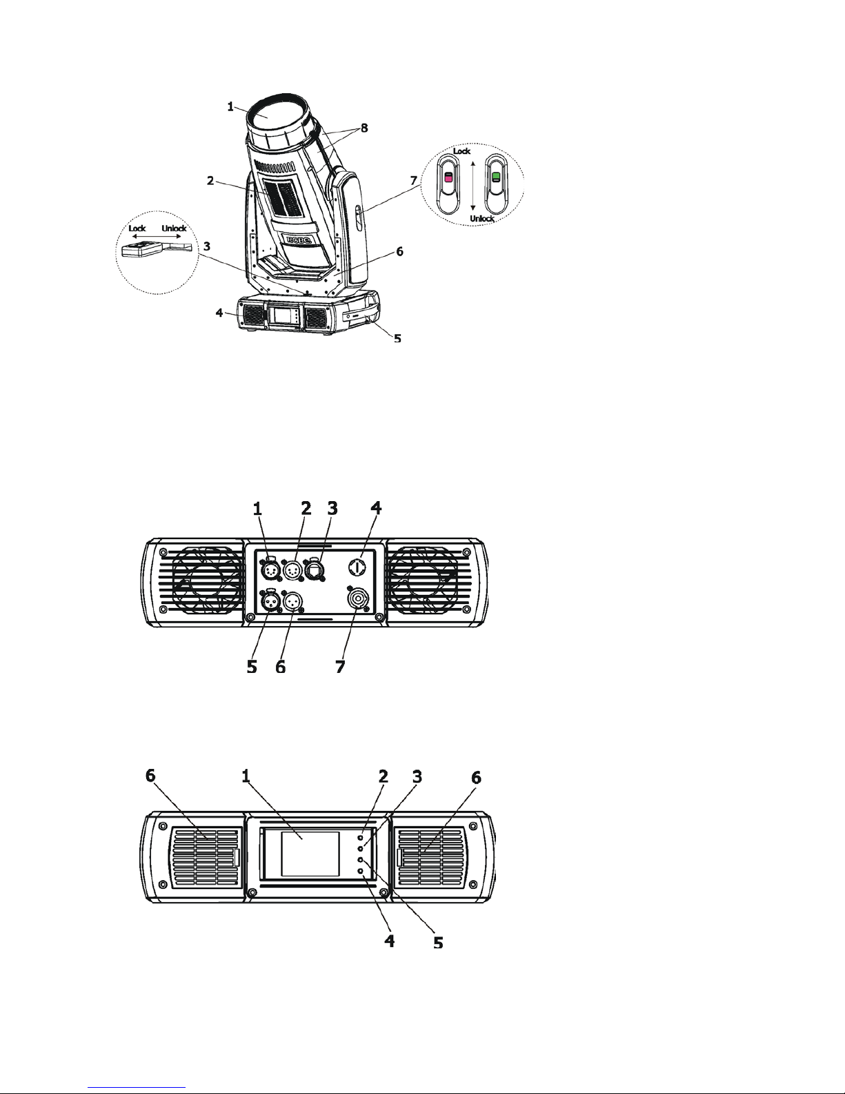
3. Fixture exterior view
Front panel of the base:
1 - Touch screen
2 - ESCAPE button
3 - NEXT button
4 - PREVIOUS button
5 - ENTER/DISPLAY ON button
6 - Dust lters
The head should be locked for transportation - the tilt lock (7) and the pan lock (3) have to be in the locked
positions. To unlock the head, move these latches to unlock positions before operating the xture.
1 - Front lens
2 - Air vents + lter
3 - Pan lock
4 - Air vents + lter
5 - Handle
6 - Yoke
7 - Tilt lock
8 - Head covers
The ENTER/DISPLAY ON button also serves for switching the display on when the xture is disconnected
from the mains.
Rear panel of the base:
1 - DMX output (5-pin XLR)
2 - DMX input (5-pin XLR)
3 - Ethernet input (RJ45)
4 - Fuse holder
5 - DMX output (3-pin XLR)
6 - DMX input (3-pin XLR)
7 - Power input (Neutrik
PowerCon)
6
4. Installation
Fixtures must be installed by a Qualied electrician in accordance with all
national and local electrical and construction codes and regulation.
4.1 Connection to the mains
For protection from electric shock, the xture must be earthed!
The Robin BMFL WashBeam is equipped with auto-switching power supply that automatically adjusts to any
50-60Hz AC power source from 200-240 Volts. The xture is protected by one 15 A blow primary fuse.
If you install a cord cap on the power cable to allow connection to power outlets, install a grounding-type (earthed)
plug, following the plug manufacturer’s instructions.
To apply power, rst check that the head pan and tilt locks are released.
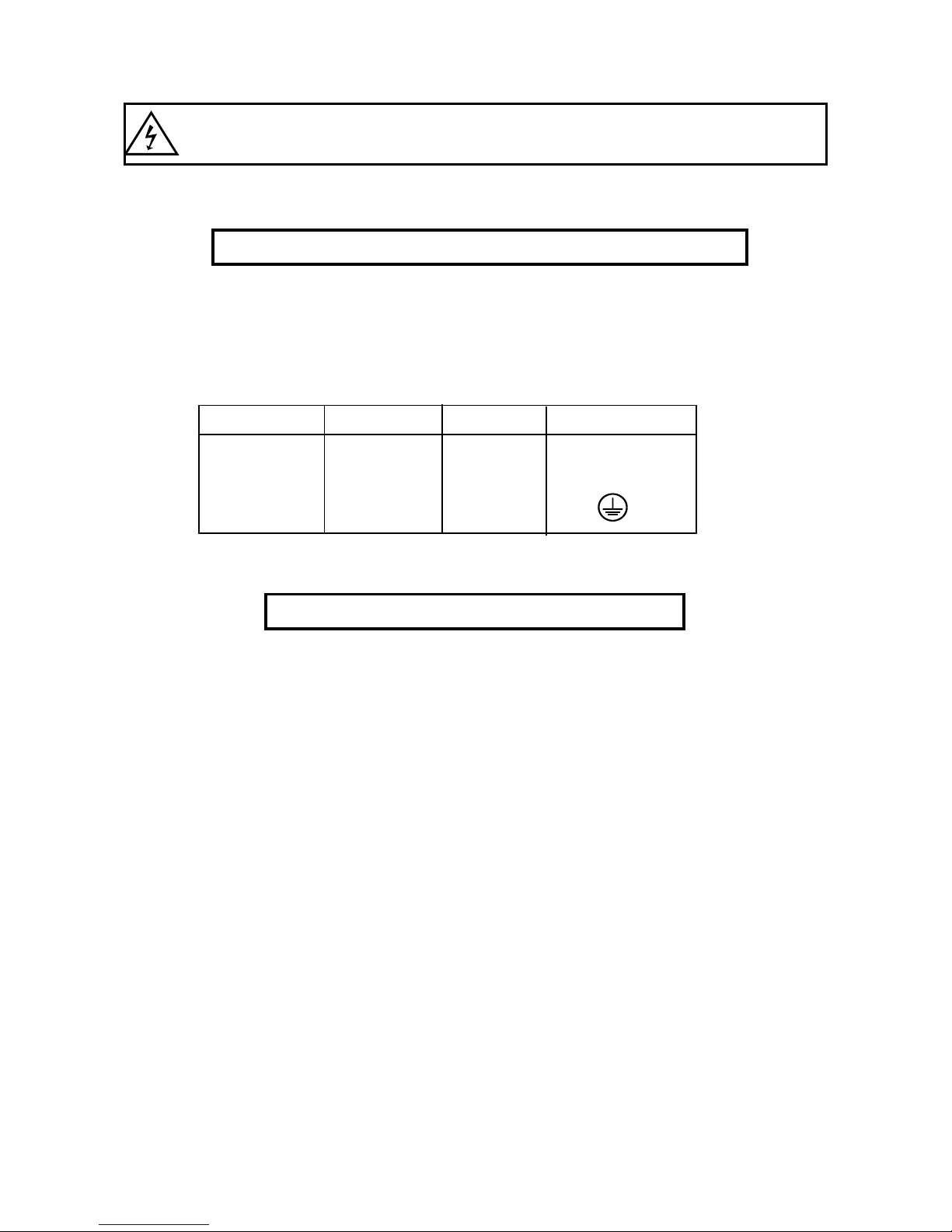
The cores in the power cable are coloured according to the following table.
Core (EU) Core (US) Connection Plug Terminal Marking
Brown Black Live L
Light blue White Neutral N
Yellow/Green Green Earth
The earth has to be connected!
If you have any doubts about proper installation, consult a qualied electrician.
Do not connect the xture to a dimmer system!
7
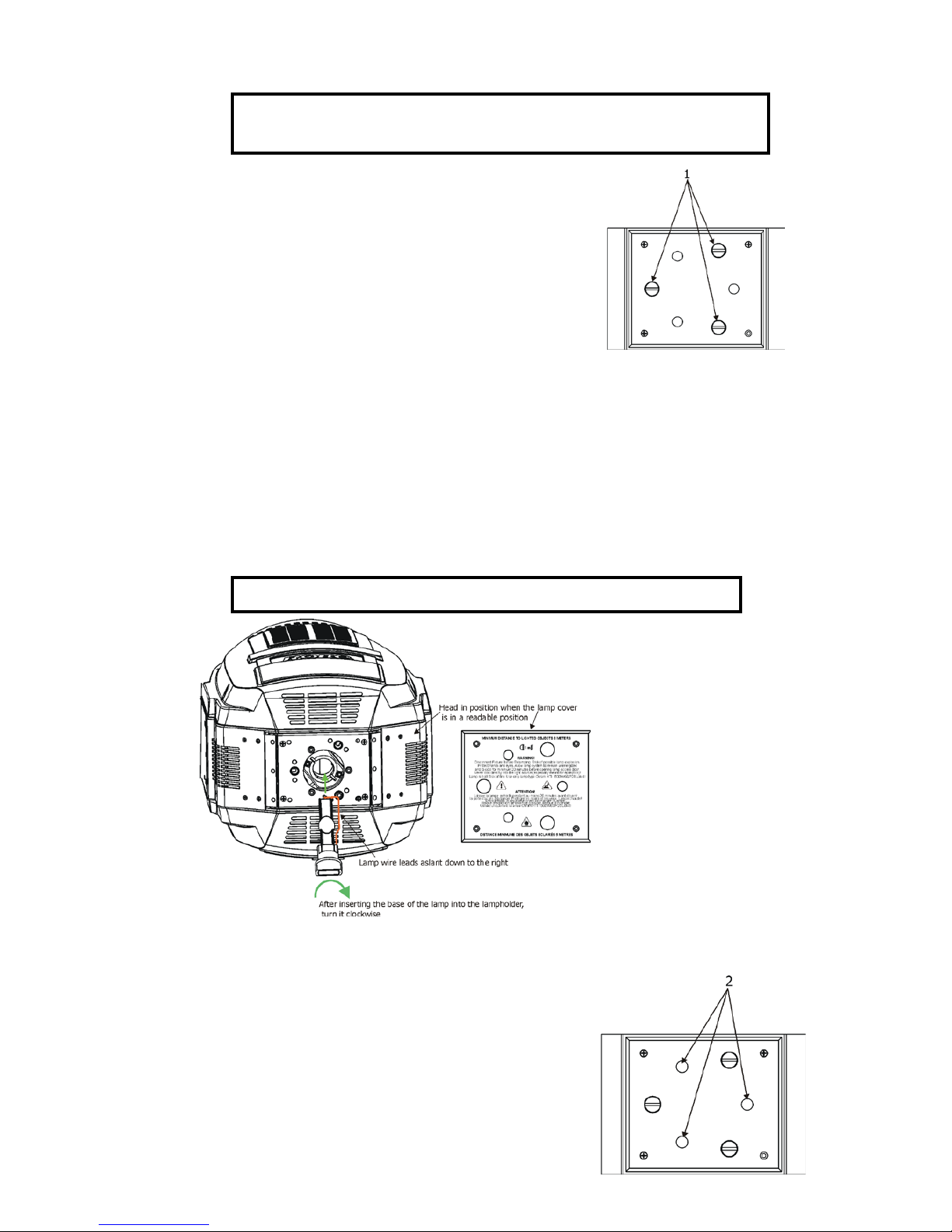
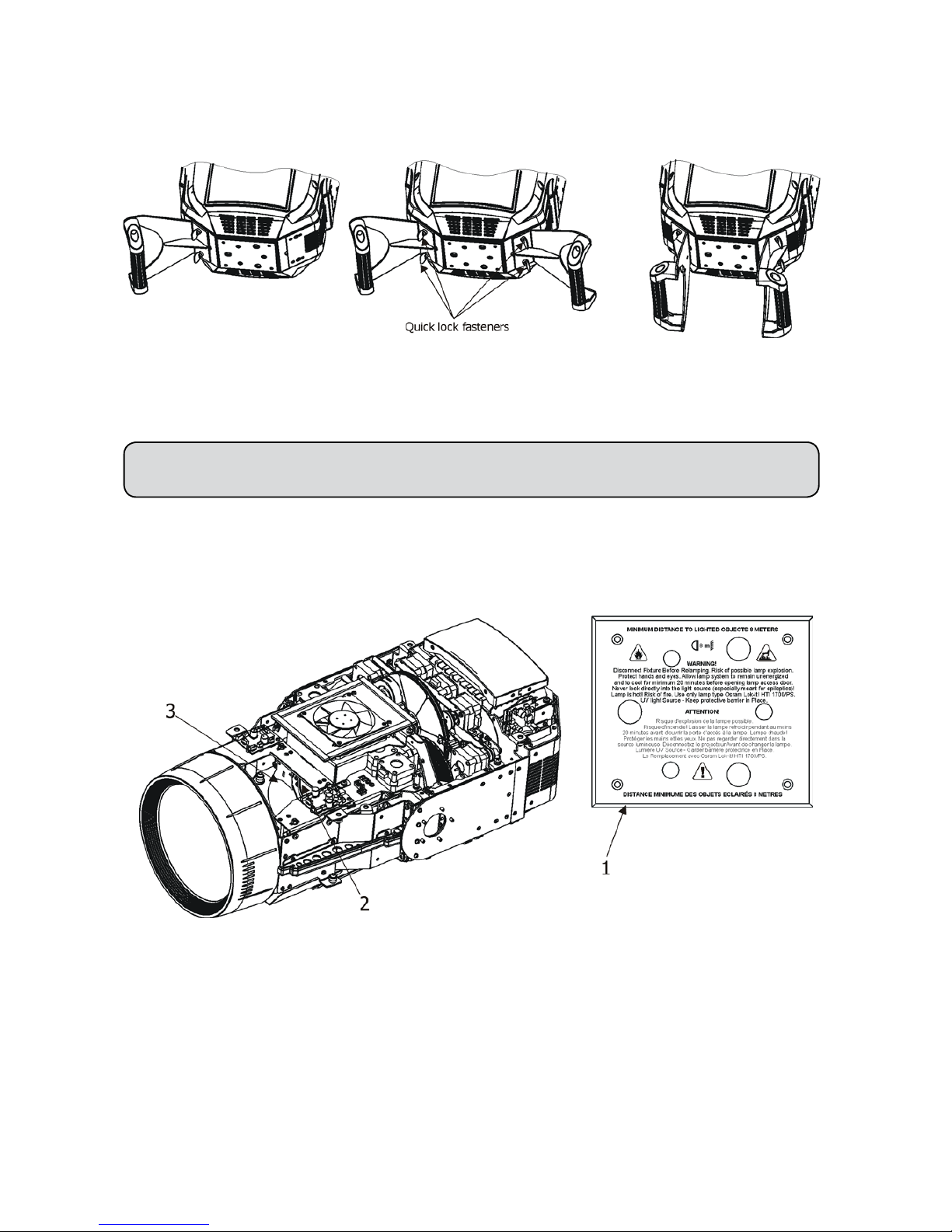
4.2 Installing the lamp
DANGER ! Install the lamp with the device switched off only.
Unplug from mains before !
To insert the new lamp.
1. Disconnect the xture from power and allow it to cool at least 20 minutes.
2. Make sure that the xture´s head is in the position as
shown on the picture (notices on the lamp cover are in
a readable position) .Loosen the three quarter-turn
fasteners (1) on the lamp cover to
open this cover.
3. Holding the lamp by its ceramic base, carefully
turn the lamp to the left to loosen the lamp from
the lamp holder.
Gently pull the lamp out of the lamp holder
4. Holding the new lamp by its ceramics base and keeping its orientation as shown at the picture below,
gently insert the lamp to the lamp holder and turn its base to the right until two lamp electrodes snap
into slots in the lamp holder. Make sure that the lamp is installed tightly into the lamp socket.
Do not install a lamp with a higher wattage! A lamp like this generates temperatures the device is not designed for. Damages caused by non-observance are not subject to warranty.
Please follow the lamp manufacturer‘s notes! Do not touch the glass bulb bare hand during the
installation!
5. Re-insert the lamp cover and tighten the three quarter-turn
fasteners (1).
6. Switch on the xture.
7. Align the lamp (see instructions below)
8. Reset the "Lamp On Time” and "Lamp Strikes” counters
in the menu "Information”.
Do not operate this xture with open lamp cover!
4.3 Lamp adjustment
The lamp holder is aligned at the factory. Due to differences between lamps,the ne adjustment may improve
light performance:
To adjust the lamp in the xture.
1. Switch on the xture and after its reset turn on the
lamp.
2. Go to the "Service" menu and select the item "Adjust
Lamp" to project the light beam on the wall.
3. Use items in this menu to focus the light beam
4. Turn adjustment screws (2) one after another until you
c
enter the hot spot (the brightest part of the beam) and
reach a max. light intensity at desired light distribution.
8
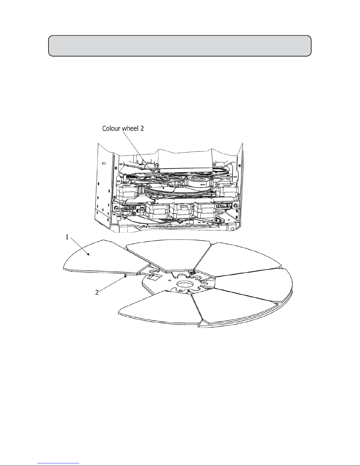
4.4 Replacing colour lters
Install colour lters with the device switched off only.
Unplug from mains before!
Colour lters
1. Disconnect the xture from mains and allow it to cool for 20 minutes.
2. Remove the plastic cover of the head by loosening the 4 quarter-turn fasteners on the cover.
3. Turn the colour wheel 2 to the suitable position.
The dichroic lters are xed on the colour wheel by the magnets.
4. Release the dichroic lter (1) from the colour wheel 2 by inclining it from its position
to break the power of the magnet
. Protect the glass lter with a piece of paper or clout.
5. Insert a new dichroic lter into the colour wheel 2.
6. Place the top cover back before applying power.

9
4.5 Replacing rotating gobos
Install gobos with the device switched off only.
Unplug from mains before!
To replace rotating gobos.
1. Disconnect the xture from mains and allow it to cool for 20 minutes .
2. Remove the plastic cover of the head by loosening the 4 quarter-turn fasteners on the cover.
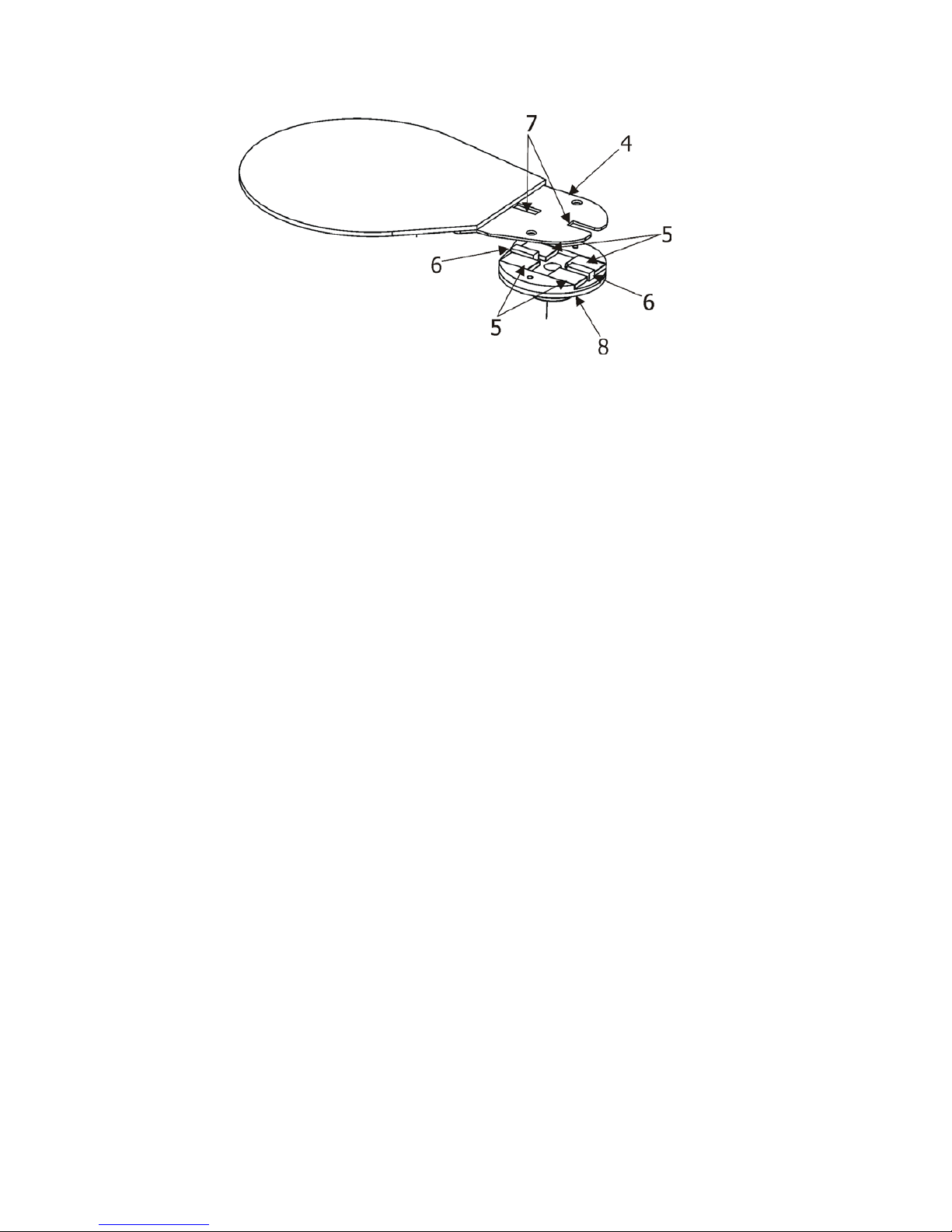
3. Gently pull up the gobo holder (3) from the rotation gobo wheel
.
4. Remove the spring lock (1) with an appro
priate tool (e.g. small-bladed screwdriver) and remove it.
Do not touch the surface of the pattern of the glass gobo with bare ngers.
5. Remove the original gobo (2) and insert the new one (glazy side towards the lamp).
The Robe gobo has a small position point (8) at its edge which has to aimed at the position point (4) on
the gobo holder (4). Insert the spring lock to secure correct gobo position in the gobo holder.
6. Insert he gobo holder back under the distance slots (6, 7) into rotating gobo wheel in this way, that its
position point (4) has to aimed at a small toothlike projection (5) on the edge of the rotating gobo wheel.
Important! When inserting the gobo holder back to the rotating gobo wheel, one of the adjacent gobo holder
has to be oriented according to the same rule, it means that its position point (4) has to aimed at
the toothlike
projection (5) on the edge of the rotating gobo wheel. You have keep both marks (4) and (5) side by side when
rotating the gobo wheel to the position allows inserting the gobo holder back.
5. Place the plastic cover back before applying power.
6. Use the menu Service to ne adjust replaced gobo (Service -> Calibration -> Calibrate effects -> R. Gobo
Index 1....6).
Note. The magnet (9) of the gobo holder has the same function as the position point (4) on the rest of gobo
holders.
10
4.6 Installing handle for the Follow Spot Mode
Before installation of handle (handles) , switch the xture to the Follow Spot Mode (Personality--> Follow Spot
Mode). You can install one or two handles in different positions as needed. See picture below. Before switching
the Follow Spot Mode off, remove handle (handles) from the xture.
4.7 Replacing heavy frost
Install heavy frost module with the device switched off only.
Unplug from mains before!
To replace the heavy frost module.
1. Disconnect the xture from mains and allow it to cool for 10 minutes.
2. Move the head to the position that signs on the lamp cover (1) lead up
3. Remove plastic cover of the head by loosening the 4 quarter-turn fasteners on the cover.
4. Move the zoom module
(2) towards front lens to get access to heavy frost (3).
Note: If you look into the xture through a front lens (lamp must be off !), you can see the heavy frost numberwhite number at a black holder. It is an easy way how to nd out a type of installed heavy frost in the xture
without taking head cover down. Heavy frost No. 20 is installed in the xture as default, another frosts 10° and
30° are included as standard accessories.
11
5
. The holder (4) of the frost lm is fastened to the frost holder (8) by means of the four magnets (5). Grip the
holder (4) and carefully tilt it out to break a force of magnets (5) on the frost holder (8).
6
. Insert a new frost module into the frost holder (8). Check, that both slots (6) snapped correctly into
two protrusions (7) on the holder (4)
7. P
lace the plastic cover back on the xture before applying power.
12
4.8 Rigging the xture
A structure intended for installation of the xture(s) must safely hold weight of the xture(s) placed on it. The
structure has to be certicated to the purpose.
The xture (xtures) must be installed in accordance with national and local electrical and construction codes
and regulation.
For overhead installation, the xture must be always secured with a safety wire that
can bear at least 10 times the weight of the xture
When rigging, derigging or servicing the xture staying in the area below the installation place, on bridges,
under high working places and other endangered areas is forbidden.
The operator has to make sure that safety-relating and machine-technical installations are approved by an expert
before taking into operation for the rst time and after changes before taking into operation another time.
The operator has to make sure that safety-relating and machine-technical installations are approved by a skilled
person once a year.
Allow the xture to cool for ten minutes before handling.
The projector should be installed outside areas where persons may walk by or be seated.
IMPORTANT! OVERHEAD RIGGING REQUIRES EXTENSIVE EXPERIENCE, including calculating working
load limits, installation material being used, and periodic safety inspection of all installation material and the
projector. If you lack these qualications, do not attempt the installation yourself, but use a help of professional
companies.
CAUTION: Fixtures may cause severe injuries when crashing down! If you have doubts concerning the safety
of a possible installation, do not install the xture!
The xture has to be installed out of the reach of public.
The xture must never be xed swinging freely in the room.
Danger of re !
When installing the device, make sure there is no highly inammable
material (decoration articles, etc.) in a distance of min. 1 m.
The minimum distance of 8 meters between light output from the moving head and the
lit objects must be kept!
CAUTION!
Use 2 appropriate clamps to rig the xture on the truss.
Follow the instructions mentioned at the bottom of the base.
Make sure that the device is xed properly! Ensure that the
structure (truss) to which you are attaching the xtures is secure.
The xture can be placed directly on the stage oor or rigged in any orientation on a truss without altering its
operation characteristics .
For securing a xture to the truss, install two safety wires which can hold at least 10 times the weight of the
xture. Use only the safety wires with screw-on carabines.
.
.
.
13
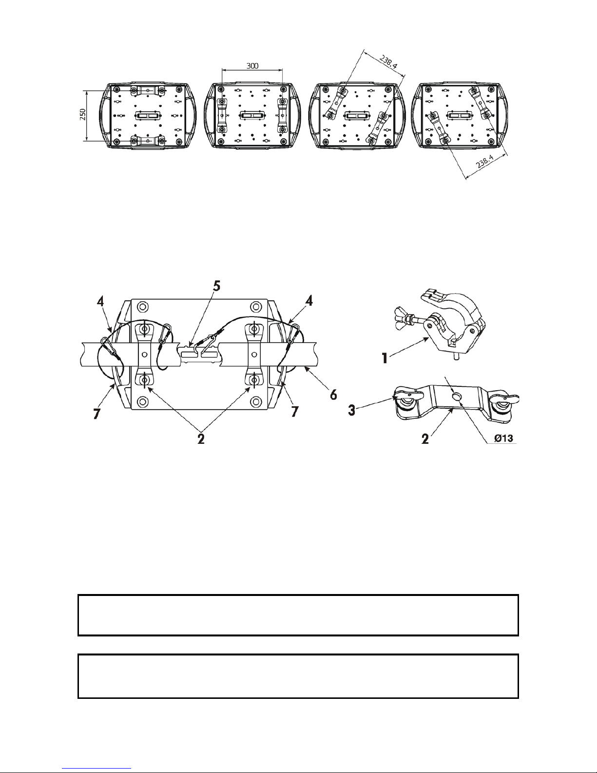
Omega holders positions:
Truss installation
1. Bolt each clamp (1) to the omega holder (2) with M12 bolt and lock nut through the hole in the holder.
2. Fasten the omega holders to the bottom of the base by inserting both quick-lock fasteners (3) into
the holes of the base and tighten fully clockwise.
3. Clamp the xture on a truss (6) and tighten the rigging clamps.
4. Pull one safety wire (4) around the truss (6) and through the handle (7) and another safety wire (4) pull
around the truss (6) and through the handle (7) and lock the screw-on carabine through attachment point (5)
as shown on the picture below.
When installing xtures side-by-side,
avoid illuminating one xture with another!
DANGER TO LIFE!
Before taking into operation for the rst time,the installation has to be approved by
an expert!
1-Clamp
2-Omega holder
3-Quick-lock fastener
4-Safety wire
5-Attachment point
6-Truss
7-Handle
14
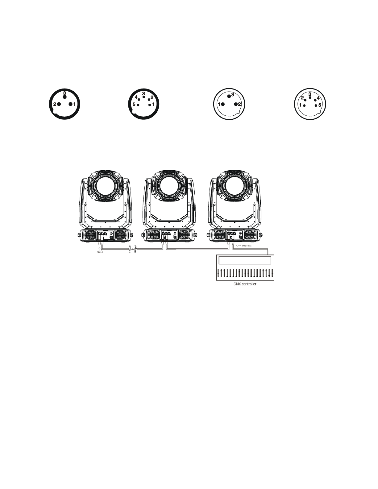
4.9 DMX-512 connection
The xture is equipped with both 3-pin and 5-pin XLR sockets for DMX input and output.The sockets are wired
in parallel.
Only use a shielded twisted-pair cable designed for RS-485 and 3-pin or 5-pin XLR-plugs and connectors in
order to connect the controller with the xture or one xture with another.
DMX - output DMX-input
XLR mounting-sockets (rear view): XLR mounting-plugs (rear view):
If you are using the standard DMX controllers, you can connect the DMX output of the controller directly with
the DMX input of the rst xture in the DMX-chain. If you wish to connect DMX controllers with other XLR outputs, you need to use adapter cables.
Building a serial DMX-chain:
Connect the DMX-output of the rst xture in the DMX-chain with the DMX-input of the next xture. Always
connect one output with the input of the next xture until all xtures are connected. Up to 32 xtures can be
connected.
Caution: At the last xture, the DMX-cable has to be terminated with a terminator. Solder a 120 Ω resistor be-
tween Signal (–) and Signal (+) into a 3-pin (5-pin) XLR-plug and plug it in the DMX-output of the last xture.
1 - Shield
2 - Signal (-)
3 - Signal (+)
4 - Not connected
5 - Not connected
1 - Shield
2 - Signal (-)
3 - Signal (+)
4 - Not connected
5 - Not connected
15
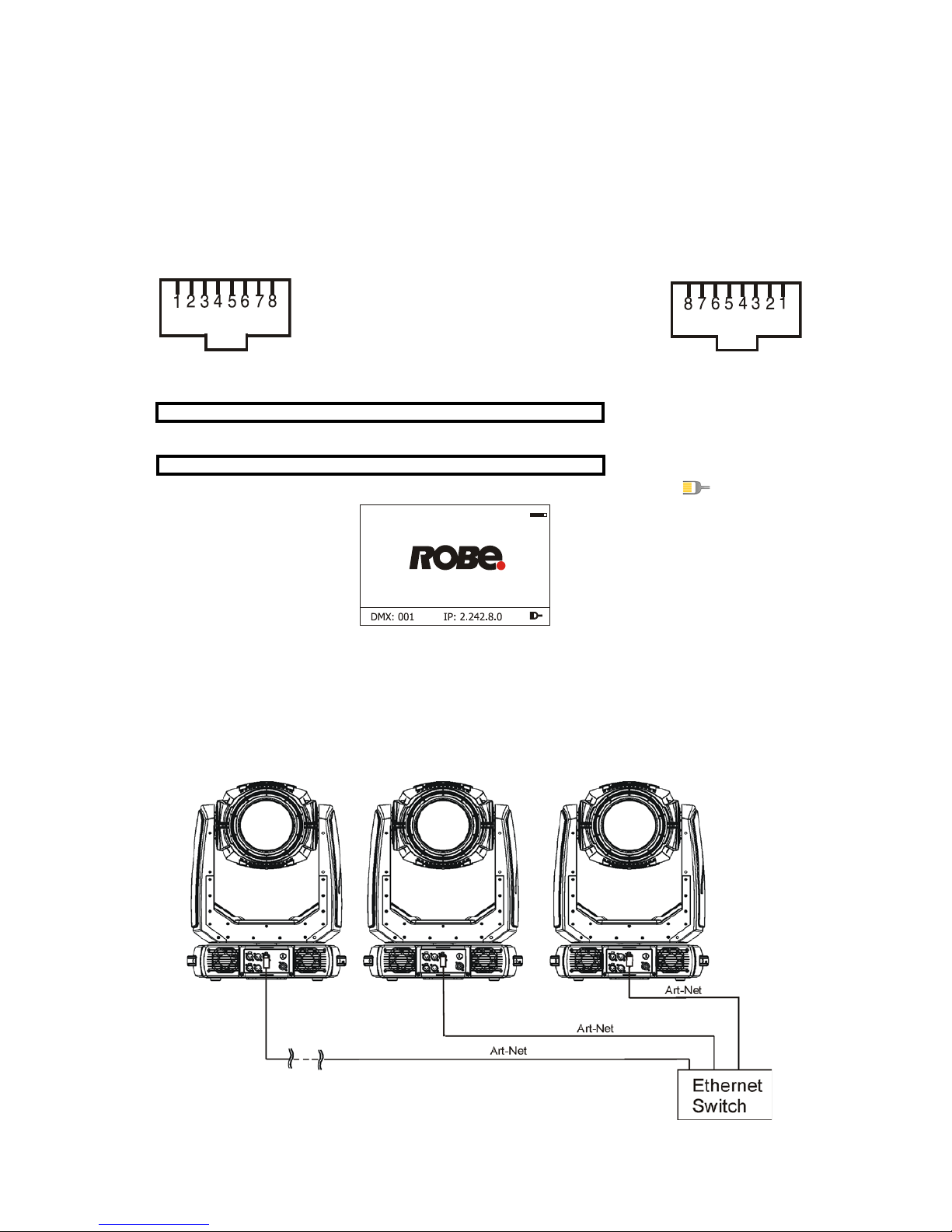
4.10 Ethernet connection
The xtures on a data link are connected to the Ethernet with ArtNet communication protocol.The control software running on your PC (or light console) has to support Art-Net protocol.
Art-Net communication protocol is a 10 Base T Ethernet protocol based on the TCP/IP.Its purpose is to allow
transfer of large amounts of DMX 512 data over a wide area using standard network technology.
IP address is the Internet protocol address.The IP uniquely identies any node (xture) on a network.
The Universe is a single DMX 512 frame of 512 channels.
The Robin MMX Blade is equipped with 8-pin RJ- 45 socket for Ethernet input.Use a network cable category 5
(with four “twisted” wire pairs) and standard RJ-45 plugs in order to connect the xture to the network.
RJ-45 socket (front view): RJ-45 plug (front view):
1- TD+ 5- Not connected
2- TD- 6- RX 3- RX+ 7- Not connected
4- Not connected 8- Not connected
Patch cables that connect xtures to the hubs or LAN sockets are wired 1:1,that is,pins with the same numbers
are connected together:
1-1 2-2 3-3 4-4 5-5 6-6 7-7 8-8
If only the xture and the computer are to be interconnected,no hubs or other active components are needed.
A cross-cable has to be used:
1-3 2-6 3-1 4-8 5-7 6-2 7-5 8-4
If the xture is connected with active Ethernet socket (e.g. switch) the network icon will appear at the
bottom right corner of the screen:
Direct Ethernet operation
Connect the Ethernet inputs of all xtures with the Ethernet network.
Option “ Artnet" (gMaI or gMA2 or sACN) has to be selected from “Ethernet Mode” menu at each xture.
Set IP address (002.xxx.xxx.xxx / 010.xxx.xxx.xxx) and the Universe at each xture.
An advised PC setting: IP address: 002.xxx.xxx.xxx / 010.xxx.xxx.xxx (Different from xture IP addresses)
NET mask: 255.0.0.0
(DMX address=150) (DMX address=42) (DMX address=1)
IP addres=002.168.002.004 IP addres=002.168.002.003 IP addres=002.168.002.002
Universe=1 Universe=1 Universe=1
16
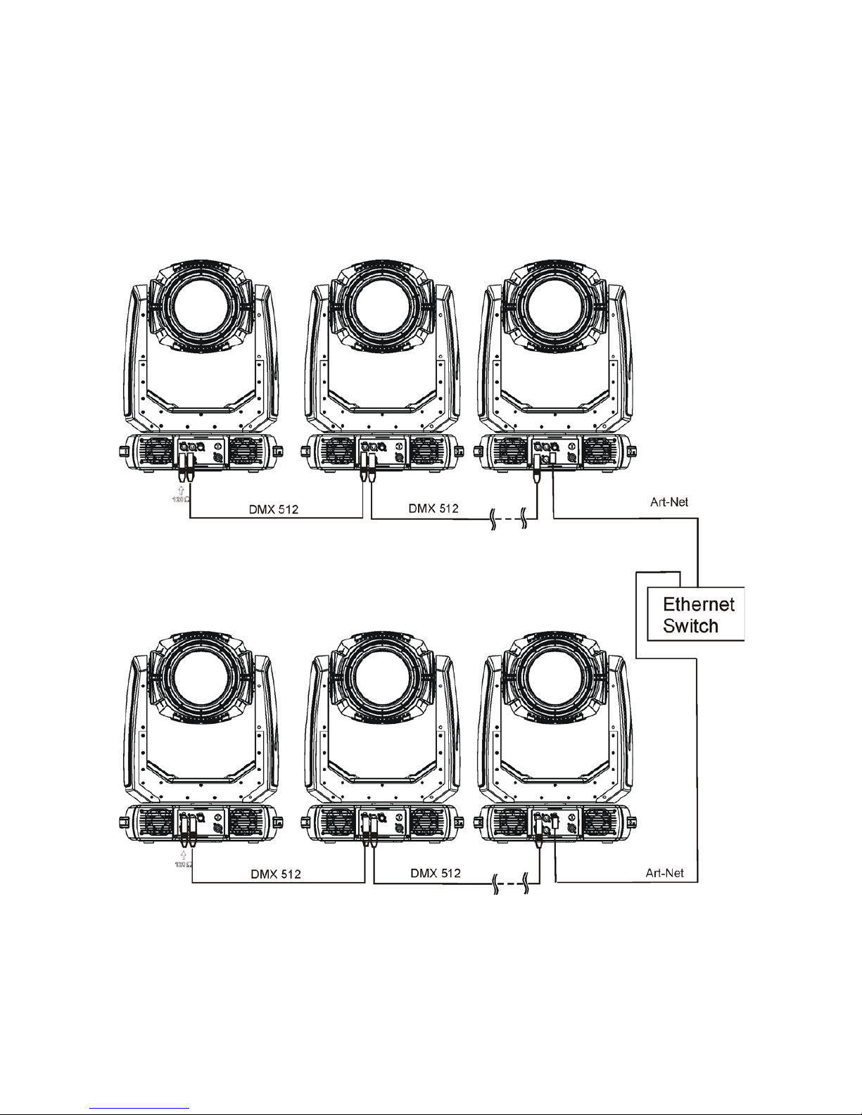
Ethernet / DMX operation
Option “ Artnet" (gMaI or gMA2 or sACN) has to be selected from “Ethernet Mode” menu at rst xture.
Option “Ethernet To DMX” has to be selected from the “Ethernet Mode” menu at the rst xture (connected to
the Ethernet) in the xture chain, next xtures have standard DMX setting.
Connect the Ethernet input of the rst xture in the data chain with the network. Connect the DMX output of this
xture with the input of the next xture until all xtures are connected to the DMX chain.
Caution: At the last xture, the DMX chain has to be terminated with a terminator. Solder a 120 Ω resistor
between Signal (–) and Signal (+) into a XLR-plug and connect it in the DMX-output of the last xture.
Example:
DMX address=1 DMX address=42 DMX address=150
IP addres=002.168.002.002
Universe=0
DMX address=1 DMX address=42 DMX address=150
IP addres=002.168.002.003
Universe=1

17
5. Remotely controllable functions
Lamp
The Osram Lok-it! HTI 1700/PS is a highly efcient, single-ended short-arc metal halide lamp with
6000 Kelvin colour temperature. The new Lok-it! plug’n’play system allows a quick one-touch lamp
replacement.
The xture allows three levels of the lamp power: 1700W, 1500W and Silent (silent mode - the lamp power is
auto-controlled to ensure minimum noise of xture fans).
Note: It is also important to note, that the discharge lamp is a cold restrike type, that means, that the lamp has
to be cold before re-striking. For this reason, you have to wait a while after having switched the lamp off before
you can switch it on again.
Colour wheel 1
This wheel contains 6 dichroic lters + open.The colour wheel can be positioned between two adjacent colours
in any position. It is also possible to rotate the colour wheel continuously at different speeds ("Rainbow effect“
in both directions).
Colour wheel 2
This wheel contains 6 replaceable 'SLOT&LOCK' dichroic lters + open.The colour wheel can be positioned
between two adjacent colours in any position. It is also possible to rotate the colour wheel continuously at dif-
ferent speeds ("Rainbow effect“ in both directions).
CMY+CTO colour mixing system
The CMY color mixing system is based on graduated cyan, magenta, and yellow colour lters. A continuous
range of colors may be achieved by varying the amount of each lter from 0 to 100%.
Effect wheel
The effect wheel rotating in both directions with variable speed which creates wide spectrum of graphic effects.
Rotating gobo wheel
The rotating gobo wheel includes with 6 glass gobos rotating in both directions, indexable, replaceable
"SLOT&LOCK” system Gobo positioning and gobo selection speed is available as well as a gobo-shake function.
Frost
Frost modules provide 3 types of frost ( heavy, medium, light) to create desired wash light. The heavy frost can
be replaced with two another frost lters which are included.
Iris
Motorized adjustable iris, wide range of variable pulse effects.
Zoom
Motorized zoom unit enables zoom between 5 °- 45° (open hole) in a beam application, in a wash application
according installed heavy frost: 7.5° - 48° (heavy frost 10°)
12° - 52° (heavy frost 20°)
14° - 56° (heavy frost 30°)
Focus
Motorized focus allows to focus beam from approx. 5 metres to innity.
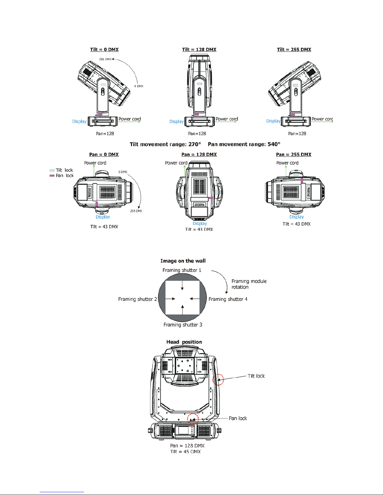
Framing shutters
4 individually positionable blades, rotation of each blade in range of 50°, rotation of the complete framing system in range of 90°
Shutter unit
This unit is used for strobe effects with variable speed.
Dimmer unit
Smooth 0 - 100 % dimming is provided by the mechanical dimmer unit.
18
Pan/Tilt
Fast pan/tilt movement due to built-in electronic motion stabilizer. The electronic motion stabilizer ensures precise
position of the xture´s head during its movement and reduces its swinging when the truss shakes.
Framing system
Framing system consists of four framing shutters which can be moved or swivelled to desired position separately.
 Loading...