

Page 1
Version 1.7
Page 2

2
Table of contents
1. Safety instructions ......................................................................................................... 3
2. Description of the Robin BMFL LightMaster ............................................................. 4
2.1 Control elements of the FollowSpot controller ........................................................... 5
3. Installation....................................................................................................................... 6
3.1 Installation of the BMFL xture on the tripod ............................................................ 11
4. Operation....................................................................................................................... 12
4.1 Functions mapping ................................................................................................... 12
4.2 Saving and recalling FollowSpot controller presets ................................................. 14
5. Control menu ................................................................................................................ 16
5.1 Menu Functions Mapping ......................................................................................... 17
5.2 Menu Show library ................................................................................................... 19
5.3 Menu All Lamps On/O ............................................................................................ 22
5.4 Menu Product IDs .................................................................................................... 22
5.5 Menu Software Version ............................................................................................ 22
5.6 Menu Settings .......................................................................................................... 22
6. Software update............................................................................................................ 23
7. Technical specications .............................................................................................. 24
8. Cleaning and maintenance .......................................................................................... 25
8.1 Disposing of the product .......................................................................................... 25
Page 3

3
FOR YOUR OWN SAFETY, PLEASE READ THIS USER MANUAL CAREFULLY
BEFORE YOU INSTALL THE PRODUCT .
1. Safety instructions
CAUTION!
The ROBIN BMFL LightMaster was designed for indoor use only.
The product is for professional use only, it is not for household use.
This product has left our premises in absolutely perfect condition. In order to maintain this condition and to
ensure a safe operation, it is absolutely necessary for the user to follow the safety instructions and warnings
written in this manual.
The manufacturer will not accept liability for any resulting damages caused by the non-observance of this
manual or any unauthorized modication to the product.
If the device has been exposed to drastic temperature uctuation (e.g. after transportation), do not switch it on
immediately. The arising condensation water might damage your device. Leave the device switched o until
it has reached room temperature.
Refer servicing to qualied service personnel.
Operate the ROBIN BMFL LightMaster only after having familiarized with its functions. Do not permit operation
by persons not qualied for operating the ROBIN BMFL LightMaster. Most damages are the result of unpro-
fessional operation!
Please use the original packaging if the ROBIN BMFL LightMaster is to be transported.
Please consider that unauthorized modications on the xture are forbidden due to safety reasons!
Page 4
4
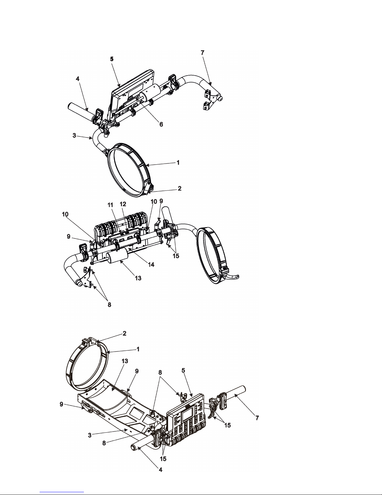
2. Description of the Robin BMFL LightMaster
1 - Collar
2 - Collar lock
3 - Handle bar (side version),
supporting frame (rear version)
4 - Handle
5 - FollowSpot controller
6 - USB (type A)
7 - Handle
8 - Fastening screws
9- Adjusting locks for the balance weight bar
( side version),
adjusting locks for the balance weight
(rear version)
10 - Spring locks of the FollowSpot controller
11- USB (type B)
12 - RJ 45
13 - Balance weight
14 - Base of the FollowSpot controller
15 - Adjusting locks for handle
Side version
Rear version
Page 5
5
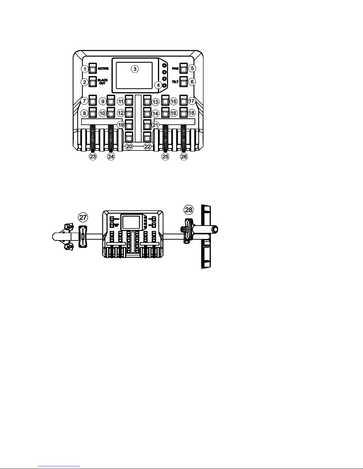
2.1 Control elements of the FollowSpot controller
1 - Active button (actives
the FollowSpot Controller)
2 - BlackOut button
3 - Graphic touch screen
4 - Switch On screen button
5 - Pan button(switches pan and tilt
motors from soft mode to
hard mode
6 - Tilt button(switches pan and tilt
motors from soft mode to
hard mode)
7 - Preset button
8 - Activating button for jog-wheel
(23)
9 - Preset button
10 - Activating button for rotary
jog-wheel (24)
11 - Preset button
12 - Preset button
13 - Preset button
14 - Preset button
15 - Preset button
16 - Activating button for
jog-wheel (25)
17 -Preset button
18 - Activating button for
jog-wheel (26)
19 - Preset button
20 - Preset button
21 - Preset button
22 - Preset button
23 - Jog-wheel
24 - Jog-wheel
25 - Jog-wheel
26 - Jog-wheel
27 - Left fader
28 - Right fader
Page 6
6
3. Installation
The Robin BMFL LightMaster has to be installed by a qualied worker on
the following xtures only: Robin BMFL FollowSpot, Robin BMFL Spot, Robin BMFL
Blade, Robin BMFL WashBeam.
Important!
Switch the Robin BMFL xture to the Follow Spot Mode (option Soft) before
installing the Robin BMFL LightMaster.
Robin BMFL LightMaster Side
1. Switch the BMFL xture to the Soft option of the Follow Spot Mode (Personality-->Follow Spot Mode -->Soft).
2. Disconnect the xture from mains and place it on a at surface (e.g. table). Move the head to a horizontal
position and lock the tilt movement.
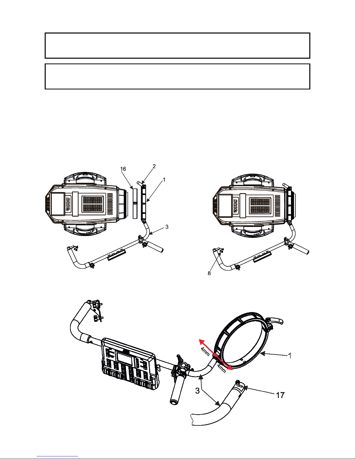
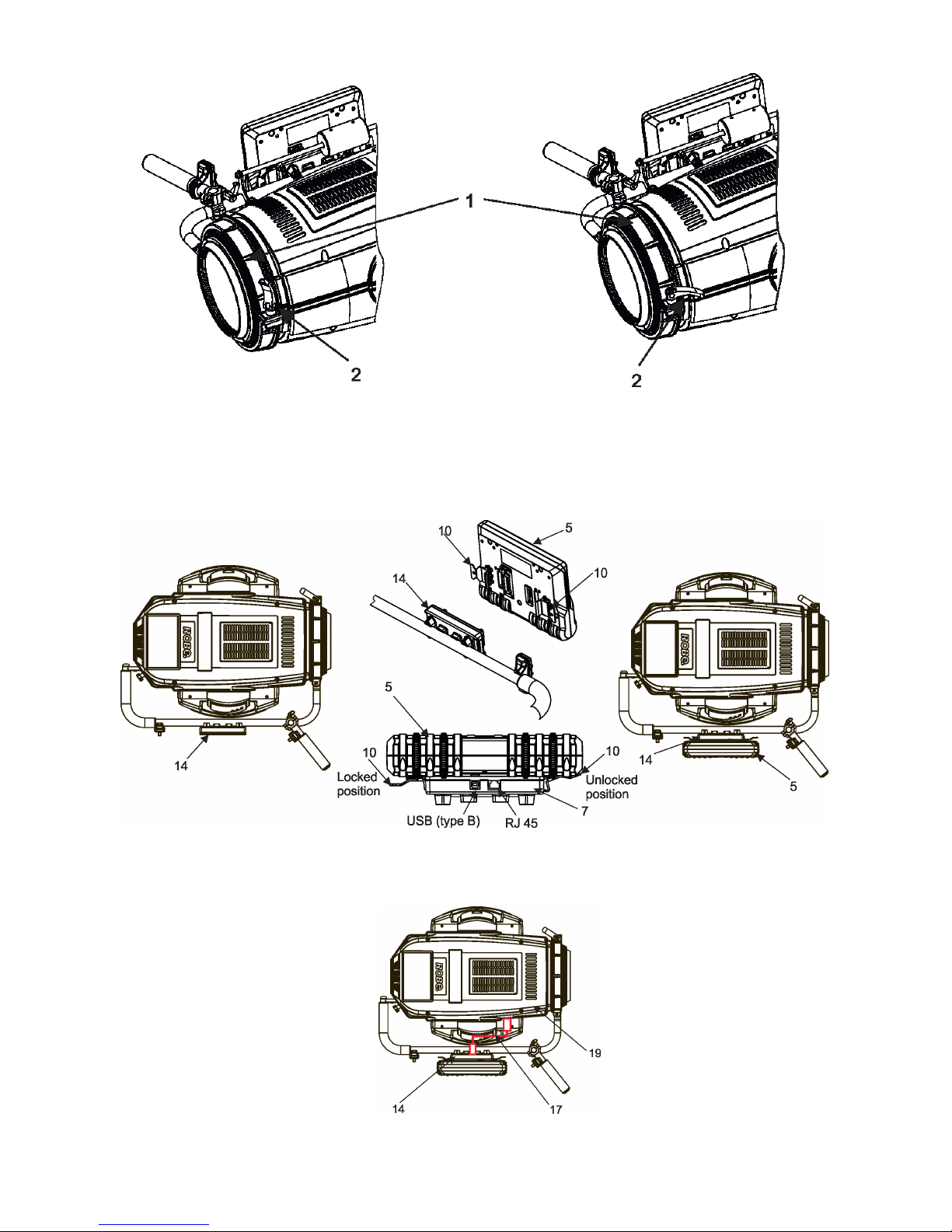
3. Place the collar (1) of the handle (2) on the front part of the xture head.
If you install the Robin BMFL LightMaster on the Robin BMFL WashBeam, remove the rubber ring (16) from
the collar (1).
4. Fasten the second side of the handle bar (2) to the head by means of two screws (8).
5. Secure the collar (1) on the head by means of the collar lock (2).
Note: There is a groove (17) in the handle bar (3). The groove allows movement of the collar (1) in the range of
8 mm in order to place the collar on the xture head correctly (especially on the BMFL Spot/FollowSpot head).
Page 7
7
Collar lock (2) in the unlocked position. Collar lock (2) in the locked position.
By turning the lock (2) clockwise you will tighten
the collar (1). Do not use brute force!
6. Attach the FollowSpot Controller (5) to the FollowSpot Controller base (14). During attaching, both spring
locks (10) have to be in an unlocked position (pressed towards the Follow Spot Controller).
7. Connect the FollowSpot Controller base (14) with the xture head (19) by means of the USB cable (17).
Page 8

8
This USB connection with xture head is possible for the Robin BMFL FollowSpot only.
If you use the Robin BMFL Spot, Robin BMFL Blade or Robin BMFL WashBeam, connect the FollowSpot
Controller base (14) with the xture base (18) by means of the USB cable (17).
8. Use the balance weight (13) to balance the head in a horizontal position.
Note: The FollowSpot Controller with its base can be tilted +/-15°( from a vertical axis) on the handle bar.
Page 9

9
Robin BMFL LightMaster Rear
The installation should do two workers as the supporting frame is heavy.
Danger!
Never put ngers between the balance weight (13) and the supporting frame (3)
when you adjust the position of the balance weight. There is a danger of injury of
your ngers by the heavy balance weight.
Always secure adjusted position of the balance weight by means of two locks (9).
1. Switch the BMFL xture to the Soft option of the Follow Spot Mode (Personality-->Follow Spot Mode -->Soft).
2. Disconnect the xture from mains and place it on a at surface (e.g. table). Move the head to a horizontal
position and lock the tilt movement.
3. Place the collar (1) of the supporting frame (3) on the front part of the xture head.
If you install the Robin BMFL LightMaster on the Robin BMFL WashBeam, remove the rubber ring (16) from
the collar (1).
4. Fasten the second side of the supporting frame (3) to the head by means of four screws (8).
5. Secure the collar (1) on the head by means of the collar lock (2).
Collar lock (2) in the unlocked position. Collar lock (2) in the locked position.
By turning the lock (2) clockwise you will tighten
the collar (1). Do not use brute force!
Page 10

10
6. Attach the FollowSpot Controller (5) to the FollowSpot Controller base (14). During attaching, both spring
locks (10) have to be in an unlocked position (pressed towards the Follow Spot Controller).
7. Connect the FollowSpot Controller base (14) with the xture head (19) by means of the USB cable (17).
This USB connection with xture head is possible for the Robin BMFL FollowSpot only.
If you use the Robin BMFL Spot, Robin BMFL Blade or Robin BMFL WashBeam, connect the FollowSpot
Controller base (14) with the xture base (18) by means of the USB cable (17).
8. Use the balance weight (13) to balance the head in a horizontal position. Always secure the balance weight
in adjusted position by means of the balance locks (9).
Page 11

11
3.1 Installation of the BMFL xture on the tripod
1. Unfold and adjust height of the tripod and distance of legs (8) by means of adjusting locks (4,5,6,7).
The lock (3) has to be in a lower position (as shows arrow on picture below).
2. After inserting the adaptor (1) with spigot (2) to the tripod, the spigot (2) has to be secured by means of
the lock (10) and the adaptor (1) by means of the pin (11) which is inserted to the hole (13) of the adaptor (1)
as shows arrow on picture below. Position of the pin(11) has to be secured by means of the lock (12).
3. The four quarter -turn locks (9) of the adaptor serve for fastening the BMFL xture with installed LightMaster
on the tripod with adaptor. Two workers should install the BMFL xture on the assebled tripod with the adaptor.
Check all quarter -turn locks (9) are fully tightened before operating the BMFL xture.
Check that all locks (3, 4, 5,6,7, 10,12) are fully tightened before placing the BMFL
xture with installed LightMaster on the tripod with adaptor.
Page 12

12
4. Operation
After installing the ROBIN BMFL LightMaster on the xture and connecting with the xture via USB cable,
connect the xture to mains and leave it to perform resets (except pan/tilt reset).
After nishing resets, the xture is in the FollowSpot mode with pan/tilt motors in the Soft mode.
Press the button ACTIVE (1) in order to activate the FollowSpot Controller. By pressing either the PAN button
(5) or the TILT button (6) you will switch both pan and tilt motors of the xture to the Hard mode of the FollowSpot mode.
The button BLACK OUT (2) closes light output of the xture.
4.1 Functions mapping
After switching the xture on, the touch screen of the FollowSpot Controller shows the initial screen:
Note: the massage "Waiting for controller" means the FollowSpot Controller is not connected with the xture
via USB cable.
Touch the icon to display the password entering screen:
Enter the password (default password is 5242) to enter the main menu of the FollowSpot Controller. The password prevents unauthorized person from changing setting of the FollowSpot Controller.
Enter the menu "Functions Mapping". The list of available eects will appear:
If the message" Please Activate FollowSpot Controller!" will appear, press the ACTIVE button (1) on the Follow
Spot Controller.
Page 13

13
To assign an eect to the Jog-wheels and faders
1.Touch desired eect. Buttons (8/10/16/18) which activate jog-wheels (23/24/25/26) and buttons (20/22), which
matches faders (27/28) will start to ash.
2.Press desired button and selected eect will be assigned to its jog-wheel (fader).
Assigned eect is displayed in a yellow colour, free eects stay in a white colour.
3.Repeat steps 1 and 2 for needed eects.
4.Touch the [cancel] icon and than [back arrow] icon. The screen with eect faders will appear.
E.g.
Sensitivity of the jog-wheels assigned to the eects can be set at three levels: low, medium and high.
The levels of the sensitivity are marked in colour on the screen:
low level - green slider
medium level -yellow slider
high level- red slider
In order to switch a jog-wheel to desired level of sensitivity, press and hold its activating button (8/10/16/18)
until the colour of fader is changed.
Eects assigned to the four jog-wheels and two faders have a priority over DMX values coming from a DMX
controller.
Only eects assigned to the jog-wheels will
appear on this screen.
Eects assigned to faders (27/28) will not
be shown.
Page 14

14
Functionality of the BMFL LightMaster can by restricted by means of commands on the channel Power/Special
Functions of the Robin BMFL xtures as follows:
240-244 DMX -LightMaster enabled
245-249 DMX - LightMaster disabled (except two faders on its handle bar and pan/tilt)
250-255 DMX - LightMaster disabled (except pan/tilt)
To control desired eect
1.Use its fader on the screen or press the activating button for its jog-wheel and use this jog wheel or use a
corresponding fader.
The FollowSpot Controller overwrites xture channels which are mapped to its jog-wheels or faders, excepting
a dimmer. The dimmer value is a combination of value coming from DMX console and a value on the FollowSpot Controller (e.g. DMX console sends 180 DMX, jog-wheels shows 50%, real DMX value coming to xture
is 90 DMX).
In case that the DMX console does not send DMX data, the FollowSpot Controller allows full range (0-255
DMX) of dimmer control.
To release an eect from the jog-wheel (fader)
1.Touch desired eect from the list of eects in the menu "Functions Mapping".
2.Touch the option "Unlink".
3.The eect will be displayed in a white colour.
The item "All" allows to release all assigned eects at one go.
4.2 Saving and recalling FollowSpot controller presets
The FollowSpot Controller oers to save up to 12 presets.
To save a preset
1. Press and hold one of the preset buttons (7/9/11/12/13/14/15/17/19/20/21/22) e.g. button (7) until the jogwheels activating buttons (8/9/16/18) and the pan/tilt buttons (5/6) start to ash.
2. Press ashing button of eect which value you wish to add to the current preset (the button will start light
continually).
Note: values on faders
cannot be included to
presets.
Page 15

15
3. Press and hold selected preset button until jog-wheels activating buttons stop to ash.
Note: the FollowSpot controller presets are common for all user show and cannot be saved on the USB ash
drive.
If you use the FollowSpot Controller in the RoboSpot, the FollowSpot controller presets will be overwriten by
presets from RoboSpot.
To recall the FollowSpot controller preset
Press a button with stored FollowSpot Controller preset.
To delete the FollowSpot controller preset
1. Press and hold desired preset button until the jog-wheel activating buttons (8/10/16/18) and the pan/tilt
buttons (5/6) start to ash.
2. Press and hold selected preset button until the jog-wheels activating buttons stop to ash. Do not press any
jog-wheels activating button. The preset button will stop to light.
Note: you can write notes on the white elds of the FollowSpot Controller, use a marker on an alcohol base and
a suitable cleaning liquid (on alcohol base) for removing the notes. Never use solvents!
Page 16

16
5. Control menu
The FollowSpot Controller is equipped with the QVGA Robe touch screen with battery backup which
allows to set the device behaviour according to your needs.
Icons used in the touch screen menu:
- [back arrow] used to move back to the previous screen (or menu level).
- [up arrow] used to move up on the previous page.
- [down arrow] used to move down on the next page.
- [conrm] used to save adjusted values and leave menu or to perform desired action.
- [cancel] used to leave menu without saving changes.
- [display on/o] used to switch on/o the display.
- [menu enter] used to enter xture menu.
Note: buttons are not functional yet.
Touch the icon to display the password entering screen:
Enter the password (5242) to enter the main menu of the FollowSpot Controller. The password prevents unauthorized person from changing setting of the FollowSpot Controller.
Main menu
Page 1 Page 2
Page 17

17
5.1 Menu Functions Mapping
By entering the menu you can assign eects from the list of available eects to the jog-wheels and faders.
The item All - releases all assigned eects at one go.
List of available eect channels depends of used moving head:
Fixture Eect Available DMX values
Robin BMFL FollowSpot
Dimmer 0-255
Iris 0-179
Focus 0-255
Zoom 0-255
L Frost 0-254
M Frost 0-254
H Frost 0-254
Color 1 0,130-189
Color 2 0,130-189
Cyan 0-255
Magenta 0-255
Yellow 0-255
CTO 0-255
Fixture Eect Available DMX values
Robin BMFL Spot
Dimmer 0-255
Iris 0-179
Focus 0-255
Zoom 0-255
L Frost 0,1-50
M Frost 0,87-136
H Frost 0,173-222
Color 1 0,130-189
Color 2 0,130-189
Cyan 0-255
Magenta 0-255
Yellow 0-255
CTO 0-255
DgW. pos 0-127
DgW. r1 0-255
DgW. r2 0-255
RGW 1 0,32-59
RGWr 1 0-255
RGW 2 0,32-59
RGWr 2 0-255
Prism 0-127
Pris r 0-255
Page 18

18
Fixture Eect Available DMX values
Robin BMFL Blade
Dimmer 0-255
Iris 0-191
Focus 0-255
Zoom 0-255
L Frost 0,1-50
M Frost 0,87-136
H Frost 0,173-222
Color 1 0,130-189
Color 2 0,130-189
Cyan 0-255
Magenta 0-255
Yellow 0-255
CTO 0-255
Efw. pos 0-127
Efw. rot 0-255
SGW 0, 8-103
RGW 1 0,32-59
RGW r1 0-255
Prism 0-127
Pris r 0-255
FS rot 0-255
FS 1 m 0-255
FS 1 s 0-255
FS 2 m 0-255
FS 2 s 0-255
FS 3 m 0-255
FS 3 s 0-255
FS 4 m 0-255
FS 4 s 0-255
Fixture Eect Available DMX values
Robin BMFL WashBeam
Dimmer 0-255
Iris 0-179
Focus 0-255
Zoom 0-255
L Frost 0-254
M Frost 0-254
H Frost 0-254
Color 1 0,130-189
Color 2 0,130-189
Cyan 0-255
Magenta 0-255
Yellow 0-255
CTO 0-255
Efw. pos 0-127
Efw. rot 0-255
Page 19

19
Fixture (continuing) Eect Available DMX values
Robin BMFL WashBeam
RGW 1 0,32-59
RGWr 1 0-255
FS rot 0-255
FS 1 m 0-255
FS 1 s 0-255
FS 2 m 0-255
FS 2 s 0-255
FS 3 m 0-255
FS 3 s 0-255
FS 4 m 0-255
FS 4 s 0-255
5.2 Menu Show library
The menu item oers 10 user shows. In the show is saved:
Functions mapping of the FollowSpot Controller
Sensitivity of jog-wheels
Faders switching and inversion
The show can be saved on a USB ash drive and load to the FollowSpot Controller if need.
To select a show
1. Enter the menu "Select/rename Show"
2. Select desired show and conrm it.
To rename a show
1. Select a show and touch the Edit button.
Edit button
Down button
Conrm button
Cancel button
Page 20

20
2. Edit the name of selected show by means of the alphanumerical keyboard.
Function keys has the following meaning:
ALT key- switches among keyboards:
DEL key - deletes a character
Sh key - shift key, changes order of displayed characters aA ---> Aa.
The key 0_ serves as a space bar.
To export a show
1. Disconnect the FollowSpot Controller from the FollowSpot Controller base and connect a USB ash drive to
the USB port on the bottom side of the FollowSpot Controller.
2. Press and hold the On button until the graphic touch screen will light (the screen lights about 20 sec and
after that will be switched o unless you touch any icon).
Page 21

21
3. Select option "Export Show"
4. Select show and conrm it.
Wait until the message "Show Saved" appears on the screen. Touch the Cancel button.
Default name of saved show le on the USB ash drive has the following sentence structure
e.g. lightmaster-1-0031.cfg
lightmaster-2-0031.cfg
where the number 1 (2,3,...10) represents a number of show, the number 0031 represents last four numbers
of RDM UID of the FollowSpot Controller.
Note: if you save some show more than once, original le is not overwritten, les are dierentiated by a number
after underscore character e.g:
lightmaster-2-0031.cfg
lightmaster-2-0031_1.cfg
lightmaster-2-0031_2.cfg
To import a show
1. Disconnect the FollowSpot Controller from the FollowSpot Controller base and connect a USB ash drive to
the FollowSpot Controller and switch the graphic touch screen on as described above in article To export a show.
2.Select option "Import Show"
3. Select show to which you want to load a show le from the USB ash drive and conrm it.
Page 22

22
4. Select desired show le to load it.
After loading, the message " Show Loaded" will appear on the screen: Touch the Cancel button.
5.3 Menu All Lamps On/O
The menu item allows to switch on/o lamp in the Robin BMFL FollowSpot.
5.4 Menu Product IDs
Select this menu item to read a MAC Address , RDM UID, and RDM Label.
5.5 Menu Software Version
Select this item to read the software version of the xture modules:
Display System - a display processor
Module C - a control panel processor
5.6 Menu Settings
System Test - the menu allows you to test jog-wheels and faders.
Ethernet Settings - The menu allows to set the FollowSpot Controller for Ethernet operation.
Ethernet Mode
Artnet - Fixture
receives Artnet protocol
gMAI
- Fixture
receives MANet I protocol
gMA2
- Fixture
receives MANet 2 protocol
sACN
- Fixture
receives sACN protocol
IP Address/Net Mask - Select this menu to set IP address. IP address is the Internet protocol
address.The IP uniquely identies any node (xture) on a network.
There cannot be 2 xtures with the same IP address on the network!
Default IP Address -Preset IP address, you can set up only rst byte of IP address
(2 or 10) e.g. 002.019.052.086.
Custom IP Address - The option enables to set up all bytes of IP address.
Net Mask - The option enables to set up all bytes of Net Mask.
ArtNet Universe - Use
this item to set a Universe (0-255). The Universe is a single DMX
512 frame
of 512 channels.
MANet Settings - Use this menu to set parameters for MANet operation.
MANet Universe I/II - The value of this item can be set in range 1-256.
MANet Session ID - The value of this item can be set in range 1-32.
sACN Settings - Use this menu to set parameters for sACN operation.
sACN Universe - The value of this item can be set in range 1-32000.
sACN Priority - The value of this item can be set in range 0-255.
Controls invert - the menu item allows you to invert faders of the Light Master.
Default settings of faders: fader down-minimum (0 DMX), fader up-maximum (255 DMX).
Page 23

23
Faders Switch - swaps functions of faders.
Password Settings - the menu item allows you to change the password or switch it on/o at entry the
FollowSpot Controller menu.
Change password - use this option to change password. Default (factory) password is 5242.
Protect with Password - If this function is on, the password is required at entry the FollowSpot
Controller menu.
Note: both menu items stated above require inserting of password to enter them even the password is
set o ! You have to remember last set password!
In case you have forgotten your password, use the master password 4678.
Recalibrate Touchscreen - The item starts calibration of the touchscreen. Follow instructions on
the screen.
Default Settings - The menu item allows you to set the items stated above (except Ethernet Settings) to default
values.
Note: the password will not be set to a default password (set password will remain without change) but the
option "Protect with Password will be set to On".
6. Software update
The FollowSpot Controller software update is done via a network connection between a computer running a
ROBE RDM Uploader software through the RJ45 input of the FollowSpot Controller base. It is important to
note, that the FollowSpot Controller IPv4 address has to be set to 2.x.x.x network (for example 2.0.1.10) with
netmask 255.0.0.0 . During the update, the FollowSpot Controller has to be attached to FollowSpot Controller
base and this base has to be connected to the BMFL xture by means of the USB cable. The BMFL xture has
to be connected to mains.
To update software in the FollowSpot Controller.
1. Connect a computer running ROBE RDM Uploader to the internet and update software libraries (Libraries
→ Update)
2. Connect the computer and the FollowSpot Controller base via Ethernet cable.
3. Set computer to address 2.x.x.x/255.0.0.0. Do not change any IP settings on the FollowSpot Controller.
4. Use the ROBE Uploader → Devices → Discovery and Devices → Update. This will update the FollowSpot
Controller.
Page 24

24
7. Technical specications
Input voltage: 5V DC
Setting & Control: graphic touch screen
Number of control elements: 20 buttons, 4 jog-wheels and 2 faders
Connection: 1 x USB A,1x USB B, 1x RJ45
Fastening: via 2 (4) screws and collar with lock
Weight: 4 kg (side version),10.7kg (rear version)
Dimensions (mm)
Side version
Page 25

25
Rear version
Included items
1 x Robin BMFL LightMaster (side or rear)
1 x BMFL Base adaptor for FollowSpot (P/N 10980365)
1 x Tripod for RoboSpot, FollowSpot, LightMaster (P/N 10980350)
1 x USB cable A-B, 1.8m length (P/N13050756)
1 x User manual
8. Cleaning and maintenance
A soft lint-free cloth moistened with suitable cleaning uid is recommended, under no circumstances should
solvents be used!
More complicated maintenance and service operations are only to be carried out by authorized distributors.
8.1 Disposing of the product
To preserve the environment please dispose or recycle this product at the end of its life according to the local
regulations and codes.
Copyright © 2017-2018 Robe Lighting - All rights reserved
Specications are subject to change without notice.
December 6, 2018
Made in CZECH REPUBLIC by ROBE LIGHTING s.r.o. Palackeho 416/20 CZ 75701 Valasske Mezirici
 Loading...