

Page 1
Ver. 1.
5
Page 2

LiteWare HO2
2
Table of contents
1. Safety instructions ...................................................................................................................................................... 3
2. Fixture exterior view ................................................................................................................................................... 5
3. Installation .................................................................................................................................................................. 5
3.1 Switching the LiteWare HO2 on ........................................................................................................................... 5
3.2 Low battery ........................................................................................................................................................... 6
3.3 Flight case charger system .................................................................................................................................... 6
3.4 Battery care .......................................................................................................................................................... 6
3.5 Wireless DMX operation ....................................................................................................................................... 7
4. LiteWare HO2 - DMX protocol (ver. 1.1) .................................................................................................................... 8
5. Control menu map .................................................................................................................................................... 10
6. Fixture menu ............................................................................................................................................................. 13
6.1 Fixture Address ................................................................................................................................................... 13
6.2 Fixture information ............................................................................................................................................. 13
6.3 Personality .......................................................................................................................................................... 14
6.4 Manual mode ...................................................................................................................................................... 16
6.5 Test program....................................................................................................................................................... 16
6.6 Stand-alone setting ............................................................................................................................................. 16
6.7 Special functions ................................................................................................................................................. 17
7. Software update ....................................................................................................................................................... 18
8. RDM .......................................................................................................................................................................... 19
9. Information and error messages .............................................................................................................................. 20
10. Technical specifications .......................................................................................................................................... 21
11. Cleaning and maintenance ..................................................................................................................................... 24
11.1 Disposing of the product .................................................................................................................................. 24
Page 3
LiteWare HO2
3
FOR YOUR OWN SAFETY, PLEASE READ THIS USER MANUAL CAREFULLY
BEFORE POWERING OR INSTALLING YOUR LiteWare HO2!
Save it for future reference.
This device has left our premises in absolutely perfect condition. In order to maintain this condition and to ensure a
safe operation, it is absolutely necessary for the user to follow the safety instructions and warning notes written in
this manual.
The manufacturer will not accept liability for any resulting damages caused by the non-observance of this manual
or any unauthorized modification to the device.
Please consider that damages caused by manual modifications to the device are not subject to warranty.
1. Safety instructions
Do not short battery positive terminal to case as this will cause irreparable damage of the unit
!
This product is for professional use only. It is not for household use. This product presents risks of severe injury or
death due to fire hazards, electric shock and falls.
Do not modify the unit or install other than genuine Robe parts. Do not stick filters, masks or other materials
directly onto LEDs. Do not operate the unit if the ambient temperature exceeds 40 °C.
Do not install the unit near naked flames.
Warning!
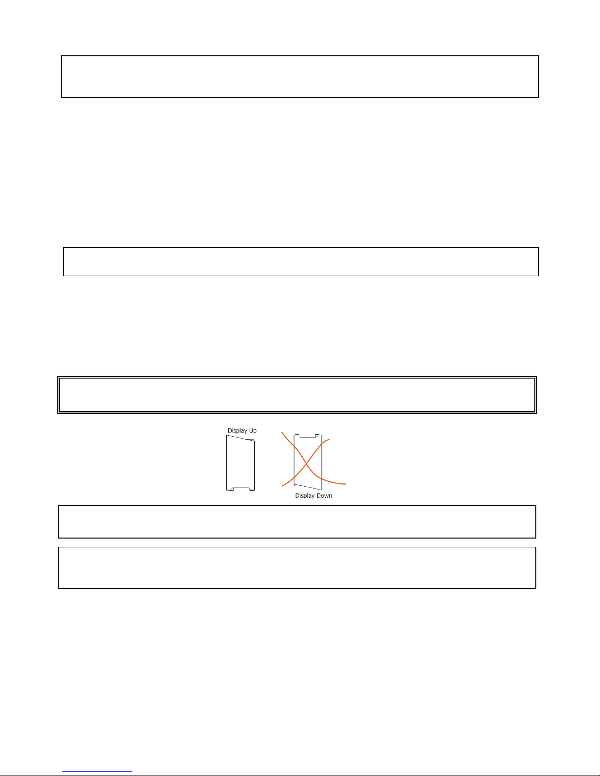
Do not place the unit display down. Do not transport or store the flight case upside-down.
The charging flight case falls under protection class I. Therefore this flight case has to be connected to a mains
socket outlet with a protective earthing connection.
LED light emission. Risk of eye injury.
Do not look into the beam from a short distance without suitable protective eyewear.
Do not look at LEDs with magnifiers or similar optical instruments that may concentrate the light output.
Install units on a level, stable surface where they do not present a hazard of tripping or falling.
Avoid brute force when installing or operating the unit.
When choosing the installation spot, please make sure that the unit is not exposed to extreme heat or dust.
The unit must be properly ventilated when in use !
Avoid using the unit in locations subject to possible impacts.
Page 4

LiteWare HO2
4
Do not short battery positive terminal to case as this will cause irreparable damage of the unit.
Only connect the unit to the „Robe” charging system!
Before transportation of the LiteWare units in the charging case or keeping them for a longer time in the
charging case which is not connected to mains , switch the LiteWare units off.
Do not block the front LEDs with any object when the unit is under operation.
Only use a battery specified in the chapter „Technical specifications“. We can not guarantee changer compatibillity
with other batteries.
If the unit has been exposed to drastic temperature fluctuation (e.g. after transportation), do not switch it on
immediately. The arising condensation water might damage your device. Leave the device switched off until it has
reached room temperature.
Please consider that unauthorized modifications on the unit are forbidden due to safety reasons!
If used outside, the unit must be dried after use and before inserting into charging case.
Page 5
LiteWare HO2
5
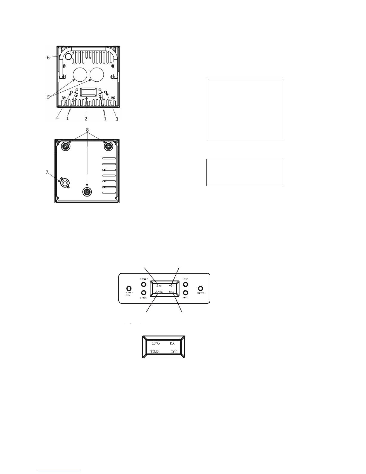
2. Fixture exterior view
3. Installation
3.1 Switching the LiteWare HO2 on
Press and hold the ON/OFF button for 3 seconds and the first screen will appear.
This screen blinks on a rota basic with the following screen which displayes battery capacity.
If DMX address flashes , the LiteWare does not receive DMX signal.
The LiteWare HO2 is equipped with 2-row LCD display which allows to set the fixture´s behaviour according to
your needs, obtain information on its operation, test its various parts and lastly program it, if it has to be used in a
stand-alone mode.
The six control buttons on the control panel have the following functions:
ESCAPE button-leaves menu without saving changes.
ENTER button- enters menu, confirms adjusted values and leaves menu.
Top side
1. Control buttons
2. Display
3. On/Off button
4. Unlink button
5. Lenses
6. Handle
Bottom side
7. Charging input
8. Rubber feets
Battery capacity 19%
WF signal level Symbol of linking to DMX transmitter
Selected DMX mode DMX address
Page 6

LiteWare HO2
6
PREV and - NEXT buttons - move between menu items on the same level, sets values.
Use the PREV/NEXT buttons to scroll through the various menu items. To select desired item, press the ENTER.
ON/OFF button – switches on and off the LiteWare. Press and hold the button for 3 seconds.
Wireless DMX button – unlinks the device from a wireless DMX transmitter.
3.2 Low battery
When the battery voltage becomes too low (10.8V and below), the battery base unit goes to sleep and light output
is closed.
You must recharge the battery base unit before you can use it again.
3.3 Flight case charger system
Warning!
Do not lay the flight case during charging the LiteWare units.
The flight case has to be open during charging the LiteWare units as warm is generated.
1. Ensure that the flight case is plugged into a mains supply with the supplied mains lead.
2. Place the LiteWare HO2 into the flight case. Do not cover the flight case.
During battery charging, the display on the battery base shows level of battery charging. By pressing the
PREV or NEXT button you can see the battery voltage, charging current and another data. When the battery
is fully charged, the message “CHARGED“ will appear.
3.4 Battery care
The LiteWare HO2 contains a sealed (GEL) lead-acid battery. The battery should not be left in a
discharged state for long periods because this will reduce its capacity. We recommend leaving the LiteWare HO2
on charge permanently when not in use.
The following points should help maintain the long life of your LiteWare battery:
• When in use, the LiteWare HO2 automatically switches off when the battery voltage reaches a set lower
limit. This is to avoid any deep discharge damage of the battery. It is not recommended that LiteWare batteries be
left for any prolonged period in this state. Discharging the battery under 70% accelerates its aging process.
• The LiteWare HO2 should always be fully re-charged as soon as possible. Once fully charged LiteWare HO2 can be
stored.
• If the LiteWare HO2 is to be unused for long periods, we recommend the LiteWare HO2 is charged every two
months to keep the batteries topped up.
• From market data, the estimated number of uses in a normal environment is around 200 cycles.
This may be higher if the LiteWare HO2 is not run to ‘turning off automatically’ every time. We recommend
replacing LiteWare battery every two years.
• Do not disconnect the LiteWare unit from the charging case before reaching 90% of the battery capacity.
Page 7

LiteWare HO2
7
3.5 Wireless DMX operation
All fixture channels are controlled by the wireless DMX controller that you use with the the LiteWare HO2.
The fixture allows to set 2 DMX modes:
Mode 1: 9 control channels
Mode 2: 4 control channels
To link the fixture with DMX transmitter.
The fixture can be only linked with the transmitter by running the link procedure at DMX transmitter .
After linking , the level of DMX signal ( 0-100 %) is displayed in the menu item “Signal“ (Special -->Vireless ->Signal).
To unlink the fixture from DMX transmitter.
The fixture can be unlinked from transmitter by means of the Wireless DMX button or using menu item “Unlink”
(Special -->Vireless -->Unlink or DMX --> Vireless -->Unlink ).
Page 8
LiteWare HO2
8
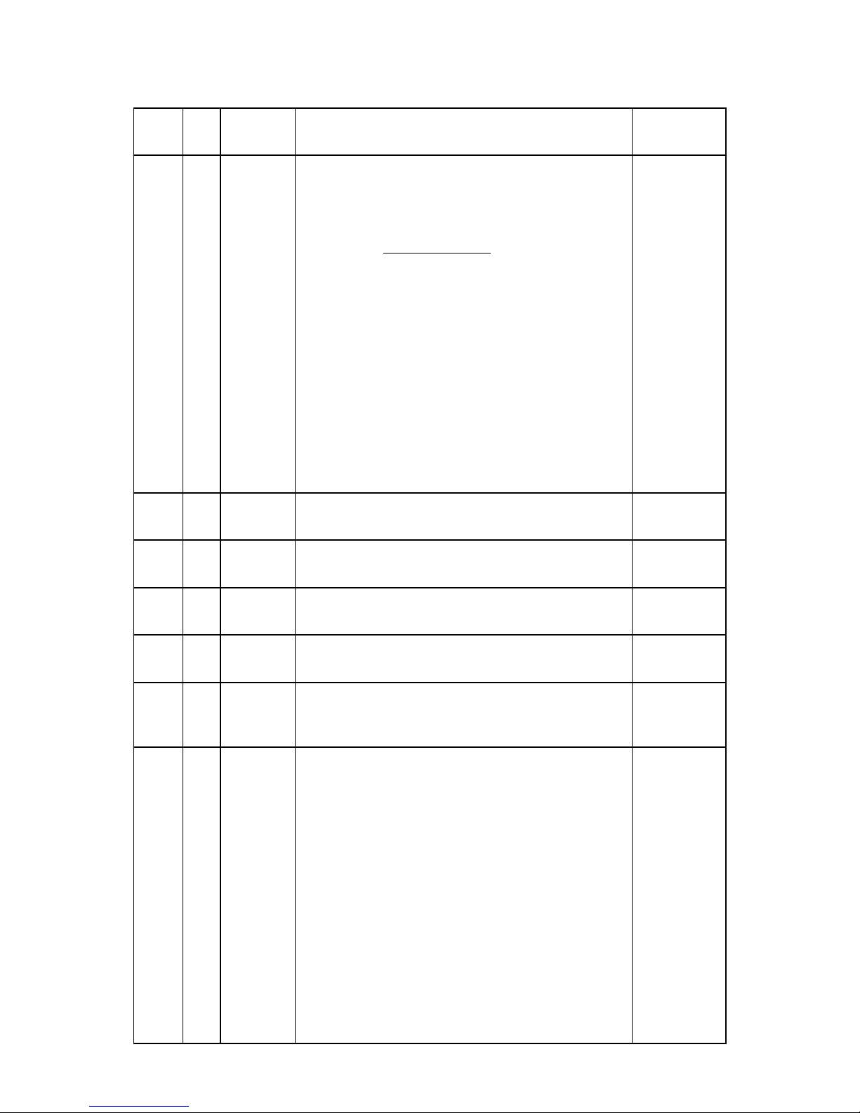
4. LiteWare HO2 - DMX protocol (
ver. 1.1
)
Mode 1 Mode 2
DMX
Value
Function
Type of
control
1 -
0-29
30-39
40-49
50-59
60-69
70-79
80-89
90-99
100-109
110-114
115-119
120-129
130-139
140-255
Special functions
Reserved
To activate following functions, stop in DMX value for at least 3 sec.
and shutter must be closed at least 3 sec. (Shutter channel 8 must
be at range of 0-31 DMX). Corresponding menu items are temporily
overrided except Acoustic alarm On/Off function.
RGBW colour mixing mode
CMY colour mixing mode
Acoustic alarm On
Acoustic alarm Off
Display permanent lits
Display permanent turned off
Dimmer curve: linear
Dimmer curve: square law
Colour calibration mode On
Colour calibration mode Off
Load: Eco
Load: Full
Reserved
step
step
step
step
step
step
step
step
step
step
step
step
step
2 1
0-255
Red (Cyan)
Red LEDs saturation control (0-100%)
proportional
3 2
0-255
Green
(Magenta)
Green LEDs saturation control (0-100%)
proportional
4 3
0-255
Blue (Yellow)
Blue LEDs saturation control (0-100%)
proportional
5 4
0-255
White
(RGBW mode only)
White LEDs saturation control (0-100%)
proportional
6 -
0
1-255
CT0
No function
Colour temperature correction
step
proportional
7 -
0
1-2
3
4-5
6
7-9
10-12
13-15
16
17-55
56
57 - 95
96
97 – 134
135
Virtual colour wheel
No function
White 2700 K
White 2700 K (tungsten emulation)*
White 3200 K
White 3200 K (tungsten emulation)*
White 4200 K
White 5600 K
White 8000 K
Blue (Blue=full, Red+Green+White=0)
Red=0, Greenup,Blue =full, White=0
Light Blue
(Red=0, Green=full, Blue =full, white=0)
Red=0, Green=full, Bluedown, White=0
Green (Red=0, Green=full, Blue =0, White=0)
Redup, Green=full, Blue=0, White=0
Yellow
(Red=full, Green=full, Blue=0,White=0)
step
step
step
step
step
step
step
step
step
proportional
step
proportional
step
proportional
step
Page 9

LiteWare HO2
9
136 -
174
175
176 -214
215
216-246
247
248
249
250-255
Red=full, Green
down, Blue=0, White=0
Red(Red=full, Green=0, Blue=0, White=0)
Red=full, Green=0, Blueup, White=0
Magenta
(
Red=full, Green=0,Blue=full,White=0)
Reddown, Green=0, Blue=full, White=0
Blue (Red=0, Green=0, Blue=full, White=0)
Rainbow effect( with fade time)
Rainbow effect(without fade time)
Reserved
proportional
step
proportional
step
proportional
step
step
step
8 -
0-31
32-63
64-95
96-127
128-143
144-159
160-191
192-223
224-255
Shutter/ Strobe
Shutter closed
Shutter open
Strobe-effect from slow to fast
Shutter open
Opening pulses in sequences slow--> fast
Closing pulses in sequences fast --> slow
Shutter open
Random strobe-effects from slow to fast
Shutter open
step
step
proportional
step
proportional
proportional
step
proportional
step
9 -
0 - 255
Dimmer
Dimmer intensity from 0% to 100%
proportional
*Halogen lamp effect during dimming
Page 10

LiteWare HO2
10
5. Control menu map
Default settings=Bold print
Menu Level 1
Menu Level 2
Menu Level 3
Menu Level 4
Menu Level 5
Menu Level 6
DMX
Set DMX
001-512
DMX
Pres.
Mode 1, Mode 2
Wireless
Signal
Unlink
InFo POn. Time
Total
Reset
DM.In.
Spec.
0-
255
:
Dimmer
0-
255
Temp.
Current
Led
Board
Board 2
Highest
Led
Board
Board 2
High Res
Led
Board
Board 2
Battery
Capacity (%)
Voltage (V)
Current (mA)
Temp (°C)
Tot. Cap. (Ah)
Case Ver
Spec. F. State
Sw Ver.
IC1
IC2
Page 11

LiteWare HO2
11
Menu Level 1
Menu Level 2
Menu Level 3
Menu Level 4
Menu Level 5
Menu Level 6
PErS DMX
Pres.
Mode 1
Mode 2
Alarm
Setting
ENT. PASW.
1-
255
Alarm On/Off
On,
Off
Sensitivity
0…13
…15
M. F.Time
0..0.8…25.5
Dimmer
Square Law
Linear
Display
On/Off T
On,
Off
Contrast
0-
100%
Bcklight
0-
100%
Load
full
eco
Col. cal. mod.
On, Off
Col.
mix
. mod.
RGBW
, CMY
Temp. Uni.
°C, °F
Aut. Off
Off
0.1h-25.5h
I. EF. Pos.
Spec.
0-
255
:
Dimmer
0-
255
Store
Defaults
M
anual
Spec.
:
Dimmer
Test Prg
St
a. Alone
Auto
Run Off
Page 12

LiteWare HO2
12
Menu Level 1
Menu Level 2
Menu Level 3
Menu Level 4
Menu Level 5
Menu Level 6
Test
Prog 1
:
Prog 3
Pr. Play Test Prg
Prog 3
Pr.
Edit P
rog 1 Step
.01 Prg. En.
1-40
: : Spec.
0-255
Prog.3 Step.40 : :
S. T
im. 0-25.5
s
F. Tim
0-
25.5
s
Copy
S
pecial
rdM Low
rdM H
igh
Wireless
Signal
Unlink
Hold DMX
On, Off
Battery init
Start
No
Yes
Change password
OLD PASSW
1-
255
NEW PASSW
1-
255
CON. PASSW
1-
255
Adjust
DMX Val.
Spec.
0-
255
:
Dimmer
0-
255
Cal. Col.
.
Ready C.
Red C.
0-
255
Grn C.
0-
255
Blu C.
0-
255
Whi C.
0-
255
Store
Page 13

LiteWare HO2
13
Menu Level 1
Menu Level 2
Menu Level 3
Menu Level 4
Menu
Level 5
Menu Level 6
Cal.temp
C. 2700K
Red
:
Green
C. 8000K
Blue
White
Cal. Def.
No
Yes
Case SW Upd
6. Fixture menu
6.1 Fixture Address
Use this menu to set the DMX address and DMX mode of the fixture.
Set DMX --- Set DMX address. Select this submenu to set a DMX start address.
To set a DMX address.
1. Use the PREV/NEXT buttons to find “Set DMX“.
2. Press the ENTER button.
3. Use the PREV/NEXT buttons to select desired start address.
4. Press the ENTER button to confirm the choice.
DMX Pres --- DMX preset. Select this menu item to set a desired DMX mode. Please refer to the chapter "DMX
protocol" for detail description of each DMX mode.
Note: After switching on, the LiteWare HO2 will automatically detect whether DMX 512 data is received or not.
If there is no data received at the DMX input, the display will start to flash with actually set address.
Wireless --- Signal – The item serves for reading of the level of DMX signal.
Unlink
-
The item serves for unlinking the fixture from the transmitter.
6.2 Fixture information
Use this menu to read useful information about the fixture status.
To display desired information.
1. Use the PREV/NEXT buttons to find the “ InFo“ menu.
2. Press the ENTER button.
3. Use the PREV/NEXT buttons to select the required menu item.
4. Press the ENTER button to confirm the choice.
Pon Time
---Power On Time. Use the menu item to read the number of operation hours of the fixture.
Page 14

LiteWare HO2
14
Total - the function shows the total number of the operation hours since the LiteWare HO2 has
been fabricated.
Reset - the function shows the number of the operation hours that the LiteWare HO2 has been
powered on since the counter was last reset.
In order to reset this counter to 0 you have to press the ENTER button, then by means of the PREV
and NEXT buttons select “Yes”and press the ENTER button again.
DM In ---DMX values. Select this function to read DMX values of each channel received by the fixture.
Temp ---Fixture Temperatures. Select this menu to read the temperature of the fixture:
Current - the current temperature of the fixture inside.
Highest - the menu item shows the max. temperatures of the fixture inside since
the LiteWare HO2 has been fabricated.
High Res. - the menu item shows the maximum temperatures of the fixture inside since
the counter was last reset. In order to reset this counter, you have to press the ENTER button,
then by means of the PREV and NEXT buttons select “Yes”and press the ENTER button again.
Measuring points: Led - temperature on the PCB with LEDs.
Board – first temperature on the PCB of the control electronic.
Board 2- second temperature on the PCB of the control electronic.
The temperatures can be displayed in either °C or °F units - see option “Temp. Uni.“ in the menu “Pers“.
Spec. F. State ---Special function stare. The menu item shows current state of switching functions on DMX channel
1.
Battery ---Battery information. Select this menu to read the battery state.
Capacity - capacity of the battery in %. Fully charged battery shows 100%.
Note: in the Full mode, the LiteWare unit can be switched off automatically when capacity has
fallen under 13%.
Voltage – voltage of the battery in V.
Current – current of the battery in mA. Symbol “–“ means discharging, “+” means charging.
Temp – temperature of the electronic controlling the battery.
Tot. Cap. – Total capacity of the battery in Ah.
Case Ver. – Software version of the charging case.
Sw Ver ---Software Version. Select this function to read the software version of the LiteWare unit.
6.3 Personality
Use this menu to modify the LiteWare HO2 operating behaviour.
DMX Pres --- DMX preset. Select this menu item to set a desired DMX mode. Please refer to the chapter "DMX
protocol" for detail description of each DMX mode.
Alarm Setting --- Acoustic alarm . If this alarm is on, the sensor signalizes unwanted relocation of the LiteWare
unit.
After final placing, switch the acoustic alarm on (you can also use DMX command – see DMX chart, channel
“Special function”. Do not forget to switch the sensor off prior to manipulate with the LiteWare units!
To switch the acoustic alarm on:
1. Enter the “Alarm” menu.
2. Enter the password (default password is “001”) using the PREV/NEXT buttons and confirm with the ENTER
button .
Page 15

LiteWare HO2
15
3. Use the PREV/NEXT buttons to select menu item “ Alarm On/Off”, press the ENTER button and select
option “On” ( if you want to deactivate the acoustic alarm, select option “Off”) and confirm with the
ENTER button.
The menu item “Sensitiv” allows to set desired sensitivity (0-min. sensitivity, 15 max. sensitivity) of the acoustic
alarm sensor. This sensitivity can be affected by material on which the LiteWare unit stands.
Note: the acoustic alarm is automatically set off if:
- the LiteWare unit is inserted into charging case, which is conected to mains.
- the LiteWare unit is 25.5 hours in a sleep mode (without action) out of the charging case or in the
charging case which is not connected to mains.
M. F. Time --- Max. fade time. Select this menu item to set a desired max. fade time (0-25.5 sec.). This adjusted
fade time influences fade of R,G,B,W and dimmer during DMX operation:
If time between two receiving DMX values is > than the fade time set in the item “M Ftime“, the entire adjusted
fade time will be used.
If time between two receiving DMX values is < than the fade time set in the item“M Ftime“, the adjusted fade time
will be reduced to fill entire time between the two receiving DMX values.
e.g “M Ftime“=2sec. and fixture has received Red=0 DMX, after 5 seconds will receive Red=255 DMX. It means, that
red will go to full intensity during 2 seconds.
“M Ftime“=8 sec. and fixture has received Red=0 DMX, after 5 seconds will receive Red=255 DMX. It means, that
red will go to full intensity during 5 seconds (max. fade time is reduced from 8 sec. to 5 sec.).
Dimmer --- Dimmer curve. The menu item allows to select dimmer curve: Linear or Square Law.
Display. --- Display adjusting. This function allows you to change the display settings.
On/Off T
-
This function allows you to keep the display permanent on or turn it off two seconds
after last pressing any button on the control panel.The function is also available on the channel 1
(DMX range of 70-89).
Contrast
-
Use this function to adjust contrast of the display (0-100%).
Bcklight
-
Use this function to adjust backlight of the display (0-100%).
Load --- LEDs power. The menu allows to set two modes of LEDs power.
full
–
max. power of LEDs (500mA LED current), max light output
.
eco –
economic mode (350mA LED current), longer operation time of the LiteWare unit.
Col. cal. Mod. - Colour calibration mode. If the functin is on, the white output (2700K-8000K) from the fixture (and
also mixed colours) is more uniform,. Each colour is dynamically corrected according to the value set in the menu
"Cal Col." and “Cal Temp”. (Special-> Adjust-> Cal. Col.).
Note: If colour calibration mode is on, the colour temperature of full RGBW (R+G+B+W=255DMX) is 8000K.
Col. mix. Mod. - Colour mixing mode. This item allows switching into RGBW or CMY mode. In the CMY mode, the
white channel is not active.
Temp. Uni. --- Temperature Unit. Use this menu in order to display the fixture temperatures in desired units: °C or
°F.
Aut Off. – Automatic switching off. The function allows to switch the LiteWare unit off automatically if DMX signal
is missing. The time period after that the unit will be switched off can be set from 0.1hour to 25.5 hours.
I. Ef. Pos --- Init effect positions. Use this function to set all effects to the desired positions to which they will move
after switching the fixture on (if DMX is not being received).
Defaults
--- Default Settings.The menu item sets fixture parameters to the default (factory) values except menu
items “Alarm Setting” and “Change Password” (from menu Special).
Page 16

LiteWare HO2
16
6.4 Manual mode
Use this menu for control the fixture without connected DMX console.
To control fixture channels.
4. Use the PREV/NEXT buttons to find “ Manual“ menu.
5. Press the ENTER button.
6. Use the PREV/NEXT buttons to select desired effect (channel).
List of control channels:
“Spec.” – special functions
“Red” - red LEDs saturations
“Green“ - green LEDs saturations
“Blue“ - blue LEDs saturations
“White“ - white LEDs saturations
“C TC“ - a colour temperature correction
“C Wheel“ - a virtual colour wheel
“Strobe“- a strobe, shutter
“Dimmer“- a dimmer
7. Press the ENTER button and use the PREV/NEXT buttons to set value , press the ENTER button to confirm it.
Note: the switching functions as a colour mixing mode, acoustic allarm and colour calibration mode cannot be
controlled from this menu, use the menu “Personality” for changing their settings.
6.5 Test program
Use this menu to run demo-test sequences without an external controller, which will show you some possibilities
of using the LiteWare HO2.
6.6 Stand-alone setting
The fixtures on a data link are not connected to the controller but can execute pre-set programs which can be
different for every fixture.
Auto Run --- Automatic playback. This function allows you to select the program which will be played after
switching the fixture on. Selected program will be played continuously in a loop.
1. Use the PREV/NEXT buttons to find “ Sta Alone“ menu.
2. Press the ENTER button.
3. Use the PREV/NEXT buttons to select “ Auto Run“ item.
4. Press the ENTER button.
5. Use the PREV/NEXT buttons to select desired program.
6. Press the ENTER button to confirm the choice.
Pr. Play --- Playing program. By enter to this menu a complete overview of all programs is offered, from which the
program to be run can be selected.
1. Use the PREV/NEXT buttons to find “Pr. Play“ menu.
2. Press the ENTER button.
3. Use the PREV/NEXT buttons to select desired program.
4. Press the ENTER button. The selected program runs in a loop.
Pr. Edit
--- Editing a program. The fixture offers 3 freely editable programs (Prog.1-Prog.3) each up to 40 steps.
Every program step includes a fade time-the time taken by the step´s channel status to reach the desired level and
a step time-the total time occupied by the step in the program.
Page 17

LiteWare HO2
17
E.g. If “F.tim.“=5 second and “S.tim.“=20 second, effects will go to the desired position during 5 seconds and after
that they will stay in this position for 15 seconds before going to the next prog. step
1. 1. Use the PREV/NEXT buttons to find “ Sta Alone“ menu and press the ENTER button.
2. Use the PREV/NEXT buttons to select “Pr. Edit“ menu and press the ENTER button.
3. Use the PREV/NEXT buttons to select a program you want to edit (Prog.1-Prog.3) and press ENTER button.
4. Use the PREV/NEXT buttons to select a desired program step ("Step 01" - "Step 40") and press ENTER
button.
5. Use the PREV/NEXT buttons to select a channel you want to edit and press the ENTER button.
List of editable items:
“Prg.En” - a number of last program step (value 1-40). This value should be set before start
programming (e.g. if you want to create program with 10 steps, set Prg.En=10).
“Spec.” – special functions
“Red” - red LEDs saturations
“Green“ - green LEDs saturations
“Blue“ - blue LEDs saturations
“White“ - white LEDs saturations
“C TC“ - a colour temperature correction
“C Wheel“ - a virtual colour wheel
“Strobe“- a strobe, shutter
“Dimmer“- a dimmer
“F.tim.“- a fade time, (0-25.5) seconds
“S.tim.“ - step time, value (0-25.5) seconds
“COPY“. – this item duplicates the current prog. step to the next prog. step. The item “Prg En” is increased
automatically.
6. Use the PREV/NEXT buttons to set a DMX value of the channel and then press the ENTER button.
7. Use the PREV/NEXT buttons to select next channel and press the ENTER button.
8. After having set all channels in the current program step, press the MODE button to go by one menu level
back and select another program step.
6.7 Special functions
rdM Low --- RDM Code.This menu item shows the first part of the RDM identification code.
rdM High --- RDM Code. This menu item shows the second part of the RDM identification code.
Wireless --- Signal – The item serves for reading of the level of DMX signal.
Unlink
-
The item serves for unlinking the fixture from the transmitter.
HoLd DMX --- If the function is on, the last received DMX values are held in case, that DMX data receiving was
interrupted (e.g. disconnected DMX controller).
Change password --- Use the munu to change your password. The password is required if you need to enter the
menu “Alarm”. Factory default password is “001”.
To change password.
1. Enter the “Change password” menu.
2. Enter the old password using the PREV/NEXT buttons and confirm with the ENTER button .
3. Set the new password using the PREV/NEXT buttons and confirm with the ENTER button. As password you
have to select one number from range 1-255.
4. Repeat the new password.
Page 18

LiteWare HO2
18
Note: when you enter old password menu, the sign “000” is displayed although some number was set.
Battery init ---Battery initialization. Use this function in a special case, e.g. after changing the battery.
The battery initialization runs in two steps (charging and discharging). When you select “Yes”, and go to the first
screen of the display, the sign “ Battery Init St1” appears on a rota basic with the first screen. Place the LiteWare
unit into charging case (connected to mains) until the battery is fully charged (message “CHARGED“ is displayed).
Place the LiteWare unit outside the case and switch the display on. The display shows “ Battery Init St2” on a rota
basic with the first screen and the unit lights. Let the battery discharge until light output is closed. Do not interrupt
this action. During this step, DMX control and charging of the unit is disabled.
When the battery is discharged, the battery initialization is completed.
After charging the battery, the LiteWare unit is prepared for operation.
Note: during the battery initialization process, the LiteWare unit has to be switched into eco mode.
Adjust - Adjustment. The menu allows the fine adjustment of colours.
DMX Val- DMX values. Use the menu to set DMX values of fixture´s channels.
Cal Col - A calibration o red, green, blue and white colours by means of an automatic calibration
with a factory equipment.
Ready C. – when this item is displayed, the LiteWare unit stops receiving wireless DMX
signal and starts receiving wired DMX via 3-pin XLR (charging connector).
Red C – red LEDs saturation (0-255)
Grn C – green LEDs saturation (0-255)
Blu C – blue LEDs saturation (0-255)
Whi C – white LEDs saturation (0-255)
Store – saves adjusted values
Cal Temp – Selection of colour temperature for manual calibration: 2700K, 3200K, 4200K, 5600K,
8000K.
Manual colour calibration:
1. Switch the fixture on, set full mode (menu “Personality”), go to the menu “Manual” and set the
shutter,dimmer, red, green, blue and white channel at 255DMX, aim the beam at wall in distance cca 5m
and let the fixture heat up.
2. Go to the “Manual” menu and set the C Wheel at 1 DMX (2700K)
3. Go to the “Cal temp” menu, select “2700K” item and by means of the Red , Green, Blue and White items
adjust the 2700K colour temperature as exactly as possible (∆u´v´= 0).
After calibration, press the “Store“ item to save adjusted values.
4. Go to the “Manual” menu and set the C Wheel at 4 DMX (3200K).
5. Go to the “Cal Temp” menu, select “3200K” item and by means of the Red , Green , Blue and White items
adjust the 3200K colour temperature as exactly as possible (∆u´v´= 0).
After calibration, press the “Store“ item to save adjusted values.
6. Repeat this procedure for rest of colour temperatures (4200K, 5600K, 8000K).
7. Software update
The following are required in order to update software in the LiteWare unit or charging case:
- PC running Windows XP/Vista/7/8 /Linux/OSX with connection to the Internet
- ROBE RDM Uploader
- Robe Universal Interface WTX (RUNIT WTX)
Note: Both software update and case software update should execute a qualified person. If you lack qualification,
do not attempt the update yourself and ask for help your ROBE distributor.
Before starting both updates, the LiteWare unit has to be charged!
Note: programs 1-3 and all items in the menu "PErS" and “Special” will be set to their default values (except menu
“Alarm Setting”) after software update.
Page 19

LiteWare HO2
19
To update software in the LiteWare unit
NOTE: The Liteware unit must not be in charging case during software update.
I. Installation of the ROBE RDM Uploader.
1. ROBE RDM Uploader is available from the ROBE web site at WWW.robe.cz.
2. Make a new directory ( e.g. Robe_Uploader) on your hard disk and download the software into it.
3. Install the software on your computer.
II.Fixture software updating.
1. Connect your PC with the USB input of the RUNIT WTX.
Turn both the computer and the LiteWare unit on (shutter should be closed).
We recommend to cancel all running programs before starting the ROBE RDM Uploader.
2. Run the ROBE RDM Uploader and perform software update of the LiteWare unit.
Avoid interrupting the update process.
To update software in the charging case
Install the RUNIT WTX and the ROBE RDM Uploader software as described above.
Note: The charging case has to be empty before case software update.
1 Take one charged LiteWare unit outside the case and switch it on (shutter has to be closed).
2 Use the PREV/NEXT buttons to find “Special“ menu.
3 Press the ENTER button.
4 Use the PREV/NEXT buttons to find “ Case SW Upd“ item. Press the ENTER button.
5 The notice “ In case? no“ will appear.
6 Insert the LiteWare unit into case.
7 Use the PREV/NEXT buttons to select “yes” item, confirm by pressing the ENTER button.
8 The sign “ wait“ will appear.
9 Run the ROBE RDM Uploader and perform software update of the charging case.
It may last several minutes to perform software update.
8. RDM
This fixture is ready for RDM operation.RDM (Remote Device Management) is a bi-directional communications
protocol for use in DMX512 control systems, it is the new open standard for DMX512 device configuration and
status monitoring.
The RDM protocol allows data packets to be inserted into a DMX512 data stream without adversely affecting
existing non-RDM equipment. By using a special „Start Code,“ and by complying with the timing specifications for
DMX512, the RDM protocol allows a console or dedicated RDM controller to send commands to and receive
messages from specific moving lights.
RDM allows explicit commands to be sent to a device and responses to be received from it.
The list of commands for LiteWare HO2 is the following.
Page 20

LiteWare HO2
20
Parameter ID Discovery command SET command GET command
DISC_UNIQUE_BRANCH *
DISC_MUTE *
DISC_UN_MUTE *
DEVICE_INFO
*
SUPPORTED_PARAMETERS
*
SOFTWARE_VERSION_LABEL
*
DMX_START_ADDRESS
* *
IDENTIFY_DEVICE
* *
DEVICE_MODEL_DESCRIPTION
*
MANUFACTURER_LABEL
*
DEVICE_LABEL
* *
SENSOR_DEFINITION
*
SENSOR_VALUE
*
DISPLAY_LEVEL
* *
DEVICE_RESET
*
DMX_PERSONALITY
* *
DMX_PERSONALITY_DESCRIPTION
*
STATUS_MESSAGES
*
STATUS_ID_DESCRIPTION
*
DEVICE_HOURS
*
9. Information and error messages
CHARGED – the LiteWare is fully charged and ready for operation.
CHARGE NOW – the battery of the LiteWare is discharged and has to be placed to the flight case in order
to charge it.
CHECK BATTERY – run the “Battery init“ procedure from the menu Special.
Page 21

LiteWare HO2
21
10. Technical specifications
Power supply
• Battery supply
• flight case charger system
Optic & Effects
• Light source:
2 x high power RGBW multichip
• Optical system: 22°
• RGBW or CMY colour mixing
• Virtual colour wheel with preset whites (2700K, 3200K, 4200K, 5600K, 8000K)
• Adjustable strobe sequences
Control
• 2-row LCD display & 4 control buttons + 2 function buttons (On/Off, Unlink)
• Control: USITT DMX 512 (RDM support)
• DMX protocol modes: 2 (4, 9 control channels)
• Operations modes: Wireless DMX, Stand-alone
• Two LED load modes: eco and full
• Manual control of all effects via control panel
• 3 user editable programs each up to 40 steps
Wireless DMX/RDM module
• Compliance with USITT DMX-512 (1986 & 1990) and 512-A
• Full DMX fidelity and frame integrity
• Auto sensing of DMX frame rate and frame size
<5ms DMX latency
• Operational frequency range of 2402-2480 MHz
• Producer: LumenRadio
Strobe
• Strobe effect with variable speed
• Pre-programmed random strobe pulse-effects
Dimmer
• Smooth dimmer from 0 - 100 %
Connection
• Charging input: 3-pin XLR (male)
Battery
• GEL OGiV 12260 L
Runtime from fully charged battery
RGB/RGBW full
Two colours full
One colour full
Full mode
5 16 23
Eco mode
8 24 34
These are representative values measured with new battery, actual values will vary slightly due to the battery aging process.
Charging cycle
• Approximately 11 hours
Ambient operating temperature range
• -15°C ~ 40° C
Page 22

LiteWare HO2
22
Battery capacity decreases from its nominal capacity when it is operated below nominal operating
temperature (25°C).
Capacity affected by
temperature (20hr)
40°C 100%
25°C 100%
0°C 86%
-
15°C 65%
Dimensions (mm)
Weight
• 15 kg
Ingress protection
• IP 45
Charging flight case
• weight: 45 kg (empty)
• dimensions (W x L x H): 500mm x 735mm x775mm
• Input voltage: 100V-240V
• Max. power c
onsumption
: 320W
Included items
• 6 x LiteWare HO2
• 1 x Flight charging case
Page 23

LiteWare HO2
23
Light output
Page 24

LiteWare HO2
24
11. Cleaning and maintenance
Disconnect from the charging flight case before starting any cleaning or maintenance work
A soft lint-free wet cloth and a neutral soap is recommended for cleaning, under no circumstances should alcohol
or solvents be used!
Maintenance and service operations are only to be carried out by a qualified person.
If you remove the battery, please observe the correct polarity upon reconnection.
Should you need any spare parts, please use genuine parts.
11.1 Disposing of the product
To preserve the environment please dispose or recycle this product at the end of its life according to the local
regulations and codes.
Specifications are subject to change without notice.
August 28, 2015
Page 25

LiteWare HO2
25
 Loading...