

Page 1
Preliminary version
Page 2

2
Table of contents
1. Safety instructions ....................................................................................3
1. Description.................................................................................................3
2. Installation..................................................................................................4
3. Technical specications............................................................................6
Page 3
3
FOR YOUR OWN SAFETY, PLEASE READ THIS USER MANUAL CAREFULLY
BEFORE YOU INSTALL THE PRODUCT .
1. Safety instructions
CAUTION!
This product was designed for indoor use only.
This device is for professional use only. It is not for household use.
This product has left our premises in absolutely perfect condition. In order to maintain this condition and to
ensure a safe operation, it is absolutely necessary for the user to follow the safety instructions and warning
notes written in this manual.
The manufacturer will not accept liability for any resulting damages caused by the non-observance of this
manual or any unauthorized modication to the product.
If the device has been exposed to drastic temperature uctuation (e.g. after transportation), do not switch it on
immediately. The arising condensation water might damage your device. Leave the device switched off until
it has reached room temperature.
The product never must be covered with cloth or other materials during operation.
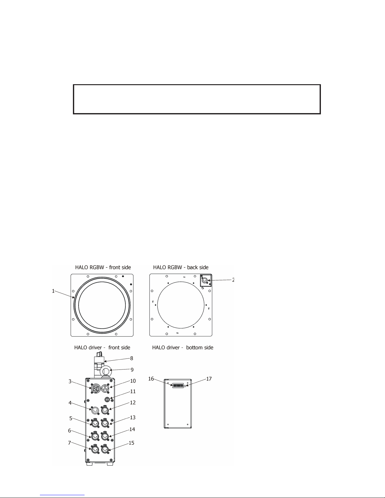
1. Description
The HALO RGB (W) is a LED ring mountable on a stage reector PAR 64.
The HALO Driver is a control unit for the Halo RGB (W). Up to 6 HALO RGB (W) units can be connected to
the HALO Driver.
1 - LED ring
2 - Control input
3 - Power OUT
4 - DMX IN
5 - LED port 1
6 - LED port 3
7 - LED port 5
8 - Clamp
9 - Safety attachment eyelet
10- Power IN
11- Fuse holder
12- DMX OUT
13- LED port 2
14- LED port 4
15- LED port 6
16- Dip switch
17 -Signal LED
Page 4
4
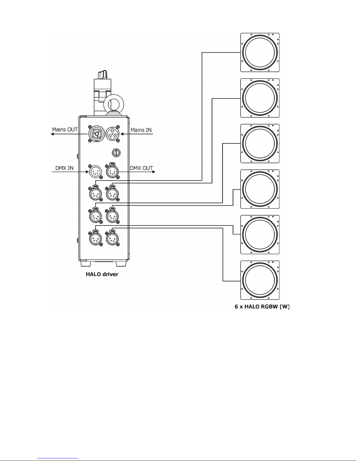
2. Installation
Design of the HALO Driver allows to connect several xtures to AC mains power in one interconnected daisy
chain using power input and throughput connectors.The max. number of connected xtures depends on the
AC mains power voltage and xture version:
EU version (CE) US version (cETLus)
10 xtures at power supply= 230V 6 xtures at power supply= 230V
9 xtures at power supply= 208V 5 xtures at power supply= 208V
5 xtures at power supply= 120V 3 xtures at power supply= 120V
Actual numbers of xtures may differ from values stated above as you have to take into account the length of
supply cables, circuit breaker etc. at projecting of the xtures installation Do not overload the supply line and
the connecting leads.
Wiring and connection work must be carried out by qualied staff!
The Halo Driver is equipped with the clamp for rigging on a truss. �or securing the HALO Driver to the truss,�or securing the HALO Driver to the truss,
install a safety wire that can hold at least 10 times the weight of the xture. Use only the safety wire with a snap
hook with screw lock gate. �asten the snap hook in the safety attachment eyelet and the safety wire around
the truss.
Page 5
5
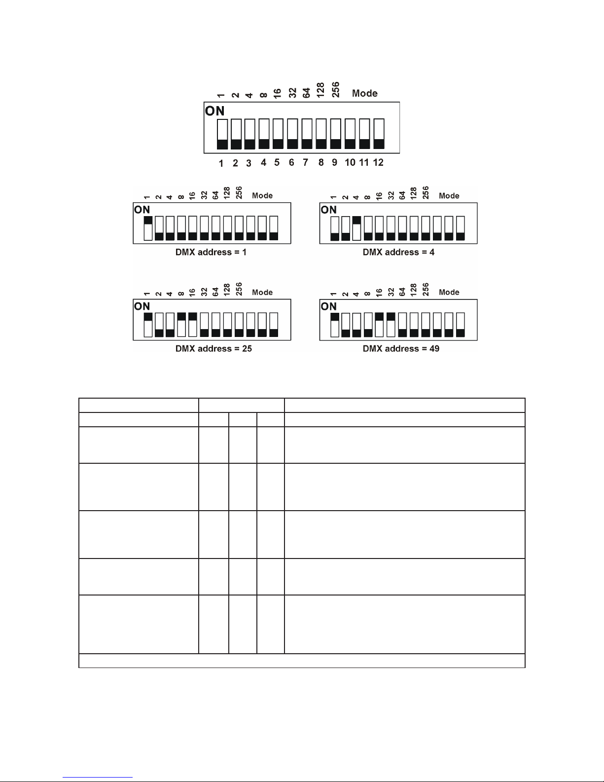
DMX start address setting
The DMX start address, is the rst channel used to receive instructions from the DMX controller. The address
may be any channel from 1 to 510 and is set on the Address DIP switch.
Examples
Control mode setting
The last three DIP switches dene control modes.
DIPs
Control Mode 10 11 12 Function
24 CH Intelli�lex Mode OFF OFF OFF Uses 24 Channel Personality to control each Halo Ring.
Uses Start Address for rst port as dened by DIP's19.
Each subsequent port is 24 channelsLater.
3 CH Strobe Mode ON OFF OFF Uses 3 Channel Strobe Personality to control each Halo
Ring.
Uses Start Address for rst port as dened by DIP's
19. Each subsequent port is 3 channels Later .
3 CH RGB Mode ON ON OFF Uses 3 Channel RGB Personality to control each Halo
Ring.
Uses Start Address for rst port as dened by DIP's
19. Each subsequent port is 3 channels Later .
Direct Mapping Mode OFF ON OFF Pixel Map each Halo Ring using 72 Channels.
Uses Start Address for rst port as dened by DIP's
19. Each subsequent port is 72 channels Later .
Intelli-Mappping Mode X X ON All 6 ports use the same 24 Channel Personality.
When Pixel Mapping Engine is active,it will work in a simi-
lar way to the direct mapping map, but will start the map
25 channels later that the start address (72 Channels per
Port).
X = position ignored
ALWAYS DISCONNECT THE HALO DRIVER FROM MAINS BEFORE SETTING THE DIP SWITCHES.
Page 6
6
3. Technical specications
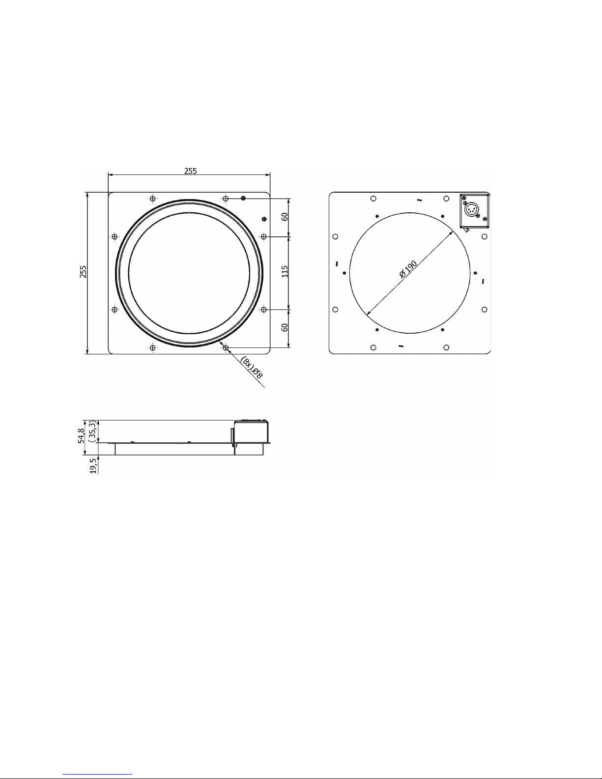
HALO RGB
Input voltage: 5V
Max. power consumption : 48W
Light source: 96 x RGB LEDs
Number of pixels: 24 (4 LEDs per pixel)
Control input: 4-pin XLR (male)
Ingress protection: IP 2X
Weight: 0.8 kg
Dimensions (mm):
Page 7

7
August 31, 2016
All Specications subject to change without notice
HALO Driver
Input voltage range: 100-240V, 50-60Hz
Max. power consumption : 330W@230V
�use: T 4A/250V ~
Mains input: 16A max. (CE ), 10A max. (cETLus)
Mains output: 15A max. (CE ), 9A max. (cETLus)
Control modes: 24 CH Intelli�lex mode (24 channels per port)
3 CH Strobe mode (3 channels per port)
3 CH RGB mode (3 channels per port)
Direct Mapping mode (72 channels per port)
Intelli-Mapping mode (96 channels per port)
LED ports: 6 (4-pin XLR -female)
DMX IN/OUT: 5-pin XLR (male/female)
Power IN: Neutrik NAC3MPX
Power OUT: Neutrik NAC3�PX
Ingress protection: IP2x
Weight: 3.8 kg
Dimensions:
Optional Accessories
(P/N 13051800) Connecting cable Halo 10m (4-pin XLR)
(P/N 1305 2439) Daisy Chain PowerCon TRUE1 In/Out, EU, 2m, indoor
(P/N 1305 2440) Daisy Chain PowerCon TRUE1 In/Out, US, 2m, indoor
(P/N 13052444) Daisy Chain PowerCon TRUE1 In/Out, EU, 5m, indoor
(P/N 1305 2405) Mains Cable PowerCon In TRUE1/Schuko, 2m, indoor
(P/N 1305 2406) Mains Cable PowerCon In TRUE1/US, 2m, indoor
(P/N 1305 2407) Mains Cable PowerCon In TRUE1/open ended, 2m, indoor
(P/N 13052443) Mains Cable PowerCon In TRUE1/Hubb 2321, 2m US, indoor
(P/N 13052445) Mains Cable PowerCon In TRUE1/CEE 16A, 2m, indoor
Safety wire
Installation wire
Page 8

HALO Driver - DMX protocol, version 1.0
DMX
Function
123456Value
125497397
121
Intensity
0 - 255 Intensity 0% -> 100%
proportional
226507498
122
Red 1 - Background or 2nd FX colour
0 - 255 Colour saturation control 0 ->100%
proportional
327517599
123
Green 1 - Background or 2nd FX colour
0 - 255 Colour saturation control 0 ->100%
proportional
4285276100
124
Blue 1 - Background or 2nd FX colour
0 - 255 Colour saturation control 0 ->100%
proportional
5295377101
125
Red 2 - Main FX colour
0 - 255 Colour saturation control 0 ->100%
proportional
6305478102
126
Green 2 - Main FX colour
0 - 255 Colour saturation control 0 ->100%
proportional
7315579103
127
Blue 2 - Main FX colour
0 - 255 Colour saturation control 0 ->100%
proportional
8325680104
128
FX Select
See table below
9335781105
129
Rotate
0 Off
step
1-126 Forwards Rotation (fast -> slow )
proportional
127 Pause rotate
step
128-255 Backwards Rotation (slow -> fast )
proportional
10345782106
130
Repeat
0 Full
step
1-63 x 2
step
64-127 x 4
step
128-195 x 8
step
196-254 x 16
step
255 x 32
step
11355983107
131
Direction
0-63
Forwards
step
64-127
Reverse
step
128-191
Mirror Out
step
192-255
Mirror In
step
12366084108
132
Rotate offset
0 - 255
Offsets start point of rotating effects over each port proportional
13376185109
133
Intensity
0 - 255 Intensity 0% -> 100%
proportional
14386286110
134
Red 1 - Background or 2nd FX colour
0 - 255 Colour saturation control 0 ->100%
proportional
15396387111
135
Green 1 - Background or 2nd FX colour
0 - 255 Colour saturation control 0 ->100%
proportional
16406488112
136
Blue 1 - Background or 2nd FX colour
0 - 255 Colour saturation control 0 ->100%
proportional
17416589113
137
Red 2 - Main FX colour
24 CH IntelliFlex Mode
Type of
control
Layer 1
Port/Channel
Layer 2
Page 9

DMX
Function
123456Value
Type of
control
Port/Channel
0 - 255 Colour saturation control 0 ->100%
proportional
18426690114
138
Green 2 - Main FX colour
0 - 255 Colour saturation control 0 ->100%
proportional
19436791115
139
Blue 2 - Main FX colour
0 - 255 Colour saturation control 0 ->100%
proportional
20446892116
140
FX Select
See table below
21456993117
141
Rotate
0 Off
step
1-126 Forwards Rotation (fast -> slow )
proportional
127 Pause rotate
step
128-255 Backwards Rotation (slow -> fast)
proportional
22467094118
142
Repeat
0 Full
step
1-63 x 2
step
64-127 x 4
step
128-195 x 8
step
196-254 x 16
step
255 x 32
step
23477195119
143
Direction
0-63 Forwards
step
64-127 Reverse
step
128-191 Mirror Out
step
192-255 Mirror In
step
24487296120
144
Rotate offset
0 - 255
Offsets start point of rotating effects over each port proportional
DMX
Function
123456Value
8/20 32/44 56/68 80/92 104/116 128/140
FX Select
0
Off
step
One colour Paparazzi-Snap
1 Example Effect
step
2 Slow- low density
step
3 Slow - medium density
step
4 Slow - high density
step
5 Slow - linear
step
6 Medium - low density
step
7 Medium - medium density
step
8 Medium - high density
step
9 Medium - linear
step
10 Fast - low density
step
11 Fast- medium density
step
12 Fast - high density
step
13 Fast - linear
step
One colour Paparazzi-Fade
14 Example Effect
step
Port/Channel
Type of
control
Page 10

DMX
Function
123456Value
Type of
control
Port/Channel
15 Slow- low density
step
16 Slow - medium density
step
17 Slow - high density
step
18 Slow - linear
step
19 Medium - low density
step
20 Medium - medium density
step
21 Medium - high density
step
22 Medium - linear
step
23 Fast - low density
step
24 Fast- medium density
step
25 Fast - high density
step
26 Fast - linear
step
Two colour Paparazzi-Snap
27 Example Effect
step
28 Slow- low density
step
29 Slow - medium density
step
30 Slow - high density
step
31 Slow - linear
step
32 Medium - low density
step
33 Medium - medium density
step
34 Medium - high density
step
35 Medium - linear
step
36 Fast - low density
step
37 Fast- medium density
step
38 Fast - high density
step
39 Fast - linear
step
Two colour Paparazzi-Fade
40 Example Effect
step
41 Slow- low density
step
42 Slow - medium density
step
43 Slow - high density
step
44 Slow - linear
step
45 Medium - low density
step
46 Medium - medium density
step
47 Medium - high density
step
48 Medium - linear
step
49 Fast - low density
step
50 Fast- medium density
step
51 Fast - high density
step
52 Fast - linear
step
Trace 1-Uniform Decay
53 Example Effect
step
54 Slow - short tail
step
55 Slow - medium tail
step
56 Slow- long tail
step
57 Medium -short tail
step
58 Medium - medium tail
step
59 Medium - long tail
step
Page 11

DMX
Function
123456Value
Type of
control
Port/Channel
60 Fast - short tail
step
61 Fast - medium tail
step
62 Fast - long tail
step
Trace 2-Uniform Decay (colour mix with base)
63 Example Effect
step
64 Slow - short tail
step
65 Slow - medium tail
step
66 Slow- long tail
step
67 Medium -short tail
step
68 Medium - medium tail
step
69 Medium - long tail
step
70 Fast - short tail
step
71 Fast - medium tail
step
72 Fast - long tail
step
Trace 3-Uniform Colour
73 Example Effect
step
74 Slow - short tail
step
75 Slow - medium tail
step
76 Slow- long tail
step
77 Medium -short tail
step
78 Medium - medium tail
step
79 Medium - long tail
step
80 Fast - short tail
step
81 Fast - medium tail
step
82 Fast - long tail
step
Trace 4-Uniform Colour (colour mix with base)
83 Example Effect
step
84 Slow - short tail
step
85 Slow - medium tail
step
86 Slow- long tail
step
87 Medium -short tail
step
88 Medium - medium tail
step
89 Medium - long tail
step
90 Fast - short tail
step
91 Fast - medium tail
step
92 Fast - long tail
step
Jockey
93 Example Effect
step
94 Smallest
step
95 ..
step
96 ..
step
97 ..
step
98 ..
step
99 ..
step
100 ..
step
101 ..
step
102 Biggest
step
Checkers
Page 12

DMX
Function
123456Value
Type of
control
Port/Channel
103 Example effects
step
104 1/2's
step
105 1/4's
step
106 1/8's
step
107 1/16's
step
108 1/32's
step
109 1/64's
step
110 Rotating 1/4's
step
111 Rotating 1/16's
step
112 Rotating 1/32's
step
Colour Merge
113
Example Effect
step
114
Full
step
115
Three Quarter
step
116
Half
step
117
Quarter
step
Colour Wave
118
Example Effect
step
119
V. Small
step
120
Small
step
121
Medium
step
122
Large
step
Colour Wave (colour Mix)
123
Example Effect
step
124
V. Small
step
125
Small
step
126
Medium
step
127
Large
step
Sweep
128
Example Effect
step
129
V. Slow
step
130
Slow
step
131
Medium
step
132
Fast
step
Sweep Random
133
V. Slow
step
134
Slow
step
135
Medium
step
136
Fast
step
137-255
Reserved
Page 13

HALO Driver - DMX protocol, version 1.0
DMX
Function
123456Value
147101316Strobe Intensity
0 - 255 Intensity 0% -> 100%
proportional
258111417Flash Rate
0 - 255 Flash rate per second
proportional
369121518Flash Duration
0 - 255 Duration of flash
proportional
DMX
Function
123456Value
147101316Red
0 - 255 Colour saturation control 0 ->100%
proportional
258111417Blue
0 - 255 Colour saturation control 0 ->100%
proportional
369121518Green
0 - 255 Colour saturation control 0 ->100%
proportional
3 CH RGB Mode
Port/Channel
Type of
control
3 CH Strobe Mode
Port/Channel
Type of
control
Page 14

HALO Driver - DMX protocol, version 1.0
DMX
Function
123456Value
173145
217
289
361
Red pixel 1
0 - 255 Colour saturation control 0 ->100%
proportional
274146
218
290
362
Blue pixel 1
0 - 255 Colour saturation control 0 ->100%
proportional
375147
219
291
363
Green pixel 1
0 - 255 Colour saturation control 0 ->100%
proportional
476148
220
292
364
Red pixel 2
0 - 255 Colour saturation control 0 ->100%
proportional
577149
221
293
365
Blue pixel 2
0 - 255 Colour saturation control 0 ->100%
proportional
678150
222
294
366
Green pixel 2
0 - 255 Colour saturation control 0 ->100%
proportional
:::::::
70
142
214
286
358
430
Red pixel 24
0 - 255 Colour saturation control 0 ->100%
proportional
71
143
215
287
359
431
Blue pixel 24
0 - 255 Colour saturation control 0 ->100%
proportional
72
144
216
288
360
432
Green pixel 24
0 - 255 Colour saturation control 0 ->100%
proportional
Direct Mapping Mode
Port/Channel
Type of
control
Page 15

HALO Driver - DMX protocol, version 1.0
DMX
Function
123456Value
111111Intensity
0 - 255 Intensity 0% -> 100%
proportional
222222Red 1 - Background or 2nd FX colour
0 - 255 Colour saturation control 0 ->100%
proportional
333333Green 1 - Background or 2nd FX colour
0 - 255 Colour saturation control 0 ->100%
proportional
444444Blue 1 - Background or 2nd FX colour
0 - 255 Colour saturation control 0 ->100%
proportional
555555Red 2 - Main FX colour
0 - 255 Colour saturation control 0 ->100%
proportional
666666Green 2 - Main FX colour
0 - 255 Colour saturation control 0 ->100%
proportional
777777Blue 2 - Main FX colour
0 - 255 Colour saturation control 0 ->100%
proportional
888888FX Select
See table below
999999Rotate
1-126 Off
step
127 Forwards Rotation (fast -> slow)
proportional
128-255 Pause rotate
step
129-255 Backwards Rotation (slow -> fast)
proportional
101010101010Repeat
0 Full
step
1-63 x 2
step
64-127 x 4
step
128-195 x 8
step
196-254 x 16
step
255 x 32
step
111111111111Direction
0-63 Forwards
step
64-127 Reverse
step
128-191 Mirror Out
step
192-255 Mirror In
step
121212121212Rotate offset
0 - 255
Offsets start point of rotating effects over each port proportional
131313131313Intensity
0 - 255 Intensity 0% -> 100%
proportional
141414141414Red 1 - Background or 2nd FX colour
0 - 255 Colour saturation control 0 ->100%
proportional
151515151515Green 1 - Background or 2nd FX colour
0 - 255 Colour saturation control 0 ->100%
proportional
161616161616Blue 1 - Background or 2nd FX colour
0 - 255 Colour saturation control 0 ->100%
proportional
171717171717Red 2 - Main FX colour
Intelli-Mapping Mode
Port/Channel
Type of
control
Layer 1
Layer 2
Page 16

DMX
Function
123456Value
Port/Channel
Type of
control
0 - 255 Colour saturation control 0 ->100%
proportional
181818181818Green 2 - Main FX colour
0 - 255 Colour saturation control 0 ->100%
proportional
191919191919Blue 2 - Main FX colour
0 - 255 Colour saturation control 0 ->100%
proportional
202020202020FX Select
See table below
212121212121Rotate
0 Off
step
1-126 Forwards Rotation (fast -> slow)
proportional
127 Pause rotate
step
128-255 Backwards Rotation (slow -> fast)
proportional
222222222222Repeat
0 Full
step
1-63 x 2
step
64-127 x 4
step
128-195 x 8
step
196-254 x 16
step
255 x 32
step
232323232323Direction
0-63 Forwards
step
64-127 Reverse
step
128-191 Mirror Out
step
192-255 Mirror In
step
242424242424Rotate offset
0 - 255
Offsets start point of rotating effects over each port proportional
252525252525Red pixel 1
0 - 255 Colour saturation control 0 ->100%
proportional
262626262626Blue pixel 1
0 - 255 Colour saturation control 0 ->100%
proportional
272727272727Green pixel 1
0 - 255 Colour saturation control 0 ->100%
proportional
:::::::
949494949494Red pixel 24
0 - 255 Colour saturation control 0 ->100%
proportional
959595959595Blue pixel 24
0 - 255 Colour saturation control 0 ->100%
proportional
969696969696Green pixel 24
0 - 255 Colour saturation control 0 ->100%
proportional
DMX
Function
123456Value
8/20 8/20 8/20 8/20 8/20 8/20
FX Select
0
Off
step
One colour Paparazzi-Snap
1 Example Effect
step
Port/Channel
Type of
control
Page 17

DMX
Function
123456Value
Port/Channel
Type of
control
2 Slow- low density
step
3 Slow - medium density
step
4 Slow - high density
step
5 Slow - linear
step
6 Medium - low density
step
7 Medium - medium density
step
8 Medium - high density
step
9 Medium - linear
step
10 Fast - low density
step
11 Fast- medium density
step
12 Fast - high density
step
13 Fast - linear
step
One colour Paparazzi-Fade
14 Example Effect
step
15 Slow- low density
step
16 Slow - medium density
step
17 Slow - high density
step
18 Slow - linear
step
19 Medium - low density
step
20 Medium - medium density
step
21 Medium - high density
step
22 Medium - linear
step
23 Fast - low density
step
24 Fast- medium density
step
25 Fast - high density
step
26 Fast - linear
step
Two colour Paparazzi-Snap
27 Example Effect
step
28 Slow- low density
step
29 Slow - medium density
step
30 Slow - high density
step
31 Slow - linear
step
32 Medium - low density
step
33 Medium - medium density
step
34 Medium - high density
step
35 Medium - linear
step
36 Fast - low density
step
37 Fast- medium density
step
38 Fast - high density
step
39 Fast - linear
step
Two colour Paparazzi-Fade
40 Example Effect
step
41 Slow- low density
step
42 Slow - medium density
step
43 Slow - high density
step
44 Slow - linear
step
45 Medium - low density
step
46 Medium - medium density
step
Page 18

DMX
Function
123456Value
Port/Channel
Type of
control
47 Medium - high density
step
48 Medium - linear
step
49 Fast - low density
step
50 Fast- medium density
step
51 Fast - high density
step
52 Fast - linear
step
Trace 1-Uniform Decay
53 Example Effect
step
54 Slow - short tail
step
55 Slow - medium tail
step
56 Slow- long tail
step
57 Medium -short tail
step
58 Medium - medium tail
step
59 Medium - long tail
step
60 Fast - short tail
step
61 Fast - medium tail
step
62 Fast - long tail
step
Trace 2-Uniform Decay (colour mix with base)
63 Example Effect
step
64 Slow - short tail
step
65 Slow - medium tail
step
66 Slow- long tail
step
67 Medium -short tail
step
68 Medium - medium tail
step
69 Medium - long tail
step
70 Fast - short tail
step
71 Fast - medium tail
step
72 Fast - long tail
step
Trace 3-Uniform Colour
73 Example Effect
step
74 Slow - short tail
step
75 Slow - medium tail
step
76 Slow- long tail
step
77 Medium -short tail
step
78 Medium - medium tail
step
79 Medium - long tail
step
80 Fast - short tail
step
81 Fast - medium tail
step
82 Fast - long tail
step
Trace 4-Uniform Colour (colour mix with base)
83 Example Effect
step
84 Slow - short tail
step
85 Slow - medium tail
step
86 Slow- long tail
step
87 Medium -short tail
step
88 Medium - medium tail
step
89 Medium - long tail
step
90 Fast - short tail
step
Page 19

DMX
Function
123456Value
Port/Channel
Type of
control
91 Fast - medium tail
step
92 Fast - long tail
step
Jockey
93 Example Effect
step
94 Smallest
step
95 ..
step
96 ..
step
97 ..
step
98 ..
step
99 ..
step
100 ..
step
101 ..
step
102 Biggest
step
Checkers
103 Example effects
step
104 1/2's
step
105 1/4's
step
106 1/8's
step
107 1/16's
step
108 1/32's
step
109 1/64's
step
110 Rotating 1/4's
step
111 Rotating 1/16's
step
112 Rotating 1/32's
step
Colour Merge
113
Example Effect
step
114
Full
step
115
Three Quarter
step
116
Half
step
117
Quarter
step
Colour Wave
118
Example Effect
step
119
V. Small
step
120
Small
step
121
Medium
step
122
Large
step
Colour Wave (colour Mix)
123
Example Effect
step
124
V. Small
step
125
Small
step
126
Medium
step
127
Large
step
Sweep
128
Example Effect
step
129
V. Slow
step
130
Slow
step
131
Medium
step
132
Fast
step
Page 20

DMX
Function
123456Value
Port/Channel
Type of
control
Sweep Random
133
V. Slow
step
134
Slow
step
135
Medium
step
136
Fast
step
Unused
137-240
Off
step
Pixel MAP
241-245
Mix with other Layer
proportional
246-250
Underneath other Layer
proportional
251-255
Above other Layer
proportional
 Loading...