

Robe RoboSpot, FollowSpot User Manual
Version 2.5

2
Table of contents
1. Safety instructions ......................................................................................................... 3
2. Description of the the RoboSpot ................................................................................. 4
2.1 RoboSpot ................................................................................................................... 4
2.2 FollowSpot Controller ................................................................................................ 5
3. Installation....................................................................................................................... 6
3.1 Monitor shield and note holder installation ................................................................. 8
4. RoboSpot connection .................................................................................................... 9
5. Operation....................................................................................................................... 10
5.1 Functions mapping ................................................................................................... 10
5.2 LCD monitor screen ................................................................................................. 13
5.3 Streaming a camera video ....................................................................................... 17
5.4 Saving and recalling the FollowSpot controller presets ........................................... 18
5.5 RoboSpot handles calibration .................................................................................. 19
5.6 Multi device control .................................................................................................. 20
6. Control menu ................................................................................................................ 29
6.1 Functions Mapping ................................................................................................... 30
6.2 Show Library ............................................................................................................ 35
6.3 All Lamps On/O ...................................................................................................... 37
6.4 Devices Settings ...................................................................................................... 37
6.5 RDM Discovery ........................................................................................................ 37
6.6 Product IDs .............................................................................................................. 37
6.7 Software Version ...................................................................................................... 37
6.8 Settings .................................................................................................................... 38
7. Software update............................................................................................................ 39
8. Error and information messages ............................................................................... 40
9. Technical specications .............................................................................................. 41
10. Maintenance and cleaning ......................................................................................... 43
10.1 Replacing the fuse ................................................................................................. 43
10.2 Disposing of the product ........................................................................................ 43
RoboSpot BaseStation
3
FOR YOUR OWN SAFETY, PLEASE READ THIS USER MANUAL CAREFULLY
BEFORE YOU INSTALL THE PRODUCT .
1. Safety instructions
CAUTION!
The RoboSpot was designed for indoor use only.
The product is for professional use only, it is not for household use.
This product has left our premises in absolutely perfect condition. In order to maintain this condition and to
ensure a safe operation, it is absolutely necessary for the user to follow the safety instructions and warnings
written in this manual.
DANGEROUS VOLTAGE CONSTITUTING A RISK OF ELECTRIC SHOCK IS PRESENT WITHIN THIS UNIT!
Make sure that the available voltage is not higher than stated on the rear panel of the xture.
This xture should be operated only from the type of power source indicated on the marking label. If you are
not sure of the type of power supplied, consult your authorized distributor or local power company.
Always disconnect the xture from AC power before cleaning, removing or installing a fuse, or any part.
The power plug has to be accessible after installing the xture. Do not overload wall outlets and extension cords
as this can result in re or electric shock.
Do not allow anything to rest on the power cord. Do not locate this xture where the cord may be damaged by
persons walking on it.
Make sure that the power cord is never crimped or damaged by sharp edges. Check the xture and the power
cord from time to time.
Refer servicing to qualied service personnel.
This xture falls under protection class I. Therefore this xture has to be connected
to a mains socket outlet with a protective earthing connection.
Do not connect this xture to a dimmer pack.
If the xture has been exposed to drastic temperature uctuation (e.g. after transportation), do not switch it on
immediately. The arising condensation water might damage your device. Leave the device switched o until
it has reached room temperature.
Do not shake the xture. Avoid brute force when installing or operating the xture.
This xture was designed for indoor use only, do not expose this unit to rain or use near water.
When choosing the installation spot, please make sure that the xture is not exposed to extreme heat, moisture,
dust or entertainment smoke (haze)
Air vents and slots in the xture are provided for ventilation, to ensure reliable operation of the device and to
protect it from overheating.
Operate the xture only after having familiarized with its functions. Do not permit operation by persons not
qualied for operating the xture. Most damages are the result of unprofessional operation!
Please use the original packaging if the xture is to be transported.
Please consider that unauthorized modications on the xture are forbidden due to safety reasons!
4
2. Description of the the RoboSpot
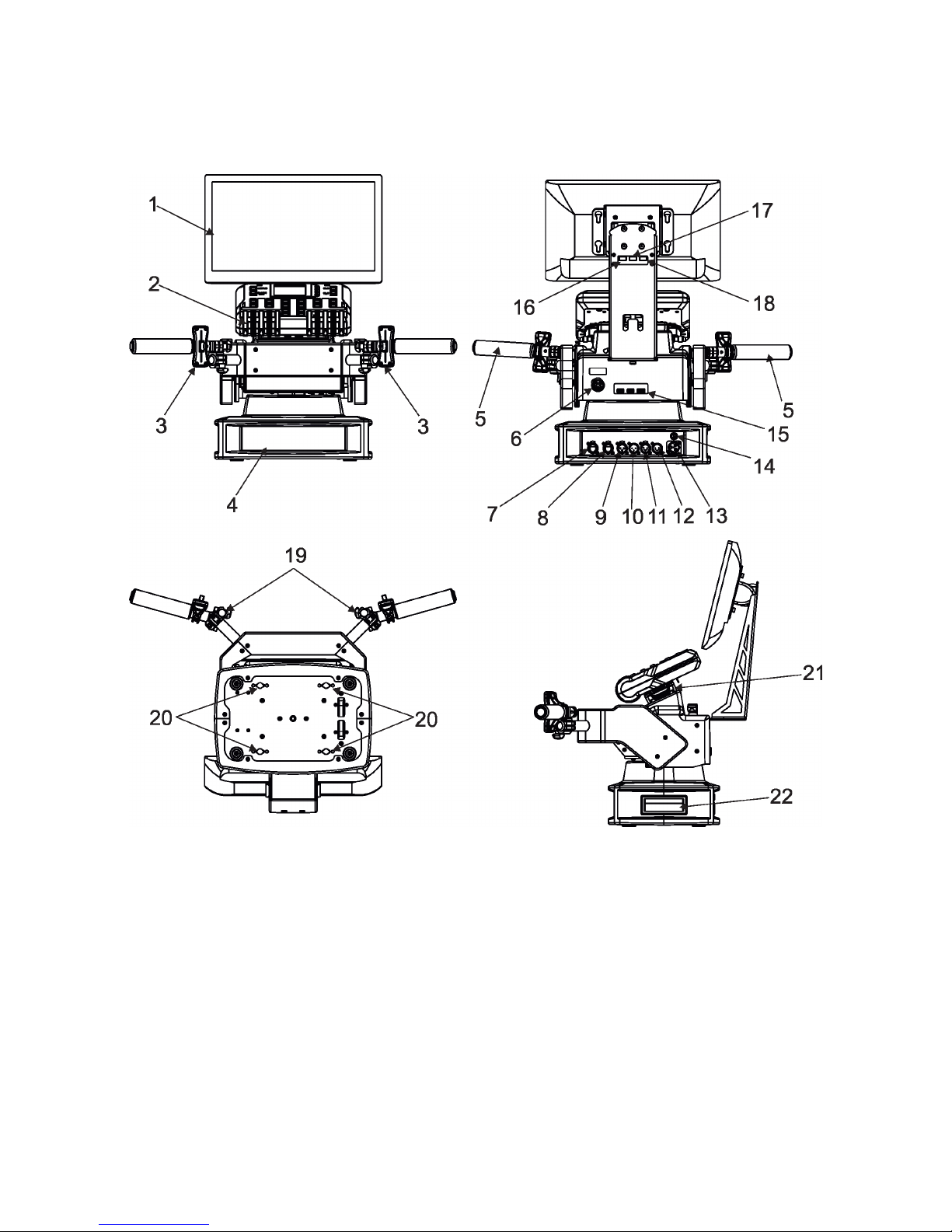
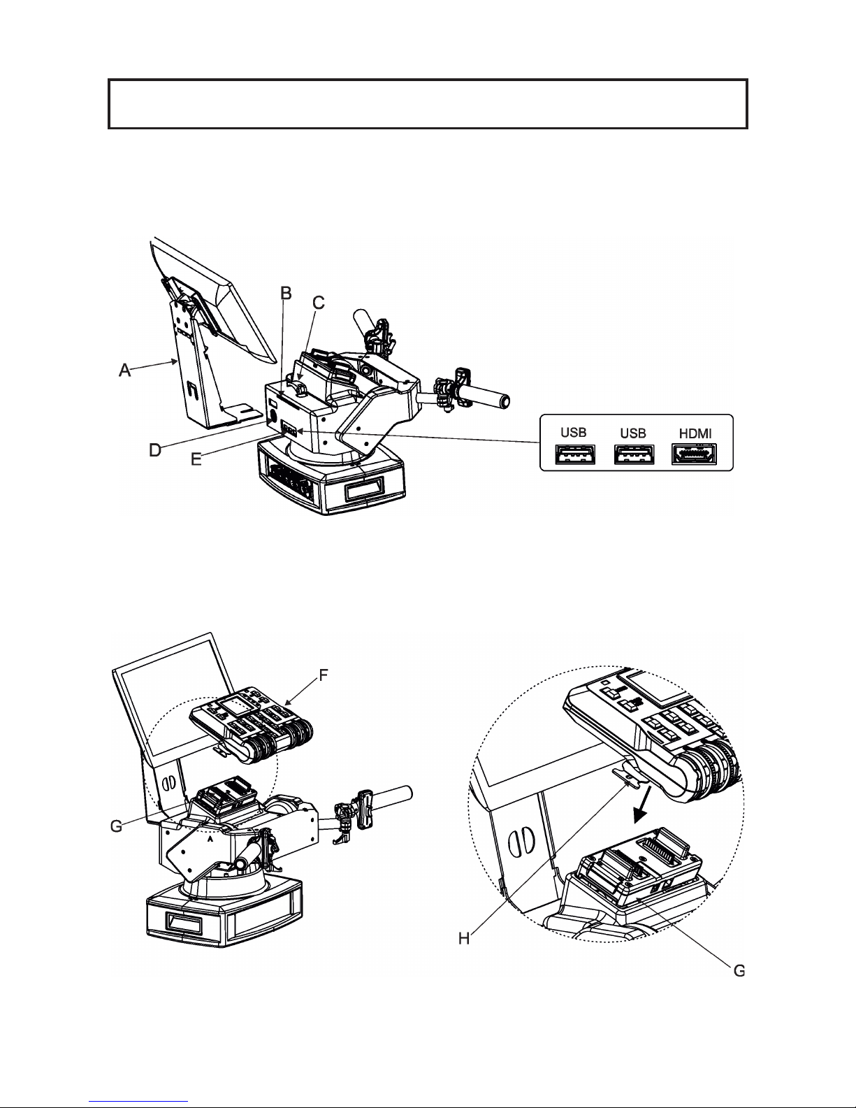
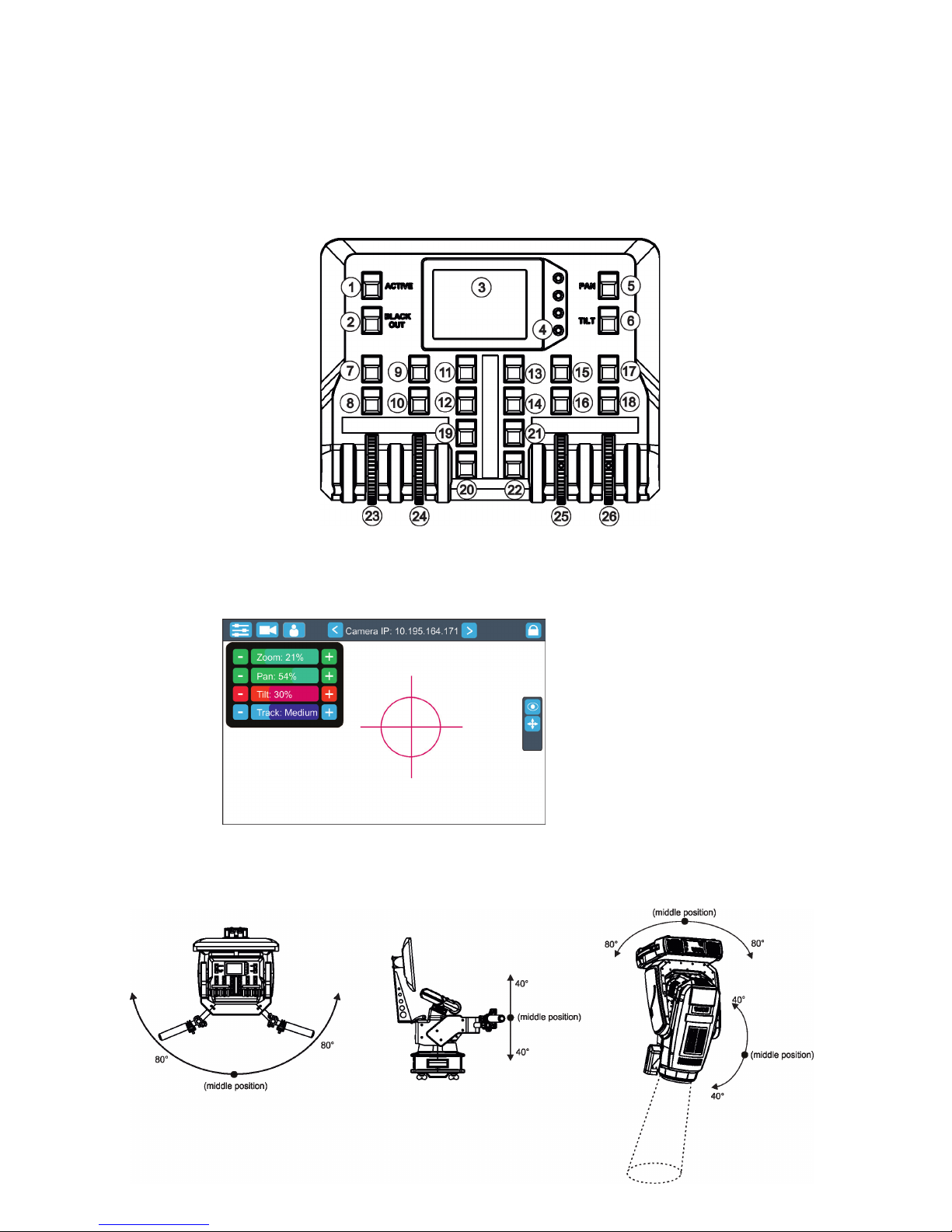
2.1 RoboSpot
1 - Monitor installed on the monitor holder 17 - USB (50mA)
2 - FollowSpot Controller 18 - Input for USB lamp (+5V/50mA)
3 - Faders 19 - Adjusting locks for handles
4 - Base 20 - Apertures for 1/4 turn locks
5 - Control handlebars 21 - Base of the FollowSpot Controller
6 - Monitor supply 22 - Manipulation handles
7 - Camera IN (RJ45)
8 - Ethernet (RJ45)
9- (DMX Out (3-pin XLR)
10 - (DMX In (3-pin XLR)
11- (DMX Out (5-pin XLR)
12 - (DMX In (5-pin XLR)
13 - Power (Neutrik PowerCon)
14 - Fuse holder
15 - HDMI output for monitor + 2 x USB
16 - Input for USB lamp (+5V/50mA)
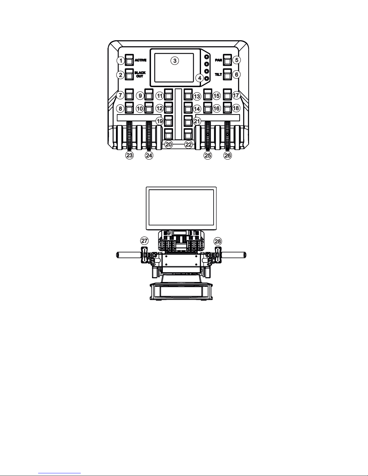
5
1 - Activation button (actives
the FollowSpot Controller)
2 - BlackOut button
3 - Graphic touch screen
4 - Switch On screen button
5 - Pan button(enables/disables
pan motor)
6 - Tilt button(enables/disables
tilt motor)
7 - Preset button
8 - Activation button for jog-wheel
9 - Preset button
10 - Activation button for jog-wheel (24)
11 - Preset button
12 - Preset button
13 - Preset button
14 - Preset button
15 - Preset button
16 - Activation button for jog-wheel (25)
17 - Preset button
18 - Activation button for jog-wheel (26)
19 - Preset button
20 - Preset button
21 - Preset button
22 - Preset button
23 - Jog-wheel
24 - Jog-wheel
25 - Jog-wheel
26 - Jog-wheel
27 - left Fader
28 - Right Fader
2.2 FollowSpot Controller
6
3. Installation
The RoboSpot must be installed by a qualied worker in accordance with
all national and local electrical and construction codes and regulations.
Monitor installation
1. Insert the monitor holder (A) into the slot (B) of the RoboSpot and secure it by means of the lock (C).
The lock must be fully screwed and reclined. Check the monitor is securely fastened.
2. Connect the power cable of LCD monitor to the socket (D), HDMI cable and two USB cables to sockets (E)
in the RoboSpot.
Note: The HDMI connection has to be carried out before connecting the RoboSpot to mains.
FollowSpot Controller installation
1. Place the FollowSpot Controller (F) on the FollowSpot Controller base (G). Connectors on both parts have
to snap each other. Two locks (H) have to be pressed during placing (removing) the FollowSpot Controller (F).
2. If you need to place the RoboSpot on a tripod, you have to install an adaptor with spigot to the tripod.
7
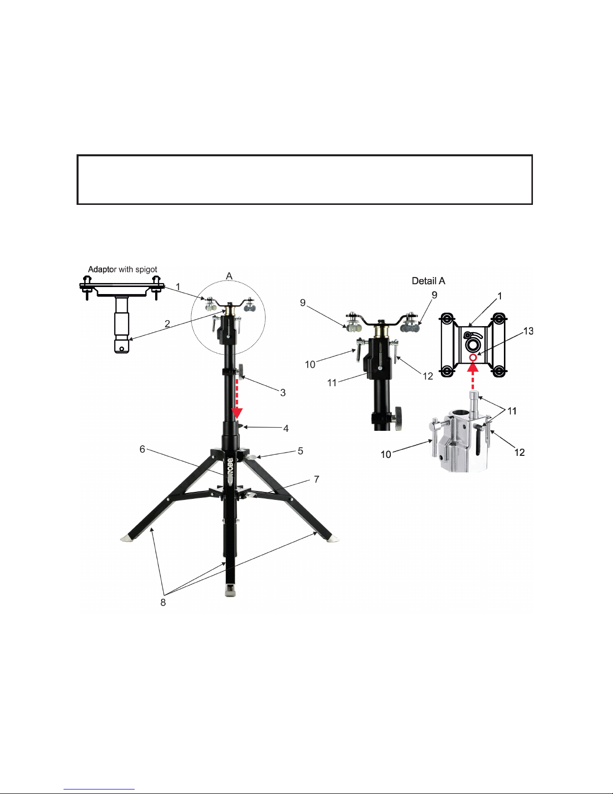
Tripod and adaptor installation
1. Unfold and adjust height of the tripod and distance of legs (8) by means of adjusting locks (4,5,6,7).
The lock (3) has to be in a lower position (as shows arrow on picture below).
2. After inserting the adaptor (1) with spigot (2) to the tripod, the spigot (2) has to be secured by means of
the lock (10) and the adaptor (1) by means of the pin (11) which is inserted to the hole (13) of the adaptor (1)
as shows arrow on picture below. Position of the pin(11) has to be secured by means of the lock (12).
3. The four quarter -turn locks (9) of the adaptor serve for fastening the RoboSpot on the adaptor. Two workers
should install the RoboSpot on the assebled tripod with the adaptor.
Check that all quarter -turn locks (9) are fully tightened before operating the RoboSpot.
Check that all locks (3, 4, 5,6,7, 10,12) are fully tightened before placing
the RoboSpot on the tripod with adaptor.
8
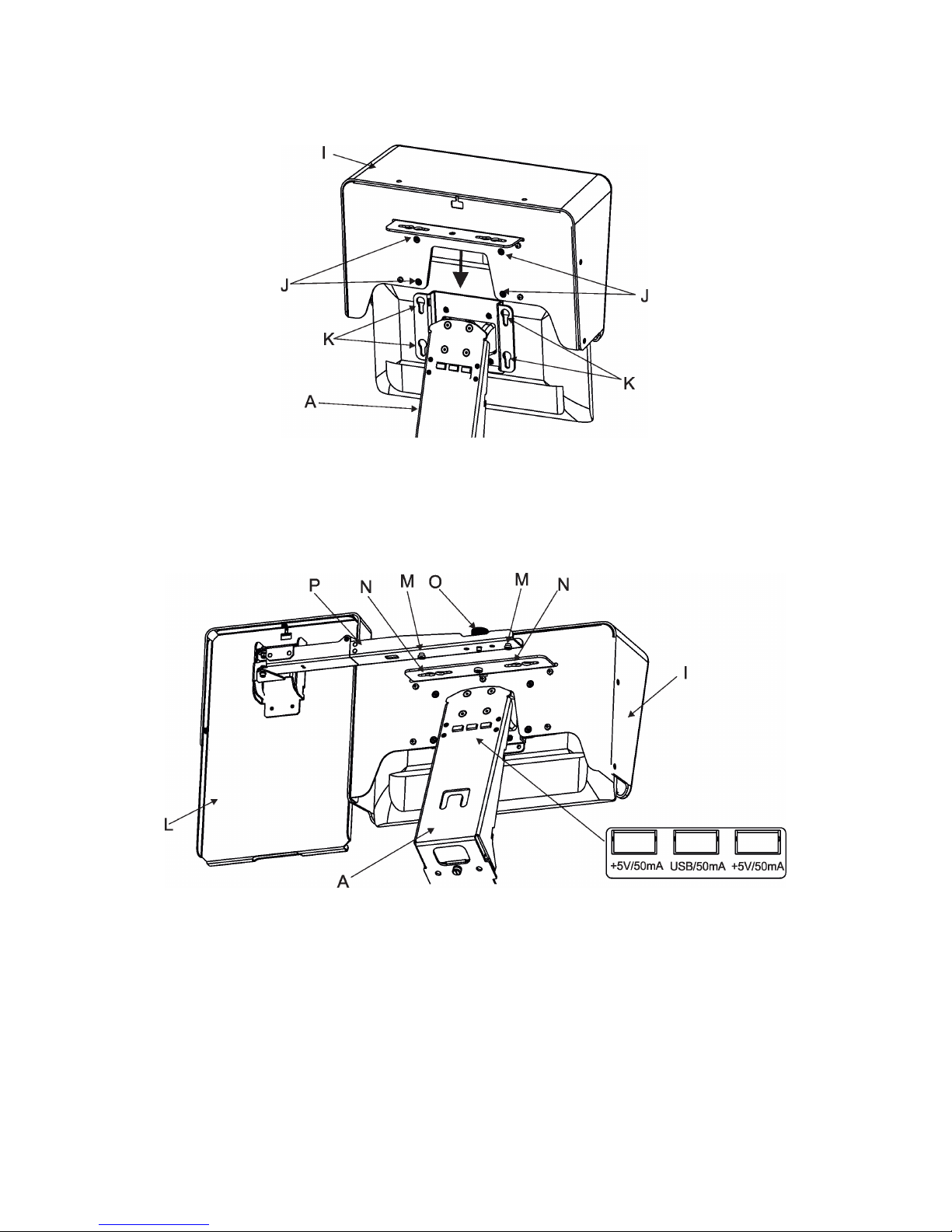
3.1 Monitor shield and note holder installation
1. Place the monitor shield (I) on the monitor holder (A) in this way that pins (J) of the monitor shield snap to
apertures (K) in the monitor holder and move the monitor shield down until you rich a stop.
2. Place the note holder (L) on the monitor shield (I) in this way that pins (M) of the arm (P) snap to the apertures
(N) of the monitor shield (I) and move the arm (P) to the left until you rich a stop.
3. Secure the note holder to the monitor shield by means of the knob (O).
4. Connect two cables of USB lamps to the sockets marked +5V/50mA on the monitor holder.
Note. The arm (P) of the note holder (L) can be turned by 180°, this turned position of the arm allows you to
install the note holder on the opposite site of the monitor shield.
9
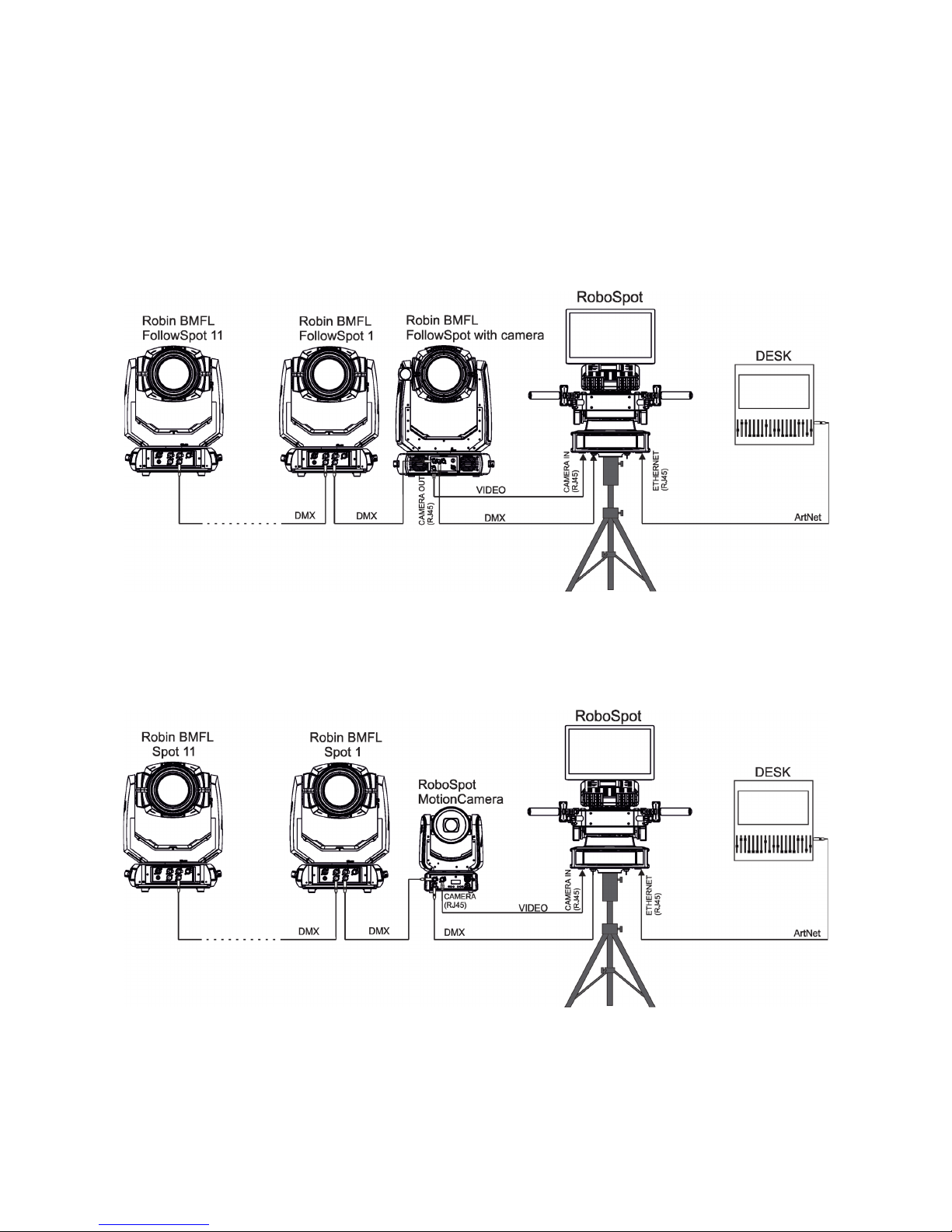
4. RoboSpot connection
After installing the RoboSpot, connect it with the ROBIN BMFL FollowSpot with camera (or the RoboSpot MotionCamera), with another supported ROBIN xtures and a control desk.
You do not need to patch the RoboSpot, but xtures connected to the RoboSpot have to be patched.
Note: Fixtures connected to the RoboSpot and not supported by the RoboSpot will be ignored by the
RoboSpot.
Example 1. Connection with the ROBIN BMFL FollowSpot with camera
Up to 11 ROBIN BMFL FollowSpots can be connected to the ROBIN BMFL FollowSpot with camera.
Example 2. Connection with the RoboSpot MotionCamera
Up to 11 supported ROBIN xtures can be connected to the RoboSpot MotionCamera.The xtures should be
of the same type.
Note. In case of operating the RoboSpot system in interfered environment, Ethernet switches are
recommended in video line (one at the RoboSpot and one at the Robin BMFL FollowSpot or RoboSpot MotionCamera).
10
5. Operation
After installing the RoboSpot and connecting it with the ROBIN BMFL FollowSpot (RoboSpot MotionCamera),
connect the RoboSpot to mains by means of the enclosed power cord.
Press the button ACTIVE (1) in order to activate the FollowSpot Controller. By pressing the button PAN (5) and
TILT (6) you can activate/deactivate of the pan/tilt movement of the ROBIN BMFL FollowSpot (and all connected
BMFL xtures to the RoboSpot).
The button BLACK OUT (2) closes light output of the ROBIN BMFL FollowSpot (and also all connected BMFL
xtures to the RoboSpot).
5.1 Functions mapping
After switching the xture on,touch the Sliders button on the RoboSpot touch screen and use the pan and tilt
sliders to set desired position of the ROBIN BMFL FollowSpot´s head.
It is suitable to set the RoboSpot handlebars to the "middle" position and after that set the pan and tilt position
of the moving head by the sliders on the RoboSpot touch screen.
Sensitivity of pan/tilt movement:
High level (most accurate) - green
slider
Medium level -yellow slider
Low level- red slider
In order to switch sensitivity of pan or
tilt movement to desired level, press
and hold the PAN (5) or TILT (6) button
until the colour of fader is changed.
Sliders button
11
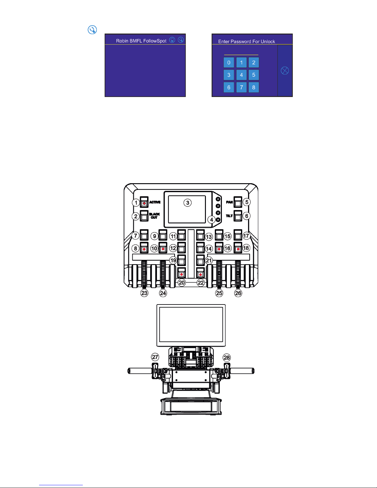
Touch the icon on the FollowSpot Controller to display the password entering screen:
Enter the password (5242) to enter the main menu of the FollowSpot Controller. The password prevents unauthorized person from changing setting of the FollowSpot Controller.
Enter the menu "Functions Mapping". The list of available eects will appear:
If the message" Please Activate FollowSpot Controller!" will appear, press the ACTIVE button (1) on the Follow
Spot Controller.
To assign an eect to the jog-wheels and faders
1.Touch desired eect. Buttons (8/10/16/18) which activate Jog-wheels (23/24/25/26) and buttons (20/22), which
matches faders (27/28) will start to ash.
2.Press desired button and selected eect will be assigned to its jog-wheel (fader).
Assigned eect is displayed in a yellow colour, free eects stay in a white colour.
3.Repeat steps 1 and 2 for needed eects.
12
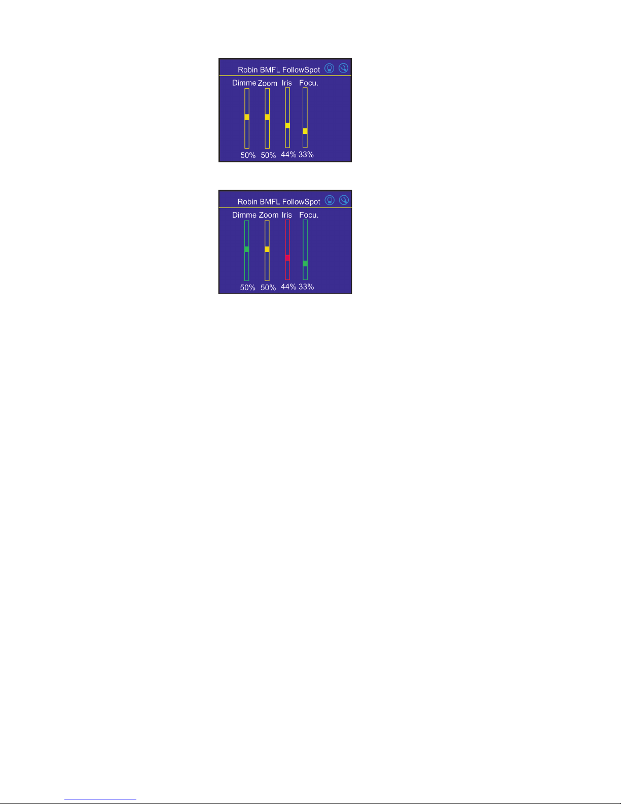
Only eects assigned to the jog-wheels will
appear on this screen.
Eects assigned to the faders will not be
shown.
4.Touch the [cancel] icon and than [back arrow] icon. The screen with eect faders will appear.
E.g.
Sensitivity of the jog-wheels assigned to the eects can be set at three levels: low, medium and high.
The levels of the sensitivity are marked in colour on the screen:
low level - red slider
medium level - yellow slider
high level (most accurate)-
green slider
In order to switch an jog-wheel to desired level of sensitivity, press and hold its activating button (8/10/16/18)
until the colour of fader is changed.
Eects assigned to the four jog-wheels and two faders on the handlebars have a priority over DMX values
coming from a DMX controller.
Functionality of the RoboSpot can by restricted by means of commands on the channel Power/Special Functions
(240-255 DMX) of connected xture.
To control desired eect
1.Use its slider on the screen or press the activating button for its jog-wheel and use this jog-wheel or use a
corresponding fader.
To release an eect from the jog-wheel (fader)
1.Touch desired eect from the list of eects in the menu "Functions Mapping".
2.Touch the option "Unlink".
3.The eect will be displayed in a white colour.
The item "All" allows you to release all assigned eects at one go.
13
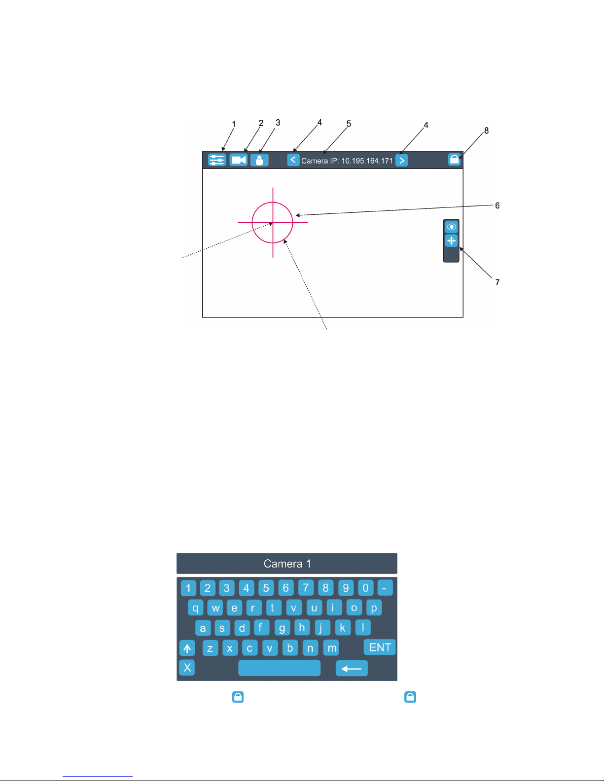
5.2 LCD monitor screen
The RoboSpot is equipped with the 15.6" (10-point) touch screen with max. resolution 1366 x 768.
1. After switching the RoboSpot and the ROBIN BMFL FollowSpot (or the RoboSpot MotionCamera) on, image
scanned by the camera is displayed.
1- Slider button
2- Camera button
3- User button
4 - Camera selection buttons*
5- IP address of selected camera
6 - Position circle (red)
7 - Action toolbar
8 - Screen lock**
*You can change the name of selected camera. To rename selected camera, touch for two seconds the camera
name (e.g. Camera IP: 10.195.164.171).
The software touch keyboard will appear. Use the keyboard to type a new name of camera (e.g. Camera 1).
Touch ENT to save the new name of the camera. The new name is saved into camera (in case that you will
use other Robospot, the new camera name will be reloaded)
Touch the key X to close the keyboard.
** To lock the screen, touch the button . To unlock the screen, touch the button and the the software touch
keyboard will appear. Type a correct password (the password is the same as the password for the FollowSpot
Controller, default password is 5242) and conrm it by touching the key ENT.
Touch the key X to close the keyboard.
.
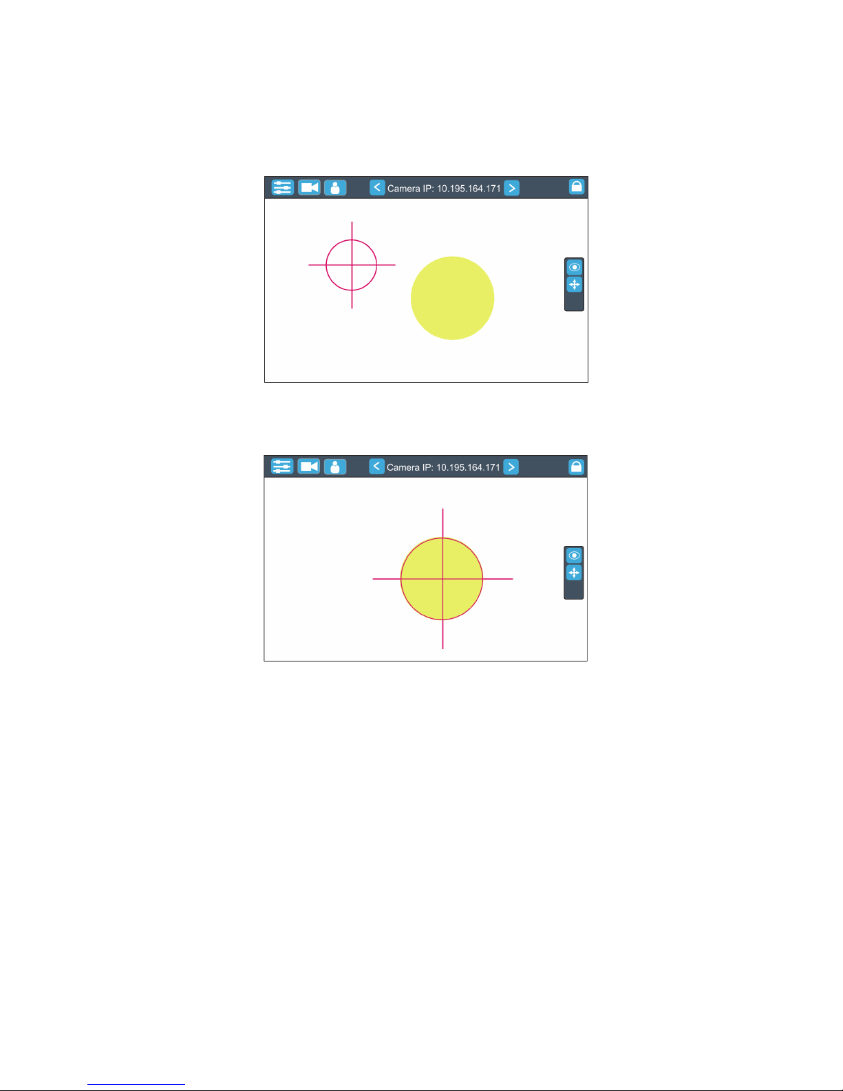
Touch the centre of the
positioning cross and
move the positioning
cross to desired
position on the screen.
Touch the edge of the positioning circle and move it in/out
to decrease/increase the size of the circle
14
Note: the message "Not correct camera settings! Reset camera settings?" informs you that the RoboSpot
software and the camera settings are not accordance.
Use the option "Yes" to set correct camera settings.
The option "Yes" has the same eect as the option "Factory reset " in the Camera button menu.
2. After switching the ROBIN BMFL FollowSpot lamp on and adjusting its beam (zoom, focus, dimmer....), aim
the beam to desired position by means of the FollowSpot Controller handlebars.
3. Move the position circle on the beam image. Now, when you move with the control handlebars, both beam
image and position circle on the screen will move synchronously. It is useful in case that the light output from
the xture is closed and by means of the sighting point you approximately know the position of the light beam.
 Loading...