

Page 1

Version 1.8
1
Page 2

Robin DL7F Wash
Table of contents
1. Safety instructions ......................................................................................................... 3
2. Operating determination ................................................................................................ 4
3. Fixture exterior view ...................................................................................................... 5
4. Installation....................................................................................................................... 6
4.1 Connection to the mains ............................................................................................ 6
4.2 Replacing the frost .................................................................................................... 6
4.3 Replacing the front lens ............................................................................................ 7
4.4 Installing the top hat .................................................................................................. 7
4.5 Rigging the xture ...................................................................................................... 8
4.6 DMX-512 connection ................................................................................................ 10
4.7 Ethernet connection ................................................................................................. 11
4.8 Wireless DMX operation .......................................................................................... 13
5. Remotely controllable functions ................................................................................. 14
6. Control menu map ........................................................................................................ 16
7. Control menu ............................................................................................................... 20
7.1 Tab " Address" .......................................................................................................... 21
7.2 Tab "Information" ...................................................................................................... 22
7.3 Tab "Personality" ......................................................................................................24
7.4 Tab "Manual Control" ................................................................................................ 26
7.5 Tab "Stand-alone" .................................................................................................... 26
7.6 Tab "Service" ............................................................................................................ 27
8. RDM ............................................................................................................................... 30
9. Error and information messages ................................................................................ 31
10. Technical Specications ............................................................................................ 33
11. Maintenance and cleaning ......................................................................................... 36
11.1 Disposing of the product ......................................................................................... 36
12. change log .................................................................................................................. 36
13. Photometric diagrams ............................................................................................... 37
2
Page 3
CAUTION!
Keep this device away from rain and moisture!
Unplug mains lead before opening the housing!
FOR YOUR OWN SAFETY, PLEASE READ THIS USER MANUAL CAREFULLY
BEFORE YOU INITIAL START - UP!
1. Safety instructions
Every person involved with installation and maintenance of this device have to:
- be qualied
- follow the instructions of this manual
CAUTION!
Be careful with your operations.
With a high voltage you can suer
a dangerous electric shock when touching the wires!
This device has left our premises in absolutely perfect condition. In order to maintain this condition and to ensure a safe operation, it is absolutely necessary for the user to follow the safety instructions and warning notes
written in this manual.
Important:
The manufacturer will not accept liability for any resulting damages caused by the non-observance of this
manual or any unauthorized modication to the device.
Please consider that damages caused by manual modications to the device are not subject to warranty.
Never let the power-cord come into contact with other cables! Handle the power cord and all connections with
the mains with particular caution!
Make sure that the available voltage is not higher than stated on the rear panel.
WARNING! This unit does not contain an ON/OFF switch. Always disconnect power input cable
to completely remove power from unit when not in use or before cleaning or servicing the unit.
Make sure that the power cord is never crimped or damaged by sharp edges. Check the device and the pow-
er-cord from time to time.
Always disconnect from the mains, when the device is not in use or before cleaning it. Only handle the power-cord by the plug. Never pull out the plug by tugging the power cord.
This device falls under protection class I. Therefore it is essential to connect the yellow/green conductor to earth.
The electric connection, repairs and servicing must be carried out by a qualied employee.
Do not connect this device to a dimmer pack.
During the initial start-up some smoke or smell may arise. This is a normal process and does not necessarily
mean that the device is defective.
Do not touch the device’s housing bare hands during its operation (housing becomes hot)!
For replacement use fuses of same type and rating only.
Warning! Risk Group 2 LED product according to EN 62471.
LED light emission. Risk of eye injury.
Do not look straight at the xture´s LED source during operation. The intense light
beam may damage your eyes.
3
Page 4
Do not view the light output with optical instruments or any device that may
conncentrate the beam.
The light source contains blue LEDs.
2. Operating determination
This device is a moving head for creating decorative eects and was designed for indoor use only.
This device is for professional use only. It is not for household use.
If the device has been exposed to drastic temperature uctuation (e.g. after transportation), do not switch it on
immediately. The arising condensation water might damage your device. Leave the device switched o until
it has reached room temperature.
Do not shake the device. Avoid brute force when installing or operating the device.
Never lift the xture by holding it at the projector-head, as the mechanics may be damaged. Always hold the
xture at the transport handles.
When choosing the installation-spot, please make sure that the device is not exposed to extreme heat, moisture
or dust. There should not be any cables lying around. You endanger your own and the safety of others!
Make sure that the area below the installation place is blocked when rigging, derigging or servicing the xture.
Always x the xture with an appropriate safety rope. Fix the safety rope at the correct holes only.
Only operate the xture after having checked that the housing is rmly closed and all screws are tightly fastened.
The maximum ambient temperature 45°C must never be exceeded.
CAUTION!
The lens has to be replaced when it is obviously damaged,
so that its function is impaired, e. g. due to cracks or deep scratches!
Operate the device only after having familiarized with its functions. Do not permit operation by persons not
qualied for operating the device. Most damages are the result of unprofessional operation!
Do not block the front objective lens with any object when the xture is under operation.
The xture housing never must be covered with cloth or other materials.
Please use the original packaging if the device is to be transported.
Please consider that unauthorized modications on the device are forbidden due to safety reasons!
If this device will be operated in any way dierent to the one described in this manual, the product may suer
damages and the guarantee becomes void. Furthermore, any other operation may lead to dangers like short-circuit, burns, electric shock, burns etc.
CAUTION!
To avoid damage of the internal parts of the xture head, never let the sunlight lights
directly to the front lens , even when the xture is not working !
4
Page 5
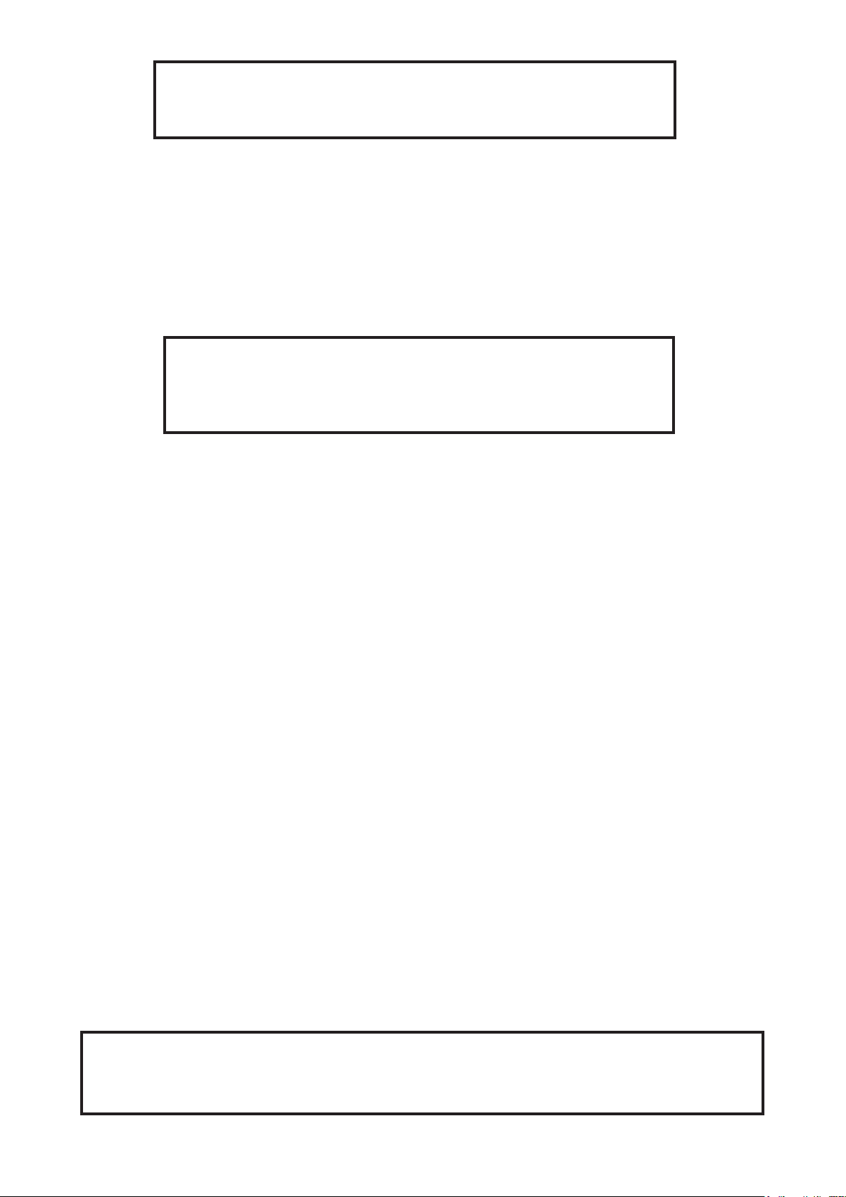
3. Fixture exterior view
1 - Moving head
2 - Fresnel (PC) lens
3 - Pan lock
4 - Base
5 - Handle
6 - Arm
7 -Tilt lock
The head should be locked for transportation- the tilt lock latch (7) and the pan lock latch (3) have to be in the
locked positions. To unlock the head, move these latches to unlock positions before operating the xture.
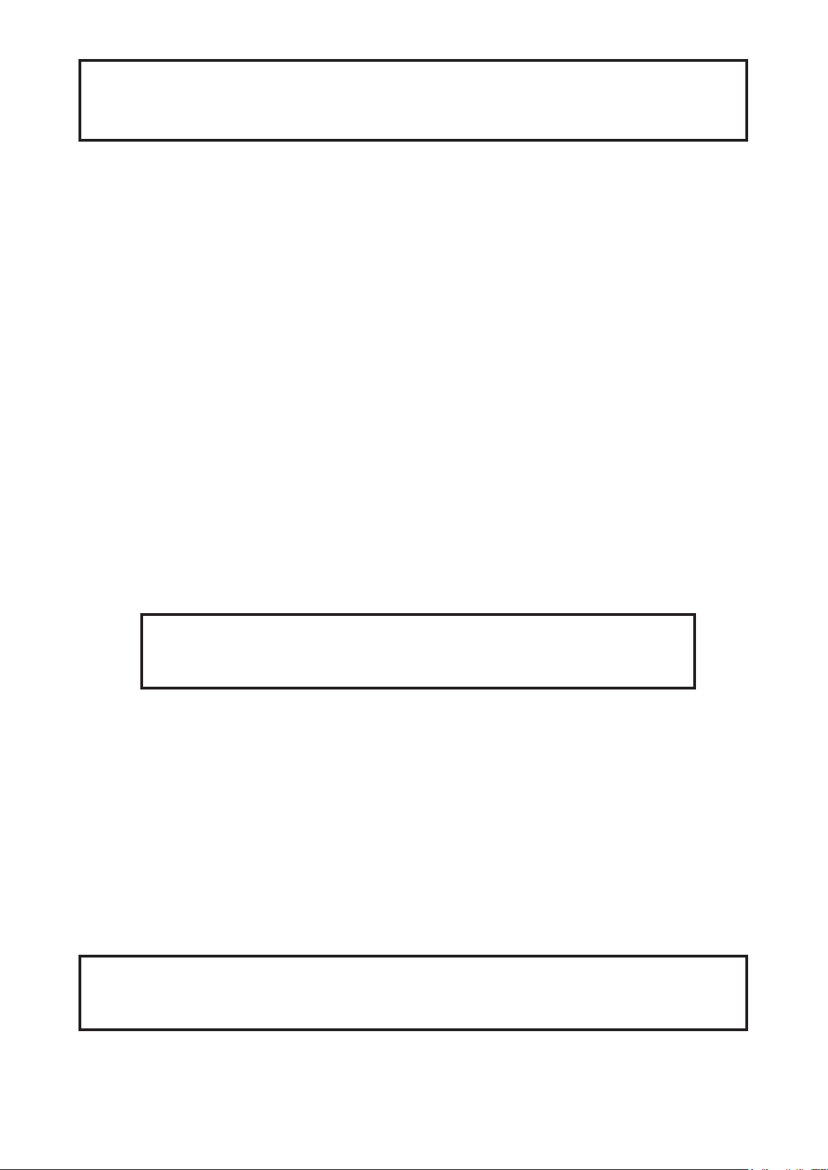
Rear panel of the base:
1 - Ethernet input-RJ45
2 - Fuse holder
3 - 3-pin DMX output
4 - 5-pin DMX output
5 - PowerCon
6 - 3-pin DMX input
7 - 5-pin DMX input
Front panel of the base:
1 - QVGA touch screen
2 - ESCAPE button
3 - NEXT button
4 - ENTER/DISPLAY ON button
5 - PREV button
The ENTER/DISPLAY ON button also serves for switching the display on when the xture is disconnected
from the mains.
5
Page 6
4. Installation
Fixtures must be installed by a Qualied electrician in accordance with all
national and local electrical and construction codes and regulation.
4.1 Connection to the mains
For protection from electric shock, the xture must be earthed!
The Robin DL7F is equipped with auto-switching power supply that automatically adjusts to any 50-60Hz AC
power source from 100-240 Volts.
Power cord is enclosed to the xture. Install a suitable plug on the power cord if needed, note that the cores in
the power cord are coloured according to the following table. The earth has to be connected!
If you have any doubts about proper installation, consult a qualied electrician.
Core (EU) Core (US) Connection Plug Terminal Marking
Brown Black Live L
Light blue White Neutral N
Yellow/Green Green Earth
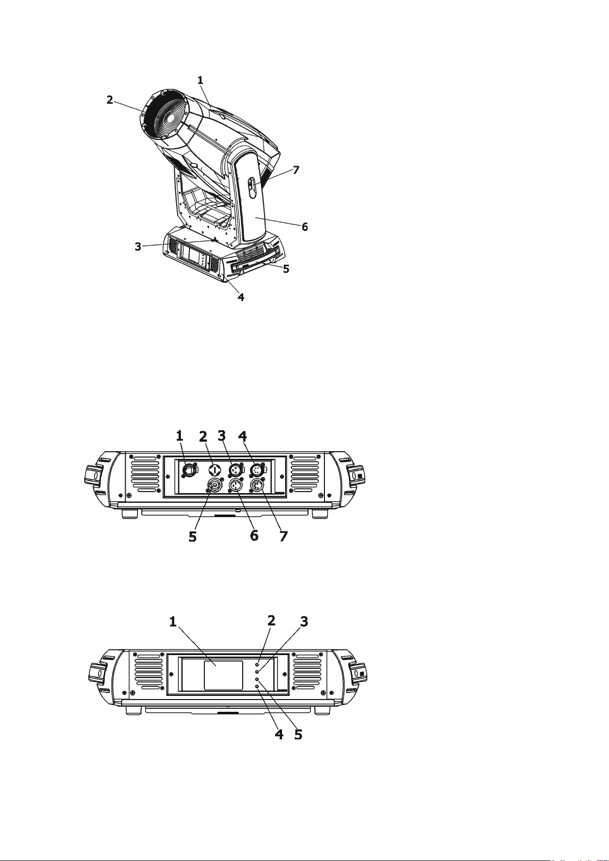
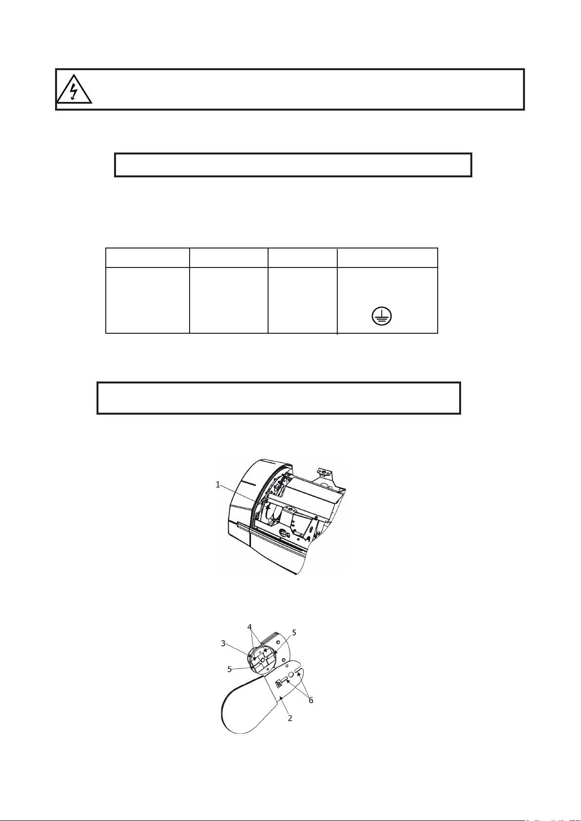
4.2 Replacing the frost
Install frost module with the device switched o only.
Unplug from mains before!
To replace the frost module.
1. Disconnect the xture from mains and allow it to cool for 10 minutes.
2. Remove plastic cover of the head by loosening the 4 quarter-turn fasteners on the cover to get access to
the frost module (1).
3
. The holder (2) of the frost foil is fastened to the frost holder (3) by means of the four magnets (4). Grip the
holder (2) and carefully tilt it out to break a force of magnets (4) on the frost holder (3).
4
. Place a new frost module into the frost holder (3). The glass heat lter has to face towards the light source
(LED module)! Check, that both slots (6) snapped correctly into two protrusions (5) in the holder (3).
5. P
lace the plastic cover back on the xture before applying power.
6
Page 7
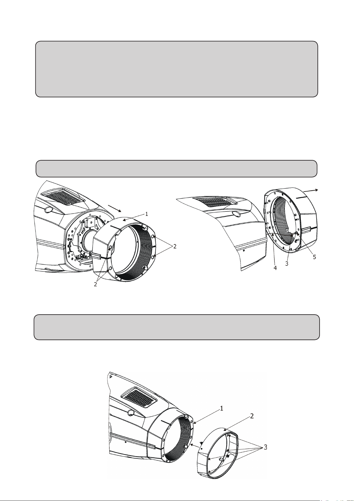
4.3 Replacing the front lens
DANGER!
Unplug the xture from mains before installation.
The front lens is heavy!
Secure the head in a horizontal position by means of the pan/tilt locks before lens re-
placing.
To replace the front lens
1. Disconnect the xture from mains and allow it to cool.
2. Secure xture´s head in a horizontal position.
2. Use a at head screwdriver to unlock 4 quarter-turn fasteners (2) and remove the lens (1) from the head.
Be careful, the lens is heavy.
3. Unscrew the bolt (3) of the secure wire (4) from the nut (5).
4. Screw the bolt of the safety wire of the new lens (4) into the nut (5).
5. Place the new lens on the head (1) and tighten the 4 quarter-turn fasteners (2).
Never operate the xture with unsecured lens to the head.
4.4 Installing the top hat
DANGER!
Unplug the xture from mains before installation.
1. Place the top hat (2) on the front lens holder (1) and tighten the four fastening Allen head bolts (3) using
an Allen key 3.
2. Check, that all screws are fully tighten.
7
Page 8
4.5 Rigging the xture
A structure intended for installation of the xture(s) must safely hold weight of the xture(s) placed on it. The
structure has to be certicated to the purpose.
The xture(s) must be installed in accordance with national and local electrical and construction codes and
regulation.
.
For overhead installation, the xture must be always secured with a safety wire that
can bear at least 10 times the weight of the xture
When rigging, derigging or servicing the xture staying in the area below the installation place, on bridges,
under high working places and other endangered areas is forbidden.
The operator has to make sure that safety-relating and machine-technical installations are approved by an
expert before taking into operation for the rst time and after changes before taking into operation another time.
The operator has to make sure that safety-relating and machine-technical installations are approved by a skilled
person once a year.
Allow the xture to cool for ten minutes before handling.
The projector should be installed outside areas where persons may walk by or be seated.
IMPORTANT! OVERHEAD RIGGING REQUIRES EXTENSIVE EXPERIENCE, including calculating working
load limits, installation material being used, and periodic safety inspection of all installation material and the
projector. If you lack these qualications, do not attempt the installation yourself, but use a help of professional
companies.
CAUTION: Fixtures may cause severe injuries when crashing down! If you have doubts concerning the safety
of a possible installation, do not install the xture!
The xture has to be installed out of the reach of public.
The xture must never be xed swinging freely in the room.
.
Danger of re !
When installing the device, make sure there is no highly inammable
material (decoration articles, etc.) in a distance of min. 0.5 m.
CAUTION!
Use 2 appropriate clamps to rig the xture on the truss.
Follow the instructions mentioned at the bottom of the base.
Make sure that the device is xed properly! Ensure that the
structure (truss) to which you are attaching the xtures is secure.
The xture can be placed directly on the stage oor or rigged in any orientation on a truss without altering its
operation characte ristics .
For securing a xture to the truss, install two safety wires which can hold at least 10 times the weight of the
xture. Use only the safety wires with screw-on carabines.
8
Page 9
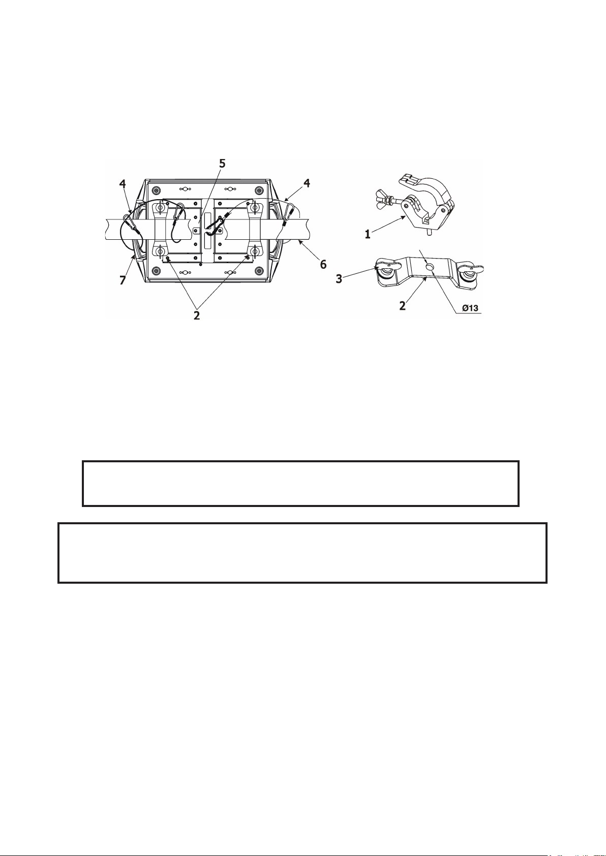
Truss installation
1. Bolt each clamp (1) to the omega holder (2) with M12 bolt and lock nut through the hole in the holder.
2. Fasten the omega holders to the bottom of the base by inserting both quick-lock fasteners (3) into
the holes of the base and tighten fully clockwise.
3. Clamp the xture on a truss (6) and tighten the rigging clamps.
4. Pull one safety wire (4) around the truss (6) and through the handle (7) and another safety wire (4) pull
around the truss (6) and through the handle (7) and lock the screw-on carabine through attachment point (5)
as shown on the picture below.
1-Clamp
2-Omega holder
3-Quick-lock fastener
4-Safety wire
5-Attachment point
6-Truss
7-Handle
When installing xtures side-by-side,
avoid illuminating one xture with another!
DANGER TO LIFE!
Before taking into operation for the rst time,the installation has to be approved by
an expert!
9
Page 10
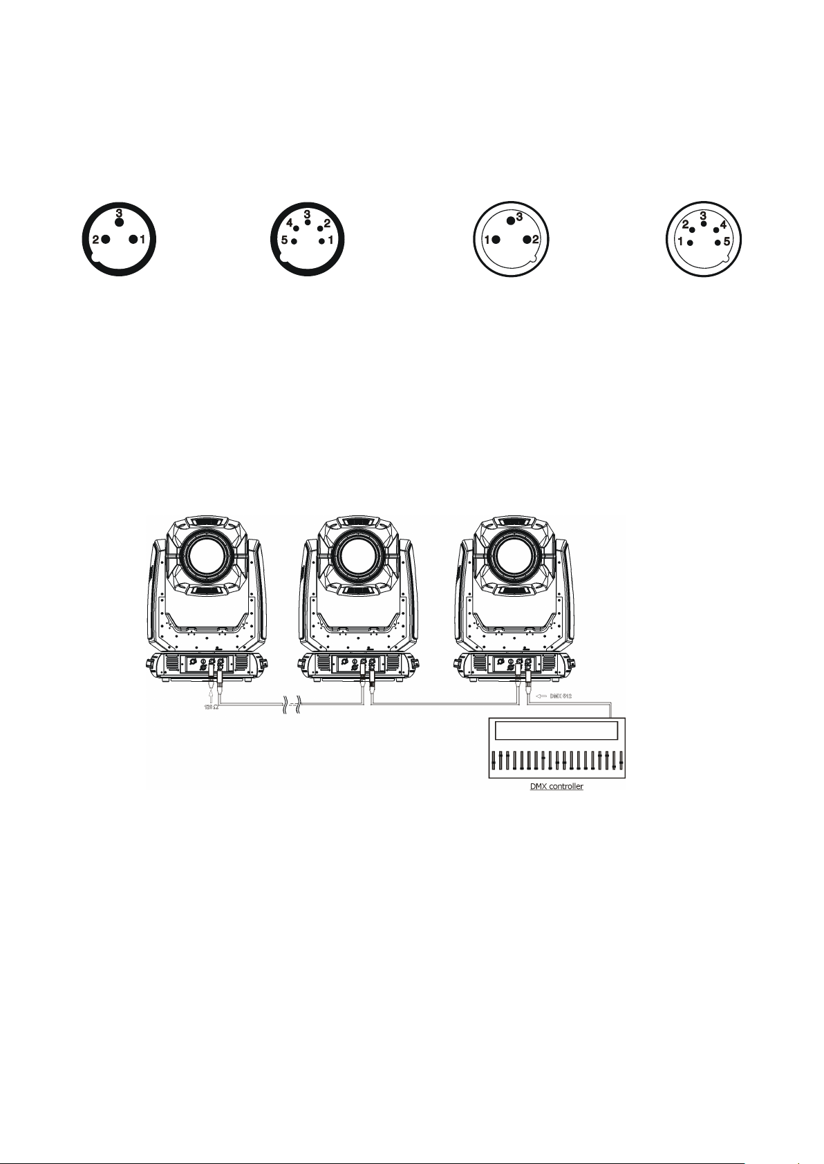
4.6 DMX-512 connection
The xture is equipped with both 3-pin and 5-pin XLR sockets for DMX input and output.The sockets are wired
in parallel.
Only use a shielded twisted-pair cable designed for RS-485 and 3-pin or 5-pin XLR-plugs and connectors in
order to connect the controller with the xture or one xture with another.
DMX - output DMX-input
XLR mounting-sockets (rear view): XLR mounting-plugs (rear view):
1 - Shield
2 - Signal (-)
3 - Signal (+)
4 - Not connected
5 - Not connected
If you are using the standard DMX controllers, you can connect the DMX output of the controller directly with
the DMX input of the rst xture in the DMX chain. If you wish to connect DMX controllers with other XLR-outputs, you need to use adapter-cables.
Building a serial DMX-chain:
Connect the DMX-output of the rst xture in the DMX chain with the DMX-input of the next xture. Always connect
one output with the input of the next xture until all xtures are connected. Up to 32 xtures can be conected.
Caution: At the last xture, the DMX-cable has to be terminated with a terminator. Solder a 120 Ω resistor
between Signal (–) and Signal (+) into a 3-pin XLR-plug and plug it in the DMX-output of the last xture.
1 - Shield
2 - Signal (-)
3 - Signal (+)
4 - Not connected
5 - Not connected
10
Page 11
4.7 Ethernet connection
The xtures on a data link are connected to the Ethernet with ArtNet communication protocol.The control software running on your PC (or light console) has to support Art-Net protocol.
Art-Net communication protocol is a 10 Base T Ethernet protocol based on the TCP/IP.Its purpose is to allow
transfer of large amounts of DMX 512 data over a wide area using standard network technology.
IP address is the Internet protocol address.The IP uniquely identies any node (xture) on a network.
The Universe is a single DMX 512 frame of 512 channels.
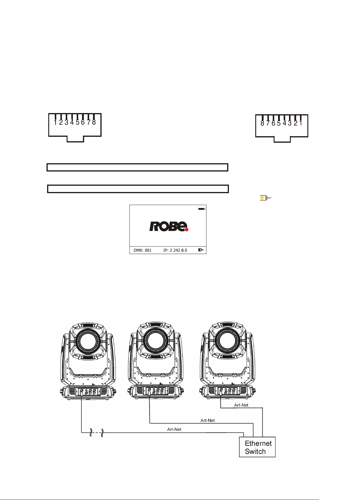
The Robin DL7F is equipped with 8-pin RJ- 45 socket for Ethernet input.Use a network cable category 5 (with
four “twisted” wire pairs) and standard RJ-45 plugs in order to connect the xture to the network.
RJ-45 socket (front view): RJ-45 plug (front view):
1- TD+ 5- Not connected
2- TD- 6- RX-
3- RX+ 7- Not connected
4- Not connected 8- Not connected
Patch cables that connect xtures to the hubs or LAN sockets are wired 1:1,that is,pins with the same numbers
are connected together:
1-1 2-2 3-3 4-4 5-5 6-6 7-7 8-8
If only the xture and the computer are to be interconnected,no hubs or other active components are needed.A
cross-cable has to be used:
1-3 2-6 3-1 4-8 5-7 6-2 7-5 8-4
If the xture is connected with active Ethernet socket (e.g. switch) the network icon will appear at the
bottom right corner of the screen:
Direct Ethernet operation
Connect the Ethernet inputs of all xtures with the Ethernet network.
Option “ Artnet" (gMaI or gMA2 or sACN) has to be selected from “Ethernet Mode” menu at each xture.
Set IP address (002.xxx.xxx.xxx / 010.xxx.xxx.xxx) and the Universe at each xture.
(DMX address=144) (DMX address=48) (DMX address=1)
IP addres=002.168.002.004 IP addres=002.168.002.003 IP addres=002.168.002.002
Universe=1 Universe=1 Universe=1
An advised PC setting: IP address: 002.xxx.xxx.xxx / 010.xxx.xxx.xxx (Dierent from xture IP addresses)
NET mask: 255.0.0.0
11
Page 12
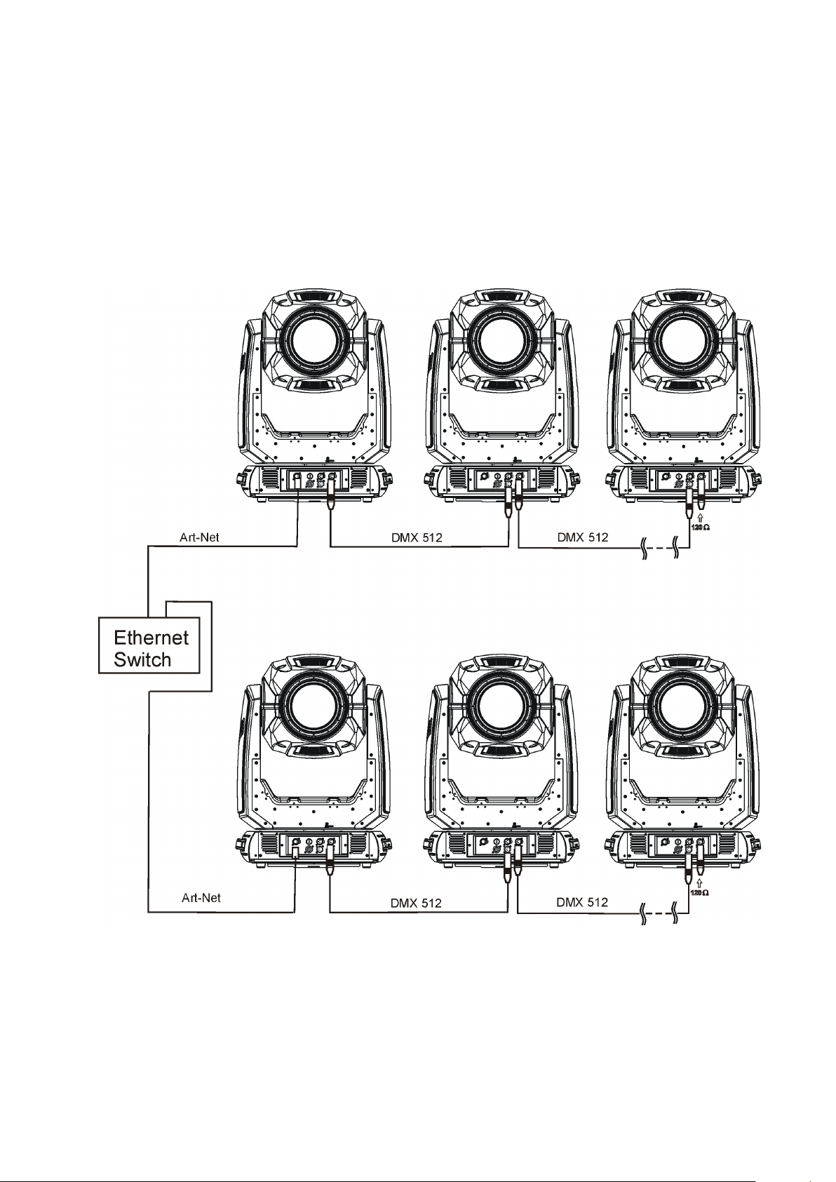
Ethernet / DMX operation
Option “ Artnet" (gMaI or gMA2 or sACN) has to be selected from “Ethernet Mode” menu at rst xture.
Option “Ethernet To DMX” has to be selected from the “Ethernet Mode” menu at the rst xture (connected to
the Ethernet) in the xture chain, next xtures have standard DMX setting.
Connect the Ethernet input of the rst xture in the data chain with the network. Connect the DMX output of this
xture with the input of the next xture until all xtures are connected to the DMX chain.
Caution: At the last xture, the DMX chain has to be terminated with a terminator. Solder a 120 Ω resistor
between Signal (–) and Signal (+) into a XLR-plug and connect it in the DMX-output of the last xture.
Example:
DMX address=1 DMX address=48 DMX address=144
IP addres=002.168.002.002
Universe=0
DMX address=1 DMX address=48 DMX address=144
IP addres=002.168.002.003
Universe=1
12
Page 13
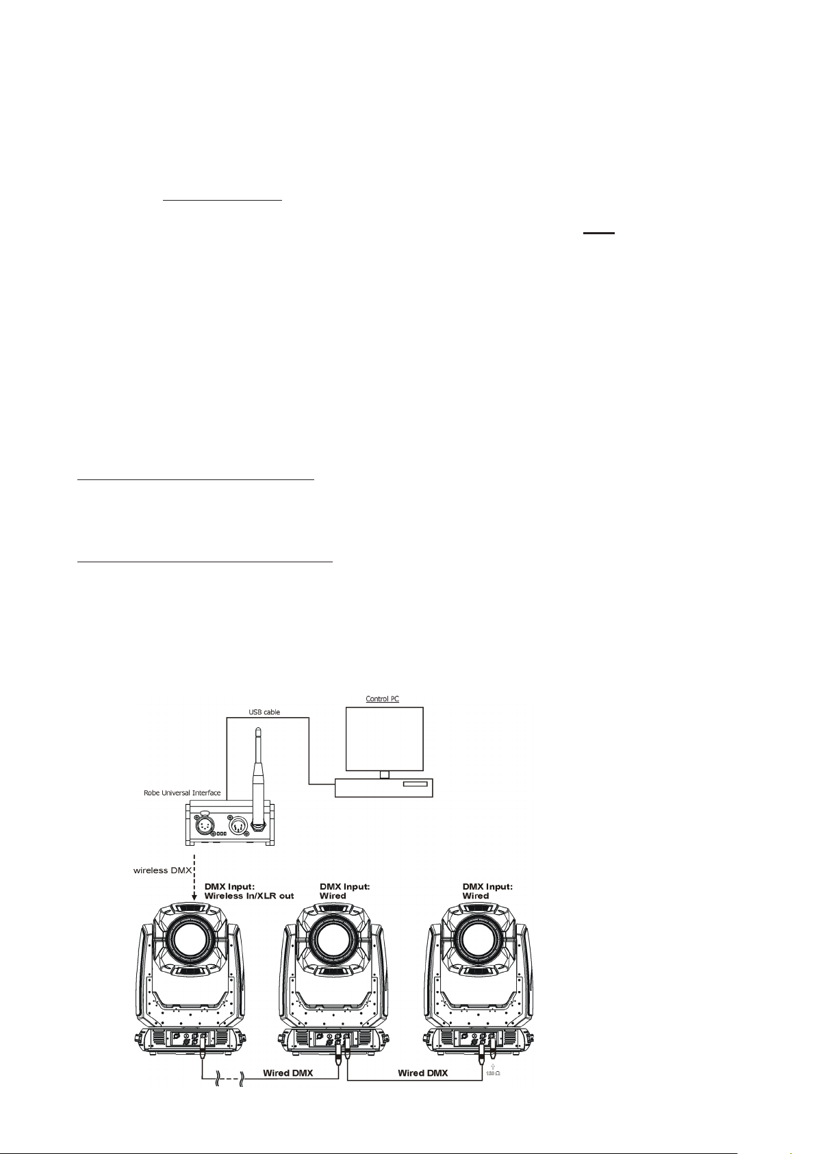
4.8 Wireless DMX operation
The wireless version of the Robin DL7F Wash is equipped with the Lumen Radio CRMX module and antenna
for receiving DMX signal. CRMX module operates on the 2.4 GHz band.
The item " Wireless " from the menu "DMX Input" allows you to activate receiving of wireless DMX (Personality--> DMX Input -->Wireless.). First two options from the "DMX Input" menu are stated in DMX chart as well
(channel Power/Special functions , range of 10-19 DMX). If DMX input option is changed by DMX command,
the change is permanently written into xture´s memory.
DMX range of 10-19 switching xture to the wired/wireless operation is active only during rst 10 seconds after switching the xture on.
After switching the xture on, the xture checks both modes of receiving DMX in the following order:
1. For the rst ve seconds, the xture receives DMX signal from the wired input. If the Power/Special functions
channel is set at some DMX input option, the xture will receive DMX value according to this option. If DMX input
option is set to the wired input , this option is saved and checking procedure is nished. If DMX input option is
not set, the xture continues next 5 seconds in scanning wireless DMX signal-see point 2.
2. For the next 5 seconds the xture receives wireless DMX signal and again detects if the Power/Special
functions channel is set at some DMX input option, if not, the xture will take option which is set in the xture
menu "DMX Input".
To link the xture with DMX transmitter.
The xture can be only linked with the transmitter by running the link procedure at DMX transmitter .
After linking , the level of DMX signal ( 0-100 %) is displayed in the menu item “Wireless State“ (Information
-->Wireless State).
To unlink the xture from DMX transmitter.
The xture can be unlinked from receiver via the menu item “ Unlink Wireless Adapter“ (Information--> Wireless
State --> Unlink Wireless Adapter).
Example:
13
Page 14
5. Remotely controllable functions
Colour mixing system
The colour mixing system allows switching among CMY, RGB and 7 colour system ( red, green, blue, amber,
cyan, light green, Congo blue).
Virtual colour wheel
This wheel contains 80 preset colours and 10 user-denable colours.
To save user colours:
1.Set White Point O (Channel Colour Mix Control, range 70-79 DMX).
2.Mix desired colour on colour channels .
3.Stay in desired position of user colours (216-235 DMX) on the Virtual colour wheel for 1 sec.
4.Leave the range of user colours (216-235 DMX) on the Virtual colour wheel.
5. Repeat steps 2-4 for next user colour
6.To permanently save user colours, stay for 3 sec. at DMX range of 110-114 on the channel Colour functions.
After that the colour system will be reset (this action lasts about 2 minutes). Previous user colours will be
overwritten.
Colour temperarature correction (CTC)
This channel allows to set calibrated white colour from range of 8000K-2700K. The light ouput can be set to
max. intensity or to max. CRI.
Green correction
This channel allows slightly correct tint of white colours.
Frost
Frost module provides variable frost for ne frosting. This frost can be replaced with another frost lter. One
frost lter (20°) is installed in the xture, the second frost lter (10°) is included as optional.
Zoom
Motorized zoom unit enables zoom between 7 °- 32° with fresnel lens and 5°-46° with PC lens ( both ranges
mesured at 1/2 beam).
Dimmer/Shutter unit
Smooth 0 - 100 % dimming is provided by the electronic control unit. This unit is also used for strobe eects
with variable speed.
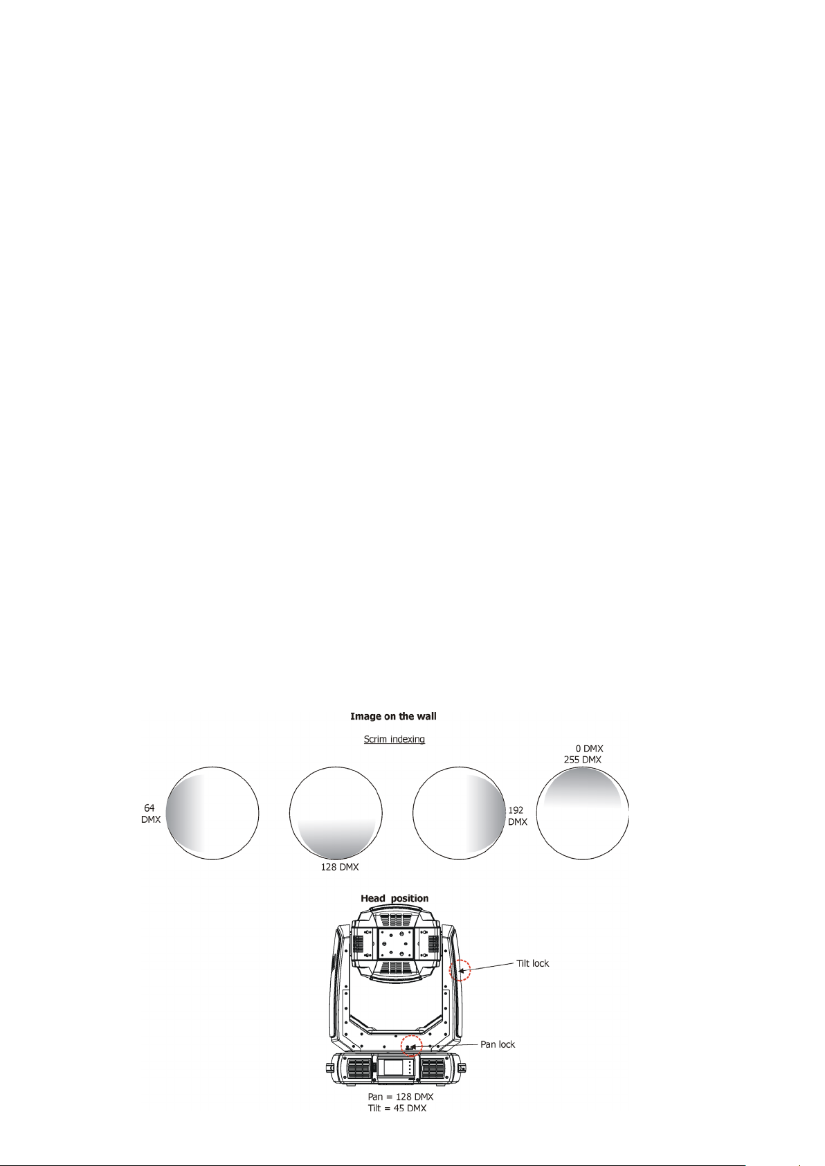
Scrim eect
Indexable scrim eect by 360°. Fine inserting into light beam.
14
Page 15
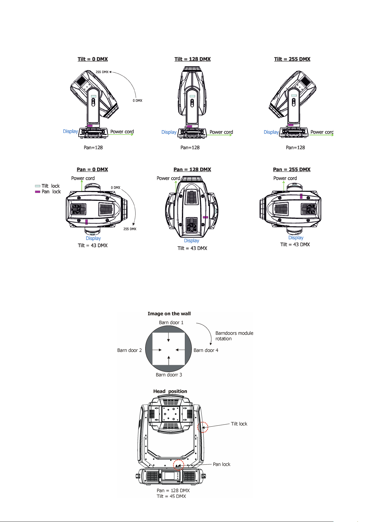
Pan/Tilt
Fast pan/tilt movement due to built-in electronic motion stabilizer (EMS). The electronic motion stabilizer ensures
precise position of the xture´s head during its movement and reduces its swinging when the truss shakes.
Pan /Tilt movement range: 0-540°/0-240°.
Barndoors
The xture uses an internal barndoors module for creating dierent shapes, which also simulates barn door
eects. The module consists of four individually controllable blades and is rotatable by 180 degrees.
Barndoors macros
Pre-dened barndoors macros allow choice from 41 macro eects. Speed of each barndoors eect can be
controlled by the Barndoors macro speed channel.
15
Page 16
6. Control menu map
Default settings=Bold print
Tab Level 1 Level 2 Level 3 Level 4 Level 5 Level 6
Addressing Settings DMX Address 001-512
DMX Presets Mode 1
Mode 2
Mode 3
Mode 4
View Selected Preset
Ethernet Settings Ethernet Mode Disable
ArtNet
gMAI
gMA2
sACN
Ethernet To DMX O, On
IP Address/Net Mask Default IP Address
Custom IP Address
Net Mask
ArtNet Universe 0-255
MANet settings MANetI/II Universe 01-256
MANet Session ID 01-32
sACN Settings sACN Universe 00001-32000
sACN Priority 0-255
Information Fixture Times Power On Time Total Hours
Resetable Hours
Fixture Temperatures
DMX Values Pan
Wireless State
LEDs On Time Total Hours
Resetable Hours
Air Filters Elapsed Time
Alert Period 10-300
LEDs Temperatures Current
Maximum NonRes.
Maximum Res.
LEDs Board Temperature
Ambient Temperature
Base Temperature Current
:
Dimmer Fine
Signal Quality
Current
Maximum NonRes.
Maximum Res.
Current
Maximum NonRes.
Maximum Res.
Maximum NonRes.
Maximum Res.
Unlink Wireless
Adapter
Power Channel state
Colour functions state
Software Versions Display System
Module M
Module L-A
Module L-B
16
Page 17
Tab Level 1 Level 2 Level 3 Level 4 Level 5 Level 6
Module L-C
Module O
Module SC
Module BD
Product IDs Mac Address
RDM UID
RDM Label
View Logs Fixture Errors Pan Errors
:
Temp.Sensor Errors
Fixture States Power On
Power O
Fixture Position
Fixture Temperatures LED Temperatures
Ambient Temperatures
Base Temperatures
Personality User Mode User A Settings
User B Settings
DMX Presets Mode 1
Mode 2
Mode 3
Mode 4
View Selected Preset
DMX Input Wired
Wireless
Wireless In/XLR Out
Pan/Tilt Settings Pan Reverse O, On
Tilt Reverse O, On
Pan/Tilt Feedback O, On
Pan/Tilt mode Time
Speed
Pan/Tilt EMS On, O
Microphone Sensitivity
Blackout Settings Blackout During M.C. O, On
Theatre Mode O
Colour Calibration
Mode
Colour Mixing Mode
UV Stability O, On
Wavelenth Correction
Chromatic White O, On
Output Mode Intensity
Thungsten E. Sim. O
1-10-20
Blackout while: Pan/Tilt moving O, On
Gobo Wheel Moving O, On
Quiet 0-100%
O, On
RGB
CMY
O, On
CRI CRI Settings
750W
1000W
1200W
2000W
Output Uniformity On, O
Output Consistency 30°...50°...65°
CRI Selection 70, 75,80,85,90
17
Page 18
Tab Level 1 Level 2 Level 3 Level 4 Level 5 Level 6
25000W
Init Eect Positions Pan 0-255
:
Dimmer Fine 0-255
Screen Settings Display Intensity 1-10
Screen Saver Delay O-10min.
Touchscreen Lock O-10min.
Recalibrate Touchscreen
Display Orientation Normal
Inverted
Auto
Temperature Unit °C,°F
Fan Mode Auto
High
Dimmer Curve Linear
Square law
Date & Time Settings
Extra Color Functions
Default Settings
Password Protection
Manual Control Reset Functions Total
Manual Eect Con-
trol
O, On
On, O
Pan/Tilt reset
Optics Reset
Beam Shaper Res.
Pan 0-255
:
Dimmer Fine 0-255
Stand -Alone Test Sequences Dynamic Mode
Static Mode Pan 0-255
MusicTrigger O, On
Preset Playback None
Test
Prog. 1
Prog. 2
Prog. 3
Play Program Play Program 1
Play Program 2
Play Program 3
Edit Program Edit Program 1 Start Step 1-80
Edit Program 2 End Step 1-80
Edit Program 3 Edit Program Steps Step 1 Pan 0-255
Tilt 0-255
Zoom 0-255
Focus 0-255
: :
: Dimmer Fine 0-255
: Step Time 0-25,5 sec.
Step 100 Pan 0-255
:
Dimmer Fine 0-255
Step Time 0-25,5 sec.
18
Page 19

Tab Level 1 Level 2 Level 3 Level 4 Level 5 Level 6
Service Adjust DMX Values Pan 0-255
:
Calibrations Calibrate Eects Pan 0-255
LEDS HW Version O , I
Update Software
Dimmer Fine 0-255
:
Bd. Shutter 4 Move 0-255
Calibrate colours Red Calibration
Green Calibration
Blue Calibration
Amber Calibration
Cyan Calibration
Congo Blue Calibration
Light Green Calibration
Green Corrections 2700 K (CRI´70)
3200 K (CRI=70)
4200 K (CRI=70)
5600 K (CRI=70)
8000 K (CRI=70)
2700 K (CRI=90)
3200 K (CRI=90)
4200 K (CRI=90)
5600 K (CRI=90)
8000 K (CRI=90)
Opto Corrections Red correction
Calibrate Pan/Tilt EMS
Load Default Calib-
rations
19
Page 20

7. Control menu
The Robin DL7F Light is equipped with the QVGA Robe touch screen with battery backup which
allows to set the xture´s behaviour according to your needs, obtain information on its operation, test its
various parts and lastly program it, if it has to be used in a stand-alone mode.
The xture´s menu can be controlled either by the control buttons or directly by touching the icon.
Control buttons on the front panel:
[ESCAPE] button used to leave the menu without saving changes.
[NEXT] , [PREV] buttons for moving between menu items and symbols, adjusting values.
[ENTER/Display On] button used to enter the selected menu (menu item) and to conrm adjusted value.
If the xture is disconnected from mains, the button switches the touch screen on.
Icons used in the touch screen menu:
- [back arrow] used to move back to the previous screen (menu).
- [up arrow] used to move up on the previous page.
- [down arrow] used to move down on the next page.
- [conrm] used to save adjusted values, to leave menu or to perform desired action.
- [cancel] used to leave menu item without saving changes.
- [conrm+copy] used to save adjusted values and copy them to the next prog. step.
- [warning icon] used to indicate some error which has occurred in the xture.
- [Ethernet] used to indicate Ethernet connected.
- [menu rotation] used to rotate menu 180 degrees from current orientation.
- [slider control] used to recall slider system for setting desired value.
- [keyboard control] used to recall keyboard system for setting desired value.
- [air lters cleaning] used to signal that cleaning period of the air lters elapsed.
The menu page displays icons for each function that you can perform from the touch screen.
After switching the xture on, the touch screen shows the screen with the ROBE logo:
20
Page 21

Touch any part of the screen or press the [ENTER/Display On] button to display the initial screen with the current stored DMX address:
Note: The green icon at the top right corner of the screen indicates the level of the display battery charging. If
the whole icon is green, the battery is fully charged while the red icon indicates exhausted battery. The battery
charges during xture operation, its charging lasts cca 6 hours.
We recommend that the xture should be in operation at least 7 hours per week to keep the battery fully charged.
If you switch the xture on and this screen will not appear till 1 minute, switch the xture o and on again. If the
screen lights, the battery is exhausted. In case the screen still does not light, the battery is faulty.
This is also indicated by an error message "Faulty battery" and if such an error message appears the battery
should be replaced immediately. The lifetime of the battery is highly dependent on ambient temperature (and
consequently on base temperature). If the maximum ambient temperatures (as recorded and displayed in menu:
Information -> Fixture Temperatures -> Ambient Temperature -> Maximum NonRes.) are kept within the specied limits, the battery should last for at least two years. Shell the ambient temperatures exceed the specied
maximum temperature, the lifetime of the batteries could be considerably shortened even up to just one year
or less and also result in physical damage (battery leakage) or unreliable xture functions.
Damage caused by batteries failed due to exceeded maximum ambient temperature cannot be claimed under
warranty terms.
Touch the green arrow at the bottom right corner of the screen or press the [ENTER/Display On] button to enter
the " Address" menu.
Each item (such as a Tab, menu item, text box, icon) may be selected from a screen by simply touching the
item in the list or by pressing the [NEXT] or [PREV] buttons to scroll through list items. With each press, the
next item is highlighted. Press [ENTER/Display On] to select the highlighted item.
Before rst xture operation, set current date and time in the menu "Date &Time
Setings" (menu path: Personality--> Date &Time Setings).
7.1 Tab " Address"
DMX Address - Select the menu to set the DMX start address.
DMX Preset - Use the menu to select desired channel mode.
DMX Preset - Use the menu to select desired channel mode.
Mode 1 - 34 control channels
Mode 2 - 29 control channels
Mode 3 - 42 control channels
Mode 4 - 33 control channels
View Selected Preset - Use the menu to display channels included in the selected mode.
Ethernet Settings - The menu allows all needed settings for the Ethernet operation
Ethernet Mode
Disable - The option disables Ethernet operation.
Artnet - Fixture
gMAI
gMA2
- Fixture
- Fixture
receives Artnet protocol
receives MANet I protocol
receives MANet 2 protocol
21
Page 22

sACN
- Fixture
receives sACN protocol
Ethernet To DMX - Fixture receives
data to its DMX output (xture works as an "Ethernet/DMX converter",
to its DMX output and you can build a standard DMX chain by connecting another xtures.
Only one xture has to be connected to the Ethernet.
IP Address/Net Mask - Select this menu to set IP address. IP address is the Internet protocol
address.The IP uniquely identies any node (xture) on a network.
There cannot be 2 xtures with the same IP address on the network!
Default IP Address -Preset IP address, you can set up only rst byte of IP address
(2 or 10) e.g. 002.019.052.086.
Custom IP Address - The option enables to set up all bytes of IP address.
Net Mask - The option enables to set up all bytes of Net Mask.
ArtNet Universe - Use
512 frame
MANet Settings - Use this menu to set parameters for MANet operation.
MANet Universe I/II - The value of this item can be set in range 1-256.
MANet Session ID - The value of this item can be set in range 1-32.
sACN Settings - Use this menu to set parameters for sACN operation.
sACN Universe - The value of this item can be set in range 1-32000.
sACN Priority - The value of this item can be set in range 0-255.
this item to set a Universe (0-255). The Universe is a single DMX
protocol
of 512 channels.
from the Ethernet input and sends DMX
next xture can be connected
7.2 Tab "Information"
Fixture Times - The menu provides readouts of xture and LED module operation hours.
Power On Time Hours - Select this menu to read the number of xture operation hours.
Total Hours -
Robin DL7F
Resetable Hours -
Robin DL7F
In order to reset this counter to 0, touch the text box next to the item "Resetable Hours:"
LEDs On Time - Select this menu to read the number of LEDs operation hours.
In order to reset some counter to 0, touch the yellow text box next to desired colour.
Air Filters - Regular cleaning of the air lters is very important for the xture´s life and performance.
Bild-up of dust, dirt and fog uid residues reduces the xture´s light output and cooling ability.
The two items of this menu help you to keep cleaning period of the air lters.
Alert period - Cleaning schedule for the xture depends on the operating environment.
It is therefore impossible to specify accurate cleaning interval. This item allows
you to change the cleaning interval of the air lters. This "alert" value is 300 hours and it
is set as default. Inspect the xture within its 300 hours of operation to see whether cleaning
is necessary. If cleaning is required, clean all air lters and change the value in this menu
on acceptable level. Min. level of alert period is 10 hours, max. is 300 hours.
Elapsed Time - The item allows you to read the time which remains to cleaning air lters.
The time period is set in the menu mentioned above.
Expired time period is signalled by a negative mark (-) at the time value and a warning icon
on the display.
Clean the lters and reset this menu item (by touching the text box next to the item
"Elapsed Time").
Fixture Temperatures - The menu is used to view temperatures of the xture´s inside.
LEDs temperatures - The menu shows temperature on the LED PCBs in the light source (RA-red + amber
LEDs, GCY-green + cyan+light green LEDs, BU-blue+congo blue LEDs).
Cur. - A current temperature of the LED PCBs.
The item shows the total number of the operation hours since the
has been fabricated.
The item shows the number of the operation hours that the
has been powered on since the counter was last reset.
22
Page 23

Max. - A maximum temperature of the LED PCBs since the xture has
been fabricated.
Max. Res. - A maximum temperature of the LED PCBs since the counter
was last reset.
In order to reset some counter to 0, touch desired text box under item "Max.Res."
LEDs Board Temperature - The menu shows temperature in the xture head on the LEDs control PCB.
Current - A current temperature on the LEDs control PCB.
Maximum NonRes. - A maximum temperature on the LEDs control PCB since
the xture has been fabricated.
Maximum Res. - A maximum temperature on the LEDs control PCB since the counter
was last reset.
In order to reset this counter to 0, touch the text box next to the item "Maximum Res."
Ambient Temperature - The menu shows temperature next to AC-DC power supplyies in the xture base .
Current - A current temperature next to AC-DC power supplyies in the xture base.
Maximum NonRes. - A maximum temperature next to AC-DC power supplyies in
the xture base since the xture has been fabricated.
Maximum Res. - A maximum temperature next to AC-DC power supplyies in
the xture base since since the counter was last reset.
In order to reset this counter to 0, touch the text box next to the item "Maximum Res."
Base Temperature - The menu shows temperature in the xture base (on the display PCB).
Current - A current temperature in the xture base.
Maximum NonRes. - A maximum temperature in the xture base since the xture has
been fabricated.
Maximum Res. - A maximum temperature in the xture base since the counter
was last reset.
In order to reset this counter to 0, touch the text box next to the item "Maximum Res."
DMX Values - The menu is used to read DMX values of each channel received by the xture.
Wireless State - The menu serves for reading of the wireless operation status.
Unlink Wireless Adapter - The item serves for unlinking the xture from a transmitter.
Power Channel State - Select this item to see current setting of the functions, which can be set by menu items
in "Personality" as well as by DMX command at channel "Power/Special functions".
Colour Functions State - Select this item to see current setting of the colour functions, which can be set by
menu items in "Personality" as well as by DMX command at channel "Colour functions".
Software Version - Select this item to read the software version of the xture modules:
Display System - A display processor on the display board in the xture base
Module M - Pan/Tilt processor
Module L-A - LEDs control processor
Module L-B - LEDs control processor
Module L-B - LEDs control processor
Module O - zoom/frost/edge colour correction processor
Module SC -Scrim module processor
Module BD - Barndoors module processor
Product IDs - The menu is used to read the MAC Address ,RDM UID and RDM Label.
View Logs - Use this menu to read xture´s data which have been recorded during xture operation. This
colected data allows easier troubleshooting.
Fixture Errors - Use this menu to read xture errors which have occured during xture operation.
There is a list of error folders:
Fixture Errors
Fixture States
Fixture Position
23
Page 24

Fixture temperatures- Recorded temperatures which have exceeded dened levels.
Note: The log buer can contain 8000 records max. If the buer is full, old data will be overwritten.
7.3 Tab "Personality"
User mode - The Robin DL7F allows you to recall two user settings. After switching the xture on for the rst
time, the User A settings is active. Now all changes made in the “Personality” menu , ”Addressing” menu and the
“Music Trigger“ and “ Preset Playback“ items from the “Stand-alone” menu are saved to the User A settings. If
you now select the User B settings, from this moment the changes made in these menus will be saved to the
User B settings. After switching the xture o and on, the User B setting is active. In this way you may use the
two xture operating behaviours.
User A Settings - the function recalls the user A settings.
User B Settings - the function recalls the user B settings.
DMX Preset - Use the menu to select desired channel mode.
Mode 1 - 34 control channels
Mode 2 - 29 control channels
Mode 3 - 42 control channels
Mode 4 - 33 control channels
View Selected Preset - Use the menu to display channels included in the selected mode.
DMX Input- Use the menu to select mode of DMX signal receiving.
Wired - DMX signal is received by means of the standard DMX cable.
Wireless - DMX signal is received by means of the inbuilt wireless module.
Wireless In/XLR Out- the xture receives wireless DMX and sends the signal to its wired DMX output.
The xture behaves as " Wireless/Wired" adapter.
The options "Wired" and "Wireless" are also stated in DMX chart (channel Power/Special functions).
Note. If the wireless module is not installed in the xture, the following message will appear:
DMX Input Set to Wired
Wireless Module Missing
If the xture is not connected to mains, the message "Not Available In Oine Mode" will appear after entering
the menu DMX Input. To enter this menu, the xture has to be connected to mains.
Pan/Tilt Settings - Use the menu set behaviour of both pan and tilt movements.
Pan Reverse - The item allows to invert pan movement.
Tilt Reverse - The item allows to invert tilt movement.
Pan/Tilt Feedback - The item allows to return the mowing head to the required pan/tilt position after
changing the position by an external force if this option is set on.
Note. Be careful, the Pan/Tilt Feedback should be permanent On, the option O is not suitable for standard
operation and the head of the xture can be damaged!
Pan/Tilt mode - Use this menu to set the mode of the pan/tilt movement
Time mode – The pan and tilt will move with dierent speeds and they will come at
the same time to the end point of their tracks (pan and tilt use their optimal speeds).
Time of the pan/tilt movement (25.5 sec. max.) is set by the channel "Pan/Tilt speed, Pan/Tilt
time".
Speed Mode - Both Pan and tilt will move with the same speed as adjusted at the channel
"Pan/Tilt speed, Pan/Tilt time".
Pan/Tilt EMS - Built-in electronic motion stabilizer ensures precise position of the xture´s head during its
movement and also reducing its swinging when the truss shakes.
24
Page 25

Microphone Sensitivity - Enter the menu if you want to adjust the microphone sensitivity from 1 (max.) to 20
(min.).
Blackout Settings - Use the menu if you need to close the light output under certain conditions which are
described below
Blackout DMC - Blackout during movement correction. Set this option On if you wish to close light
output during the time when the head goes to its correct position, which has been changed by an
external force.
Active Blackouts - Use this menu if you wish to close the light output during eect changes.
Pan/Tilt Moving -The menu item enables to close light output while the pan or tilt is moving.
Theatre Mode - The mode reduces noise of the xture due to adjustment of the fans speed.
O - The option is disabled
Quiet - After selecting this item, the option "Fan Noise Level" is accessible where desired level of fans
noise can be set and a speed of following eects is reduced: zoom, focus, iris and framing shutters macro.
Note: The light output of the xture is noticeably reduced at low fans speeds.
Colour Calibration Mode - the function switches on the control of colours. This function has to be set on if all
settings in the menu "Output mode " are to work correctly.
Colour Mixing Mode - This item allows selection between RGB and CMY mode. In all 3 or 7 color controlling
modes, all internal 7 colors are always utilized where possible.
UV Stability - If this function is on, UV colour is reduced and mixed colours are more uniform.The function does
not inuence calibrated white colours.
Wavelength Correction - If this function is on, 7 base colours of the light source (red,amber...light green) are
corrected according to the corresponding wavelengths in order to get to get same colours from more xtures.
The function does not inuence calibrated white colours.
Chromatic White - If this function is on, CTC channel inuences colours and calibrated white colours.
If this function is o, CTC channel inuences calibrated whites only.
Output mode - the item allows you to select desired calibration mode for white colours.
Intensity - Max. light intensity for calibrated whites (2700K-8000K) at CTC channel.
CRI - Max. CRI for calibrated whites (2700K-8000K) at CTC channel. This option has
the following other options in the menu CRI Settings:
Output Uniformity - On - Intensities of calibrated whites are set at certain levels,
which are the same for all xtures.
O - Intensities of calibrated whites may vary from xture to
xture.
Output Consistency - The option allows to set temperature (30°C - 65°C) of
the LEDs source up to which the light output will be consistent (a current ambient
operating temperature has to be taken into account when this temperature is
choosing). The temperatures of the LEDs source are stated in the menu
" LEDs Temperatures" (tab Information). All current temperatures in this menu
should be below (or equal to) the temperature set in the menu "Output Consistency".
If some current temperature exceeds the value set in the menu
"Output Consistency", the light intensity, which was kept at the same level,
will fall slightly.
CRI selection - The option allows to choose desired CRI value (70, 75, 80,
85, 90+).
Tungsten eect simulation - This function simulates behaviour of a halogen lamp during dimming at calibrated
whites 2700K-4200K. You can select from various lamp wattage simulation: 750W, 1000W, 1200W, 2000W,
2500W.
Init Eect Positions - Use the menu to set all eects to the desired positions at which they will stay after
switching the xture on without DMX signal received.
Screen Settings - Use this menu to change the touch screen settings.
Display Intensity - The item allows to control the intensity of the screen (1-min., 10-max.).
Screen saver Delay - The item allows you to keep the screen on or to turn it o automatically after 1-10
minutes after last touch (or pressing any button on the control panel).
25
Page 26

Touchscreen Lock - The item allows you to lock the screen after last touch (or pressing any button on the
control panel). The time delay can be set in range of 1-10 minutes.To unlock the screen, press the
[ENTER/Display On] button.
Recalibrate Touchscreen - The item starts calibration of the touchscreen. Follow the instructions on
the screen.
Display Orientation - The menu allows to change display orientation.
Normal - Standard display orientation if the xture is placed horizontally (e.g. on the ground).
Inverted - Inverted orientation (needed if the xture is hanging on the truss).
Auto - The option activates a gravitation sensor for automatic screen orientation.
Note: Auto option is set as default. You change the display orientation by touching the icon on the display,
an the option set in the "Display Orientation" menu is temporarily overriden.
Temperature unit - Use the menu item to change temperature unit from °C to °F.
Fan Mode - Use the menu to set the xture fans to max. power mode ("High") or to auto-control mode
("Auto").
Dimmer Curve - You can select desired dimmer curve: Linear or Square Law.
Date & Time Settings - Use this menu to set current date and time for the xture log system (menu "View
Logs"). Set this menu item before rst xture operation.
Extra Colour functions - If this function is on, all functions on the Colour functions channel can be controlled
by DMX command. If this function is o, no function on the Colour functions channel can be changed by DMX
command except Tungsten eect simulations.
Default Settings - The menu item allows to set all xture parameters in this menu to the default (factory) values
except items "DMX Input".
Password Protection - if the item is on, a password is required to enter the xture menu. The password cannot
be changed. The password prevents unauthorized person from changing setting of the xture.
7.4 Tab "Manual Control"
Reset Functions - The menu allows to reset the xture either per function modules or all modules together.
Total System Reset - The item resets all function modules.
Pan/Tilt Reset - The item resets a pan and tilt movement.
Optics Reset - The item resets a zoom, frost and edge colour correction module.
Beam Shaper Reset - The item resets a barndoor/scrim module.
Manual Eect control - Use the menu to control all xture channels by means of the control panel.
7.5 Tab "Stand-alone"
Test Sequences -Use the menu to run a test/demo sequences without an external controller, which will show
you some possibilities of using Robin DL7F.
Dynamic Mode - This mode uses all Robin DL7F functions including pan/tilt movement and therefore
is good for a complete introduction of the xture.
Static Mode - This mode is suitable for projections on the wall, ceiling or ground without any pan/tilt movement.
Adjust the pan, tilt, zoom and focus to desired positions an start test sequences by touching the green icon.
Music Trigger - Use the item to activate the sound control of the running program via the built-in microphone.
Preset Playback - This menu allows you to select the program which will be played in a loop after switching
the xture on (the option is commonly used in a stand-alone operation without an external controller).
None - The option disables “Presetting playback” function.
Test - The option starts the test sequences.
26
Page 27

Prog. 1 - The option starts user program No. 1.
Prog. 2 - The option starts user program No. 2.
Prog. 3 - The option starts user program No. 3.
Play program - Use the menu to run desired program in a loop.
Play Program 1 - The option starts user program No.1.
Play Program 2 - The option starts user program No. 2.
Play Program 3 - The option starts user program No. 3.
Edit Program - Use the menu to create or to edit desired program. The Robin DL7F oers 3 free programs,
each up to 80 steps.
Edit Program 1 - The option allows to edit user program No.1.
Edit Program 2 - The option allows to edit user program No.2.
Edit Program 3 - The option allows to edit user program No.3
To edit program:
1. Touch the item which you want to edit (“Edit Program 1” - “Edit Program 3”).
2. Touch the item "Edit Program Steps".
3. Touch the item "Step 1".
4 From the list of eects touch desired eect and set its value. Browse throw the list by touching the [up arrow]
and [down arrow] and set all desired eects.
An item "Step Time" (value of 0-25.5 sec.) is the time during which eects last in the current step
5. Save adjusted eects to the current step by touching the [conrm] or save and copy them to the following
step by touching the [conrm+copy]. By touching the text box "Preview" next to the current program step you
can view created scene.
6. Repeat the steps 4 and 5 for next program steps.
7. After editing desired program steps, adjust the length of the program by touching the text boxes "Start Step"
and "End Step".
Meaning of the icons used in the "Edit Program" menu:
- moves down on the next page - saves adjusted values and leaves menu
- moves up on the previous page - saves values to the current step and copy them to the
following prog. step
- leaves menu without saving values
There is a chart describing behaviour of items "Pan/Tilt Macro" and "P./T. Macro Speed".
DMX
0 - 9
10 - 31
32 - 63
64 - 95
96 - 127
128 - 159
160 - 191
192 - 223
224 - 255
Pan/Tilt Macro
Disabled pan/tilt macro
Reserved
Figure of circle (from small to large)
Figure of horizontal eight (from small to large)
Figure of vertical eight (from small to large)
Figure of rectangle (from small to large)
Figure of triangle (from small to large)
Figure of star (from small to large)
Figure of cross (from small to large)
Pan/Tilt Macro Speed
0
1 - 127
128 - 129
130 - 255
No macro generation
Macro generation from fast to slow-forwards
No macro generation
Macro generation from slow to fast-backwards
7.6 Tab "Service"
Adjust DMX Values - The menu allows you to set all eects to desired positions before ne calibration of the
eects .
Calibrations - This menu enables ne calibration of xture eects and download default calibration values.
Calibrate Eects - The menu allows the ne adjustment of eects.
Pan- a pan position ne adjustment
Tilt - a tilt position ne adjustment
27
Page 28

Frost - a frost module ne adjustment
Zoom - a zoom module ne adjustment
Focus - an edge colour correction module position
Bd. Shutters rot. - a barndoor shutters rotation
Bd. Reset 1 M - a barndoor 1 reset
Bd. Reset 2 M - a barndoor 2 reset
Bd. Reset 3 M - a barndoor 3 reset
Bd. Reset 4 M - a barndoor 4 reset
Bd. Shutter 1 Move - a movement of the barndoor 1
Bd. Shutter 2 Move - a movement of the barndoor 2
Bd. Shutter 3 Move - a movement of the barndoor 3
Bd. Shutter 4 Move - a movement of the barndoor 4
Calibration of the eects via the control board
1. Disconnect DMX controller from the xture and enter the "Calibrate Eects" menu.
2. Use the [up arrow] and [down arrow] to nd "Pan" and touch it to enter the ne eect adjustment screen.
3. Set desired value and save it by touching the [conrm].
4. Repeat steps 2 and 3 for next item
5. After calibrating all eects, touch the [conrm] to save all adjusted values and reset the xture.
Calibration of the eects via the DMX controller
1. Connect DMX controller to the xture and enter the "Calibrate Eects" menu.
Calibration protocol:
Eect Mode 1 Mode 2 Mode 3 Mode 4
Pan channel 35 channel 30 channel 43 channel 34
Tilt channel 36 channel 31 channel 44 channel 35
Frost channel 37 channel 32 channel 45 channel 36
Zoom channel 38 channel 33 channel 46 channel 37
Focus channel 39 channel 34 channel 47 channel 38
Bd. Shutters rot. channel 40 channel 35 channel 48 channel 39
Bd. Reset 1 M channel 41 channel 36 channel 49 channel 40
Bd. Reset 2 M channel 42 channel 37 channel 50 channel 41
Bd. Reset 3 M channel 43 channel 38 channel 51 channel 42
Bd. Reset 4 M channel 44 channel 39 channel 52 channel 43
Bd. Shutter 1 Move channel 45 channel 40 channel 53 channel 44
Bd. Shutter 2 Move channel 46 channel 41 channel 54 channel 45
Bd. Shutter 3 Move channel 47 channel 42 channel 55 channel 46
Bd. Shutter 4 Move channel 48 channel 43 channel 56 channel 47
Calibrate Colours - The menu serves for calibration of white colours in the factory.
Green Corrections - The menu allows to corrected calibrated whites for CRI 70 and 90.
Opto Corrections - The menu item serves for re-calibration of the light source. The re-calibration takes cca
5 minutes. DO NOT SWITCH OFF THE FIXTURE during this process until the message "Correction done" will
appear.
LEDS HW version - The item serves for selection of right HW version of light source. User
should not change this item.
Calibrate Pan/Tilt EMS - This menu item allows calibration of the pan/tilt electronic motion stabilizer.
Important: during this calibration any external force must not inuence the xture and the surface at which
the xture stands (or truss if the xture hangs) has to be without movement, shake, strokes etc.
Load Default Calibrations - The item loads default (factory) calibration values.
Updating software -
The menu item allows you to update software in the xture via either serial or USB port
of PC.
The following are required in order to update software:
- PC running Windows 95/98/2000/XP/7/8 or Linux
- DMX Software Uploader
- Flash cable RS232/DMX No.13050624 (if you want to use a serial port of PC)
- Robe Universal Interface (if you want to use an USB port of PC)
28
Page 29

Note: DMX address, IP address, programs 1-3 and all items in the menu "Personality" will be set to their default
(factory) values.
To update software in the xture:
I. Installation of the DMX Software Uploader.
1. DMX Software Uploader program is available from the ROBE web site at WWW.robe.cz.
2. Make a new directory ( e.g. Robe_Uploader) on your hard disk and download the software to it.
3. Unpack the software.
II.Fixture software updating.
1.Determine which of your ports is available on your PC and connect it:
- with the DMX input of the xture if you using the ash cable RS232/DMX
- with the DMX output of the Robe Universal Interface if you using the USB cable.
Disconnect the xture from the other xtures in a DMX chain. Turn both the computer and
the xture on. Make sure the lamp is switched o (only if the xture involves a lamp).
2. Switch the xture to the updating mode by touching the "Updating Software " item
Note: If you do not want to continue in software update, you have to switch o and on the xture
to escape from this menu.
We recommend to cancel all running programs before starting the Software Uploader.
3. Run the Software Uploader program. Select desired COM and then click on the Connect button.
(Select COM if the serial port is used or Robe Universal Interface if the USB port is used).
If the connection is OK, click on the “Start Uploading button“ to start uploading. It will take several
minutes to perform software update.
If the option "Incremental Update" is not checked, all processors will be updated (including
processors with the same software version).
If you wish to update only later versions of processors, check the “Incremental Update box“.
Avoid interrupting the process. Update status is being displayed in the Info Box window.
When the update is nished, the line with the text “The xture is successfully updated“ will appear in
this window and the xture will reset with the new software.
Note: In the case of an interruption of the upload process (e.g. power cut), the xture keeps the updating mode
and you have to repeat the software update again.
29
Page 30

8. RDM
This xture supports RDM operation. RDM (Remote Device Management) is a bi-directional communications
protocol for use in DMX512 control systems, it is the new open standard for DMX512 device conguration and
status monitoring.
The RDM protocol allows data packets to be inserted into a DMX512 data stream without adversely aecting
existing non-RDM equipment. By using a special „Start Code,“ and by complying with the timing specications
for DMX512, the RDM protocol allows a console or dedicated RDM controller to send commands to and receive
messages from specic moving lights.
RDM allows explicit commands to be sent to a device and responses to be received from it.
The list of commands for Robin DL7F is the following.
Parameter ID Discovery command SET command GET command
DISC_UNIQUE_BRANCH *
DISC_MUTE *
DISC_UN_MUTE *
DEVICE_INFO *
SUPPORTED_PARAMETERS *
SOFTWARE_VERSION_LABEL *
DMX_START_ADDRESS * *
IDENTIFY_DEVICE * *
DEVICE_MODEL_DESCRIPTION *
MANUFACTURER_LABEL *
DEVICE_LABEL * *
SENSOR_DEFINITION *
SENSOR_VALUE *
DISPLAY_INVERT * *
DISPLAY_LEVEL * *
PAN_INVERT * *
TILT_INVERT * *
DEVICE_RESET *
DMX_PERSONALITY * *
DMX_PERSONALITY_DESCRIPTION *
STATUS_MESSAGES *
STATUS_ID_DESCRIPTION *
30
Page 31

9. Error and information messages
Information icons
- Air Filters Cleaning
This icon signalizes that cleaning period of the air lters has elapsed
and you have to clear air lters and reset the menu item "Elapsed Time".
Errors
Error in the xture is signalled by the yellow warning icon at the bottom line of the screen:
Touch the warning icon or press the [ESCAPE] button to display error messages.
List of error and information messages:
Tilt Error 1 (Tilt Error 2)
This message will appear after the reset of the xture if the head´s magnetic-indexing circuit malfunctions
(sensor failed or magnet is missing) or the stepping motor is defective or its driving IC on the PCB. The head
is not located in the default position after the reset.
Pan Error 1 (Pan Error 2)
This message will appear after the reset of the xture if the yoke´s magnetic-indexing circuit malfunctions (sensor failed or magnet is missing) or the stepping motor is defective or its driving IC on the PCB. The yoke is not
located in the default position after the reset of the xture.
Frost Error 1 (Frost Error 2 )
The messages will appear after the reset of the frost module if this module is not located in the default position.
Zoom Error 1 (Zoom Error 2 )
The messages will appear after the reset of the zoom module if the zoom lens is not located in the default position.
Clean Air Filters
The message informs you that the item "Elapsed Time" in the "Fixture Information" menu is at 0 value. Clean
air lters and reset this counter.
Congo Blue 1 Short Error/ Congo Blue 2 Short Error/ Congo Blue 3 Short Error/ Congo Blue
4 Short Error
Some congo blue LEDs in the light source have short circuit or are disconnected.
Blue 1 Short Error/ Blue 2 Short Error/ Blue 3 Short Error/ Blue 4 Short Error
Some blue LEDs in the light source have short circuit or are disconnected.
Cyan 1 Short Error/ Cyan 2 Short Error
Some cyan LEDs in the light source have short circuit or are disconnected.
Green 1 Short Error/ Green 2 Short Error
Some green LEDs in the light source have short circuit or are disconnected.
Light Green 1 Short Error/ Light Green 2 Short Error/ Light Green 3 Short Error/ Light Green
4 Short Error
Some light green LEDs in the light source have short circuit or are disconnected.
Amber 1 Short Error/ Amber 2 Short Error/ Amber 3 Short Error/ Amber 4 Short Error
Some amber LEDs in the light source have short circuit or are disconnected.
31
Page 32

Red 1 Short Error/ Red 2 Short Error/ Red 3 Short Error/ Red 4 Short Error
Some red LEDs in the light source have short circuit or are disconnected.
Temper.Sensor Error
The message informs you that the communication betwen the head temperature sensor and the main processor failed.
EEprom Error
Hardware error of the EEprom.
Recharge The battery
The battery on the display board needs to be charged. Let the xture on for cca 6 hrs.
Battery faulty. Replace it.
The battery on the display board is exhausted and should be replaced immediately.
Pan/Tilt EMS Cal. Error
The EMS system is not calibrated.
Pan/Tilt EMS Error
Control electronics cannot communicate with the EMS system.
Internal Error 1
Communication error between PCBs (error or noise was detected on communication wires).
Internal Error 2
Ballast communication error (some PCB has failed or is disconnected (this PCB will show as N/A in menu -->
Information --> Software versions) or error/noise was detected on communication wires).
Fans Failure
One (or more) xture fan is faulty or disconnected from supply.
Base Fan Bad
Some fan in the xture base is faulty and should be replaced immediately.
Arm Fan Bad
The fan in the xture arm (arm without tilt lock) is faulty and should be replaced immediately.
32
Page 33

10. Technical Specications
Electrical
Power supply: electronic auto-ranging
Input voltage range: 100-240V, 50-60Hz
Fuse: T 12 A
Max. power consumption (all colour channels=full):
1000W ( power factor= 0.98; I=4.4A at 230V)
Optic
Light source: 7 colors LED module (Red,Green,Blue,Amber,Cyan,Light Green, Congo Blue)
RGB or CMY colour mixing +CT0
Output options: high CRI or high intensity (at calibrated whites 2700K, 3200K,4200K,5600K,
6600K, 8000K)
CRI setting range: 70-90
Min. LED life expectancy: 20.000 hours
Front lens: fresnel (standard) or PC lens (optional)
Virtual colour wheel
80 preset colours
Rainbow eect with in both directions with variable speed
Colour temperature correction
Continuous selection of whites from 8000K to 2700K
Halogen lamp eect at whites 2700K and 3200K
Internal Barndoors
Four individually controllable blades
Rotation 0°-180° (all blades together)
Scrim
Scrim module rotatable by 360°
Frost lter
Separate,variable and replaceable 20° frost lter (installed in the xture)
10° lter optional
Zoom
Linear motorized zoom
Zoom range with fresnel lens: 7°-32° (at 1/2 beam), 11°-72° (at 1/10 beam)
Zoom range with PC lens: 5°-46° (at 1/2 beam), 9°-60° (at 1/10 beam)
Strobe
Strobe eect with variable speed (0.3 - 20Hz)
Dimmer
Smooth electronic dimmer from 0 - 100 %
Control
Graphic touch screen for xture setting and addressing
Gravitation sensor for auto screen positioning
Battery backup of the touch screen
Readout xture and LEDs usage, receiving DMX values, temperatures, etc
Built-in analyzer for easy fault nding, error messages
33
Page 34

Built-in demo sequences
Black out while head moving
Silent fans cooling,
Stand-alone operation
3 user editable programs, each up to 100 steps
Supported protocols: USITT DMX 512, RDM, ArtNet, MANet, MANet2, sACN
Support of RDM (Remote Device Management)
4 DMX modes (34, 29, 42 and 33 control channels)
Wireless DMX/RDM module (only for Wireles DMX version)
Compliance with USITT DMX-512 (1986 & 1990) and 512-A
Full DMX delity and frame integrity
Auto sensing of DMX frame rate and frame size
<5ms DMX latency
Operational frequency range of 2402-2480 MHz
Producer: LumenRadio
Pan/Tilt
Pan movement range 540°
Tilt movement range 240°
16 bit movement resolution
Pan/Tilt electronic motion stabilizer
Automatic Pan/Tilt position correction
Remotely controllable speed of pan/tilt movement for easy programming
Pan/tilt-lock mechanism
Connection
DMX data in/out: Locking 3-pin and 5-pin XLR
AC power input: Chassis connector Neutrik PowerCon TRUE 1, NAC3MPX
Rigging
Mounting points: 2 pairs of 1/4-turn locks
Mounting horizontally or vertically via 2 Omega brackets
Temperatures
Maximum ambient temperature : 45° C
Maximum housing temperature : 80° C
Minimum distances
Min. distance from ammable surfaces: 0.5 m
Min. distance to lighted object: 2 m
Total heat dissipation
Maximum: 3170 BTU/hr
Weight (net)
35.8 kg
34
Page 35

Dimensions (mm)
Accessories
1 x Omega adaptor CL-regular 2 pcs in box (P/N 10980033)
1 x Power cable
1 x Frost module 10° (P/N 99015004)
Optional accessories
Module of PC lens D200 DL7F (P/N 10980282)
Upgrade kit CRMX Univerzal 260 (P/N 9903 0100)
Top hat DL7F Narrow (P/N 10980320)
Doughty Trigger Clamp (P/N 17030386)
Safety wire 50 kg (P/N 99011957)
35
Page 36

11. Maintenance and cleaning
It is absolutely essential that the xture is kept clean and that dust, dirt and smoke-uid residues must not build
up on or within the xture. Otherwise, the xture‘s light-output will be signicantly reduced. Regular cleaning will
not only ensure the maximum light-output, but will also allow the xture to function reliably throughout its life.
A soft lint-free cloth moistened with any good glass cleaning uid is recommended, under no circumstances
should alcohol or solvents be used!
DANGER !
Disconnect from the mains before starting any
maintenance work
The front objective lens will require weekly cleaning as smoke-uid tends to building up residues, reducing
the light-output very quickly. The cooling-fans should be cleaned monthly.
The interior of the xture should be cleaned at least annually using a vacuum-cleaner or an air-jet.
Gobo wheels and the internal lenses should be cleaned monthly.
Remove dust and dirt from the fans and cooling vents using a soft brush and vacuum-cleaner.
Important! Check the air lters periodically and clean before they become
clogged!
Clean the air lters placed in the head´s covers and the base. Use a vacuum cleaner, compressed air or you
can wash them and put back dry.
After replacing the air lters, reset the elapsed time counter in the menu "Information"
(Information--->Air Filters---> Elapsed Time).
Replacing the fuse.
Before replacing the fuse, unplug mains lead.
1) Remove the fuse holder on the rear panel of the base with a tting screwdriver from the housing
(anti-clockwise).
2) Remove the old fuse from the fuse holder.
3) Install the new fuse in the fuse holder (only the same type and rating).
4) Replace the fuseholder in the housing and x it.
11.1 Disposing of the product
To preserve the environment please dispose or recycle this product at the end of its life according to the local
regulations and codes.
12. ChangeLog
This section summarizes all types of changes in the user manual.
Version of the
manual
1.1 31/08/2016 Added chapter "Installing the top hat "
1.2 04/11/2016 Added optional accessories: Top hat DL7F Wide, Top hat DL7F Narrow
1.3 15/12/2016 DMX protocol ver. 1.4, changes in menu Personality
1.4 04/04/2017 DMX protocol ver. 1.5 (colours renamed on Virtual colour wheel)
1.5 25/05/2017 Top hat DL7F Wide removed from optional accessories
1.6 16/01/2017 Optional accessories changed
1.7 08/02/2018 Frost lters information corrected
1.8 27/04/2018 DMX protocol ver. 1.6
Date of issue Description of changes
DMX protocol ver. 1.3 (Colour mix control channel, 45DMX= default
May 9, 2019
Copyright © 2016 -2019 Robe Lighting - All rights reserved
All Specications subject to change without notice
Made in ROBE Lighting s.r.o., Palackého 416, 757 01 Valašské Meziříčí, Czech Republic
36
Page 37

13. Photometric diagrams
37
Page 38

383940414243444546
Page 39

Page 40

Page 41

Page 42

Page 43

Page 44

Page 45

Page 46

Page 47

DMX protocol
Pan
Pan Fine
Tilt
Tilt fine
Pan/Tilt speed , Pan/Tilt time
Power/Special functions
To activate following functions, stop in DMX value for at least 3 s and
90-129
Robin DL7F Wash - DMX protocol
Version: 1.6 Mode 1-CMY/RGB, Mode 2 -CMY/RGB reduced, Mode 3 -Seven colours, Mode 4 -Seven colours reduced
Mode/channel
1 2 3 4
1 1 1 1
2 2 2 2
3 3 3 3
4 4 4 4
5 5 5 5
6 6 6 6
DMX
Function
Value
0 - 255 Pan movement by 540° (128=default) proportional
0 - 255 Fine control of pan movement (0=default) proportional
0 - 255 Tilt movement by 240° (128=default) proportional
0 - 255 Fine control of tilt movement (0=default) proportional
0 Max. speed-Standard Mode (0=default) step
P./T. speed-set Speed Mode in menu: Pan/Tilt Mode
1 - 255 Speed from max. to min. proportional
P./T. time - set Time Mode in menu: Pan/Tilt Mode
1 - 255 Time from 0.1 s to 25.5 sec. proportional
0 -9 Reserved (0=default)
Type of
control
shutter must be closed at least 3 sec. („Shutter,Strobe” channel
32/28/40/32 must be at range: 0-31 DMX). Corresponding menu items are
temporarily overriden.
10-14
15-19
20-24
25-29
30-39
DMX input: Wired DMX *
DMX input: Wireless DMX *
* function is active only 10 seconds after switching the fixture on
Graphic display On
Graphic display Off
Reserved
step
step
step
step
step
40-44 Pan/Tilt speed mode step
45-49 Pan/Tilt time mode step
50-54 Blackout while pan/tilt moving step
55-59 Disabled blackout while pan/tilt moving step
60-69 Reserved step
70-74
75-79
Fans mode: Auto
Fans mode: High
step
step
80-84 Dimmer curve: Square law step
85-89 Dimmer curve: Linear step
Reserved
To activate following functions, stop in DMX value for at least 3 seconds.
130 - 139 Fixture reset (except pan/tilt)
140 - 149 Pan/Tilt reset step
150 - 169 Reserved step
170 - 179 Reserved
180 - 189 Zoom/frost reset step
190 - 199 Barndoors/scrim reset step
200 - 209 Total fixture reset step
210 - 239 Reserved
Page 1
Page 48

DMX protocol
To activate following functions, stop in DMX value for at least 3 seconds.
Mode/channel
1 2 3 4
DMX
Value
240 Disable "Theatre mode" step
241 - 255 "Theatre mode" - fan noise control from min. to max. proportional
7 7 7 7 Colour functions
0 No function (0=default)
Corresponding menu items are temporarily overriden
1-4 Clear extended Special/Color settings* * step
5-9 Reserved
10-14 UV stability On step
15-19 UV stability Off step
20-24 Wavelenght correction On step
25-29 Wavelenght correction Off step
30-34 Colour calibration mode On step
35-39 Colour calibration mode Off step
40-44 Colour mixing mode: CMY step
45-49 Colour mixing mode: RGB step
50-54 Colour mixing mode 7 colours On (mode 3 and 4 only) step
55-59 Colour mixing mode 7 colours Off (mode 3 and 4 only) step
60-64 Output uniformity On ( at selected CRI - (DMX values 151-155)) step
65-69 Output uniformity Off step
70-74 Output mode: CRI step
75-79 Output mode: Intensity step
Function
Type of
control
The Tungsten effects influence whites 2700K - 4200K at CTC channel.
80-84 Tungsten effect simulation (750W) On step
85-89 Tungsten effect simulation (1000W) On step
90-94 Tungsten effect simulation (1200W) On step
95-99 Tungsten effect simulation (2000W) On step
100-104 Tungsten effect simulation (2500W) On step
105-109 Tungsten effect simulation Off step
110-114 Save user colour step
Output consistency (CRI output mode only) up to:
115 30°C step
116 31°C step
117 32°C step
118 33°C step
119 34°C step
120 35°C step
121 36°C step
122 37°C step
123 38°C step
124 39°C step
125 40°C step
126 41°C step
127 42°C step
128 43°C step
129 44°C step
130 45°C step
131 46°C step
Page 2
Page 49

DMX protocol
Virtual colour wheel
Mode/channel
1 2 3 4
8 8 8 8
DMX
Value
132 47°C step
133 48°C step
134 49°C step
135 50°C step
136 51°C step
137 52°C step
138 53°C step
139 54°C step
140 55°C step
141 56°C step
142 57°C step
143 58°C step
144 59°C step
145 60°C step
146 61°C step
147 62°C step
148 63°C step
149 64°C step
150 65°C step
CRI selection (CRI output mode only)
151 CRI=70 step
152 CRI=75 step
153 CRI=80 step
154 CRI=85 step
155 CRI=90+ step
156-159 Reserved
160-164 Chromatic white On step
165-169 Chromatic white Off step
170-255 Reserved
0 No function (0=default) step
1-2
3-4
5-6
7-8
9-10
11-12
13-14
15-16
17-18
19-20
21-22
23-24
25-26
27-28
29-30
31-32
33-34
Filter 4 (Medium Bastard Amber)
Filter 10 (Medium Yellow)
Filter 19 (Fire)
Filter 26 (Bright Red)
Filter 58 (Lavender)
Filter 68 (Sky Blue)
Filter 71 (Tokyo Blue)
Filter 79 (Just Blue)
Filter 88 (Lime Green)
Filter 90 (Dark Yellow Green)
Filter 100 (Spring Yellow)
Filter 101 (Yellow)
Filter 102 (Light Amber)
Filter 103 (Straw)
Filter 104 (Deep Amber)
Filter 105 (Orange)
Filter 106 (Primary Red)
Function
Type of
control
step
step
step
step
step
step
step
step
step
step
step
step
step
step
step
step
step
Page 3
Page 50

DMX protocol
Mode/channel
1 2 3 4
DMX
Value
35-36
37-38
39-40
41-42
43-44
45-46
47-48
49-50
51-52
53-54
55-56
57-58
59-60
61-62
63-64
65-66
67-68
69-70
71-72
73-74
75-76
77-78
79-80
81-82
83-84
85-86
87-88
89-90
91-92
93-94
95-96
97-98
99-100
101-102
103-104
105-106
107-108
109-110
111-112
113-114
115-116
117-118
119-120
121-122
123-124
125-126
127-128
129-130
Function
Filter 111 (Dark Pink)
Filter 115 (Peacock Blue)
Filter 116 (Medium Blue-Green)
Filter 117 (Steel Blue)
Filter 118 (Light Blue)
Filter 119 (Dark Blue)
Filter 120 (Deep Blue)
Filter 121 (Filter Green)
Filter 128 (Bright Pink)
Filter 131 (Marine Blue)
Filter 132 (Medium Blue)
Filter 134 (Golden Amber)
Filter 135 (Deep Golden Amber)
Filter 136 (Pale Lavender)
Filter 137 (Special Lavender)
Filter 138 (Pale Green)
Filter 139 (Primary Green)
Filter 141 (Bright Blue)
Filter 147 (Apricot)
Filter 148 (Bright Rose)
Filter 152 (Pale Gold)
Filter 154 (Pale Rose)
Filter 157 (Pink)
Filter 158 (Deep Orange)
Filter 162 (Bastard Amber)
Filter 164 (Flame Red)
Filter 165 (Daylight Blue)
Filter 169 (Lilac Tint)
Filter 170 (Deep Lavender)
Filter 172 (Lagoon Blue)
Filter 179 (Chrome Orange)
Filter 180 (Dark Lavender)
Filter 181 (Congo Blue)
Filter 197 (Alice Blue)
Filter 201 (Full C.T. Blue)
Filter 202 (Half C.T. Blue)
Filter 203 (Quarter C.T. Blue)
Filter 204 (Full C.T. Orange)
Filter 205 (Half C.T. Orange)
Filter 206 (Quarter C.T. Orange)
Filter 247 (Filter Minus Green)
Filter 248 (Half Minus Green)
Filter 281 (Three Quarter C.T. Blue)
Filter 285 (Three Quarter C.T. Orange)
Filter 352 (Glacier Blue)
Filter 353 (Lighter Blue)
Filter 715 (Cabana Blue)
Filter 778 (Millennium Gold)
Type of
control
step
step
step
step
step
step
step
step
step
step
step
step
step
step
step
step
step
step
step
step
step
step
step
step
step
step
step
step
step
step
step
step
step
step
step
step
step
step
step
step
step
step
step
step
step
step
step
step
Page 4
Page 51

DMX protocol
Cyan/Red(8 bit)
Cyan/Red(16 bit)
Magenta/Green (8 bit)
Magenta/Green (16 bit)
Yellow/Blue (8 bit)
Yellow/Blue (16 bit)
Red (8 bit)
Red (16bit)
Green (8 bit)
Green (16bit)
Blue (8 bit)
Mode/channel
1 2 3 4
9 9 * *
10 * * *
11 10 * *
12 * * *
13 11 * *
14 * * *
* * 9 9
* * 10 *
* * 11 10
* * 12 *
* * 13 11
DMX
Value
131-132
133-191 Reserved step
192-193 Deep Red step
194-195 Deep Blue step
196-197 Orange step
198-199 Green step
200-201 Magenta step
202-203 Congo Blue step
204-205 Pink step
206-207 Lavender step
208-209 Laser Green step
210-211 CTB step
212-213 Minus 1/1 Green step
214-215 Minus 1/2 Green step
216-217 User colour 1 step
218-219 User colour 2 step
220-221 User colour 3 step
222-223 User colour 4 step
224-225 User colour 5 step
226-227 User colour 6 step
228-229 User colour 7 step
230-231 User colour 8 step
232-233 User colour 9 step
234-235 User colour 10 step
236-245 Rainbow effect (with fade time) from slow-> fast proportional
246-255 Rainbow effect (without fade time) from slow-> fast proportional
0 - 255 Colour saturation control - coarse 0-100% (255=default) proportional
0 - 255 Colour saturation control - fine (255=default) proportional
0 - 255 Colour saturation control - coarse 0-100% (255=default) proportional
0 - 255 Colour saturation control - fine (255=default) proportional
0 - 255 Colour saturation control - coarse 0-100% (255=default) proportional
0 - 255 Colour saturation control - fine (255=default) proportional
0 - 255 Colour saturation control - coarse 0-100% (255=default) proportional
0 - 255 Colour saturation control - fine (255=default) proportional
0 - 255 Colour saturation control - coarse 0-100% (255=default) proportional
0 - 255 Colour saturation control - fine (255=default) proportional
0 - 255 Colour saturation control - coarse 0-100% (255=default) proportional
Filter 793 (Vanity Fair)
Function
Type of
control
step
Page 5
Page 52

DMX protocol
Blue(16bit)
Amber (8 bit)
Amber (16bit)
Cyan (8 bit)
Cyan (16bit)
Congo blue (8 bit)
Congo blue (16bit)
Light green (8 bit)
Light green (16bit)
Colour temperature correction (CTC)
Green correction
Colour mix control
Defines relation between colour channels
"Colour mix" = Colour channels (RGB/CMY/R,G,B,A,C,Congo Blue,Light
Mode/channel
1 2 3 4
* * 14 *
* * 15 12
* * 16 *
* * 17 13
* * 18 *
* * 19 14
* * 20 *
* * 21 15
* * 22 *
15 12 23 16
16 13 24 17
17 14 25 18
DMX
Value
0 - 255 Colour saturation control - fine (255=default) proportional
0 - 255 Colour saturation control - coarse 0-100% (255=default) proportional
0 - 255 Colour saturation control - fine (255=default) proportional
0 - 255 Colour saturation control - coarse 0-100% (255=default) proportional
0 - 255 Colour saturation control - fine (255=default) proportional
0 - 255 Colour saturation control - coarse 0-100% (255=default) proportional
0 - 255 Colour saturation control - fine (255=default) proportional
0 - 255 Colour saturation control - coarse 0-100% (255=default) proportional
0 - 255 colour saturation control - fine (255=default) proportional
0-1 8000K step
2-64
65 6600K step
66-109 Colour temperature changing 6578K ->5622K (22K/1 DMX) proportional
110 5600K (default) step
111-179
180 4200K step
181-229
230 3200K step
231-254
255 2700K step
1-127 Minus green --> uncorrected white proportional
128 Uncorrected white (default) step
129-254 Uncorrected white --> Plus green proportional
255 Uncorrected white step
Colour temperature changing 7978K ->6622K (22K /1 DMX)
Colour temperature changing 5580K ->4220K (20K/1 DMX)
Colour temperature changing 4180K ->3220K (20K/1 DMX)
Colour temperature changing 3180K ->2720K (20K /1 DMX)
0 Uncorrected white step
Function
Type of
control
proportional
proportional
proportional
proportional
"Virtual" = Virtual Colours (Virtual Colour Wheel)
green/CTC/ Green Correction)
Range 0-69 DMX - only for Output mode: CRI
0-9 Virtual colours ("Virtual" has priority) step
10-19 Maximum mode (highest values have priority) step
20-29 Minimum mode (lowest values have priority) step
30-39 Multiply mode (multiply Virtual and Colour mix) step
40-49 Addition mode (Virtual + Colour mix) (45=default) step
50-59 Subtraction mode (Virtual – Colour mix) step
Page 6
Page 53

DMX protocol
Barndoors + Zoom + Frost time
Frost
Zoom
Zoom - fine
Edge colour correction
Barndoors rotation
Barndoor 1 - momement
Barndoor 2 - momement
Barndoor 3 - momement
Barndoor 4 - momement
Barndoors macros
Mode/channel
1 2 3 4
18 15 26 19
19 16 27 20 Scrim positioning
20 17 28 21 Scrim indexing
21 18 29 22
22 19 30 23
23 * 31 *
24 20 32 24
25 21 33 25
26 22 34 26
27 23 35 27
28 24 36 28
29 25 37 29
30 26 38 30
DMX
Value
60-69 Inverted Subtraction mode (Colour mix-Virtual) step
70-79
80-128 Reserved
129 Virtual colours ("Virtual" has priority) step
130-254 Crossfade (crossfade between Virtual and Colour mix) proportional
255 Colour channels ("Colour mix" has priority) step
1 - 255 Time of barndoors, zoom and frost movement (0.1 sec-->25.5 sec.) proportional
1-255 Scrim inserting (0.5%-->100%) proportional
0-255 Scrim indexing 0°-360° /1.4°per 1 DMX/ (128=default)
0 - 255 Frost from 0% to 100% (0=default) proportional
0 - 255 Zoom from max. to min.beam angle (128=default) proportional
0-255 Fine zooming (0=default) proportional
0-255 Fine correction of the colour of the image edge (0=default) proportional
0-255 Rotation 0°--> 180° (128=default) proportional
0-255 Movement from Outward to Inward (0=default) proportional
0-255 Movement from Outward to Inward (0=default) proportional
0-255 Movement from Outward to Inward (0=default) proportional
0-255 Movement from Outward to Inward (0=default) proportional
0-3 No function (0=default)
4-7 Macro 1 step
8-11 Macro 2 step
12-15 Macro 3 step
16-19 Macro 4 step
20-23 Macro 5 step
24-27 Macro 6 step
28-31 Macro 7 step
32-35 Macro 8 step
36-39 Macro 9 step
40-43 Macro 10 step
44-47 Macro 11 step
White Point Off (CTC+Green Cor.+Virtual Col.Wheel deactivated)
Range 129-255 DMX - for both Output modes: CRI and Intensity
0 Function is off (default) step
0 No function (default) step
(0 DMX=0°, 64DMX=90°, 128DMX=180°, 192DMX=270°, 255DMX=360°) proportional
Function
Type of
control
step
Page 7
Page 54

DMX protocol
Barndoors macro speed
Shutter/ strobe
Dimmer intensity
Dimmer intensity - fine
Mode/channel
1 2 3 4
31 27 39 31
32 28 40 32
33 29 41 33
34 * 42 *
DMX
Value
48-51 Macro 12 step
52-55 Macro 13 step
56-59 Macro 14 step
60-63 Macro 15 step
64-67 Macro 16 step
68-71 Macro 17 step
72-75 Macro 18 step
76-79 Macro 19 step
80-83 Macro 20 step
84-87 Macro 21 step
88-91 Macro 22 step
92-95 Macro 23 step
96-99 Macro 24 step
100-103 Macro 25 step
104-107 Macro 26 step
108-111 Macro 27 step
112-115 Macro 28 step
116-119 Macro 29 step
120-123 Macro 30 step
124-127 Macro 31 step
128-131 Macro 32 step
132-135 Macro 33 step
136-139 Macro 34 step
140-143 Macro 35 step
144-147 Macro 36 step
148-151 Macro 37 step
152-155 Macro 38 step
156-159 Macro 39 step
160-163 Macro 40 step
164-167 Macro 41 step
168-255 Reserved
0- 255 Speed from slow to fast. (128=default) proportional
0 - 31 Shutter closed step
32 - 63 Shutter open (32=default) step
64 - 95 Strobe-effect from slow to fast proportional
96 - 127 Shutter open step
128 - 143 Opening pulse in sequences from slow to fast proportional
144 - 159 Closing pulse in sequences from fast to slow proportional
160 - 191 Shutter open step
192 - 223 Random strobe-effect from slow to fast proportional
224 - 255 Shutter open step
0 - 255 Dimmer intensity from 0% to 100% (0=default) proportional
0 - 255 Fine dimming (0=default) proportional
Function
Type of
control
Page 8
Page 55

DMX protocol
Copyright © 2016-2018 Robe Lighting s.r.o. - All rights reserved
All Specifications subject to change without notice
Mode/channel
1 2 3 4
** Resets following items to their menu values:
Dimmer curve
Colour calibration mode
Colour mixing mode
Colour mixing mode 7 colours
Output uniformity On
Output uniformity
Output mode
Output consistency
CRI selection
UV stability
Wavelength correction
DMX
Value
Function
Type of
control
Page 9
Page 56

Colour name Red DMX
255
1252725500
88
255650
25500
170
25500
25500
5
2550016000
2550168
25500
47
1110255025500
0025501000
1080255025500
25500
174
2550255
0
12800
2550255
25500
25500
255
25500
25500
189
255016
25500
206
255
2551625500
90
25500
25500
151
25500
25500
77
25500
14100
0
255028
25500
82
0
255
13302550194
0
255680
2550116
131
200
114
154
2550169
39
255
1150255091
043255025500
260255025500
111
255025500
255
255026
15600
0
270143492550134
27
255
255025500
255
200025500
0
25500
25500
30
2550122
255
25500
2550122
255
255099
255
2552225500
255
0
2550000
60
0
255
25502550116
25507
25500
138
255013
25500
24
255028
25500
133
255036
25500
133
255013
25500
39
25500
25500
46
255
2552625500
66
25500
25500
0
71
255
255025500
255062
255
25500
2550129
255
25500
Colour macros on Virtual Colour Wheel
Filter 4 (Medium Bastard Amber)
Filter 10 (Medium Yellow)
Filter 19 (Fire)
Filter 26 (Bright Red)
Filter 58 (Lavender)
Filter 68 (Sky Blue)
Filter 71 (Tokyo Blue)
Filter 79 (Just Blue)
Filter 88 (Lime Green)
Filter 90 (Dark Yellow Green)
Filter 100 (Spring Yellow)
Filter 101 (Yellow)
Filter 102 (Light Amber)
Filter 103 (Straw)
Filter 104 (Deep Amber)
Filter 105 (Orange)
Filter 106 (Primary Red)
Filter 111 (Dark Pink)
Filter 115 (Peacock Blue)
Filter 116 (Medium Blue-Green)
Filter 117 (Steel Blue)
Filter 118 (Light Blue)
Filter 119 (Dark Blue)
Filter 120 (Deep Blue)
Filter 121 (Filter Green)
Filter 128 (Bright Pink)
Filter 131 (Marine Blue)
Filter 132 (Medium Blue)
Filter 134 (Golden Amber)
Filter 135 (Deep Golden Amber)
Filter 136 (Pale Lavender)
Filter 137 (Special Lavender)
Filter 138 (Pale Green)
Filter 139 (Primary Green)
Filter 141 (Bright Blue)
Filter 147 (Apricot)
Filter 148 (Bright Rose)
Filter 152 (Pale Gold)
Filter 154 (Pale Rose)
Filter 157 (Pink)
Filter 158 (Deep Orange)
Filter 162 (Bastard Amber)
Filter 164 (Flame Red)
Filter 165 (Daylight Blue)
Filter 169 (Lilac Tint)
Filter 170 (Deep Lavender)
Green
DMX
Blue DMX
Amber
DMX
Cyan DMX
Congo
Blue DMX
Light
Green
DMX
1
Page 57

Colour name Red DMX
0025502550255
25500
25500
135
10002554712000
601600
255
0
36362553625500
11836255362550255
146
133
255
130
2550141
255
255
202
255
2550255
255
125025500
49
255
12521255310
111
255
12564255310
111
2550107
255
141070
2550107
255
2550136
1120219952550255
25500
25500
152
519025502550164
51
255
25502550255
210255025500
25500
25500
50
255084
25500
0
255000000
0025500150
44180
25500
0
0
25500660
18
2550209
29900
5
40500
255
0
2550175
25500
89
255
172
255
100
2550254
122
2550255
1400254
229
255
156
255
2550255
255
247
151
25500
255
255
255
128
255
1240255
Filter 172 (Lagoon Blue)
Filter 179 (Chrome Orange)
Filter 180 (Dark Lavender)
Filter 181 (Congo Blue)
Filter 197 (Alice Blue)
Filter 201 (Full C.T. Blue)
Filter 202 (Half C.T. Blue)
Filter 203 (Quarter C.T. Blue)
Filter 204 (Full C.T. Orange)
Filter 205 (Half C.T. Orange)
Filter 206 (Quarter C.T. Orange)
Filter 247 (Filter Minus Green)
Filter 248 (Half Minus Green)
Filter 281 (Three Quarter C.T. Blue)
Filter 285 (Three Quarter C.T. Orange)
Filter 352 (Glacier Blue)
Filter 353 (Lighter Blue)
Filter 715 (Cabana Blue)
Filter 778 (Millennium Gold)
Filter 793 (Vanity Fair)
Deep Red
Deep Blue
Orange
Green
Magenta
Congo Blue
Pink
Lavender
Laser Green
CTB
Minus 1/1 Green
Minus 1/2 Green
Green
DMX
Blue DMX
Amber
DMX
Cyan DMX
Congo
Blue DMX
Light
Green
DMX
2
Page 58

47
 Loading...