

Page 1
Version 1.
1
Page 2

ColorStrobe IP
2
Table of contents
1. Safety instructions ...................................................................................................................................................... 3
2. Fixture exterior view ................................................................................................................................................... 5
3. Installation .................................................................................................................................................................. 5
3.1 Connection to mains ............................................................................................................................................. 5
3.2 Mounting the fixture ............................................................................................................................................ 6
3.3 DMX 512 connection ............................................................................................................................................ 9
4. Control menu ............................................................................................................................................................ 10
4.1 Fixture Address ................................................................................................................................................... 10
4.2 Fixture information ............................................................................................................................................. 10
4.3 Personality .......................................................................................................................................................... 11
4.4 Manual mode ...................................................................................................................................................... 12
4. 5 Test sequences................................................................................................................................................... 13
4.6 Stand-alone setting ............................................................................................................................................. 13
4.7 Special functions ................................................................................................................................................. 14
5. Strobe and Special effects running ........................................................................................................................... 16
5.1 Strobe ................................................................................................................................................................. 16
5.2 Special effects ..................................................................................................................................................... 16
6. Technical specifications ............................................................................................................................................ 19
7. Cleaning and maintenance ....................................................................................................................................... 22
7.1 Replacing a fuse .................................................................................................................................................. 22
7.2 Disposing of the product .................................................................................................................................... 22
Page 3
ColorStrobe IP
3
FOR YOUR OWN SAFETY, PLEASE READ THIS USER MANUAL CAREFULLY
BEFORE POWERING OR INSTALLING YOUR ColorStrobe IP!
Save it for future reference.
This device has left our premises in absolutely perfect condition. In order to maintain this condition and to ensure
safe operation, it is absolutely necessary for the user to follow the safety instructions and warnings written in this
manual.
The manufacturer will not accept liability for any resulting damages caused by the non-observance of this manual
or any unauthorized modification to the device.
Unauthorized modification will void warranty.
This device is for professional use only. It is not for household use.
1. Safety instructions
DANGEROUS VOLTAGE CONSTITUTING A RISK OF ELECTRIC SHOCK IS PRESENT WITHIN THIS UNIT!
Make sure that the available voltage is not higher than stated on the rear side of the fixture.
This fixture should be operated only from the type of power source indicated on the marking label. If you are not
sure of the type of power supplied, consult your authorized distributor or local power company.
Always disconnect the fixture from AC power before servicing or cleaning internally.
Do not overload supply line as this can result in fire or electric shock.
Make sure the power/data cable is never crimped or damaged by sharp edges. Check the fixture and the
power/data cable from time to time.
Do not install the unit near an open flame.
Refer servicing to qualified service personnel.
Do not connect this fixture to a dimmer pack.
WARNING! This unit does not contain an ON/OFF switch. Always disconnect power input cable to completely
remove power from unit when not in use or before cleaning or servicing the fixture.
This fixture falls under protection class I. Therefore, this fixture has to be connected to a mains socket outlet
with a protective earthing connection.
Warning! Risk Group 2 LED product according to EN 62471.
LED light emission. Risk of eye injury.
Do not look straight at the fixture´s LEDs during operation. The intense light beam may damage your eyes.
The light source contains blue LEDs.
Keep combustible material at least 0.3 m away from the fixture.
Page 4

ColorStrobe IP
4
If the fixture has been exposed to drastic temperature fluctuation (e.g. after transportation), do not switch it on
immediately. The arising condensation of water might damage your device. Leave the device switched off until it
has reached room temperature.
Avoid brute force when installing or operating the fixture.
To guard against epileptic seizure:
Do not operate the fixture near stairways. Provide advance notice that strobe lighting is in use. Avoid extended
periods of continuous flashing, particularly at frequencies of 10 to 20 flashes per second
When choosing the installation spot, please make sure that the fixture is not exposed to extreme heat or dust.
Avoid using the unit in locations subject to possible impacts.
Only operate the fixture after having checked that the housing is firmly closed and all screws are tightly fastened.
Do not block the front glass cover with any object when the fixture is under operation.
The fixture body must never be covered with cloth or other materials.
The fixture becomes very hot during operation. Allow the fixture to cool approximately 30 minutes prior to
servicing or maintenance.
Operate the fixture only after having familiarized yoursef with its functions. Do not permit operation by persons
not qualified to operate the fixture. Most damages are the result of unprofessional operation!
Please consider that unauthorized modifications on the fixture are forbidden due to safety reasons!
Please use the original packaging if the fixture is to be transported.
If this device will be operated in any way different to the one described in this manual, the product may suffer
damages and the warranty becomes void. Furthermore, any other operation may lead to dangers like short-circuit,
burns, electric shock etc.
Page 5
ColorStrobe IP
5
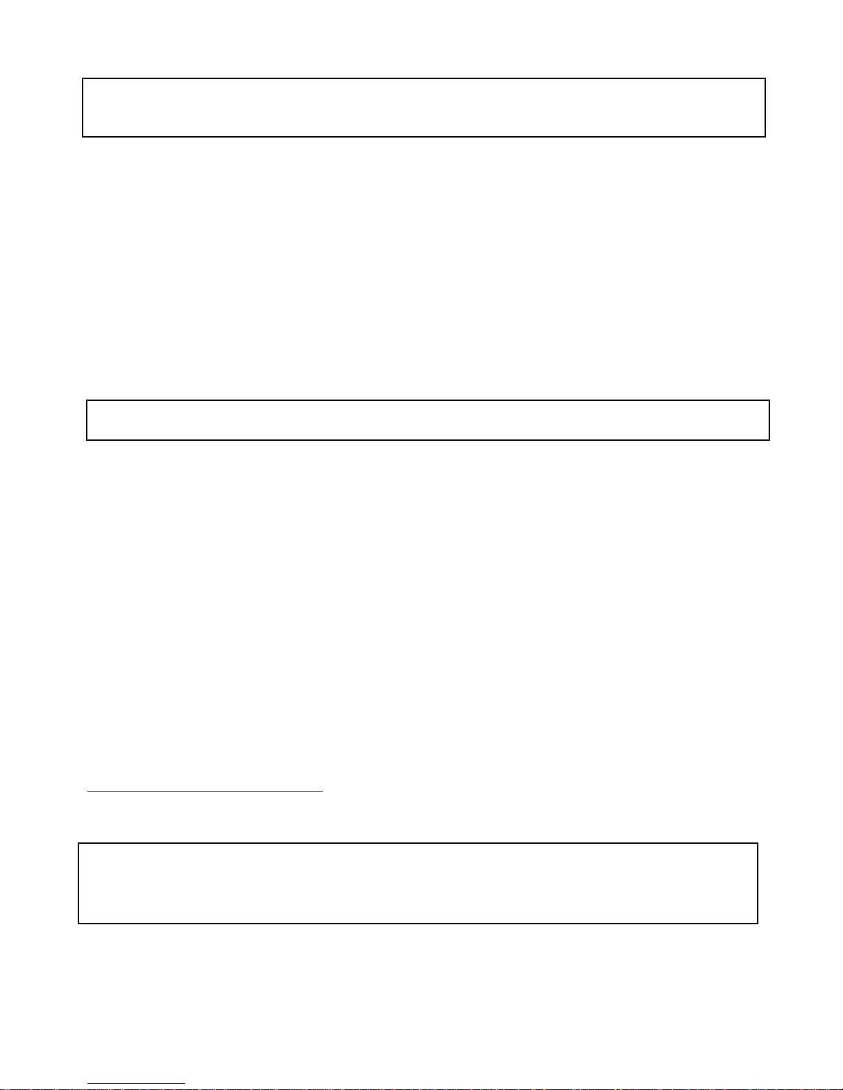
2. Fixture exterior view
3. Installation
3.1 Connection to mains
Fixtures must be installed by a qualified electrician in accordance with all national
and local electrical and construction codes and regulations.
This device falls under class one and must be grounded!
The ColorStrobe IP is equipped with auto-switching power supply that automatically adjusts to any 50-60Hz AC
power source from 100-240V (CE) or 100-277 V (US). The fixture must be connected to a non-dimmable power
source in order to avoid damage to its internal power supply and other electrical components.
Connect the fixture to the mains by means of inbuilt power cord with the plug.
1.
Head with LED array
2. Tilt lock
3. Base
4. Power and DMX connection
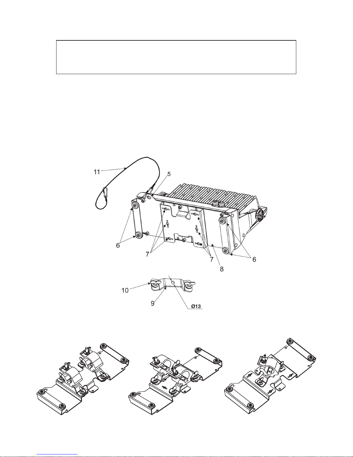
5. Attachment point for safety wire
6. Rubber feet
7. Openings for mounting adaptors Omega CL assembled
8. Universal base adaptor for Strobe IP
Page 6
ColorStrobe IP
6
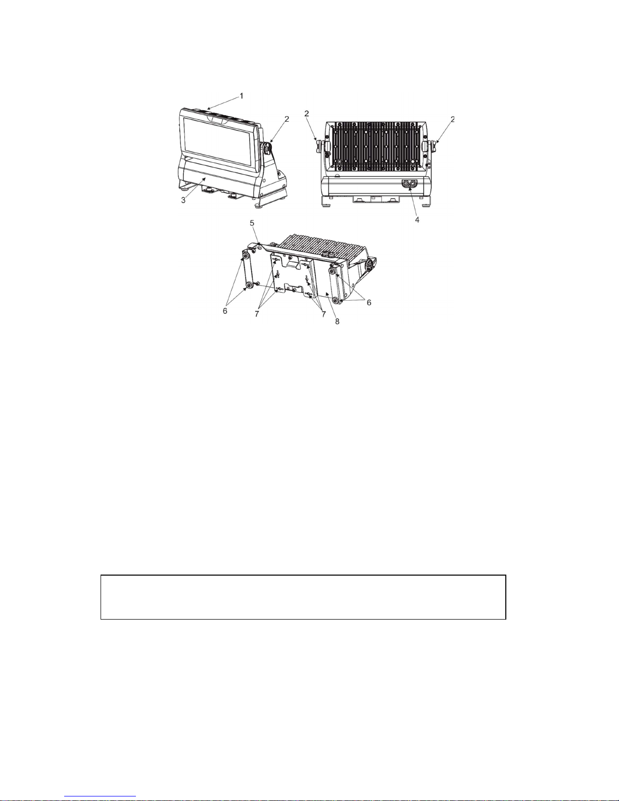
3.2 Mounting the fixture
Disconnect the fixture from mains prior to start any installation/assembly works.
The ColorStrobe IP can be arranged in any position/orientation without altering its operation characteristics. The
LED module can be tilted to desired position by means of the tilt lock.
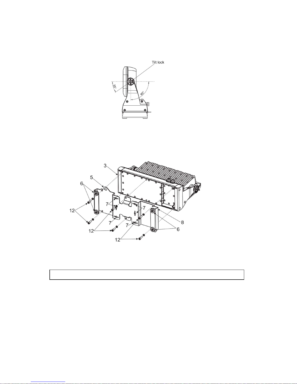
Universal base adaptor installation
Screw the universal base adaptor (8) to the base (3) of the fixture by means of six Allen head bolts M8x25 (12) with
six spring washers .
The Universal base adaptor of the fixture (8) is equipped with two pairs of rubber feet (6) for standing the fixture
on the floor and three pairs of openings (7) for installation of the mounting adaptors Omega CL (9) which allow to
rig the fixture to the truss.
For overhead installation, the fixture must be always secured with a safety wire.
A structure (truss) intended for installation of the fixture (s) must safely hold weight of the fixture(s) placed on it.
The structure has to be certificated to the purpose.
The operator has to make sure that safety-relating and machine-technical installations are approved by an expert
before taking into operation for the first time and after changes before taking into operation another time.
IMPORTANT! Overhead installation requires extensive experience including calculating working load limits,
installation material being used, and periodic safety inspection of all installation material and fixtures.
Fixtures may cause severe injuries when crashing down! If you have doubts concerning the safety of a possible
installation, do not install the fixtures and consult installation with an expert.
Page 7
ColorStrobe IP
7
CAUTION!
Use 2 mounting brackets Omega CL and appropriate clamps to rig the fixture on the truss.
Make sure that the device is fixed properly!
Ensure that the structure (truss) to which you are attaching the fixtures is secure
.
The fixture must never be fixed swinging freely in the room.
For securing the fixture to the truss, install a safety wire which can hold at least 10 times the weight of the fixture.
Use only the safety wire with a snap hook with screw lock gate.
Truss installation
1.Bolt clamp to the Omega adaptor CL (9) with M12 bolts and lock nuts through the hole in the adaptor
Omega CL.
2.Fasten the Omega adaptors (adaptor) CL on the universal base adaptor (8) by means of the quick-lock fasteners
(10) and tighten them fully clockwise.
3. Fasten the safety wire (11) in the attachment point (5) and around the truss.
Possible positions of the adaptors Omega adaptors CL with clamps:
2-bracket installation 2-bracket installation 1-bracket installation
Page 8
ColorStrobe IP
8
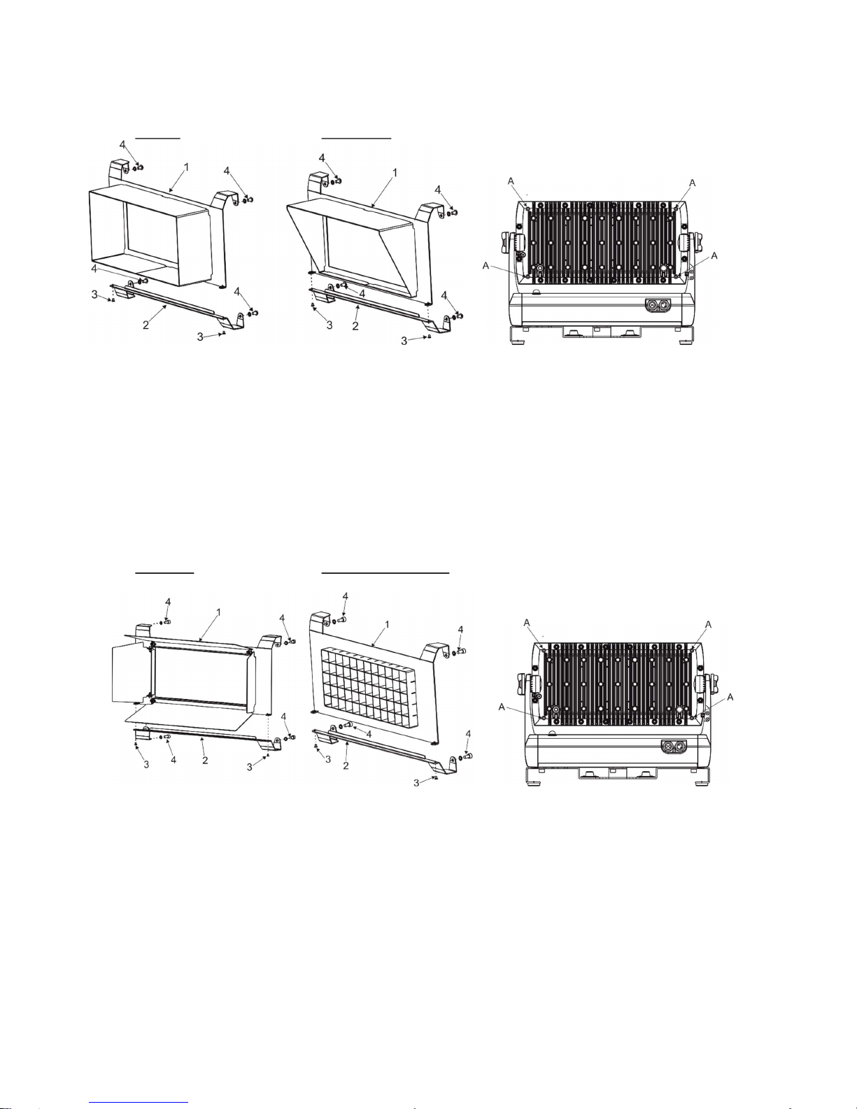
3.3 Top hat and half top hat installation
Top hat Half top hat
1. Unscrew screws M3x5 (3) to remove the bottom part (2) of the top hat (half top hat).
2. Place the upper part (1) of the top hat (half top hat) on the fixture head and secure it by means of two
screws M5x8 (4) with spring washers to the two threaded holes (A) on the back side of the fixture head.
3. Place the bottom part (2) of the top hat (half top hat) on the bottom part of the fixture head and screw it
back to the upper part (1) of the top hat (half top hat) by means of the screws M3x5 (3).
4. Secure the bottom part of the top hat (half top hat) to the fixture head by means of two screws M5x8 (4)
with spring washers to the two threaded holes (A) on the back side of the fixture head.
3.4 Barn door and Wire guard/anti-glare installation
Barn door Wire guard/anti-glare
1. Unscrew screws M3x5 (3) to remove the bottom part (2) of the barn door (wire guard/anti-glare).
2. Place the upper part (1) of the barn door (wire guard/anti-glare) on the fixture head and secure it by means
of two screws M5x10 (4) with spring washers to the two threaded holes (A) on the back side of the fixture
head.
3. Place the bottom part (2) of the barn door (wire guard/anti-glare) on the bottom part of the fixture head
and screw it back to the upper part (1) of the barn door (wire guard/anti-glare) by means of the screws
M3x5 (3).
4. Secure the bottom part of the barn door (wire guard/anti-glare) to the fixture head by means of two
screws M5x10 (4) with spring washers to the two threaded holes (A) on the back side of the fixture head.
Page 9
ColorStrobe IP
9
3.5 DMX 512 connection
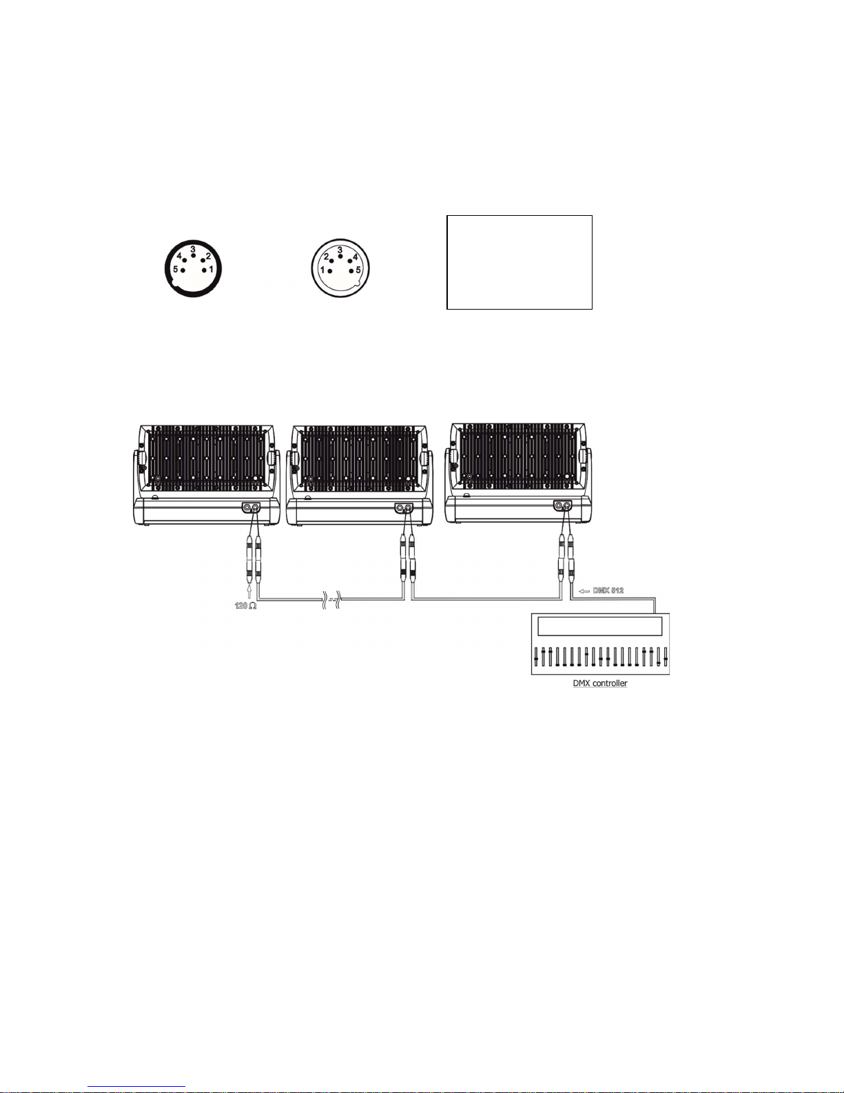
The fixture is equipped with 5-pin XLR connectors for DMX input/output. Only use a shielded twisted-pair cable
designed for RS-485 and 5-pin XLR connectors in order to connect the controller with the fixture or one fixture
with another.
Wiring of the XLR connectors:
XLR socket: XLR plug:
To build a DMX chain
1. Connect the DMX output of the controller directly with the DMX input of the first fixture in the DMX chain.
2. Connect the DMX output of the first fixture in the DMX chain with the DMX input of the next fixture.
3. Always connect the DMX output with the input of the next fixture until all fixtures are connected.
Do not overload the link. Max. 32 fixtures may be connected on a DMX link.
Caution: Terminate the link by installing a termination plug in the output of the last fixture. The termination plug is
a male 5-pin XLR plug (IP 66 rating) with a 120 Ohm resistor soldered between Signal (–) and Signal (+).
Warning:
Fixture´s XLR connectors are dust and water protected according to IP 67 by mating with related XLR cable
connectors.
They cannot stay disconnected outdoor. DMX output connector (XLR female) at the last fixture in a DMX line
has to be covered with the rubber cap before inserting a terminator. The rubber cap does not supply the
terminator.
The XLR terminator (male) has to be dust and water protected.
If the fixture is to be outdoor without connecting to DMX line, always interconnect its DMX input with DMX output
to keep declared IP rating of XLR connectors.
1 – Shield
2 - Signal (-)
3 - Signal (+)
4 – Not connected
5 – Not connected
Page 10
ColorStrobe IP
10
4. Control menu
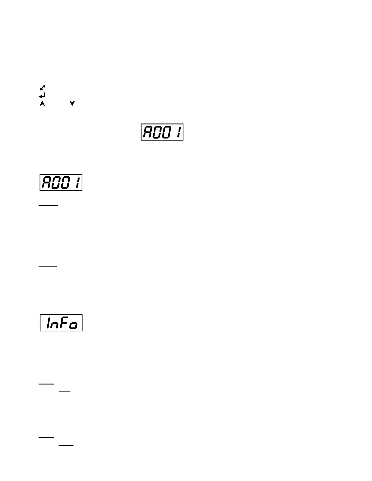
The ColorStrobe IP is equipped with a 4-segment LED display which allows you to set the fixture´s behaviour
according to your needs, obtain information on its operation, control all range of effects and program it
in stand-alone mode.
The four control buttons have the following functions:
- ESCAPE button-leaves menu without saving changes.
- ENTER button- enters menu, confirms adjusted values and leaves menu.
- UP and - DOWN buttons - move between menu items on the same level, sets values.
After switching the fixture on, display shows current DMX address.
4.1 Fixture Address
Use this menu to set the DMX address of the fixture.
dM.Ad. --- DMX addressing. Select this submenu to set a DMX start address.
To set a DMX address.
1. Press the ENTER button.
2. Use the UP/DOWN buttons to select desired start address.
3. Press the ENTER button to confirm the choice.
Note: After switching on, the ColorStrobe IP will automatically detect whether DMX 512 data is received or not.
If there is no data received at the DMX input, the display will start to flash the set address.
DM.Pr. --- DMX preset. Select this menu item to set a desired DMX mode.
4.2 Fixture information
Use this menu to read useful information about the fixture status.
To display desired information.
1. Press the ENTER button.
2. Use the UP/DOWN buttons to select the required menu item.
3. Press the ENTER button to confirm the choice.
Po.ti. --- Power On Time. Use the menu item to read the number of operation hours of the fixture.
totL - the function shows the total number of the operation hours since the ColorStrobe IP has been
fabricated.
rESEt - the function shows the number of the operation hours since the counter was last reset.
In order to reset this counter to 0, you have to press and hold the UP and DOWN buttons and at the same
time press the ENTER button.
VErS. ---Software Versions. Select this function to read the software version of the fixture processors.
ICI.b. --- display processor 1
Page 11
ColorStrobe IP
11
IC2.b. --- display processor 2
IC3.L. --- LED processor 3
IC4.L. --- LED processor 4
UiFi --- Wireless DMX module (if installed)
tEMP --- Fixture Temperatures. Select this menu to read the temperatures of the fixture:
bASE. --- temperature of the fixture inside
Cur.t. --- the current temperature of the fixture inside.
Hi.tE. --- the menu item shows the max. temperatures of the fixture inside since
the fixture has been fabricated.
rSEt --- the menu item shows the maximum temperatures of the fixture inside since the counter
was last reset. In order to reset this counter to 0 you have to press and hold the UP and DOWN
buttons and at the same time press the ENTER button.
LEdS. --- temperature of the LEDs PCB.
Cur.t. --- the current temperature of the LEDs PCB.
Hi.tE. --- the menu item shows the max. temperatures of the LEDs PCB since
the fixture has been fabricated.
rSEt --- the menu item shows the maximum temperatures of the LEDs PCB since the counter
was last reset. In order to reset this counter to 0 you have to press and hold the UP and DOWN
buttons and at the same time press the ENTER button.
Temperatures can be displayed in either °C or °F - see the option “tnP.u.“ in the menu “Pers“.
DM.In.---DMX values. Select this function to read DMX values of each channel received by the fixture.
4.3 Personality
Use this menu to modify the ColorStrobe IP operating behaviour.
DM.Pr. --- DMX preset. Select this menu item to set a desired DMX mode. Please refer to the chapter "DMX
protocol" for detail description of each DMX mode.
dM.In. --- DMX input. Select this menu item to select desired DMX input:
UirE --- Wired DMX.
UirL --- Wireless DMX
UrLo --- Wireless DMX –> wired DMX. The fixture receives wireless DMX signal and sends it to its
DMX output connector. Next fixtures can be connected to this fixture by DMX cable (fixture works
as a Wireless-DMX converter.
F.tin. --- Max. Fade time. Select this menu item to set a desired max. fade time (0-25.5 sec.). This adjusted fade
time influences fade of Red, Green, Blue,White and dimmer during DMX operation:
If time between two receiving DMX values is > than fade time set in the item “M Ftime“, the entire adjusted fade
time will be used.
If time between two receiving DMX values is < than fade time set in the item“M Ftime“, the adjusted fade time will
be reduced to fill entire time between the two receiving DMX values.
e.g “F.tin“=2sec. and fixture has received Red=0 DMX, after 5 seconds will receive from DMXcontroller Red=255
DMX. It means, that red will go to full intensity during 2 seconds.
“F.tin“=8 sec. and fixture has received Red=0 DMX, after 5 seconds will receive from DMX controller Red=255 DMX.
It means, that red will go to full intensity during 5 seconds. (Max, fade time is reduced from 8 sec. to 5 sec.).
Page 12
ColorStrobe IP
12
DiSP. --- Display adjusting. This function allows you to change the display settings.
d.On --- this function allows you to keep the display on or to turn off automatically 2 minutes
after last pressing any button on the control panel.
d.Int. --- select this function to adjust the display intensity (6-min.,100-max.).
turn ---
select this function to rotate menu 180 degrees from current orientation
.
C.CL.n. --- Colour calibration mode
.
If the function is on, white colours (2700K-8000K) are more uniform.
C.MI.n.
--- Colour mixing mode - This item allows switching into RGBW or CMY mode. In the CMY mode, white
channels are not active.
diM.c. --- Dimmer curve. Use the menuitem to set desired dimmer curve:
SqL --- Square law
Lin --- Linear
VhI.c. --- White counting. If this function is On, red, green and blue LEDs proportionally light when an intensity of a
white channel is increasing. If you want to light with white LEDs only, this function has to be set off.
Fo.bE. --- Foreground and background relation
SouEr --- Foreground overwrites Background
And --- Foreground and Background (standard behaviour of the fixture)
APLuS --- Foreground + Background
tnP.u. --- Temperature unit. Use this menu in order to display the fixture temperatures in desired units: °C or °F.
In.Po. --- Init effect positions. Use this function to set all effects to the desired positions to which they will move
after switching the fixture on (if DMX is not receiving).
dF.SE. --- Default Settings .The menu item sets all fixture parameters to the default (factory) values.
4.4 Manual mode
Use this menu to control all channels via buttons of the control board.
Items in this menu depend on selected DMX mode.
To control fixture channels.
1. Press the ENTER button.
2. Use the UP/DOWN buttons to select desired effect (channel).
List of control channels:
“rE.Fo” – a red LEDs saturation coarse- foreground
“rE.F.F” – a red LEDs saturation fine-foreground
“Gr.Fo” – a green LEDs saturation coarse -foreground
“Gr.F.F” – a green LEDs saturation fine-foreground
“bL.Fo” – a blue LEDs saturation coarse -foreground
“bL.F.F” – a blue LEDs saturation fine-foreground
“Uh.Fo” – a white LEDs saturation coarse -foreground
“Uh.F.F” – a white LEDs saturation fine-foreground
“Cto” – a colour temperature correction
“Vir.C” – a virtual colour
“di.Fo” – a dimmer coarse -foreground
“di.F.F” – a dimmer fine -foreground
Page 13

ColorStrobe IP
13
“dUrA.” – a duration
“rAtE.” – a rate
“SP.EF.” – special effects
“SP. FU.” – special functions
“rE.bG.” – a red LEDs saturation - background
“Gr.bG.” – a green LEDs saturation – background
“bL.bG.” – a blue LEDs saturation – background
“Vh.bG.” – a white LEDs saturation – background
“di.bG.” – a dimmer -background
“Zo.EF.” – zone effects
“Zo.SP.” – a zone effects speed
“rEd.1” – a red LEDs saturation- zone 1
“GrE.1” – a green LEDs saturation- zone 1
“bLU.1” – a blue LEDs saturation- zone 1
“UhI.1” – a white LEDs saturation- zone 1
“din.1” – a dimmer- zone 1
“dUr.1” – a duration – zone 1
“rAt.1” – a rate – zone 1
:
“GrE.6” – a green LEDs saturation- zone 6
“bLU.6” – a blue LEDs saturation- zone 6
“UhI.6” – a white LEDs saturation- zone 6
“din.6” – a dimmer- zone 6
“dUr.6” – a duration – zone 6
“rAt.6” – a rate – zone 6
Note: list of items depends on selected DMX mode.
3. Press the ENTER button and use the UP/DOWN buttons to set value , press the ENTER button to confirm it.
4. 5 Test sequences
Use this menu to run demo-test sequences without an external controller, which will show you some possibilities
of using the ColorStrobe IP.
4.6 Stand-alone setting
The fixtures on a data link are not connected to the controller but can execute pre-set programs which can be
different for every fixture. “Stand-alone operation” can be applied to the single fixture or to multiple fixtures
operating synchronously.
Auto. --- Automatic playback. This function allows you to select the program which will be played after switching
the fixture on. Selected program will be played continuously in a loop.
1. Use the UP/DOWN buttons to select test program (“tESt”), user program (“u.PrG”) or disable this function
(OFF).
2. Press the ENTER button to confirm the choice.
PLAY --- Playing program. Entering this menu provides a complete overview of all programs offered, from which
the selected program can run.
1. Use the UP/DOWN buttons to select desired program.
Page 14

ColorStrobe IP
14
2. Press the ENTER button. The selected program runs in a loop.
Edit --- Editing a program. The fixture offers a freely editable program up to 40 steps. Every program step includes
a step time-the total time occupied by the step in the program.
1. Use the UP/DOWN buttons to select a desired program step ("St. 1" - "St.40") and press ENTER button.
2. Use the UP/DOWN buttons to select a channel you want to edit and press the ENTER button.
List of editable items:
“P.End” - a total number of the program steps (value 1-40). This value should be set before start of
programming (e.g. if you want to create a program with 10 steps, set P.End=10).
“rE.Fo” – a red LEDs saturation coarse- foreground
“Gr.Fo” – a green LEDs saturation coarse -foreground
“bL.Fo” – a blue LEDs saturation coarse -foreground
“Uh.Fo” – a white LEDs saturation coarse -foreground
“Cto” – a colour temperature correction
“Vir.C” – a virtual colour
“di.Fo” – a dimmer coarse -foreground
“dUrA.” – a duration
“rAtE.” – a rate
“SP.EF.” – special effects
“SP. FU.” – special functions
“rE.bG.” – a red LEDs saturation - background
“Gr.bG.” – a green LEDs saturation – background
“bL.bG.” – a blue LEDs saturation – background
“Vh.bG.” – a white LEDs saturation – background
“Zo.EF.” – zone effects
“Zo.SP.” – a zone effects speed
“F.tin.” – fade time
“S.tin” – step time
“COPY“. – this item duplicates current prog. step to the next prog. step.
Note: Items in this menu depend on selected DMX mode.
3. Use the UP/DOWN buttons to set a DMX value of the channel and then press the ENTER button.
4. Use the UP/DOWN buttons to select next channel and press the ENTER button.
5. After having set all channels in the current program step, press the ESCAPE button to go one menu level
back and select another program step.
4.7 Special functions
rdM.L --- Code.This menu item shows the first part of the RDM identification code.
rdM.H --- Code. This menu item shows the second part of the RDM identification code.
ViFi --- Wireless DMX. The menu serves for reading of the wireless operation status (only for Wireless DMX
version).
50 --- Wireless DMX signal intensity. The menu item shows level of received signal in %. If the fixture is not
linked to the transmitter, “niSS” is displayed.
UnLI --- Wireless DMX unlink. The item serves for unlinking the fixture from transmitter.
Page 15

ColorStrobe IP
15
uPd.M. --- Updating mode. The menu item allows you to update software in the fixture via either serial or USB port
of PC.
The following are required in order to update software:
- PC running Windows 7/8/10 or Linux
- DMX Software Uploader
- Flash cable RS232/DMX P/N.13050624 (if you want to use serial port of PC)
- Robe Universal Interface (if you want to use USB port of PC)
Note: Software update should be executed by a qualified person. If you lack qualification, do not attempt the
update yourself and ask for help from your Robe distributor.
DMX address, user program and all items in the menu "PerS" will be set to their default (factory) values.
To update software in the fixture:
I. Installation of the DMX Software Uploader.
1. DMX Software Uploader program is available from the Robe web site at WWW.robe.cz.
2. Make a new directory ( e.g. Robe Uploader) on your hard disk and download the software to it.
3. Unpack the program to the directory.
II. Fixture software updating.
1.Determine which of your ports is available on your PC and connect it:
- with the DMX input of the fixture if you are using the flash cable RS232/DMX
- with the DMX output of the Robe Universal Interface if you are using the USB cable.
Disconnect the fixture from the other fixtures in the DMX chain. Turn both the computer and
the fixture on. Make sure the lamp is switched off (only if the fixture involves a lamp).
2. Switch the fixture to the updating mode by selecting the "uPd.M." item and then selecting “yES“.
Note: If you do not want to continue in software update, you have to switch the fixture off and on
to escape from this menu.
We recommend canceling all running programs before starting the Software Uploader.
3. Run the Software Uploader program. Select desired COM and then click on the Connect button.
(Select COM if the serial port is used or Robe Universal Interface if the USB port is used).
If the connection is OK, click on the “Start Uploading button“ to start uploading. It will take several
minutes to perform software update.
If the option "Incremental Update" is not checked, all processors will be updated (including
processors with the same software version).
If you wish to update only later versions of processors, check the “Incremental Update box“.
Avoid interrupting the process. Update status is being displayed in the Info Box window.
When the update is finished, the line with the text “The fixture is successfully updated“ will appear in
this window and the fixture will reset with the new software.
Note: In case upload process is interrupted (e.g. power loss), the fixture stays in “Updating mode” and you will
have to repeat the software update again.
Page 16

ColorStrobe IP
16
5. Strobe and Special effects running
5.1 Strobe
Mode 1 and 2
Mode 3 and 4
5.2 Special effects
Rumping
Rump Up
Page 17

ColorStrobe IP
17
Rump Down
Rump Up/Down
Lightning
Mode 1, 2, 4
Page 18

ColorStrobe IP
18
Spikes
For Duration and Rate timing serves the same values as for strobe
Page 19

ColorStrobe IP
19
6. Technical specifications
Power supply
• Electronic auto-ranging
• Input voltage (EU): 100 - 240V AC, 50-60 Hz
• Input voltage (US): 100 - 277V AC, 50-60 Hz
• Max. power consumption: 440W
• Inrush current: 20A (at 230V), 30A (at 115V)
Optic & Effects
• Light source: 60 x high power RGBW multichip LED
• Beam angle: 35°
• 6 LED zones
• Min. LED life expectancy: 20,000 hours
Virtual colour wheel
• 237 colours including whites (2700K, 3200K, 4200K, 5600K and 8000K)
• Halogen lamp effect at whites 2700K and 3200K Rainbow effect with in both directions with variable
speed
Zone effects
•Zone effects in both directions with variable speed
Strobe
•Strobe effect with variable speed
•Pulses adjustment: frequency, duration, intensity
•Special effects: rump up, rump down, rump up/down, random, lighting, spikes
Dimmer
• Smooth 16-bit dimming from 0 - 100 %
Control
• Setting & Addressing: 4-segment LED display & 4 control buttons
• Control: USITT DMX 512 (RDM support)
• DMX protocol modes: 5 (9,14,18,28, 42 control channels)
• Operations modes: DMX, Stand-alone
• Manual control of all effects via control panel
• One editable program, up to 40 steps
Wireless DMX/RDM module (only for wireless DMX version of the Strobe IP)
• Compliance with USITT DMX-512 (1986 & 1990) and 512-A
• Full DMX fidelity and frame integrity
• Auto sensing of DMX frame rate and frame size
• <5ms DMX latency
• Operational frequency range of 2402-2480 MHz
• Producer: LumenRadio
Connection
• 2x Outdoor DMX cable CA-0611 + 2x 5-pin XLR (male,female IP 67)
• 1x mains cable with plug
Mounting
• via Universal base adaptor for Strobe IP
Page 20

ColorStrobe IP
20
Protection factor
• EU: IP 67 (except power plug)
• US: Suitable for wet location (except power plug)
Temperatures
• Operating Ambient Temperature: -20°C / +40°C (-4°F / +104°F )
• Operating Temperature: +75°C @ Ambient +40°C (+167°F @ Ambient +104°F )
Minimum distances
• Min. distance from flammable surfaces: 0.3 m
• Min. distance of illuminated objects: 2 m
Total heat dissipation
• 1500 BTU/h (calculated)
Weight
• 15.3 kg
Dimensions
mm [inch]
Page 21

ColorStrobe IP
21
Photometric diagrams
Included items
• 1 x Strobe IP
• 1 x Universal base adaptor for Strobe IP (P/N 10980379)
• 1 x User manual
OptionaI accessories
• Top Hat Strobe IP black (P/N 10980354)
• Half Top Hat Strobe IP black (P/N 10980355)
• Wire Guard/Anti-Glare Strobe IP (P/N 10980385)
• Barndoor Module Strobe IP/Divine 60 black (10980356)
• Barndoor Module Strobe IP/Divine 60 silver (10980389)
• Gel Frame Strobe IP black (10980364)
• Set of Rubber Feet black (P/N 10980370)
• Omega adaptor CL-regular 2 pcs in box (P/N 10980033)
• Doughty Trigger Clamp (P/N (17030386)
• Safety wire 35kg (P/N 99011963)
Page 22

ColorStrobe IP
22
7. Cleaning and maintenance
DANGER !
Disconnect from the mains before starting any cleaning or maintenance work
Rinse off loose dirt with low pressure water spray. Wash the housing with a soft brush or sponge and a mild, nonabrasive washing detergent. Rinse it.
Maintenance and service operations are only to be carried out by a qualified person.
Should you need any spare parts, please use genuine parts.
7.1 Replacing a fuse
This replacement has to be realized by a qualified person or Robe service worker only.
7.2 Disposing of the product
To preserve the environment please dispose or recycle this product at the end of its life according to the local
regulations and codes.
Specifications are subject to change without notice
January 5, 2018
Copyright © 2017-2018 Robe Lighting - All rights reserved
Made in CZECH REPUBLIC by ROBE LIGHTING s.r.o. Palackeho 416/20 CZ 75701 Valasske Mezirici
Page 23

DMX protocol
Version: 1.1
1 2 3 4 5
1 1 1 * *
Red/Cyan foreground (8 bit)- all zones
0 - 255 Red orCyan colour saturation control - coarse (0-100%) proportional
* 2 * * *
Red/Cyan foreground (16bit)- all zones
0 - 255 Red or Cyan colour saturation control - fine proportional
2 3 2 * *
Green/Magenta foreground (8-bit) - all zones
0 - 255 Green or Magenta colour saturation control - coarse (0-100%) proportional
* 4 * * *
Green/Magenta foreground (16bit) - all zones
0 - 255 Green or Magenta colour saturation control - fine proportional
3 5 3 * *
Blue/Yellow foreground (8 bit) - all zones
0 - 255 Blue or Yellow colour saturation control - coarse (0-100%) proportional
* 6 * * *
Blue/Yellow foreground (16bit) -all zones
0 - 255 Blue or Yellow colour saturation control - fine proportional
4 7 4 * *
White foreground (8 bit) - all zones
0-255 White colour saturation control - coarse (0-100%) -RGBW mode only proportional
* 8 * * *
White foreground (16 bit) - all zones
0 - 255 White colour saturation control - fine (RGBW mode only) proportional
5 9 5 * *
CTC
0 No function step
1-255 Col. temperature correction proportional
6 10 6 * *
Virtual colour wheel
0 No function step
1-2 White 2700 K step
3 White 2700 K (Halogen lamp mode)* step
4-5 White 3200 K step
6 White 3200 K (Halogen lamp mode)* step
7-9 White 4200 K step
10-12 White 5600 K step
13-15 White 8000 K step
16 Blue (Blue=full, Red+Green+White=0) step
17-55 Red=0, Green->up,Blue =full, White=0 proportional
56 Light Blue (Red=0, Green=full, Blue =full, White=0) step
57 - 95 Red=0, Green=full, Blue->down, White=0 proportional
96 Green (Red=0, Green=full, Blue =0, White=0) step
97 – 134 Red->up, Green=full, Blue=0, White=0 proportional
135 Yellow (Red=full, Green=full, Blue=0, White=0) step
136 - 174 Red=full, Green->down, Blue=0, White=0 proportional
175 Red(Red=full, Green=0, Blue=0, White=0) step
176 -214 Red=full, Green=0, Blue->up, White=0 proportional
215 Magenta (Red=full, Green=0, Blue=full, White=0) step
216 - 246 Red -> down, Green=0, Blue=full, White=0 proportional
247 Blue (Red=0, Green=0, Blue=full, White=0) step
248-251 Rainbow effect (with fade time)from slow-> fast proportional
252-255 Rainbow effect(without fade time) from slow-> fast proportional
7 11 7 * *
Intensity foreground (8bit)-all zones
ColorStrobe IP - DMX protocol
Mode 1 –RGBW mode , Mode 2 –full RGBW , Mode 3 –Zone effect mode , Mode 4 – 3-zone mode, Mode 5 – 6-zone mode
Mode/channel
DMX
value
Function
Type of
control
Page 1
Page 24

DMX protocol
1 2 3 4 5
Mode/channel
DMX
value
Function
Type of
control
0-255 Coarse intensity from min. to max. proportional
* 12 * * *
Intensity foreground (16bit)-all zones
0-255 Fine intensity from min. to max. proportional
8 13 8 * *
Duration
0-255 Light time duration from min. —>max. step
9 14 9 * *
Rate
0-5 No flash step
6-255 Flash frequency from min. —>max step
Note: Duration time<Rate: flashing
Duration time>= Rate: Light continuously On
* * 10 * *
Special effects
0-1 No function step
2-5 Permanent lightening step
6-42
Ramp up (use channels Duration and Rate for control)
step
43-85
Ramp down (use channels Duration and Rate for control)
step
86-128
Ramp up/down
(use channels Duration and Rate for control)
step
129-171
Random strobe (use channel Rate for control)
step
172-214
Lightning (use channel Rate for control)
step
215-255
Spikes (use channels Duration and Rate for control)
step
* * 11 * *
Special Functions
0 -19 Reserved
To activate following functions , stop in DMX value for at least 3
sec. Corresponding menu items are temporarily overrided.
20-24
Display On
step
25-29
Display Off
step
30-34
RGBW colour mixing mode
step
35-39
CMY colour mixing mode
step
40-44
Colour calibration On
step
45-49
Colour calibration Off
step
50-54
Foreground overwrites Background
step
55-59
Foreground + Background
step
60-64
Foreground and Background - standard (default) behaviour
step
65-74
Reserved
75-79 White counting On step
80-84 White counting Off step
85-89
Dimmer curve: linear
step
90-94
Dimmer curve: square law
step
95-255
Reserved
* * 12 * *
Red/Cyan Background (8 bit)- all zones
0 - 255 Red or Cyan colour saturation control - coarse (0-100%) proportional
* * 13 * *
Green/Magenta Background (8 bit) - all zones
0 - 255 Green or Magenta colour saturation control - coarse (0-100%) proportional
* * 14 * *
Blue/Yellow Background (8 bit) - all zones
0 - 255 Blue or Yellow colour saturation control - coarse (0-100%) proportional
* * 15 * *
White Background (8 bit) - all zones
0-255 White colour saturation control - coarse (0-100%)-only RGBW mode proportional
* * 16 * *
Intensity Background (8bit)-all zones
Page 2
Page 25

DMX protocol
1 2 3 4 5
Mode/channel
DMX
value
Function
Type of
control
0-255 Coarse intensity from min. to max. proportional
* * 17 * *
Zone Effects
0-2
No function
step
3-4 Effect 1 step
5-6 Effect 2 step
7-8 Effect 3 step
9-10 Effect 4 step
11-12 Effect 5 step
13-14 Effect 6 step
15-16 Effect 7 step
17-18 Effect 8 step
19-20 Effect 9 step
21-22 Effect 10 step
23-24 Effect 11 step
25-26 Effect 12 step
27-28 Effect 13 step
29-30 Effect 14 step
31-32 Effect 15 step
33-34 Effect 16 step
35-36 Effect 17 step
37-38 Effect 18 step
39-40 Effect 19 step
41-42 Effect 20 step
43-44 Effect 21 step
45-46 Effect 22 step
47-48 Effect 23 step
49-50 Effect 24 step
51-52 Effect 25 step
53-255 Raw DMX step
* * 18 * * Zone Effects Speed
0-63 Speed from min. —>max. without fade time proportional
64-127 Speed from max. —>min. without fade time (op. direction) proportional
128-191 Speed from min. —>max. with fade time proportional
192-255 Speed from max. —>min. with fade time (op. direction) proportional
* * * 1 1 Red intensity (8bit)-zone 1
0-255 Coarse red intensity from 0% to 100% proportional
* * * 2 2 Green intensity (8bit)-zone 1
0-255 Coarse green intensity from 0% to 100% proportional
* * * 3 3 Blue intensity (8bit)-zone 1
0-255 Coarse blue intensity from 0% to 100% proportional
* * * 4 4 White intensity (8bit)-zone 1
0-255 Coarse white intensity from 0% to 100% proportional
* * * 5 5 Intensity (8bit)-zone 1
0-255 Coarse intensity from 0% to 100% proportional
* * * 6 6 Duration - zone 1
0-255 Light time duration from min. —>max. step
* * * 7 7 Rate - zone 1
0-5 No flash step
Page 3
Page 26

DMX protocol
1 2 3 4 5
Mode/channel
DMX
value
Function
Type of
control
6-255 Flash frequency from min. —>max step
* * * 8 8 Red intensity (8bit)-zone 2
0-255 Coarse red intensity from 0% to 100% proportional
* * * 9 9 Green intensity (8bit)-zone 2
0-255 Coarse green intensity from 0% to 100% proportional
* * * 10 10 Blue intensity (8bit)-zone 2
0-255 Coarse blue intensity from 0% to 100% proportional
* * * 11 11 White intensity (8bit)-zone 2
0-255 Coarse white intensity from 0% to 100% proportional
* * * 12 12 Intensity (8bit)-zone 2
0-255 Coarse intensity from 0% to 100% proportional
* * * 13 13 Duration - zone 2
0-255 Light time duration from min. —>max. step
* * * 14 14 Rate - zone 2
0-5 No flash step
6-255 Flash frequency from min. —>max step
* * * 15 15 Red intensity (8bit)-zone 3
0-255 Coarse red intensity from 0% to 100% proportional
* * * 16 16 Green intensity (8bit)-zone 3
0-255 Coarse green intensity from 0% to 100% proportional
* * * 17 17 Blue intensity (8bit)-zone 3
0-255 Coarse blue intensity from 0% to 100% proportional
* * * 18 18 White intensity (8bit)-zone 3
0-255 Coarse white intensity from 0% to 100% proportional
* * * 19 19 Intensity (8bit)-zone 3
0-255 Coarse intensity from 0% to 100% proportional
* * * 20 20 Duration - zone 3
0-255 Light time duration from min. —>max. step
* * * 21 21 Rate - zone 3
0-5 No flash step
6-255 Flash frequency from min. —>max step
* * * * 22 Red intensity (8bit)-zone 4
0-255 Coarse red intensity from 0% to 100% proportional
* * * * 23 Green intensity (8bit)-zone 4
0-255 Coarse green intensity from 0% to 100% proportional
* * * * 24 Blue intensity (8bit)-zone 4
0-255 Coarse blue intensity from 0% to 100% proportional
* * * * 25 White intensity (8bit)-zone 4
0-255 Coarse white intensity from 0% to 100% proportional
* * * * 26 Intensity (8bit)-zone 4
0-255 Coarse intensity from 0% to 100% proportional
* * * * 27 Duration - zone 4
0-255 Light time duration from min. —>max. step
* * * * 28 Rate - zone 4
0-5 No flash step
6-255 Flash frequency from min. —>max step
* * * * 29 Red intensity (8bit)-zone 5
0-255 Coarse red intensity from 0% to 100% proportional
Page 4
Page 27

DMX protocol
1 2 3 4 5
Mode/channel
DMX
value
Function
Type of
control
* * * * 30 Green intensity (8bit)-zone 5
0-255 Coarse green intensity from 0% to 100% proportional
* * * * 31 Blue intensity (8bit)-zone 5
0-255 Coarse blue intensity from 0% to 100% proportional
* * * * 32 White intensity (8bit)-zone 5
0-255 Coarse white intensity from 0% to 100% proportional
* * * * 33 Intensity (8bit)-zone 5
0-255 Coarse intensity from 0% to 100% proportional
* * * * 34 Duration - zone 5
0-255 Light time duration from min. —>max. step
* * * * 35 Rate - zone 5
0-5 No flash step
6-255 Flash frequency from min. —>max step
* * * * 36 Red intensity (8bit)-zone 6
0-255 Coarse red intensity from 0% to 100% proportional
* * * * 37 Green intensity (8bit)-zone 6
0-255 Coarse green intensity from 0% to 100% proportional
* * * * 38 Blue intensity (8bit)-zone 6
0-255 Coarse blue intensity from 0% to 100% proportional
* * * * 39 White intensity (8bit)-zone 6
0-255 Coarse white intensity from 0% to 100% proportional
* * * * 40 Intensity (8bit)-zone 6
0-255 Coarse intensity from 0% to 100% proportional
* * * * 41 Duration - zone 6
0-255 Light time duration from min. —>max. step
* * * * 42 Rate - zone 6
0-5 No flash step
6-255 Flash frequency from min. —>max step
* In the Halogen lamp mode the Dimmer channel imitates behaviour of the halogen lamp during dimming
Order of zones (front view) :
Mode 1,2,3
Mode 4
Mode 5
Copyright © 2017 Robe Lighting s.r.o. - All rights reserved
All Specifications subject to change without notice
Page 5
Page 28

Strobe Duration
50 and 60 Hz 50Hz 60Hz 50Hz 60Hz 50Hz 60Hz
[ms] [ms] [ms] [Hz] [Hz] [ms] [ms]
0
13,31
x x x x 2600,00 2166,67
1
16,64
x x x x 2600,00 2166,67
2
19,97
x x x x 2580,00 2150,00
3
23,30
x x x x 2580,00 2150,00
4
26,62
x x x x 2560,00 2133,34
5
29,95
x x x x 2560,00 2133,34
6
33,28
3460,00 2883,34 0,289 0,347 2540,00 2116,67
7
36,61
2880,00 2400,00 0,347 0,417 2540,00 2116,67
8
39,94
2320,00 1933,34 0,431 0,517 2520,00 2100,00
9
43,26
2020,00 1683,34 0,495 0,594 2520,00 2100,00
10
46,59
1740,00 1450,00 0,575 0,690 2500,00 2083,34
11
49,92
1560,00 1300,00 0,641 0,769 2500,00 2083,34
12
53,25
1400,00 1166,67 0,714 0,857 2480,00 2066,67
13
56,58
1280,00 1066,67 0,781 0,937 2480,00 2066,67
14
59,90
1160,00 966,67 0,862 1,034 2460,00 2050,00
15
63,23
1080,00 900,00 0,926 1,111 2460,00 2050,00
16
66,56
1000,00 833,34 1,000 1,200 2440,00 2033,34
17
69,89
940,00 783,33 1,064 1,277 2440,00 2033,34
18
73,22
880,00 733,33 1,136 1,364 2420,00 2016,67
19
76,54
820,00 683,33 1,220 1,463 2420,00 2016,67
20
79,87
780,00 650,00 1,282 1,538 2400,00 2000,00
21
83,20
740,00 616,67 1,351 1,622 2400,00 2000,00
DMX
Strobe Rate Strobe Rate Lightning Rate
22
86,53
700,00
583,33
1,429
1,714
2380,00
1983,34
23
89,86
660,00 550,00 1,515 1,818 2380,00 1983,34
24
93,18
640,00 533,33 1,563 1,875 2360,00 1966,67
25
96,51
600,00 500,00 1,667 2,000 2360,00 1966,67
26
99,84
580,00 483,33 1,724 2,069 2340,00 1950,00
27
103,17
560,00 466,67 1,786 2,143 2340,00 1950,00
28
106,50
540,00 450,00 1,852 2,222 2320,00 1933,34
29
109,82
520,00 433,33 1,923 2,308 2320,00 1933,34
30
113,15
500,00 416,67 2,000 2,400 2300,00 1916,67
31
116,48
480,00 400,00 2,083 2,500 2300,00 1916,67
32
119,81
480,00 400,00 2,083 2,500 2280,00 1900,00
33
123,14
460,00 383,33 2,174 2,609 2280,00 1900,00
34
126,46
440,00 366,67 2,273 2,727 2260,00 1883,34
35
129,79
420,00 350,00 2,381 2,857 2260,00 1883,34
36
133,12
420,00 350,00 2,381 2,857 2240,00 1866,67
37
136,45
400,00 333,33 2,500 3,000 2240,00 1866,67
38
139,78
400,00 333,33 2,500 3,000 2220,00 1850,00
39
143,10
380,00 316,67 2,632 3,158 2220,00 1850,00
40
146,43
380,00 316,67 2,632 3,158 2200,00 1833,34
41
149,76
360,00 300,00 2,778 3,333 2200,00 1833,34
42
153,09
360,00 300,00 2,778 3,333 2180,00 1816,67
43
156,42
340,00 283,33 2,941 3,529 2180,00 1816,67
44
159,74
340,00 283,33 2,941 3,529 2160,00 1800,00
45
163,07
320,00 266,67 3,125 3,750 2160,00 1800,00
Page 29

Strobe Duration
50 and 60 Hz 50Hz 60Hz 50Hz 60Hz 50Hz 60Hz
[ms] [ms] [ms] [Hz] [Hz] [ms] [ms]
DMX
Strobe Rate Strobe Rate Lightning Rate
46
166,40
320,00 266,67 3,125 3,750 2140,00 1783,34
47
169,73
320,00 266,67 3,125 3,750 2140,00 1783,34
48
173,06
320,00 266,67 3,125 3,750 2120,00 1766,67
49
176,38
300,00 250,00 3,333 4,000 2120,00 1766,67
50
179,71
300,00 250,00 3,333 4,000 2100,00 1750,00
51
183,04
280,00 233,33 3,571 4,286 2100,00 1750,00
52
186,37
280,00 233,33 3,571 4,286 2080,00 1733,34
53
189,70
260,00 216,67 3,846 4,615 2080,00 1733,34
54
193,02
260,00 216,67 3,846 4,615 2060,00 1716,67
55
196,35
260,00 216,67 3,846 4,615 2060,00 1716,67
56
199,68
260,00 216,67 3,846 4,615 2040,00 1700,00
57
203,01
240,00 200,00 4,167 5,000 2040,00 1700,00
58
206,34
240,00 200,00 4,167 5,000 2020,00 1683,34
59
209,66
240,00 200,00 4,167 5,000 2020,00 1683,34
60
212,99
240,00 200,00 4,167 5,000 2000,00 1666,67
61
216,32
220,00 183,33 4,545 5,455 2000,00 1666,67
62
219,65
220,00 183,33 4,545 5,455 1980,00 1650,00
63
222,98
220,00 183,33 4,545 5,455 1980,00 1650,00
64
226,30
220,00 183,33 4,545 5,455 1960,00 1633,34
65
229,63
220,00 183,33 4,545 5,455 1960,00 1633,34
66
232,96
220,00 183,33 4,545 5,455 1940,00 1616,67
67
236,29
200,00 166,67 5,000 6,000 1940,00 1616,67
68
239,62
200,00 166,67 5,000 6,000 1920,00 1600,00
69
242,94
200,00
166,67
5,000
6,000
1920,00
1600,00
70
246,27
200,00 166,67 5,000 6,000 1900,00 1583,34
71
249,60
200,00 166,67 5,000 6,000 1900,00 1583,34
72
252,93
200,00 166,67 5,000 6,000 1880,00 1566,67
73
256,26
200,00 166,67 5,000 6,000 1880,00 1566,67
74
259,58
200,00 166,67 5,000 6,000 1860,00 1550,00
75
262,91
180,00 150,00 5,556 6,667 1860,00 1550,00
76
266,24
180,00 150,00 5,556 6,667 1840,00 1533,34
77
269,57
180,00 150,00 5,556 6,667 1840,00 1533,34
78
272,90
180,00 150,00 5,556 6,667 1820,00 1516,67
79
276,22
180,00 150,00 5,556 6,667 1820,00 1516,67
80
279,55
180,00 150,00 5,556 6,667 1800,00 1500,00
81
282,88
180,00 150,00 5,556 6,667 1800,00 1500,00
82
286,21
180,00 150,00 5,556 6,667 1780,00 1483,34
83
289,54
160,00 133,33 6,250 7,500 1780,00 1483,34
84
292,86
160,00 133,33 6,250 7,500 1760,00 1466,67
85
296,19
160,00 133,33 6,250 7,500 1760,00 1466,67
86
299,52
160,00 133,33 6,250 7,500 1740,00 1450,00
87
302,85
160,00 133,33 6,250 7,500 1740,00 1450,00
88
306,18
160,00 133,33 6,250 7,500 1720,00 1433,34
89
309,50
160,00 133,33 6,250 7,500 1720,00 1433,34
90
312,83
160,00 133,33 6,250 7,500 1700,00 1416,67
91
316,16
140,00 116,67 7,143 8,571 1700,00 1416,67
92
319,49
140,00 116,67 7,143 8,571 1680,00 1400,00
Page 30

Strobe Duration
50 and 60 Hz 50Hz 60Hz 50Hz 60Hz 50Hz 60Hz
[ms] [ms] [ms] [Hz] [Hz] [ms] [ms]
DMX
Strobe Rate Strobe Rate Lightning Rate
93
322,82
140,00 116,67 7,143 8,571 1680,00 1400,00
94
326,14
140,00 116,67 7,143 8,571 1660,00 1383,34
95
329,47
140,00 116,67 7,143 8,571 1660,00 1383,34
96
332,80
140,00 116,67 7,143 8,571 1640,00 1366,67
97
336,13
140,00 116,67 7,143 8,571 1640,00 1366,67
98
339,46
140,00 116,67 7,143 8,571 1620,00 1350,00
99
342,78
140,00 116,67 7,143 8,571 1620,00 1350,00
100
346,11
140,00 116,67 7,143 8,571 1600,00 1333,34
101
349,44
140,00 116,67 7,143 8,571 1600,00 1333,34
102
352,77
140,00 116,67 7,143 8,571 1580,00 1316,67
103
356,10
120,00 100,00 8,333 10,000 1580,00 1316,67
104
359,42
120,00 100,00 8,333 10,000 1560,00 1300,00
105
362,75
120,00 100,00 8,333 10,000 1560,00 1300,00
106
366,08
120,00 100,00 8,333 10,000 1540,00 1283,34
107
369,41
120,00 100,00 8,333 10,000 1540,00 1283,34
108
372,74
120,00 100,00 8,333 10,000 1520,00 1266,67
109
376,06
120,00 100,00 8,333 10,000 1520,00 1266,67
110
379,39
120,00 100,00 8,333 10,000 1500,00 1250,00
111
382,72
120,00 100,00 8,333 10,000 1500,00 1250,00
112
386,05
120,00 100,00 8,333 10,000 1480,00 1233,34
113
389,38
120,00 100,00 8,333 10,000 1480,00 1233,34
114
392,70
120,00 100,00 8,333 10,000 1460,00 1216,67
115
396,03
120,00 100,00 8,333 10,000 1460,00 1216,67
116
399,36
120,00
100,00
8,333
10,000
1440,00
1200,00
117
402,69
120,00 100,00 8,333 10,000 1440,00 1200,00
118
406,02
120,00 100,00 8,333 10,000 1420,00 1183,34
119
409,34
100,00 83,33 10,000 12,000 1420,00 1183,34
120
412,67
100,00 83,33 10,000 12,000 1400,00 1166,67
121
416,00
100,00 83,33 10,000 12,000 1400,00 1166,67
122
419,33
100,00 83,33 10,000 12,000 1380,00 1150,00
123
422,66
100,00 83,33 10,000 12,000 1380,00 1150,00
124
425,98
100,00 83,33 10,000 12,000 1360,00 1133,34
125
429,31
100,00 83,33 10,000 12,000 1360,00 1133,34
126
432,64
100,00 83,33 10,000 12,000 1340,00 1116,67
127
435,97
100,00 83,33 10,000 12,000 1340,00 1116,67
128
439,30
100,00 83,33 10,000 12,000 1320,00 1100,00
129
442,62
100,00 83,33 10,000 12,000 1320,00 1100,00
130
445,95
100,00 83,33 10,000 12,000 1300,00 1083,34
131
449,28
100,00 83,33 10,000 12,000 1300,00 1083,34
132
452,61
100,00 83,33 10,000 12,000 1280,00 1066,67
133
455,94
100,00 83,33 10,000 12,000 1280,00 1066,67
134
459,26
100,00 83,33 10,000 12,000 1260,00 1050,00
135
462,59
100,00 83,33 10,000 12,000 1260,00 1050,00
136
465,92
100,00 83,33 10,000 12,000 1240,00 1033,34
137
469,25
100,00 83,33 10,000 12,000 1240,00 1033,34
138
472,58
100,00 83,33 10,000 12,000 1220,00 1016,67
139
475,90
100,00 83,33 10,000 12,000 1220,00 1016,67
Page 31

Strobe Duration
50 and 60 Hz 50Hz 60Hz 50Hz 60Hz 50Hz 60Hz
[ms] [ms] [ms] [Hz] [Hz] [ms] [ms]
DMX
Strobe Rate Strobe Rate Lightning Rate
140
479,23
100,00 83,33 10,000 12,000 1200,00 1000,00
141
482,56
100,00 83,33 10,000 12,000 1200,00 1000,00
142
485,89
100,00 83,33 10,000 12,000 1180,00 983,34
143
489,22
80,00 66,67 12,500 15,000 1180,00 983,34
144
492,54
80,00 66,67 12,500 15,000 1160,00 966,67
145
495,87
80,00 66,67 12,500 15,000 1160,00 966,67
146
499,20
80,00 66,67 12,500 15,000 1140,00 950,00
147
502,53
80,00 66,67 12,500 15,000 1140,00 950,00
148
505,86
80,00 66,67 12,500 15,000 1120,00 933,34
149
509,18
80,00 66,67 12,500 15,000 1120,00 933,34
150
512,51
80,00 66,67 12,500 15,000 1100,00 916,67
151
515,84
80,00 66,67 12,500 15,000 1100,00 916,67
152
519,17
80,00 66,67 12,500 15,000 1080,00 900,00
153
522,50
80,00 66,67 12,500 15,000 1080,00 900,00
154
525,82
80,00 66,67 12,500 15,000 1060,00 883,34
155
529,15
80,00 66,67 12,500 15,000 1060,00 883,34
156
532,48
80,00 66,67 12,500 15,000 1040,00 866,67
157
535,81
80,00 66,67 12,500 15,000 1040,00 866,67
158
539,14
80,00 66,67 12,500 15,000 1020,00 850,00
159
542,46
80,00 66,67 12,500 15,000 1020,00 850,00
160
545,79
80,00 66,67 12,500 15,000 1000,00 833,34
161
549,12
80,00 66,67 12,500 15,000 1000,00 833,34
162
552,45
80,00 66,67 12,500 15,000 980,00 816,67
163
555,78
80,00
66,67
12,500
15,000
980,00
816,67
164
559,10
80,00 66,67 12,500 15,000 960,00 800,00
165
562,43
80,00 66,67 12,500 15,000 960,00 800,00
166
565,76
80,00 66,67 12,500 15,000 940,00 783,33
167
569,09
80,00 66,67 12,500 15,000 940,00 783,33
168
572,42
80,00 66,67 12,500 15,000 920,00 766,67
169
575,74
80,00 66,67 12,500 15,000 920,00 766,67
170
579,07
80,00 66,67 12,500 15,000 900,00 750,00
171
582,40
80,00 66,67 12,500 15,000 900,00 750,00
172
585,73
80,00 66,67 12,500 15,000 880,00 733,33
173
589,06
80,00 66,67 12,500 15,000 880,00 733,33
174
592,38
80,00 66,67 12,500 15,000 860,00 716,67
175
595,71
80,00 66,67 12,500 15,000 860,00 716,67
176
599,04
80,00 66,67 12,500 15,000 840,00 700,00
177
602,37
60,00 50,00 16,667 20,000 840,00 700,00
178
605,70
60,00 50,00 16,667 20,000 820,00 683,33
179
609,02
60,00 50,00 16,667 20,000 820,00 683,33
180
612,35
60,00 50,00 16,667 20,000 800,00 666,67
181
615,68
60,00 50,00 16,667 20,000 800,00 666,67
182
619,01
60,00 50,00 16,667 20,000 780,00 650,00
183
622,34
60,00 50,00 16,667 20,000 780,00 650,00
184
625,66
60,00 50,00 16,667 20,000 760,00 633,33
185
628,99
60,00 50,00 16,667 20,000 760,00 633,33
186
632,32
60,00 50,00 16,667 20,000 740,00 616,67
Page 32

Strobe Duration
50 and 60 Hz 50Hz 60Hz 50Hz 60Hz 50Hz 60Hz
[ms] [ms] [ms] [Hz] [Hz] [ms] [ms]
DMX
Strobe Rate Strobe Rate Lightning Rate
187
635,65
60,00 50,00 16,667 20,000 740,00 616,67
188
638,98
60,00 50,00 16,667 20,000 720,00 600,00
189
642,30
60,00 50,00 16,667 20,000 720,00 600,00
190
645,63
60,00 50,00 16,667 20,000 700,00 583,33
191
648,96
60,00 50,00 16,667 20,000 700,00 583,33
192
652,29
60,00 50,00 16,667 20,000 680,00 566,67
193
655,62
60,00 50,00 16,667 20,000 680,00 566,67
194
658,94
60,00 50,00 16,667 20,000 660,00 550,00
195
662,27
60,00 50,00 16,667 20,000 660,00 550,00
196
665,60
60,00 50,00 16,667 20,000 640,00 533,33
197
668,93
60,00 50,00 16,667 20,000 640,00 533,33
198
672,26
60,00 50,00 16,667 20,000 620,00 516,67
199
675,58
60,00 50,00 16,667 20,000 620,00 516,67
200
678,91
60,00 50,00 16,667 20,000 600,00 500,00
201
682,24
60,00 50,00 16,667 20,000 600,00 500,00
202
685,57
60,00 50,00 16,667 20,000 580,00 483,33
203
688,90
60,00 50,00 16,667 20,000 580,00 483,33
204
692,22
60,00 50,00 16,667 20,000 560,00 466,67
205
695,55
60,00 50,00 16,667 20,000 560,00 466,67
206
698,88
60,00 50,00 16,667 20,000 540,00 450,00
207
702,21
60,00 50,00 16,667 20,000 540,00 450,00
208
705,54
60,00 50,00 16,667 20,000 520,00 433,33
209
708,86
60,00 50,00 16,667 20,000 520,00 433,33
210
712,19
60,00
50,00
16,667
20,000
500,00
416,67
211
715,52
60,00 50,00 16,667 20,000 500,00 416,67
212
718,85
60,00 50,00 16,667 20,000 480,00 400,00
213
722,18
60,00 50,00 16,667 20,000 480,00 400,00
214
725,50
60,00 50,00 16,667 20,000 460,00 383,33
215
728,83
60,00 50,00 16,667 20,000 460,00 383,33
216
732,16
60,00 50,00 16,667 20,000 440,00 366,67
217
735,49
60,00 50,00 16,667 20,000 440,00 366,67
218
738,82
60,00 50,00 16,667 20,000 420,00 350,00
219
742,14
60,00 50,00 16,667 20,000 420,00 350,00
220
745,47
60,00 50,00 16,667 20,000 400,00 333,33
221
748,80
60,00 50,00 16,667 20,000 400,00 333,33
222
752,13
60,00 50,00 16,667 20,000 380,00 316,67
223
755,46
60,00 50,00 16,667 20,000 380,00 316,67
224
758,78
60,00 50,00 16,667 20,000 360,00 300,00
225
762,11
60,00 50,00 16,667 20,000 360,00 300,00
226
765,44
60,00 50,00 16,667 20,000 340,00 283,33
227
768,77
60,00 50,00 16,667 20,000 340,00 283,33
228
772,10
60,00 50,00 16,667 20,000 320,00 266,67
229
775,42
60,00 50,00 16,667 20,000 320,00 266,67
230
778,75
60,00 50,00 16,667 20,000 300,00 250,00
231
782,08
60,00 50,00 16,667 20,000 300,00 250,00
232
785,41
60,00 50,00 16,667 20,000 280,00 233,33
233
788,74
60,00 50,00 16,667 20,000 280,00 233,33
Page 33

Strobe Duration
50 and 60 Hz 50Hz 60Hz 50Hz 60Hz 50Hz 60Hz
[ms] [ms] [ms] [Hz] [Hz] [ms] [ms]
DMX
Strobe Rate Strobe Rate Lightning Rate
234
792,06
60,00 50,00 16,667 20,000 260,00 216,67
235
795,39
40,00 33,33 25,000 30,000 260,00 216,67
236
798,72
40,00 33,33 25,000 30,000 240,00 200,00
237
802,05
40,00 33,33 25,000 30,000 240,00 200,00
238
805,38
40,00 33,33 25,000 30,000 220,00 183,33
239
808,70
40,00 33,33 25,000 30,000 220,00 183,33
240
812,03
40,00 33,33 25,000 30,000 200,00 166,67
241
815,36
40,00 33,33 25,000 30,000 200,00 166,67
242
818,69
40,00 33,33 25,000 30,000 180,00 150,00
243
822,02
40,00 33,33 25,000 30,000 180,00 150,00
244
825,34
40,00 33,33 25,000 30,000 160,00 133,33
245
828,67
40,00 33,33 25,000 30,000 160,00 133,33
246
832,00
40,00 33,33 25,000 30,000 140,00 116,67
247
835,33
40,00 33,33 25,000 30,000 140,00 116,67
248
838,66
40,00 33,33 25,000 30,000 120,00 100,00
249
841,98
40,00 33,33 25,000 30,000 120,00 100,00
250
845,31
40,00 33,33 25,000 30,000 100,00 83,33
251
848,64
40,00 33,33 25,000 30,000 100,00 83,33
252
851,97
40,00 33,33 25,000 30,000 80,00 66,67
253
855,30
40,00 33,33 25,000 30,000 80,00 66,67
254
858,62
40,00 33,33 25,000 30,000 60,00 50,00
255
861,95
40,00 33,33 25,000 30,000 60,00 50,00
Page 34

50Hz 60Hz 50Hz 60Hz
[ms] [ms] [Hz] [Hz]
0 2480,00 2066,67 2600,00 2166,67
1 2380,00 1983,34 2600,00 2166,67
2 2280,00 1900,00 2580,00 2150,00
3 2180,00 1816,67 2580,00 2150,00
4 2080,00 1733,34 2560,00 2133,34
5 1980,00 1650,00 2560,00 2133,34
6 1880,00 1566,67 2540,00 2116,67
7 1780,00 1483,34 2540,00 2116,67
8 1680,00 1400,00 2520,00 2100,00
9 1620,00 1350,00 2520,00 2100,00
10 1560,00 1300,00 2500,00 2083,34
11 1500,00 1250,00 2500,00 2083,34
12 1440,00 1200,00 2480,00 2066,67
13 1380,00 1150,00 2480,00 2066,67
14 1320,00 1100,00 2460,00 2050,00
15 1260,00 1050,00 2460,00 2050,00
16 1220,00 1016,67 2440,00 2033,34
17 1180,00 983,34 2440,00 2033,34
18 1160,00 966,67 2420,00 2016,67
19 1120,00 933,34 2420,00 2016,67
20 1100,00 916,67 2400,00 2000,00
21 1080,00 900,00 2400,00 2000,00
Ramping Duration Ramping Rate
DMX
22
1040,00
866,67
2380,00
1983,34
23 1020,00 850,00 2380,00 1983,34
24 1000,00 833,34 2360,00 1966,67
25 960,00 800,00 2360,00 1966,67
26 940,00 783,33 2340,00 1950,00
27 920,00 766,67 2340,00 1950,00
28 900,00 750,00 2320,00 1933,34
29 880,00 733,33 2320,00 1933,34
30 860,00 716,67 2300,00 1916,67
31 840,00 700,00 2300,00 1916,67
32 820,00 683,33 2280,00 1900,00
33 800,00 666,67 2280,00 1900,00
34 780,00 650,00 2260,00 1883,34
35 760,00 633,33 2260,00 1883,34
36 760,00 633,33 2240,00 1866,67
37 740,00 616,67 2240,00 1866,67
38 720,00 600,00 2220,00 1850,00
39 700,00 583,33 2220,00 1850,00
40 700,00 583,33 2200,00 1833,34
41 680,00 566,67 2200,00 1833,34
42 660,00 550,00 2180,00 1816,67
43 660,00 550,00 2180,00 1816,67
44 640,00 533,33 2160,00 1800,00
45 620,00 516,67 2160,00 1800,00
Page 35

50Hz 60Hz 50Hz 60Hz
[ms] [ms] [Hz] [Hz]
Ramping Duration Ramping Rate
DMX
46 620,00 516,67 2140,00 1783,34
47 600,00 500,00 2140,00 1783,34
48 600,00 500,00 2120,00 1766,67
49 580,00 483,33 2120,00 1766,67
50 580,00 483,33 2100,00 1750,00
51 580,00 483,33 2100,00 1750,00
52 560,00 466,67 2080,00 1733,34
53 560,00 466,67 2080,00 1733,34
54 560,00 466,67 2060,00 1716,67
55 540,00 450,00 2060,00 1716,67
56 540,00 450,00 2040,00 1700,00
57 540,00 450,00 2040,00 1700,00
58 520,00 433,33 2020,00 1683,34
59 520,00 433,33 2020,00 1683,34
60 500,00 416,67 2000,00 1666,67
61 500,00 416,67 2000,00 1666,67
62 480,00 400,00 1980,00 1650,00
63 480,00 400,00 1980,00 1650,00
64 480,00 400,00 1960,00 1633,34
65 460,00 383,33 1960,00 1633,34
66 460,00 383,33 1940,00 1616,67
67 460,00 383,33 1940,00 1616,67
68 460,00 383,33 1920,00 1600,00
69
440,00
366,67
1920,00
1600,00
70 440,00 366,67 1900,00 1583,34
71 440,00 366,67 1900,00 1583,34
72 440,00 366,67 1880,00 1566,67
73 420,00 350,00 1880,00 1566,67
74 420,00 350,00 1860,00 1550,00
75 420,00 350,00 1860,00 1550,00
76 420,00 350,00 1840,00 1533,34
77 400,00 333,33 1840,00 1533,34
78 400,00 333,33 1820,00 1516,67
79 400,00 333,33 1820,00 1516,67
80 400,00 333,33 1800,00 1500,00
81 380,00 316,67 1800,00 1500,00
82 380,00 316,67 1780,00 1483,34
83 380,00 316,67 1780,00 1483,34
84 380,00 316,67 1760,00 1466,67
85 360,00 300,00 1760,00 1466,67
86 360,00 300,00 1740,00 1450,00
87 360,00 300,00 1740,00 1450,00
88 360,00 300,00 1720,00 1433,34
89 340,00 283,33 1720,00 1433,34
90 340,00 283,33 1700,00 1416,67
91 340,00 283,33 1700,00 1416,67
92 340,00 283,33 1680,00 1400,00
Page 36

50Hz 60Hz 50Hz 60Hz
[ms] [ms] [Hz] [Hz]
Ramping Duration Ramping Rate
DMX
93 340,00 283,33 1680,00 1400,00
94 340,00 283,33 1660,00 1383,34
95 340,00 283,33 1660,00 1383,34
96 340,00 283,33 1640,00 1366,67
97 320,00 266,67 1640,00 1366,67
98 320,00 266,67 1620,00 1350,00
99 320,00 266,67 1620,00 1350,00
100 320,00 266,67 1600,00 1333,34
101 320,00 266,67 1600,00 1333,34
102 320,00 266,67 1580,00 1316,67
103 320,00 266,67 1580,00 1316,67
104 320,00 266,67 1560,00 1300,00
105 300,00 250,00 1560,00 1300,00
106 300,00 250,00 1540,00 1283,34
107 300,00 250,00 1540,00 1283,34
108 300,00 250,00 1520,00 1266,67
109 280,00 233,33 1520,00 1266,67
110 280,00 233,33 1500,00 1250,00
111 280,00 233,33 1500,00 1250,00
112 280,00 233,33 1480,00 1233,34
113 260,00 216,67 1480,00 1233,34
114 260,00 216,67 1460,00 1216,67
115 260,00 216,67 1460,00 1216,67
116
260,00
216,67
1440,00
1200,00
117 260,00 216,67 1440,00 1200,00
118 260,00 216,67 1420,00 1183,34
119 260,00 216,67 1420,00 1183,34
120 260,00 216,67 1400,00 1166,67
121 260,00 216,67 1400,00 1166,67
122 260,00 216,67 1380,00 1150,00
123 260,00 216,67 1380,00 1150,00
124 260,00 216,67 1360,00 1133,34
125 260,00 216,67 1360,00 1133,34
126 260,00 216,67 1340,00 1116,67
127 260,00 216,67 1340,00 1116,67
128 260,00 216,67 1320,00 1100,00
129 240,00 200,00 1320,00 1100,00
130 240,00 200,00 1300,00 1083,34
131 240,00 200,00 1300,00 1083,34
132 240,00 200,00 1280,00 1066,67
133 240,00 200,00 1280,00 1066,67
134 240,00 200,00 1260,00 1050,00
135 240,00 200,00 1260,00 1050,00
136 240,00 200,00 1240,00 1033,34
137 220,00 183,33 1240,00 1033,34
138 220,00 183,33 1220,00 1016,67
139 220,00 183,33 1220,00 1016,67
Page 37

50Hz 60Hz 50Hz 60Hz
[ms] [ms] [Hz] [Hz]
Ramping Duration Ramping Rate
DMX
140 220,00 183,33 1200,00 1000,00
141 220,00 183,33 1200,00 1000,00
142 220,00 183,33 1180,00 983,34
143 220,00 183,33 1180,00 983,34
144 220,00 183,33 1160,00 966,67
145 200,00 166,67 1160,00 966,67
146 200,00 166,67 1140,00 950,00
147 200,00 166,67 1140,00 950,00
148 200,00 166,67 1120,00 933,34
149 200,00 166,67 1120,00 933,34
150 200,00 166,67 1100,00 916,67
151 200,00 166,67 1100,00 916,67
152 200,00 166,67 1080,00 900,00
153 200,00 166,67 1080,00 900,00
154 200,00 166,67 1060,00 883,34
155 200,00 166,67 1060,00 883,34
156 200,00 166,67 1040,00 866,67
157 200,00 166,67 1040,00 866,67
158 200,00 166,67 1020,00 850,00
159 200,00 166,67 1020,00 850,00
160 200,00 166,67 1000,00 833,34
161 180,00 150,00 1000,00 833,34
162 180,00 150,00 980,00 816,67
163
180,00
150,00
980,00
816,67
164 180,00 150,00 960,00 800,00
165 180,00 150,00 960,00 800,00
166 180,00 150,00 940,00 783,33
167 180,00 150,00 940,00 783,33
168 180,00 150,00 920,00 766,67
169 180,00 150,00 920,00 766,67
170 180,00 150,00 900,00 750,00
171 180,00 150,00 900,00 750,00
172 180,00 150,00 880,00 733,33
173 180,00 150,00 880,00 733,33
174 180,00 150,00 860,00 716,67
175 180,00 150,00 860,00 716,67
176 180,00 150,00 840,00 700,00
177 160,00 133,33 840,00 700,00
178 160,00 133,33 820,00 683,33
179 160,00 133,33 820,00 683,33
180 160,00 133,33 800,00 666,67
181 160,00 133,33 800,00 666,67
182 160,00 133,33 780,00 650,00
183 160,00 133,33 780,00 650,00
184 160,00 133,33 760,00 633,33
185 160,00 133,33 760,00 633,33
186 160,00 133,33 740,00 616,67
Page 38

50Hz 60Hz 50Hz 60Hz
[ms] [ms] [Hz] [Hz]
Ramping Duration Ramping Rate
DMX
187 160,00 133,33 740,00 616,67
188 160,00 133,33 720,00 600,00
189 160,00 133,33 720,00 600,00
190 160,00 133,33 700,00 583,33
191 160,00 133,33 700,00 583,33
192 160,00 133,33 680,00 566,67
193 140,00 116,67 680,00 566,67
194 140,00 116,67 660,00 550,00
195 140,00 116,67 660,00 550,00
196 140,00 116,67 640,00 533,33
197 140,00 116,67 640,00 533,33
198 140,00 116,67 620,00 516,67
199 140,00 116,67 620,00 516,67
200 140,00 116,67 600,00 500,00
201 140,00 116,67 600,00 500,00
202 140,00 116,67 580,00 483,33
203 140,00 116,67 580,00 483,33
204 140,00 116,67 560,00 466,67
205 140,00 116,67 560,00 466,67
206 140,00 116,67 540,00 450,00
207 140,00 116,67 540,00 450,00
208 140,00 116,67 520,00 433,33
209 140,00 116,67 520,00 433,33
210
140,00
116,67
500,00
416,67
211 140,00 116,67 500,00 416,67
212 140,00 116,67 480,00 400,00
213 140,00 116,67 480,00 400,00
214 140,00 116,67 460,00 383,33
215 140,00 116,67 460,00 383,33
216 140,00 116,67 440,00 366,67
217 140,00 116,67 440,00 366,67
218 140,00 116,67 420,00 350,00
219 140,00 116,67 420,00 350,00
220 140,00 116,67 400,00 333,33
221 140,00 116,67 400,00 333,33
222 140,00 116,67 380,00 316,67
223 140,00 116,67 380,00 316,67
224 140,00 116,67 360,00 300,00
225 120,00 100,00 360,00 300,00
226 120,00 100,00 340,00 283,33
227 120,00 100,00 340,00 283,33
228 120,00 100,00 320,00 266,67
229 120,00 100,00 320,00 266,67
230 120,00 100,00 300,00 250,00
231 120,00 100,00 300,00 250,00
232 120,00 100,00 280,00 233,33
233 120,00 100,00 280,00 233,33
Page 39

50Hz 60Hz 50Hz 60Hz
[ms] [ms] [Hz] [Hz]
Ramping Duration Ramping Rate
DMX
234 120,00 100,00 260,00 216,67
235 120,00 100,00 260,00 216,67
236 120,00 100,00 240,00 200,00
237 120,00 100,00 240,00 200,00
238 120,00 100,00 220,00 183,33
239 120,00 100,00 220,00 183,33
240 120,00 100,00 200,00 166,67
241 120,00 100,00 200,00 166,67
242 120,00 100,00 180,00 150,00
243 120,00 100,00 180,00 150,00
244 120,00 100,00 160,00 133,33
245 120,00 100,00 160,00 133,33
246 120,00 100,00 140,00 116,67
247 120,00 100,00 140,00 116,67
248 120,00 100,00 120,00 100,00
249 120,00 100,00 120,00 100,00
250 120,00 100,00 100,00 83,33
251 120,00 100,00 100,00 83,33
252 120,00 100,00 80,00 66,67
253 120,00 100,00 80,00 66,67
254 120,00 100,00 60,00 50,00
255 120,00 100,00 60,00 50,00
 Loading...