

Robe Colormix 240 AT, Color Mix 250 AT Series User Manual

USER MANUAL
ROBE® Show Lighting s.r.o. Czech Republic www.robe.cz

2

3
Table of contents
1. Safety instructions ........................................................................................................ 4
2.Operating determinations .............................................................................................. 4
3. Description of the device .............................................................................................. 5
4. Installation...................................................................................................................... 6
4.1 Fitting/Exchanging the lamp...................................................................................... 6
4.2 Lamp adjustment....................................................................................................... 6
4.3 Installation of the barn-doors ..................................................................................... 6
4.4 Manually adjusment of the beam angle..................................................................... 7
4.5 Rigging ...................................................................................................................... 7
4.6 Connection to the mains............................................................................................ 8
4.7 DMX- 512 connection, master/slave connection ....................................................... 9
5. DMX Protocol - 8 bit..................................................................................................... 10
6. Controller mode........................................................................................................... 11
6.1 DMX addressing ..................................................................................................... 11
6.2 Remotely controllable functions .............................................................................. 11
7. Stand - alone mode ..................................................................................................... 11
8. Functions of the control panel ................................................................................... 12
8.1 Addressing ..............................................................................................................12
8.2 Slave control ...........................................................................................................13
8.3 Fixture informations................................................................................................. 13
8.4 Personality options.................................................................................................. 15
8.5 Switching On/Off the lamp.......................................................................................18
8.6 Test sequences....................................................................................................... 18
8.7 Stand-alone setting ................................................................................................. 18
8.8 Reset function .........................................................................................................20
8.9 Special functions..................................................................................................... 20
9. Error and information messages................................................................................ 21
10. Technical specifications ........................................................................................... 21
11. Maintenance and cleaning........................................................................................ 23
12. Appendix 1 - Menu map ............................................................................................ 24
13. Appendix 2 - Changing the power supply settings ................................................ 26

4
CAUTION ! Keep this device away from rain and moisture! Unplug mains lead before
opening the housing!
FOR YOUR OWN SAFETY, PLEASE READ THIS USER MANUAL CAREFULLY BEFORE YOU INITIAL START - UP!
1. Safety instructions
CAUTION ! Be careful with your operations.With a dangerous voltage you can suffer
a dangerous electric shock when touching the wires
This device has left our premises in absolutely perfect condition. In order to maintain this condition and to ensure a safe
operation, it is absolutely necessary for the user to follow the safety instructions and warning notes written in this manual.
Important:
Damages caused by the disregard of this user manual are not subject to warranty. The dealer will not accept liability for
any resulting defects or problems.
If the device has been exposed to drastic temperature fluctuation (e.g. after transportation), do not switch it on immediately.
The arising condensation water might damage your device. Leave the device switched off until it has reached room
temperature.
This device falls under protection-class I. The power plug must only be plugged into a protection class I outlet.
Never let the power-cord come into contact with other cables! Handle the power-cord and all connections with the mains
with particular caution!
Make sure that the available voltage is not higher than stated on the rear panel.
Make sure that the power-cord is never crimped or damaged by sharp edges. Check the device and the power-cord from
time to time.
Always disconnect from the mains, when the device is not in use or before cleaning it. Only handle the power-cord by the
plug. Never pull out the plug by tugging the power-cord.
During the initial start-up some smoke or smell may arise. This is a normal process and does not necessarily mean that the
device is defective.
Caution: During the operation, the housing becomes very hot.
Do not switch the device on and off in short intervals as this would reduce the lamp’s life.
HEALTH HAZARD!
Never look directly into the light source,as sensitive persons may suffer an epileptic
shock (especially meant for epileptics) !
Please consider that damages caused by manual modifications to the device are not subject to warranty.
Keep away children and amateurs !
2.Operating determinations
This device is a projector for creating decorative effects and was designed for indoor use only.
This device is designed for professional use, e.g. on stages, in discotheques, theatres etc.
Lighting effects are not designed for permanent operation. Consistent operation breaks will ensure that the device will
serve you for a long time without defects.
Never run the device without lamp!
Do not shake the device. Avoid brute force when installing or operating the device.
When choosing the installation-spot, please make sure that the device is not exposed to extreme heat, moisture or dust.
There should not be any cables lying around. You endanger your own and the safety of others!
The minimum distance between light-output and the illuminated surface must be more than 1,0 meter.
Make sure that the area below the installation place is blocked when rigging, derigging or servicing the fixture.
5
Always fix the fixture with an appropriate safety-rope.
Only operate the fixture after having checked that the housing is firmly closed and all screws are tightly fastened.
The lamp must never be ignited if the fresnel-lens or any housing-cover is open, as discharge lamps may explose .
The maximum ambient temperature t
a
must never be exceeded.
CAUTION! The lens has to be replaced when it is obviously damaged,
so that its function is impaired, e. g. due to cracks or deep scratches!
Operate the device only after having familiarized with its functions. Do not permit operation by persons not qualified for
operating the device. Most damages are the result of unprofessional operation!
CAUTION! The lamp has to be replaced when it is damaged or deformed due to the heat!
Please use the original packaging if the device is to be transported.
Please consider that unauthorized modifications on the device are forbidden due to safety reasons!
Never remove the serial barcode from the device as this would make the guarantee void.
If this device will be operated in any way different to the one described in this manual, the product may suffer damages and
the guarantee becomes void. Furthermore, any other operation may lead to dangers like short-circuit, burns, electric
shock, lamp explosion, crash etc.
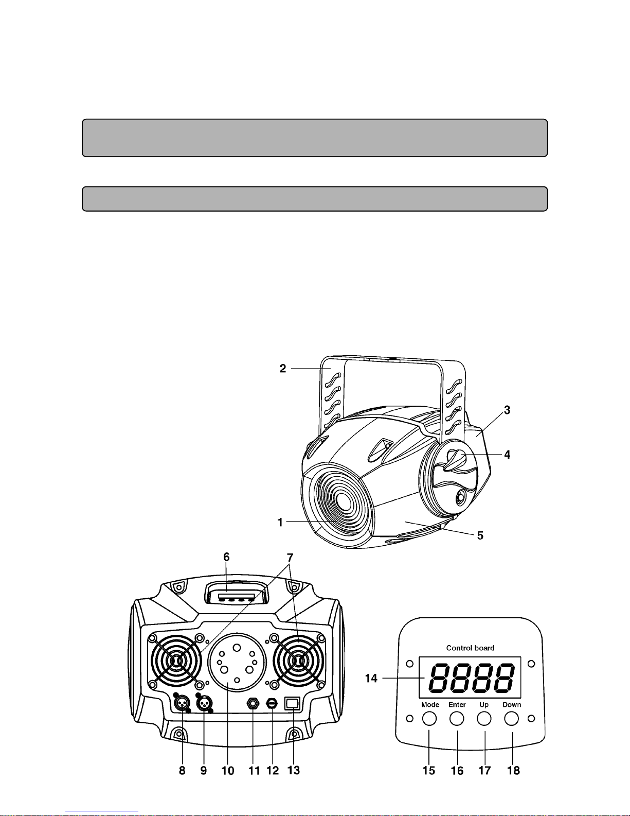
3. Description of the device
Rear side
Control panel
1 - Fresnel lens
2 - Mounting bracket
3 - Rear cover
4 - Adjusting screw
5 - Front cover
6 - Control board
7 - Fans
8 - DMX output
9 - DMX input
10 - Lamp cover
11 - Power cord
12 - Fuse holder
13 - Power switch
14 - Display
15 - Mode-button
16 - Enter-button
17 - Up-button
18 - Down-button
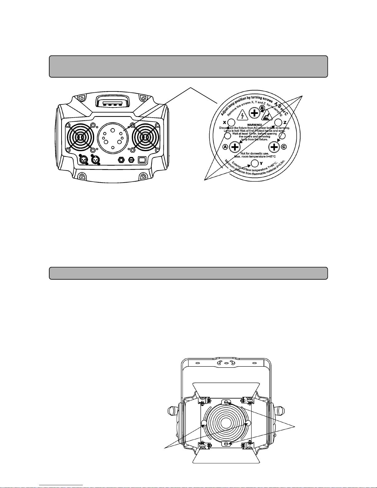
6
adjusting screws
fastening screws
4. Installation
4.1 Fitting/Exchanging the lamp
DANGER ! Install the lamp with the device switched off only.
Unplug from mains before !
To insert the lamp MSD 250W/2 open the small cover at the rear of the projector by loosening the 3 screws „X, Y, Z” on
the lamp cover.
Gently pull out the lamp socket assembly.
If changing the lamp, remove the old lamp from the socket. Insert the lamp to the socket.
Do not install a lamp with a higher wattage! A lamp like this generates temperatures the device is not designed for.
Damages caused by non-observance are not subject to warranty. Please follow the lamp manufacturer‘s notes!
Do not touch the glass-bulb bare hand during the installation! Make sure that the lamp is installed tightly into the lamp
holder system.
Reinsert the lamp assembly and tighten the 3 screws again.
Before striking the lamp, reset the „LAti/rSEt” and „LASt/rSEt” counters in the „InFO” menu on the control panel, by
pressing the [Up] and [Down] buttons in one time and then confirming with the [Enter] button.
Do not operate this fixture with opened housing-cover!
4.2 Lamp adjustment
The lamp holder is aligned at the factory. Due to differences between lamps, fine adjustment may improve light performance.
Strike the lamp, cancel all effects, open the shutter and set the dimmer intensity to maximum and focus the light on a flat
surface (wall) or use function „LAAd” in the Special functions of the control board.
Center the hot-spot (the brightest part of the beam) using the 3 adjustment screws „A, B, C”. Turn one screw at a time to
drag the hot-spot, diagonally across the projected image. If you cannot detect a hot- spot, adjust the lamp until the light is
even.
To reduce a hot-spot, pull the lamp in by turning all three screws „A, B, C” clockwise 1/4-turn at a time until the light is
evenly distributed.
If the light is brighter around the edge than it is in the center, or if light output is low, the lamp is too far back in the reflector.
„Push” the lamp out by turning the screws „A, B, C” counterclockwise 1/4-turn at a time the light is bright and evenly
distributed.
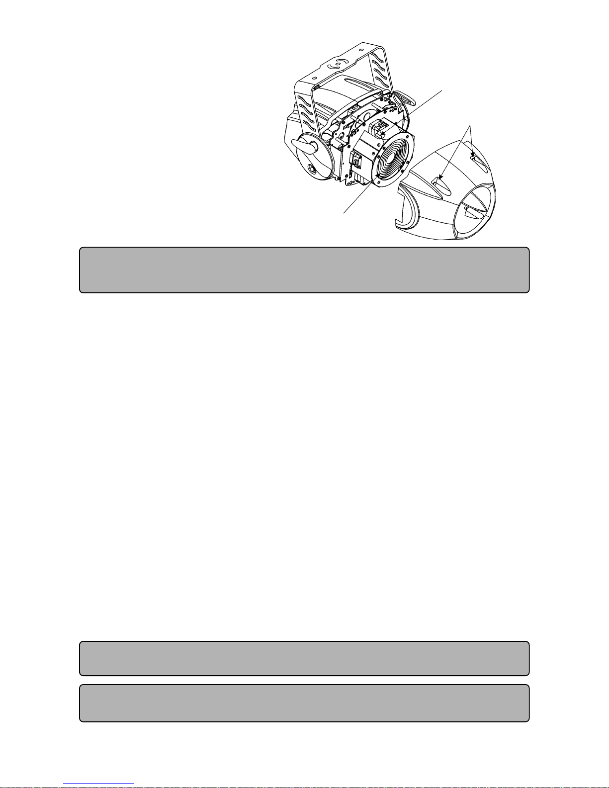
4.3 Installation of the barn-doors
You can install the barn-doors to better define the
iluminated surface.The barn-doors are fixed with
the 2 screws and may be turned in range 90°.
Note: The barn-doors are not standard part of
delivery, only on demand.
Lamp cover
3 fastening screws
screws „A, B, C”
7
4.4 Manually adjusment of the beam angle
The lens system can be configured in the range
between 8° and 22° beam angles.To set the
desired beam angle,remove the barn-doors (if they
are installed) by loosening the 2 fastening screws
and open the front cover by loosening the 4 quarter
turn fasteners, loose the 2 adjusting screws(with
knurled-head) on the fresnel lens unit and adjust
the required beam angle.Tighten the adjusting
screws again and fix back the front cover and barndoors.
4.5 Rigging
DANGER TO LIFE!
Please consider the respective national norms during the installation!
The installation must only be carried out by an authorized dealer!
The installation of the projector has to be built and constructed in a way that it can hold 10 times the weight for 1 hour
without any harming deformation.
The installation must always be secured with a secondary safety attachment, e.g. an appropriate catch net. This secondary
safety attachment must be constructed in a way that no part of the installation can fall down if the main attachment fails.
When rigging, derigging or servicing the fixture staying in the area below the installation place, on bridges, under high
working places and other endangered areas is forbidden.
The operator has to make sure that safety-relating and machine-technical installations are approved by an expert before
taking into operation for the first time and after changes before taking into operation another time.
The operator has to make sure that safety-relating and machine-technical installations are approved by an expert after
every four year in the course of an acceptance test.
The operator has to make sure that safety-relating and machine-technical installations are approved by a skilled person
once a year.
The projector should be installed outside areas where persons may walk by or be seated.
IMPORTANT! OVERHEAD RIGGING REQUIRES EXTENSIVE EXPERIENCE, including (but not limited to) calculating
working load limits, installation material being used, and periodic safety inspection of all installation material and the
projector. If you lack these qualifications, do not attempt the installation yourself, but instead use a professional structural
rigger. Improper installation can result in bodily injury and.or damage to property.
The projector has to be installed out of the reach of people.
If the projector shall be lowered from the ceiling or high joists, professional trussing systems have to be used. The projector
must never be fixed swinging freely in the room.
Caution: Projectors may cause severe injuries when crashing down! If you have doubts concerning the safety of a
possible installation, do NOT install the projector!
Before rigging make sure that the installation area can hold a minimum point load of 10 times the projector’s weight.
Danger of fire ! When installing the device, make sure there is no highly inflammable
material (decoration articles, etc.) in between a distance of min. 0,5 m.
CAUTION! Make sure that the device is fixed properly! Ensure that the structure
(truss) to which you are attaching the fixtures is secure.
The projector can be placed directly on the stage floor or rigged in any orientation on a truss without altering its operation
characteristics .
Adjusting screw
Quarter turn fasteners
Fresnel lens
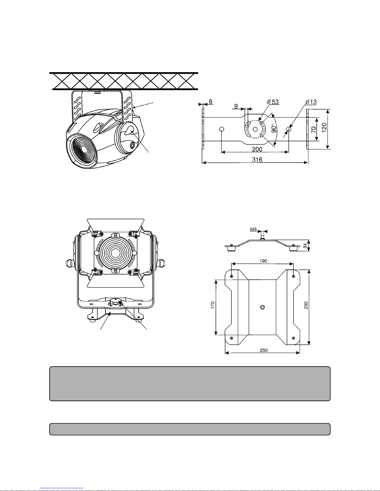
8
Overhead installation.
The mounting bracket provides 3 holes (a diameter of 13 mm) and 2 quarter-circle slots.
To adjust the inclination-angle,loosen the 2 adjusting screws.Turn the projector to the desired angle and retighten the
adjusting screws.
For overhead use, always install a safety rope that can hold at least 10 times the weight of the fixture. Pull the safety rope
through the mounting bracket and over the trussing system etc.
Floor installation.
The projector can stand directly on the floor by standing on the removable stand which is mounted with the nut M8 to the
projector's mounting bracket.
Note: The barn-doors are not standard part of delivery, only on demand.
DANGER TO LIFE!
Before taking into operation for the first time, the installation has to be approved by an expert!
When installing fixtures side-by-side, avoid illuminating one fixture with another!
4.6 Connection to the mains
Verify the power supply settings before applying power!
If you wish to change the power supply settings,see the chapter Appendix.
Connect the fixture to the mains with the enclosed power plug. If you need to install other power plug on the power cable,
follow the identification table below.
The earth has to be connected!
Mounting bracket
Adjusting screw
Removable stand:
Measurements are in milimetres
Mounting bracket (groundplan):
Measurements are in milimetres
Nut
Removable stand
9
The occupation of the connection-cables is as follows:
Cable (EU) Cable (US) Pin International
Brown Blac k Live L
Light blue White Neutral N
Yellow/Green Green Earth
Do not connect the projector to a dimmer system!
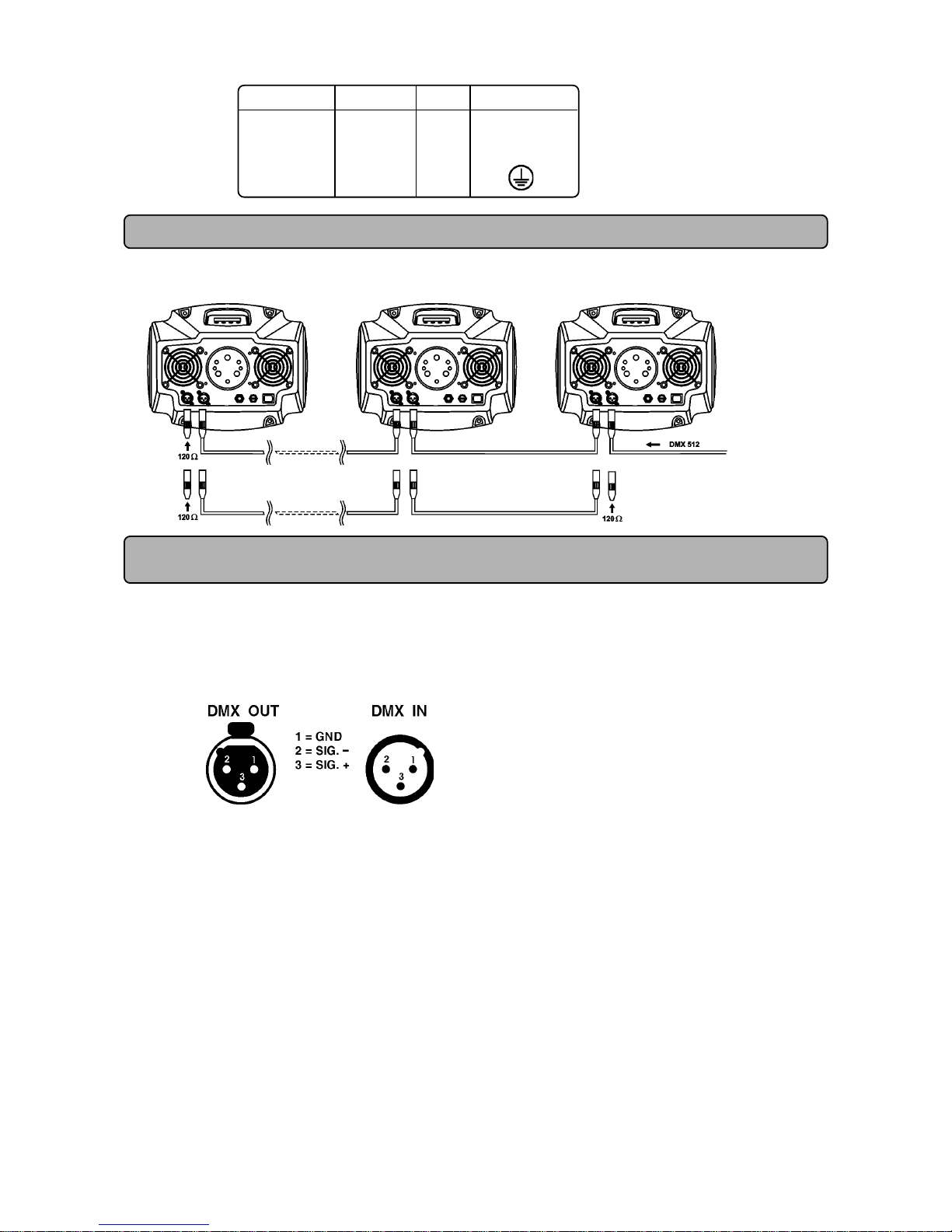
4.7 DMX- 512 connection, master/slave connection
The wires must not come into contact with each other, otherwise the fixtures will not
work at all, or will not work properly.
Only use a stereo shielded cable and 3-pin XLR-plugs and connectors in order to connect the controller with the fixture or
one fixture with another.
Occupation of the XLR-connection:
XLR mounting-socket: XLR mounting-plug:
Building a serial DMX-chain:
If you are using the standard controllers, you can connect the DMX-output of the controller directly with the DMX-input of
the first fixture in the DMX-chain. If you wish to connect DMX-controllers with other XLR-outputs, you need to use adaptercables.
Connect the DMX-output of the first fixture in the DMX-chain with the DMX-input of the next fixture. Always connect output
with the input of the next fixture until all fixtures are connected.
Caution: At the last fixture, the DMX-cable has to be terminated with a terminator. Solder a 120 Ohm resistor between
Signal (–) and Signal (+) into a 3-pin XLR-plug and plug it in the DMX-output of the last fixture.
Building a master/slave-chain:
Connect the DMX-output of the master fixture in the data-chain with the DMX-input of the first slave. Always connect output
with the input of the next slave until all slaves are connected (up to 9 fixtures).
Caution:It’s necessary to insert the XLR termination plug (with 120 Ohm) into the input of the master fixture and into the
output of the last slave fixture in the link in order to ensure proper transmission on the data link.
Master/slave operation
Controller operation
 Loading...