

Robe CitySkape 48 User Manual
Version 1.
8

CitySkape 48 (RGBW)
2
Table of contents
1. Safety instructions ...................................................................................................................................................... 3
2. Fixture exterior view ................................................................................................................................................... 5
3. Installation .................................................................................................................................................................. 5
3.1 Rigging the fixture ................................................................................................................................................. 5
3.2 Connection to the mains ...................................................................................................................................... 6
3.3 Changing the lens array ........................................................................................................................................ 6
3.4 Installation of the barn-doors ............................................................................................................................... 8
3.5 DMX 512 connection ............................................................................................................................................ 9
3.6 Master/slave connection ...................................................................................................................................... 9
3.7 Stand-alone operation ........................................................................................................................................ 10
4. CitySkape 48 (RGBCW) - DMX protocol .................................................................................................................... 11
5. Control menu map .................................................................................................................................................... 12
6. Fixture menu ............................................................................................................................................................. 14
6.1 Fixture Address ................................................................................................................................................... 15
6.2 Fixture information ............................................................................................................................................. 15
6.3 Personality .......................................................................................................................................................... 16
6.4 Manual mode ...................................................................................................................................................... 17
6. 5 Test sequences................................................................................................................................................... 17
6.6 Stand-alone setting ............................................................................................................................................. 17
6.7 Special functions ................................................................................................................................................. 19
7. RDM .......................................................................................................................................................................... 20
8. Wireless DMX operation ........................................................................................................................................... 21
9. Error and information messages .............................................................................................................................. 22
10. Technical specifications .......................................................................................................................................... 22
11. Cleaning and maintenance ..................................................................................................................................... 25
12. ChangeLog .............................................................................................................................................................. 25

CitySkape 48 (RGBW)
3
FOR YOUR OWN SAFETY, PLEASE READ THIS USER MANUAL CAREFULLY
BEFORE POWERING OR INSTALLING YOUR CitySkape 48 !
Save it for future reference.
This device has left our premises in absolutely perfect condition. In order to maintain this condition and to ensure a
safe operation, it is absolutely necessary for the user to follow the safety instructions and warning notes written in
this manual.
The manufacturer will not accept liability for any resulting damages caused by the non-observance of this manual
or any unauthorized modification to the device.
Please consider that damages caused by manual modifications to the device are not subject to warranty.
1. Safety instructions
DANGEROUS VOLTAGE CONSTITUTING A RISK OF ELECTRIC SHOCK IS PRESENT WITHIN THIS UNIT!
Make sure that the available voltage is not higher than stated on the rear panel of the fixture.
This fixture should be operated only from the type of power source indicated on the marking label. If you are not
sure of the type of power supplied, consult your authorized distributor or local power company.
Always disconnect the fixture from AC power before cleaning, removing or installing the fuses, or any part.
Do not overload wall outlets and extension cords as this can result in fire or electric shock.
Make sure that the power cord is never crimped or damaged by sharp edges. Check the fixture and the power cord
from time to time.
Do not install the unit near naked flames.
During the operation the housing becomes hot (up to 80°C)
Refer servicing to qualified service personnel.
This fixture falls under protection class I. Therefore this fixture has to be connected to a mains socket outlet with
a protective earthing connection.
Do not connect this fixture to a dimmer pack.
LED light emission. Risk of eye injury.
Do not look straight at the fixture´s LEDs during operation. The intense light beam may damage your eyes.
Keep compustible materials at least 20 cm away from the fixture.
If the fixture has been exposed to drastic temperature fluctuation (e.g. after transportation), do not switch it on
immediately. The arising condensation water might damage your device. Leave the device switched off until it has
reached room temperature.
Avoid brute force when installing or operating the fixture.

CitySkape 48 (RGBW)
4
The fixture was designed for both indoor and outdoor use. This fixture must not be used for underwater
installation.
When choosing the installation spot, please make sure that the fixture is not exposed to extreme heat or dust.
Avoid using the unit in locations subject to possible impacts.
The fixture body never must be covered with cloth or other materials.
Only operate the fixture after having checked that the housing is firmly closed and all screws are tightly fastened.
Make sure that the area below the installation place is blocked when rigging, derigging or servicing the fixture.
Do not block the front objective LEDs with any object when the fixture is under operation.
The fixture becomes very hot during operation. Allow the fixture to cool approximately 30 minutes prior to
manipulate with it.
Operate the fixture only after having familiarized with its functions. Do not permit operation by persons not
qualified for operating the fixture. Most damages are the result of unprofessional operation!
Do not attempt to dismantle or modify the unit.
Please consider that unauthorized modifications on the fixture are forbidden due to safety reasons!
Please use the original packaging if the fixture is to be transported.
If this device will be operated in any way different to the one described in this manual, the product may suffer
damages and the guarantee becomes void. Furthermore, any other operation may lead to dangers like shortcircuit, burns, electric shock etc.
CitySkape 48 (RGBW)
5
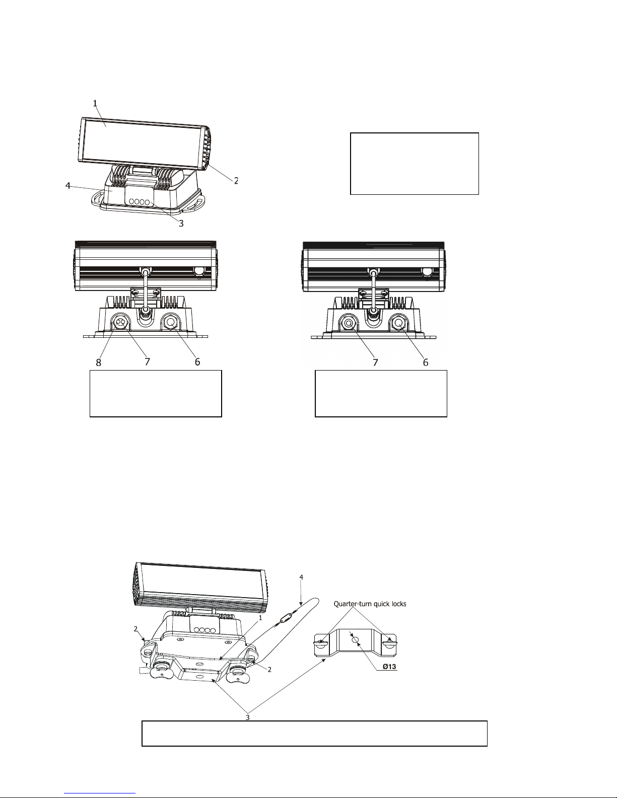
2. Fixture exterior view
Wireles DMX version
3. Installation
3.1 Rigging the fixture
The CitySkape 48 can be rigged in any orientation on a truss without altering its operation characteristics.
Installation on the truss allows the adapter for Omega holder (1) fastened to the fixture base with two bolts (2)
and the omega holder (3) for fastening a clamp.Pull through the safety rope (4) under the mounting holder and
For overhead use, always install a safety rope (4) that can hold at least 10 times the weight of the fixture. You must
only use safety rope with screw-on carbine. Pull the safety rope through the adapter for Omega holder (1) and over
the trussing system.
Ensure that the structure (truss) to which you are attaching
the fixture is secure
1. Lens array
2. Radiator
3. Control board
4. Base
6. Power cord
7. DMX in
8. DMX out
6. Power cord
7. Antenna
CitySkape 48 (RGBW)
6
Caution: Fixtures may cause severe injuries when crashing down! If you have doubts concerning the safety of a
possible installation, do not install the device and consult installation with an expert.
3.2 Connection to the mains
Fixtures must be installed by a qualified electrician in accordance with all national
and local electrical and construction codes and regulation.
Install a suitable plug on the power cord, note that the cores in the power cord are colored according to the
following table.
C
ore (Eu) C
ore (US) Connection
Plug Terminal Marking
Brown
Black
Live L
Light blue
White
Neutral
N
Yellow/Green Green Earth
This device falls under class one and must be grounded!
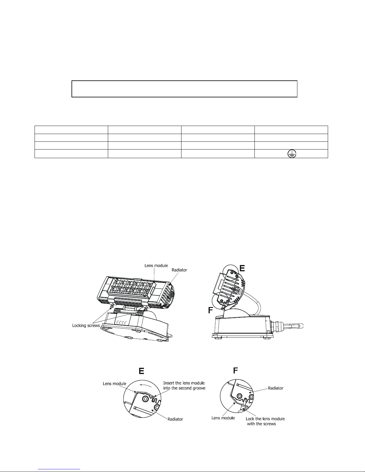
3.3 Changing the lens array
The standard beam angle of the fixture without lens-array is 12°.
If you need a wider beam angle than 12° , you have to install the eggcrate lens module 25° or the optional
eggcrate lens module 45°, 45°x15° or eggcrate top hat module (for placing frost foil under it).
How to install eggcrate lens module:
1. Disconnect the fixture from the mains.
2. Put the top edge of the eggcrate lens module into the second groove on the top side of the radiator ( detail
E) and the bottom edge into the second groove on the bottom side of the radiator ( detail F) and tighten
two locking screws M2 to secure the eggcrate lens module on the fixture´s radiator.
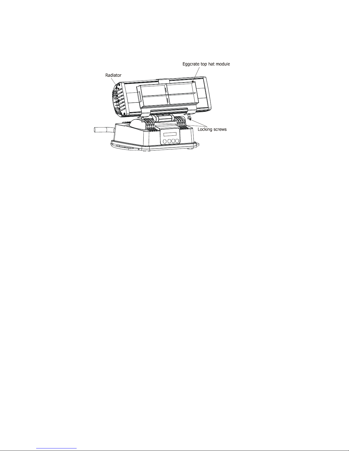
To install eggcrate lens module with frost foil.
1. Disconnect the fixture from the mains.
CitySkape 48 (RGBW)
7
2. Place the frost foil of dimensions of 61mm x 217 mm under eggcrate top hat lens module on the fixture´s
radiator .
3. Fasten the eggcrate top hat lens module on the radiator the same way as the eggcrate lens module.
The frost foil has to stand temperature of 80°C.
CitySkape 48 (RGBW)
8
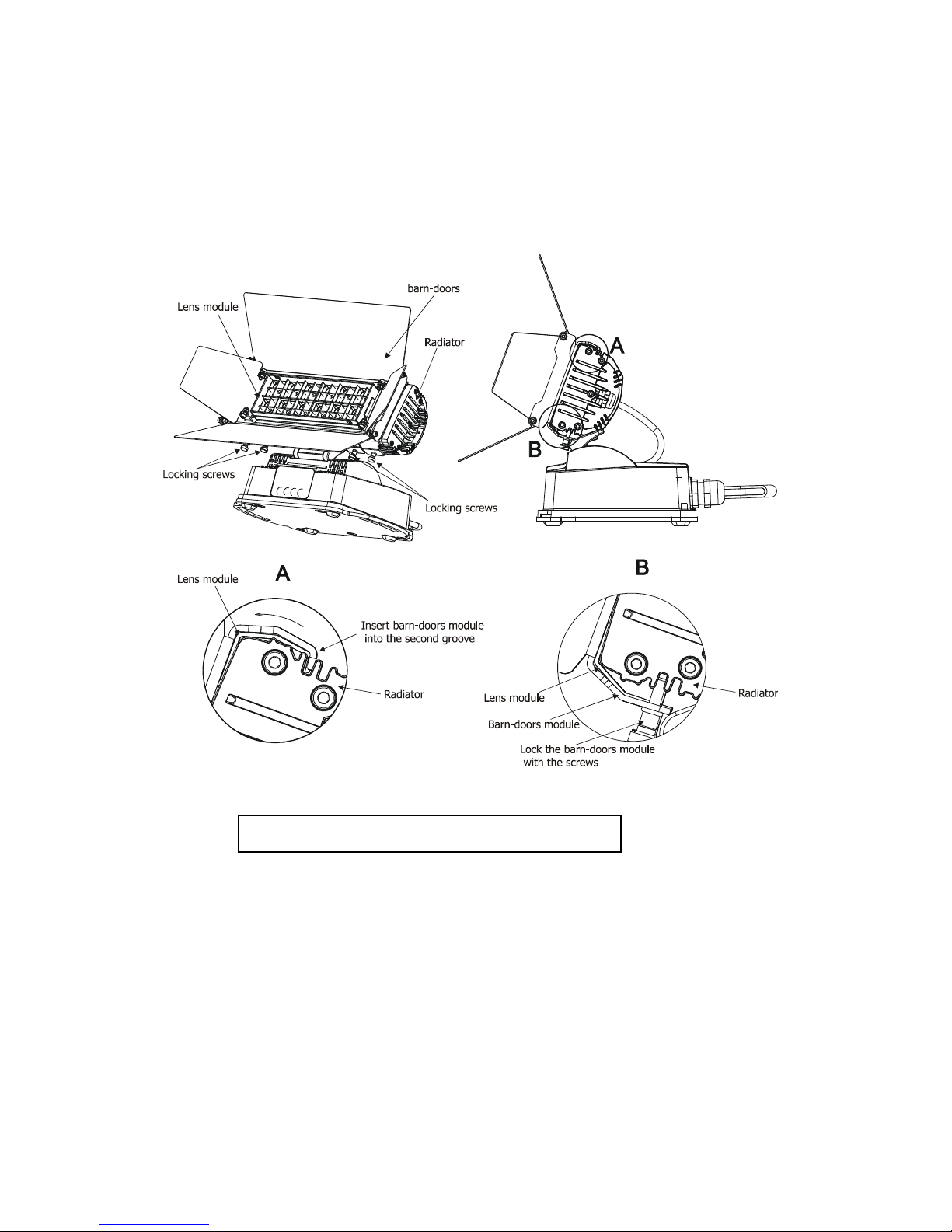
3.4 Installation of the barn-doors
You can install the barn-doors to better define illuminated surface. The barn-doors module is fastened in the
same way as the eggcrate lens module.
1. Disconnect the fixture from the mains.
2. Put the top edge of the barn-doors module into the second groove on the top side of the radiator ( detail
A) and the bottom edge into the second groove on the bottom side of the radiator and tighten four
locking screws M2 to secure this barn-doors module on the radiator.
Never close the barn-doors during fixture operation
 Loading...