

Robe Color Wasf 1200E, Color Wash I200E, 1200E Color Wash, Color Wash 1200E AT User Manual
Color
Wash
1200E
AT
USER MANUAL
Version: 5.0
ROBE® Lighting s.r.o. Czech Republic www.robe.cz


3
Table of contents
1. Unpacking 4
2. Safety instructions
4
3. Operating determinations
5
4. Description of the xture
6
5. Installation
8
5.1 Connection to the mains 8
5.2 Changing the power supply settings 8
5.3 Fitting the lamp 9
5.4 Lamp adjustment 9
5.5 Inserting/Exchanging colours 10
5.6 Changing the front lenses 10
5.7 Installing top hats 11
5.8 Rigging the xture 11
5.9 DMX-512 connection/connection between xtures 13
5.10 Ethernet connection 13
6. DMX Protocol 15
7. Controller mode 1
9
7.1 DMX addressing 19
7.2 Remotely controllable functions 19
8. Control menu map 20
9. Control menu 2
4
9.1 Fixture Address 24
9.2 Fixture informations 24
9.3 Personality 26
9.4 Lamp On/Off 28
9.5 Test sequences 28
9.6 Manual mode 28
9.7 Stand-alone setting 28
9.8 Reset functions 29
9.9 Special functions 29
10. Power down mode 30
11. RDM 3
1
12. Error and information messages
32
13. Technical specications 3
3
14. Maintenance and cleaning 3
7
Color
Wash
1200E
AT
4
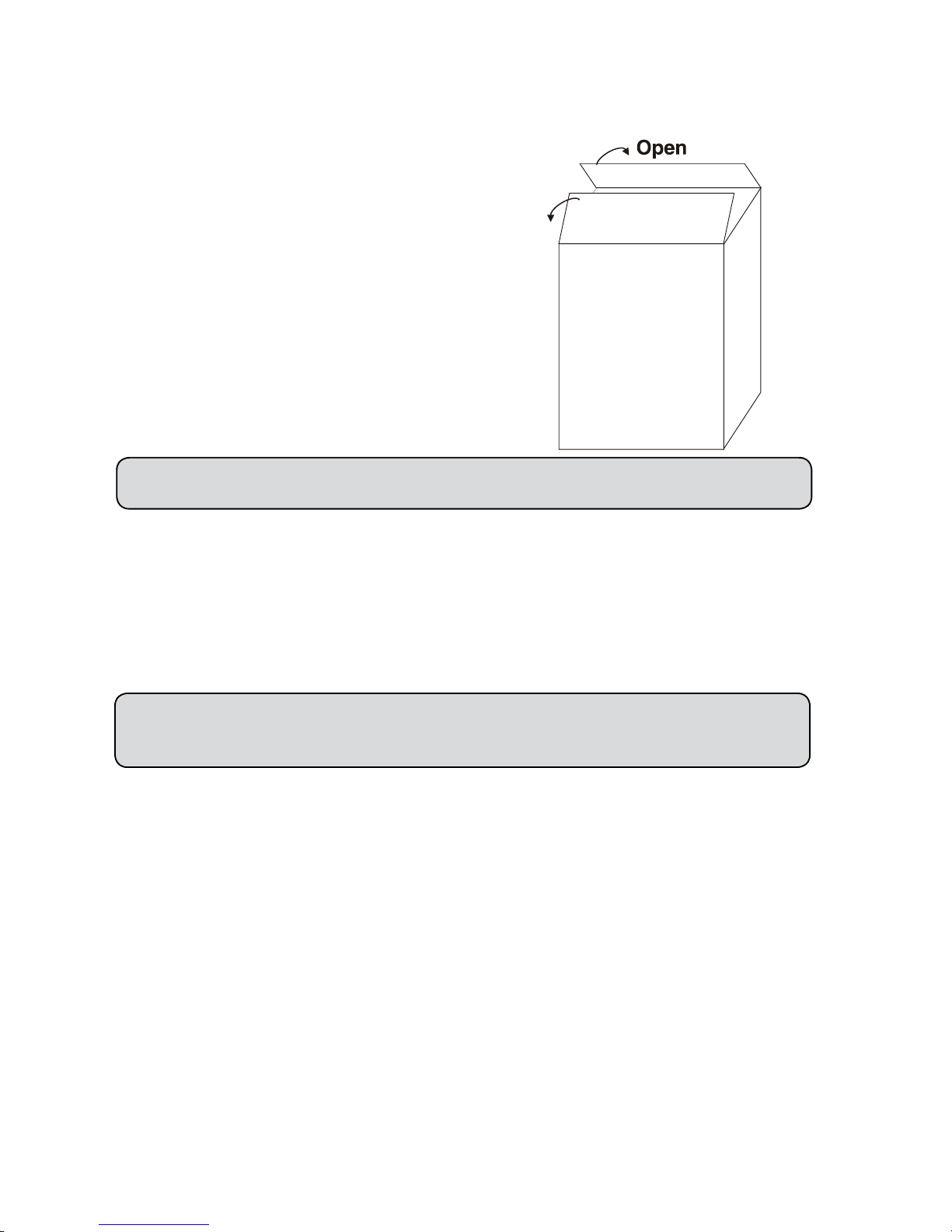
1. Unpacking
The ColorWash 1200E AT cardboard box included items:
- ColorWash 1200E AT
- Wide-angle lens (1piece)
- User manual (1piece)
- Small paper box with Mounting bracket Omega CL assembled (2 pieces)
The small paper box is situated in the top part of the cardboard box.
CAUTION! Keep this device away from rain and moisture!
Unplug mains lead before opening the housing!
FOR YOUR OWN SAFETY, PLEASE READ THIS USER MANUAL CAREFULLY
BEFORE YOU INITIAL START - UP!
2. Safety instructions
Every person involved with installation and maintenance of this device have to:
- be qualiled
- follow the instructions of this manual
CAUTION! Be careful with your operations.
With a high voltage you can suffer a dangerous electric shock
when touching the wires!
This device has left our premises in absolutely perfect condition. In order to maintain this condition and to ensure a safe operation, it is absolutely necessary for the user to follow the safety instructions and warning notes written in this manual.
Important:
The manufacturer will not accept liability for any resulting damages caused by the non-observance of this manual or any
unauthorized modication to the device.
Please consider that damages caused by manual modications to the device are not subject to warranty.
Never let the power-cord come into contact with other cables! Handle the power-cord and all connections with the mains
with particular caution!
Make sure that the available voltage is not higher than stated on the rear panel.
Always plug in the power plug least. Make sure that the power-switch is set to off-position before you connect the device
to the mains. The power-plug has to be accessable after installing the device.
Make sure that the power-cord is never crimped or damaged by sharp edges. Check the device and the power-cord from
time to time.
Always disconnect from the mains, when the device is not in use or before cleaning it. Only handle the power-cord by the
plug. Never pull out the plug by tugging the power-cord.
This device falls under protection class I. Therefore it is essential to connect the yellow/green conductor to earth.

5
The electric connection, repairs and servicing must be carried out by a qualied employee.
Do not connect this device to a dimmer pack.
Do not switch the xture on and off in short intervals as this would reduce the lamp’s life.
During the initial start-up some smoke or smell may arise. This is a normal process and does not necessarily mean that
the device is defective.
Do not touch the device’s housing bare hands during its operation (housing becomes hot)!
For replacement use lamps and fuses of same type and rating only.
CAUTION ! Avoid looking directly into the light source
EYEDAMAGES ! (meant especially for epileptics) !
3. Operating determinations
This device is a moving-head spot for creating decorative effects and was designed for indoor use only.
If the device has been exposed to drastic temperature uctuation (e.g. after transportation), do not switch it on immediately. The arising condensation water might damage your device. Leave the device switched off until it has reached room
temperature.
Never run the device without lamp!
Do not shake the device. Avoid brute force when installing or operating the device.
Never lift the xture by holding it at the projector-head, as the mechanics may be damaged. Always hold the xture at the
transport handles.
When choosing the installation-spot, please make sure that the device is not exposed to extreme heat, moisture or dust.
There should not be any cables lying around. You endanger your own and the safety of others!
The minimum distance between light-output and the illuminated surface must be more than 4 meters.
Make sure that the area below the installation place is blocked Always x the xture with an appropriate safety rope. Fix
the safety rope at the correct holes only.
Only operate the xture after having checked that the housing is rmly closed and all screws are tightly fastened.
The lamp must never be ignited if the objective-lens or any housing-cover is open, as discharge lamps may explose and
emit a high ultraviolet radiation, which may cause burns.
The maximum ambient temperature 40° C must never be exceeded. Otherwise, the lamp is switched off and the xture
is out of operation for 5
minutes.
CAUTION! The lens has to be replaced when it is obviously damaged,
so that its function is impaired, e. g. due to cracks or deep scratches!
Operate the device only after having familiarized with its functions. Do not permit operation by persons not qualied for
operating the device. Most damages are the result of unprofessional operation!
CAUTION! The lamp has to be replaced when it is damaged or deformed
due to the heat!
Please use the original packaging if the device is to be transported.
Please consider that unauthorized modications on the device are forbidden due to safety reasons!
If this device will be operated in any way different to the one described in this manual, the product may suffer damages
and the guarantee becomes void. Furthermore, any other operation may lead to dangers like short-circuit, burns, electric
shock, burns due to ultraviolet radiation, lamp explosion, crash etc.
CAUTION! The head and yoke must be unlocked before operation!
Check the pan/tilt locks!
6
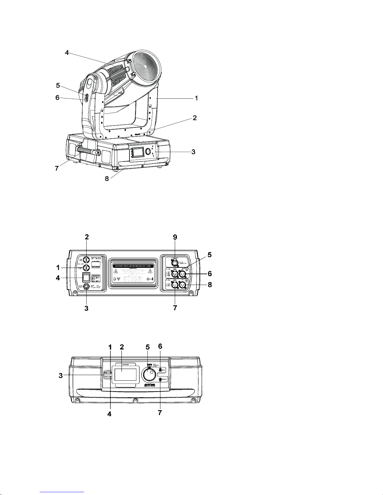
4. Description of the xture
The head can be locked for transportation- the tilt lock button (5) is pushed and the pan lock/unlock lever (2) is in lock
position. To unlock the head, press the tilt unlock button (6) and move the pan lock/unlock lever (2) to unlock position.
1 - Yoke
2 - Pan lock/unlock lever
3 - Front panel
4 - Moving head
5 - Tilt lock button (red)
6 - Tilt unlock button (green)
7 - Handle
8 - Base
Rear panel of the base
1 - Neutral fuse holder
2 - Live fuse holder
3 - Power cord
4 - Power switch
5 - 5-pin DMX output
6 - 5-pin DMX input
7 - 3-pin DMX output
8 - 3-pin DMX input
9 - Ethernet input
Front panel of the base
1 - Network indicator
2 - Display
3 - Infra-red sensor
4 - Data-transfer indicator
5 - RNS encoder wheel
6 - Escape button
7 - Enter button
7
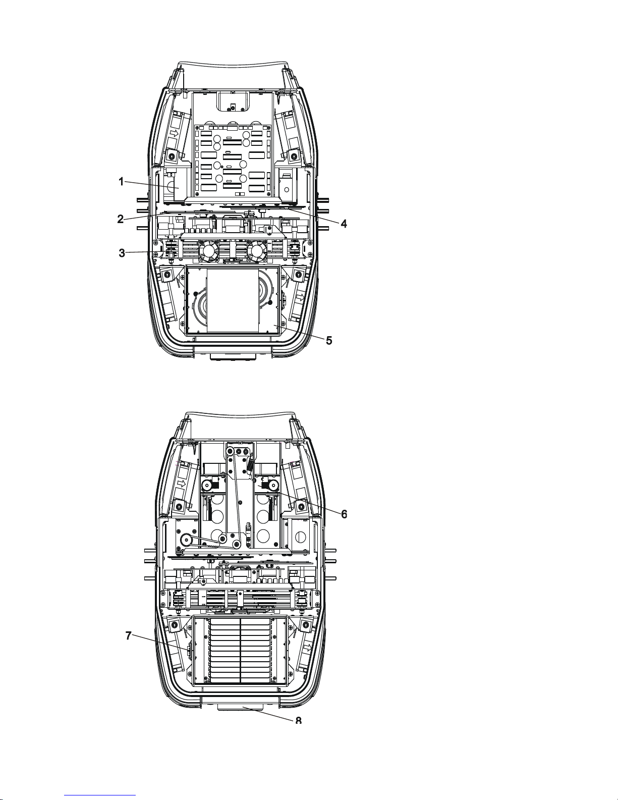
Head inside-top side
1 - Igniter
2 - Colour wheel 1
3 - CMY/conver.lter module
4 - Colour wheel 2
5 - Lamp chamber
Head inside-bottom side
6 - Inside Fresnel lens
7 - Termostat
8 - Lamp cover
8
5. Installation
Fixtures must be installed by a Qualied electrician in accordance with all
national and local electrical and construction codes and regulation.
5.1 Connection to the mains
Verify the power supply settings before applying power!
The factory settings are printed next to the power switch. If you wish to change the power supply settings, see the next
chapter.
Installl a 3-prong grounding-type plug on the power cable (US version). The earth has to be connected!
If you have any doubts about proper installation, consult a qualied electrician.
The occupation of the connection-cables is as follows:
Cable (EU) Cable (US) Pin International
Brown Black Live L
Liht blue White Neutral N
Yellow/Green Green Earth
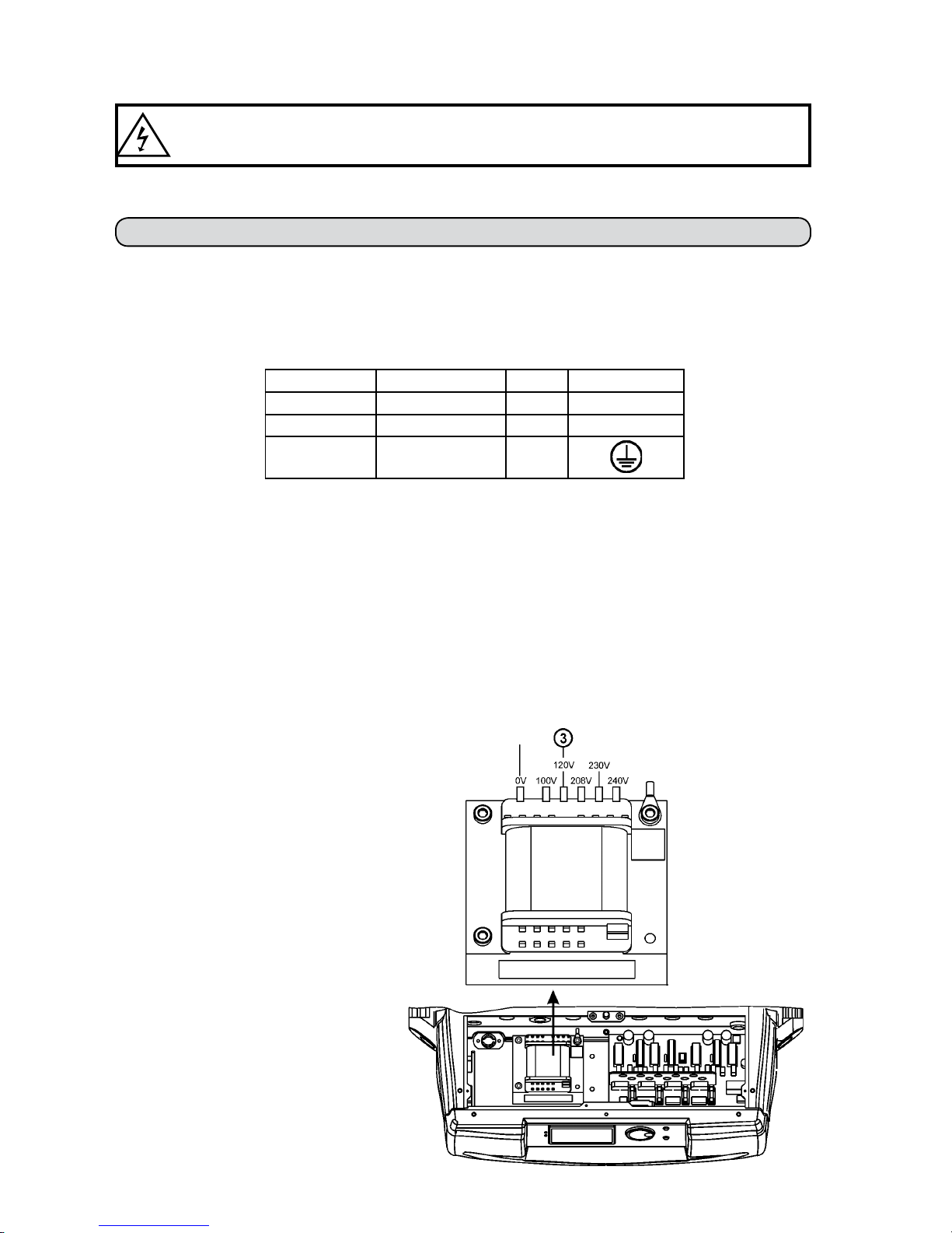
5.2 Changing the power supply settings
Electronic ballast
The operating range of the electronic ballast is 95 VAC-255 VAC. The transformer has to be set to the local AC voltage.
If you want to change the power supply settings, follow the instructions:
1. Disconnect the xture from AC power.
2. Remove the both top base covers by loosening
the 14 screws.
3. Move the wire (3) on the transformer connection block to the position according to the desired
voltage.
4. Close the base before applying AC power.
Transformer connection:
Power supply settins: 120V/60Hz
9
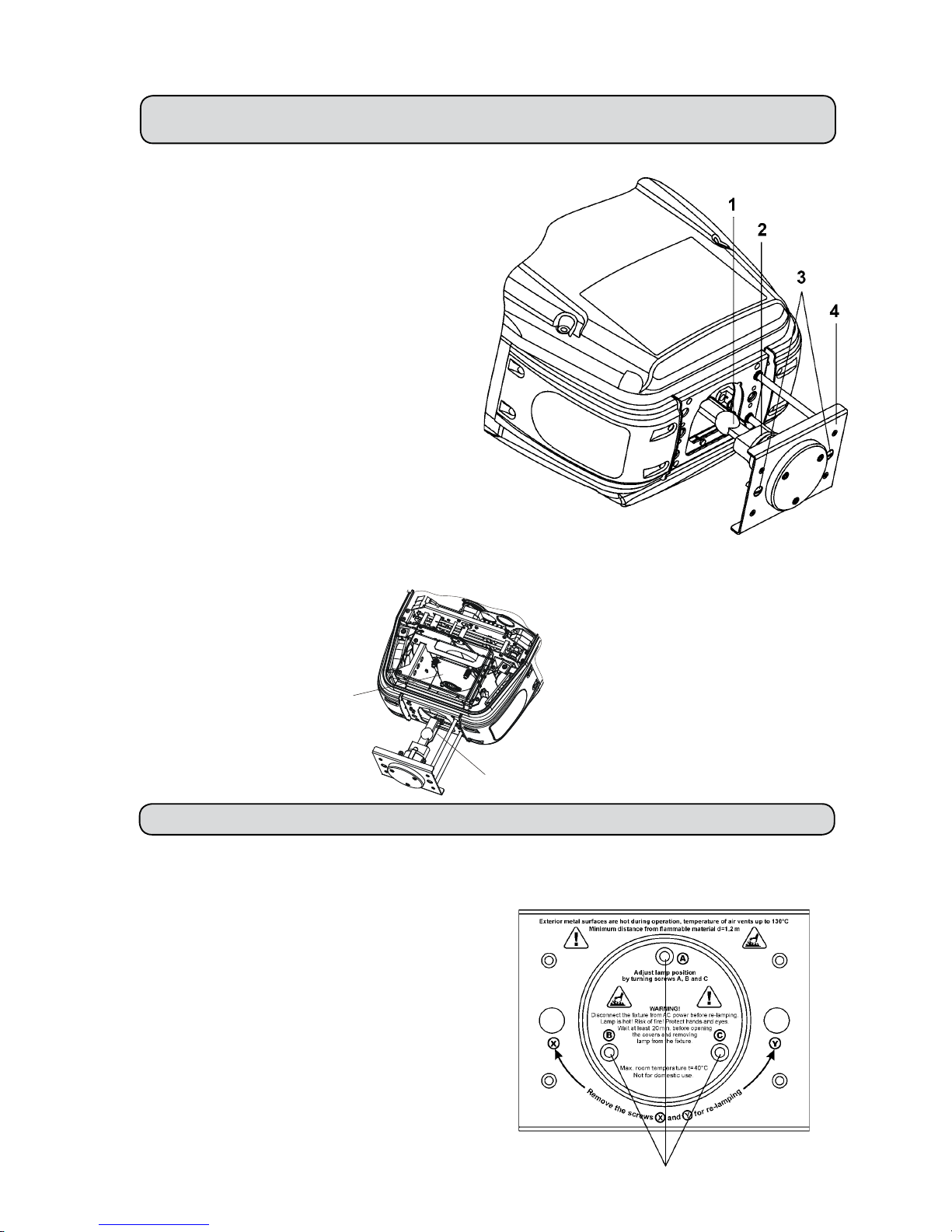
5.3 Fitting the lamp
DANGER ! Install the lamps with the device switched off only.
Unplug from mains before !
To insert the lamp (MSR 1200 SA):
1. Disconnect the xture from power and allow it to cool.
2. Loosen the 2 quarter-turn fasteners marked „X, Y,”
on the lamp cover at the back of the head.
3. Gently pull the lamp cover with lamp holder out of
the head.
4. Holding the lamp by its ceramic base, carefully pull
the lamp straight out of the lamp socket.
5. Holding the new lamp by its ceramics base, gently
insert the lamp to the lamp socket. Make sure that the
lamp is installed tightly into the lamp socket.
Do not install a lamp with a higher wattage! A lamp like
this generates temperatures the device is not designed
for. Damages caused by non-observance are not sub-
ject to warranty. Please follow the lamp manufacturer‘s
notes! Do not touch the glass bulb bare hand during
the installation!
6. Reinsert the lamp cover with the lamp holder and
installed lamp back to the head and tighten
the 2 quarter-turn
fasteners again.
Warning:if you feel any resistance during this action
, check the lamp electrode position and use „A,B,C“
screws to adjust right lamp position.Never put the lamp
in by force otherwise you will bend the lamp
electrode by the adge of the reector! (See picture
bellow)
7. Align the new lamp.
8. Reset „Lamp On Time” and „Lamp Strikes” counters
in „Fixture information” menu.
Do not operate this xture with opened housing-cover!
5.4 Lamp adjustment
The lamp holder is aligned at the factory.
Due to differences between lamps, ne adjustment may improve light performance:
1. Switch on the xture and after reset turn on the lamp.
2. Cancel all effects, open the shutter and focus the light on a
at surface (wall) using either DMX controller or function
“Lamp adjustment” in “Special functions menu”.
3. Center the hot-spot (the brightest part of the beam) using the
3 adjustment screws „A, B, C”. Turn one screw at a time to
drag the hot-spot, diagonally across the projected image. If
you cannot detect a hot -spot, adjust the lamp until the light
is even.
To reduce a hot-spot, pull the lamp in by turning all three
screws „A, B, C” clockwise 1/4-turn at a time until the light is
evenly distributed.
If the light is brighter around the edge than it is in the center,
or if light output is low, the lamp is too far back in the reector.
„Push” the lamp out by turning the screws „A, B, C” counterclockwise 1/4-turn at a time until the light is bright and evenly
distributed.
1 - Lamp
2 - Lamp holder
3 - 2 quarter-turn fasteners
4 - Lamp cover
3 adjustment scews „A, B, C”
Reector
Lamp electrode-check its position before insertion
to the reector
10
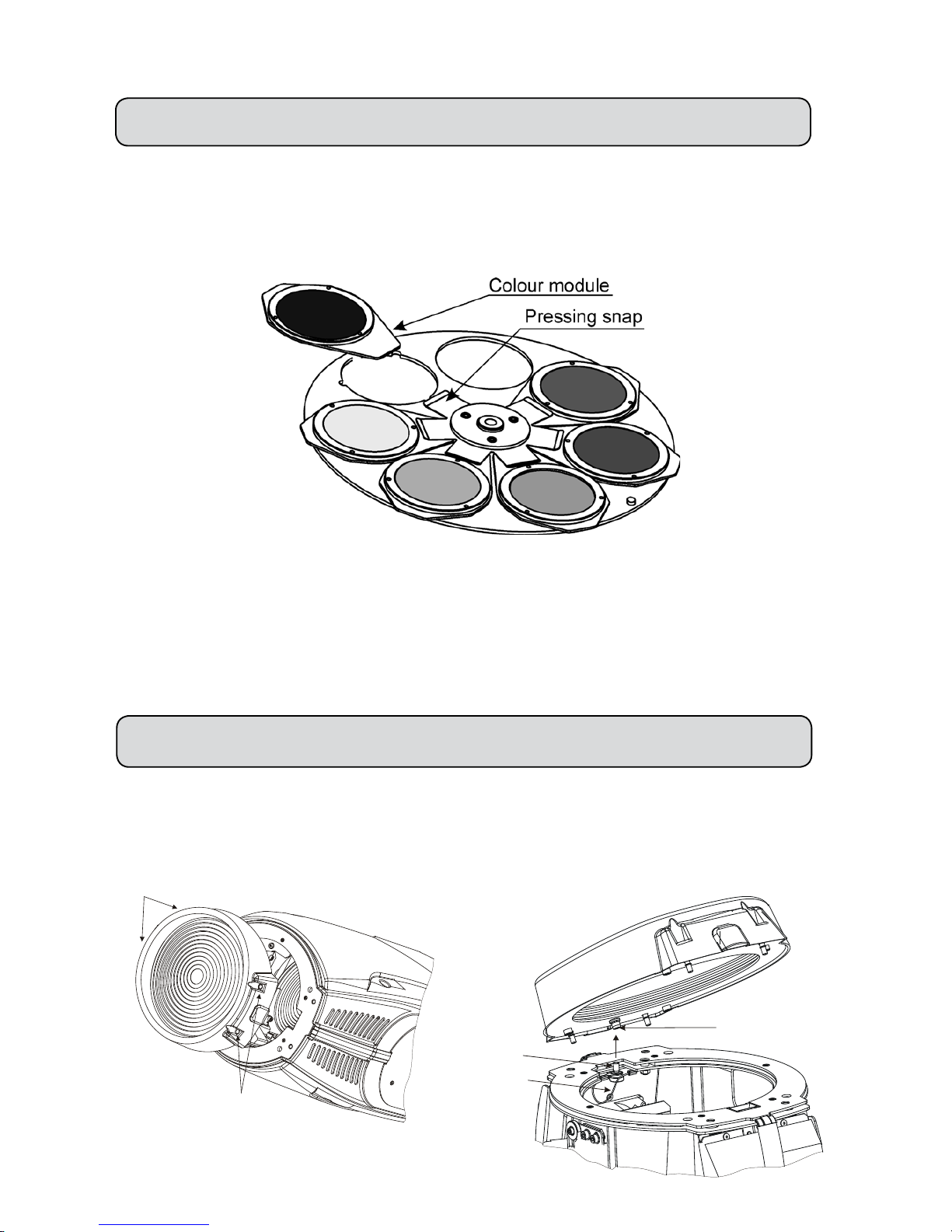
5.5 Inserting/Exchanging colours
DANGER!
Install the colours with the device switched off only.
Unplug from mains before!
Turn off the lamp and allow it to cool for at least 10 minutes. Disconnect the xture from power.
Open the bottom cover of the moving head by loosening the 4 quarter-turn fasteners on the top cover and follow the
instructions below:
1. Gently bend out the colour module to release it from the xative holes and eject it from the pressing snap.
2. Put the new colour module back under the pressing
snap and push it to the 3 xative notches.
5.6 Changing the front lenses
The ColorWash 1200E AT is supplied with the 2 types of the front lenses (Fresnel lens,wide-angle lens) and the Fresnel
lens is installed as standard.
Switch the device off before changing the lens.Be careful.Front lens is very
heavy!
If you want to change the front lens,follow the instructions:
1.Remove the front lens using a athead screwdriver to unlock the four quarter-turn screws.
2.Unscrew the safety cabel from the lens
3.Screw up the safety cable to the desired lens.
4.Place this lens and x it by locking the four quarter-turn screws.
Quarter-turn screws
Quarter-turn
screws
Nut
Bolt
Safety cable
11
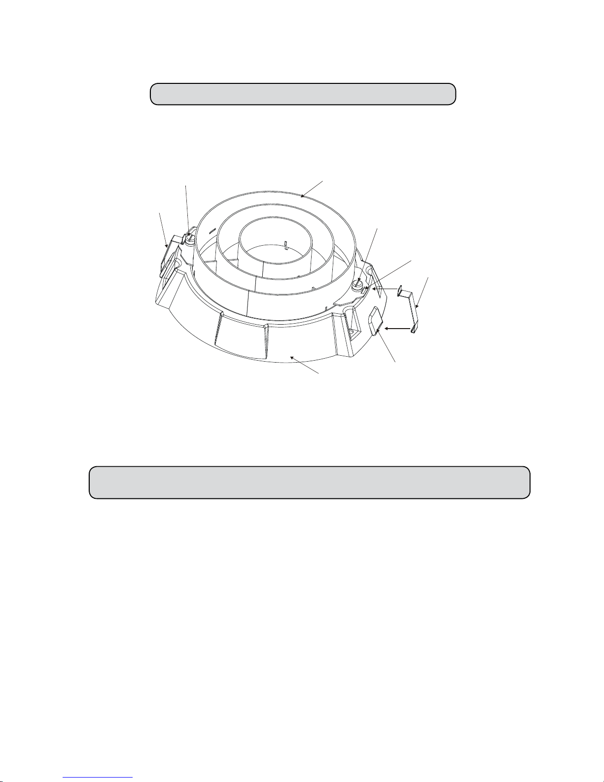
5.7 Installing top hats
The ColorWash 1200E AT can be tted with various types of the top hats-see chapter "Technical specications".If you
wish to install a top hat (optional),follow the instructions:
Switch the device off before installing the top hat!
Installing the top hat on the front lens-holder of the xture:
1.Loosen 4 lens holder quarter-turn screws and hook both securing springs to the plastic projections in the front lens-holder.
Tighten the 4 lens holder quarter-turn screws again.
2.Put desired top hat onto a front lens-holder and fasten it by two fastening screws.
3.Snap both springs to the slots in the top hat.
5.8 Rigging the xture
DANGER TO LIFE!
Please consider the respective national norms during the installation!
The installation of the xture has to be built and constructed in a way that it can hold 10 times the weight for 1 hour without
any harming deformation.
The installation must always be secured with a secondary safety attachment, e.g. an appropriate catch net. This secondary
safety attachment must be constructed in a way that no part of the installation can fall down if the main attachment fails.
When rigging, derigging or servicing the xture staying in the area below the installation place, on bridges, under high
working places and other endangered areas is forbidden.
The operator has to make sure that safety-relating and machine-technical installations are approved by an expert before
taking into operation for the rst time and after changes before taking into operation another time.
The operator has to make sure that safety-relating and machine-technical installations are approved by an expert after
every four year in the course of an acceptance test.
The operator has to make sure that safety-relating and machine-technical installations are approved by a skilled person
once a year.
Allow the xture to cool for ten minutes before handling.
The projector should be installed outside areas where persons may walk by or be seated.
IMPORTANT! OVERHEAD RIGGING REQUIRES EXTENSIVE EXPERIENCE, including calculating working load limits,
installation material being used, and periodic safety inspection of all installation material and the projector. If you lack these
Slot
Securing spring
Plastic projection
Securing spring
Top hat
Fastening screw
Fastening screw
Lens-holder
12
qualications, do not attempt the installation yourself, but instead use a professional structural rigger. Improper installation
can result in bodily injury and or damage to property.
The xture has to be installed out of the reach of people.
If the xture shall be lowered from the ceiling or high joists, professional trussing systems have to be used. The xture
must never be xed swinging freely in the room.
Caution: Fixtures may cause severe injuries when crashing down! If you have doubts concerning the safety of a possible
installation, do not install the xture!
Before rigging make sure that the installation area can hold a minimum point load of 10 times the xture’s weight.
Danger of re!
When installing the device, make sure there is no highly inamma-
ble material (decoration articles, etc.) in between a distance of min. 1.2 m.
CAUTION! Use 2 appropriate clamps to rig the xture on the truss.
Follow the instructions mentioned at the bottom of the base.
Make sure that the device is xed properly!
Ensure that the structure (truss)
to which you are attaching the xtures is secure.
The moving-head can be placed directly on the stage oor or rigged in any orientation on a truss without altering its operation characteristics .
The Omega holders can be placed in 4 positions on the bottom of the base. Use the clamps (not included in delivery)
with screws M12.
For overhead use, always install a safety-rope that can hold at least 10 times the weight of the xture. You must only use
safety ropes with screw-on carabines. Pull the safety rope through the two apertures on the bottom of the base and over
the trussing system etc. Insert the end in the carabine and tighten the xation screw.
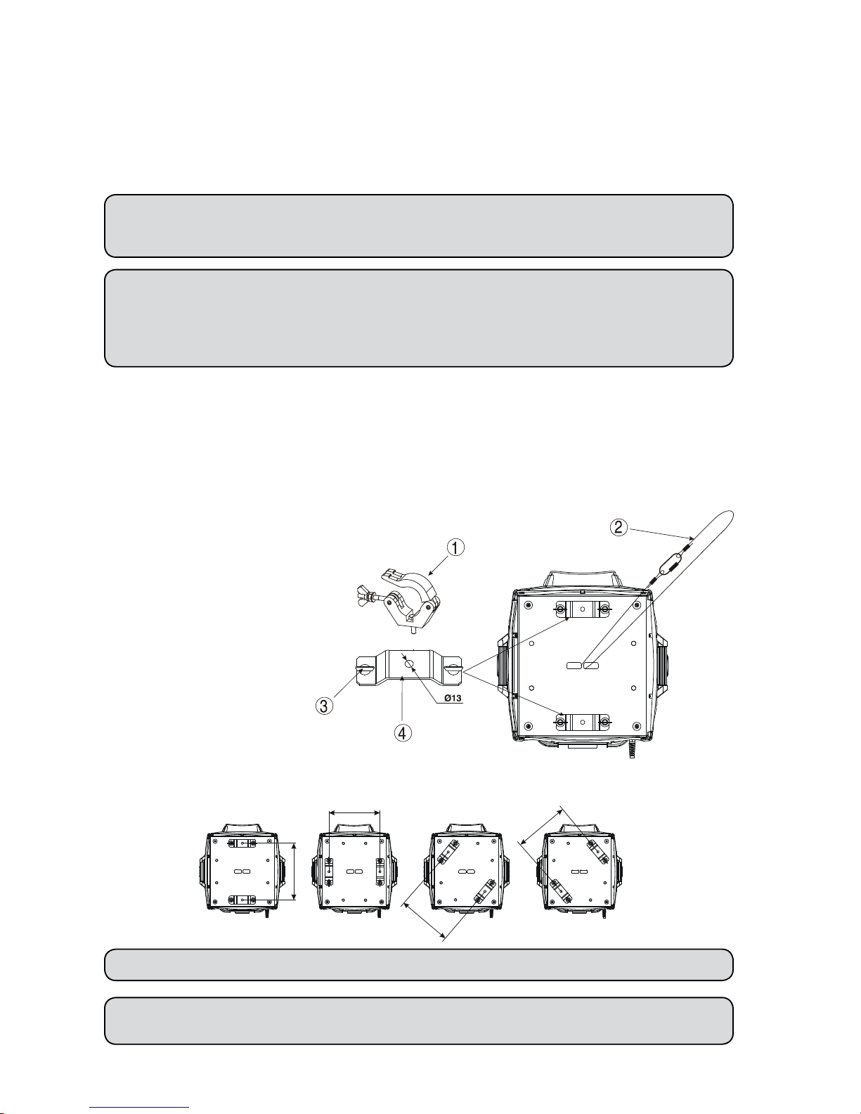
Fixation via the omega holders
1. Bolt each clamp (1) to the omega
holder (4) with M12 bolt and lock nut
through the hole in the holder.
2. Fasten the omega holders on the
bottom of the base by inserting both
quick-l ock fastener s (3) into the
holes of the base and tighten fully
clockwise.
3
. Fasten the safety-rope (2) through the
two apertures on the bottom of the
base and over the trussing system.
1 - Clamp
2 - Safety-rope
3 - Quick-lock fastener
4 - Omega holder
Possible omega holder 4 positions (dimensions in mm):
When installing xtures side-by-side, avoid illuminating one xture with another!
DANGER TO LIFE! Before taking into operation for the rst time,
the installation has to be approved by an expert!
 Loading...