

Page 1
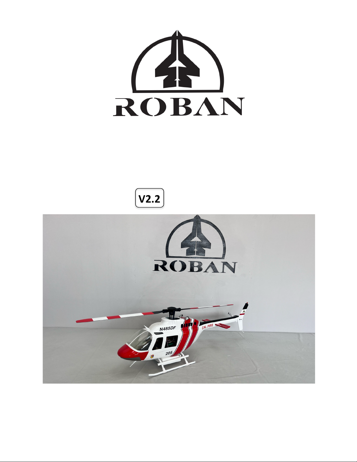
Roban B-206 470
User Manual
V2.2 2025.01
© 2024 Roban All Rights Reserved. 1
Page 2

Item No.: HSM-470-R-JR
This document is copyrighted by ROBAN with all rights reserved. Unless otherwise authorized by ROBAN, you are not eligible to use
or allow others to use the document or any part of the document by reproducing, transferring or selling the document. Users should
only refer to this document and the content thereof as instructions to operate ROBAN UAV. The document should not be used for
other purposes. All instructions, warranties and other collateral documents are subject to change at the sole discretion of Roban Model
Limited. For up-to-date product literature, visit robanmodel.com and click on the support or tab for this product.
Copyright © 2024 by Roban Model Limited
Searching for Keywords
Search for keywords such as “battery” and “install” to find a topic. If you are using Adobe Acrobat Reader to read this document, press
Ctrl+F on Windows or Command+F on Mac to begin a search.
Navigating to a Topic
View a complete list of topics in the table of contents. Click on a topic to navigate to that section.
Printing this Document
This document supports high resolution printing.
Page 3
Using this manual
Legend
Important Hints and Tips Reference
Read Before First Flight
Read the following documents before using the ROBAN MD-500E 470:
1. Safety Guidelines
2. Quick Start Guide
3. User Manual
It is recommended to watch all tutorial videos on the official ROBAN website and read safety guidelines before using for the first time.
Prepare for your first flight by reviewing the quick start guide and refer to this user manual for more information.
Video Tutorials
Go to the address below or scan the QR code to watch the ROBAN MD-500E 470 tutorial videos, links are in the description, which
demonstrate how to use the 470 series safely.
470 RTF B-206 | Roban Model
© 2024 Roban All Rights Reserved. 3
Page 4

Contents
Using this manual .......................................................................................................................................................... 3!
Product profile .............................................................................................................................................................. 6!
Introduction ............................................................................................................................................................... 6!
Technical data ........................................................................................................................................................... 6!
Product Components ................................................................................................................................................. 7!
TOOLS, ADHESIVES, additional components ............................................................................................................. 7!
Understanding the radio control ............................................................................................................................... 8!
Safety Section ................................................................................................................................................................ 9!
General Safety Guidelines ......................................................................................................................................... 9!
Pre-flight Safety Checks ............................................................................................................................................. 9!
In-Flight Safety ........................................................................................................................................................ 10!
Post-Flight Safety .................................................................................................................................................... 10!
Additional Safety Precautions and Warnings .......................................................................................................... 10!
Lithium Polymer Battery Operating Instructions ..................................................................................................... 11!
Quick Start Guide ........................................................................................................................................................ 12!
Preparation .................................................................................................................................................................. 15!
Removing the items from the packaging ................................................................................................................ 15!
Storing the product ................................................................................................................................................. 15!
Installation of rotor blades ...................................................................................................................................... 16!
Installation of the battery ....................................................................................................................................... 17!
Center of gravity ................................................................................................................................................. 18!
Operation/Use ............................................................................................................................................................. 19!
Charging the batteries ............................................................................................................................................ 19!
Charger information ................................................................................................................................................ 19!
Switching the equipment on and off ....................................................................................................................... 20!
Turn on the Transmitter .......................................................................................................................................... 20!
Turn on Helicopter .............................................................................................................................................. 21!
Wait for the Controller initialization ................................................................................................................... 21!
Getting ready to fly in GPS mode ............................................................................................................................ 22!
Arm the helicopter .................................................................................................................................................. 23!
Start the motors ...................................................................................................................................................... 23!
Fly the Helicopter .................................................................................................................................................... 24!
Flight maneuvers (MODE 2) .................................................................................................................................... 25!
B-206 Water Tank Operation .................................................................................................................................. 26!
GPS near Ground Interference ................................................................................................................................ 27!
Keep Track of Flight Time ........................................................................................................................................ 27!
Landing the Helicopter ............................................................................................................................................ 28!
Page 5

Flight mode chart .................................................................................................................................................... 28!
Controller Flight Mode Description ......................................................................................................................... 29!
Use cases for each mode ......................................................................................................................................... 29!
GPS Mode ................................................................................................................................................................ 29!
ANGLE Mode ........................................................................................................................................................... 30!
Manual Mode .......................................................................................................................................................... 30!
Return to Home (RTH) Mode ................................................................................................................................... 30!
Loss of Signal: ..................................................................................................................................................... 31!
Low Voltage Return: ........................................................................................................................................... 31!
On Command Return: ......................................................................................................................................... 31!
Electronic components and documentation ............................................................................................................... 32!
Controller ports and description .............................................................................................................................. 32!
Controller Port Wiring and Specifications ............................................................................................................... 33!
Controller status light description ........................................................................................................................... 33!
GPS Sensor .............................................................................................................................................................. 34!
Dual channel ESC ..................................................................................................................................................... 35!
Swash Servos designation and wiring ..................................................................................................................... 36!
LED Light system ..................................................................................................................................................... 37!
Troubleshooting, Support and Warranty .................................................................................................................... 38!
Adjusting the controller ........................................................................................................................................... 38!
Helicopter blade tracking and maintenance ........................................................................................................... 38!
Technical support .................................................................................................................................................... 38!
Warranty and Replacement Process ....................................................................................................................... 38!
Product Compliance and Conformity .......................................................................................................................... 39!
Product Compliance ................................................................................................................................................ 39!
Software Licensing and Attribution: ........................................................................................................................ 40!
Appendix A. Mechanical Spare Parts ........................................................................................................................... 41!
Appendix C. Spare parts explosion drawings .............................................................................................................. 48!
Appendix C. Explosion drawings .................................................................................................................................. 52!
© 2024 Roban All Rights Reserved. 5
Page 6

Product profile
Parameter
Unit
Size, weight
850*210*270mm, 1.87kg TOW
Main and tail rotor diameter
840mm (380*40), 130 mm (4045)
Motors
2820 1300KV, 2205 2450KV
ESC
1*40A + 1*20A dual ESC unit
Battery
14.8V 4S 5200mAh LIPO (required, included)
Radio Control
FlySky S-i6s, 10ch S-BUS transmitter + RX (included)
Charger
Included
This section introduces the ROBAN MD-500E 470 and lists the components of the aircraft and remote controller.
Introduction
ROBAN MD-500E 470 is a remote controlled scale helicopter capable of hovering and flying indoors and outdoors and can
automatically Return to Home. The helicopter features an electronic control system that makes flying as easy and intuitive as operating
a camera drone. The product is intended for individuals of 14 years of above of age, with a basic understanding of mechanical systems
and a cautionary approach to operating remote controlled devices.
Technical data
Page 7
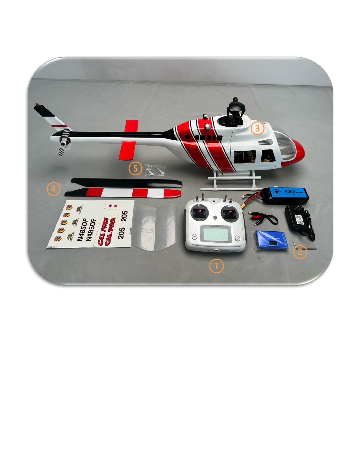
Product Components
1. Radio Control
2. Charger and power cord
3. Helicopter fuselage
4. Main rotor Blades
5. Scale parts and fasteners
TOOLS, ADHESIVES, additional components
• Hexagonal allen key 2.5mm
• Screwdriver PH1.5
• Epoxy fast curing adhesive
• Transparent tape (for temporarily holding parts in place while glue is setting)
• 4pcs AA-Type batteries for transmitter
© 2024 Roban All Rights Reserved. 7
Page 8
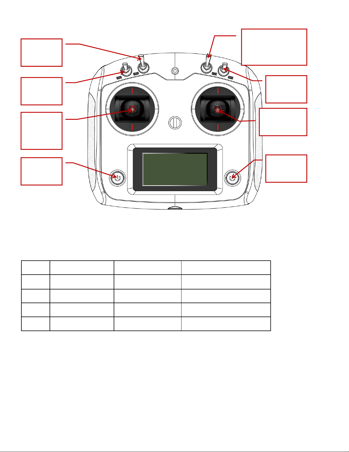
Understanding the radio control
Name
Function
Name
Function
Switch A
Throttle on-off
Stick left
Up-down/turn left-right
Switch B
Accessory control
Stick right
Nick fwd-aft/Bank left-right
Switch C
Stabilization mode
Power left
On-off (always press both)
Switch D
Auto RTH
Power right
On-off (always press both)
Switch B:
Accessory
e.g. Gear
Switch C:
Flight Stabilization Mode
GPS
Angle
Manual
Power:
on-off
Power:
on-off
Switch A:
Motor Cut
Motor Run
Switch D:
Auto Return to
home
Stick (Mode 2):
Up, Down
Yaw Nose Left,
Right
Stick (Mode 2):
Pitch Fwd, Aft
Roll Left, Right
Fig. 2 Radio control front side
Page 9

Safety Section
Please note that this product is not intended to be used as a toy. The rotor blade tips can achieve speeds exceeding 500 km/h during flight, which can cause significant
damage to property, or serious injury to animals and people, up to and including death. Additionally, in the event of a malfunction, an uncontrolled descent could
occur, causing the product to fall uncontrollably. As such, it is imperative that the product be flown only in unpopulated, open areas.
Exercise extreme caution and thoroughly read the entire instruction manual before operating this product. Familiarize yourself with all features to ensure proper
and safe usage. Improper use can result in damage to the product, personal property, and may lead to serious injury or death. Basic mechanical skills are required
to operate this product, and you should always use caution and common sense.
Do not use incompatible components or make modifications beyond the instructions provided by Roban Model Limited. The manual contains critical information
regarding safety, operation, and maintenance, and it is essential to follow all instructions and warnings carefully to avoid injury, property damage, or worse.
Children should not use this product without direct adult supervision. Always ensure the helicopter is operated in a safe, responsible manner.
General Safety Guidelines
• Always maintain a safe distance around your helicopter in all directions during operation to avoid injuries or collisions. The rotor blades can reach high
speeds, posing serious risks.
• Operate in open spaces. Fly only in clear, open areas free of obstacles like buildings, power lines, trees, or people. Avoid flying near water, crowds, or traffic.
• Always keep the helicopter in sight. Maintain visual line-of-sight with the helicopter during flight. Avoid flying higher than 120 meters to remain within safe
operational boundaries and comply with local regulations.
• Never allow children to operate the helicopter without direct adult supervision. The product is not a toy and improper use can lead to serious injury or
damage.
• Avoid using the product near flammable materials. The battery and other electrical components can generate heat during operation.
• Do not modify the product in any way. Any unauthorized modifications could damage the product, invalidate the warranty, or result in dangerous
malfunction.
• Check weather conditions before flight. Avoid flying in rainy, windy, or foggy conditions, as these can interfere with flight control.
Pre-flight Safety Checks
Before every flight, perform the following safety checks to ensure proper operation and avoid accidents:
1. Inspect the Helicopter:
o Check that all screws, fasteners, and parts are securely in place.
o Ensure that the rotor blades are properly installed and secured.
2. Battery Condition:
3. Transmitter and Receiver:
4. Environment Check:
o Check for any visible damage or wear, especially on the fuselage and blades.
o Make sure the battery is fully charged and properly connected.
o Inspect the battery for any signs of damage, swelling, or overheating.
o Ensure that the transmitter has fresh batteries.
o Test all controls to ensure they respond correctly before attempting takeoff.
o Choose an open area with no obstructions or bystanders.
o Make sure weather conditions are calm and suitable for flying.
© 2024 Roban All Rights Reserved. 9
Page 10

In-Flight Safety
• Keep control of the helicopter at all times. Even when using assisted flight modes (such as GPS or Return to Home), keep your hands on the transmitter and
remain aware of the helicopter’s position.
• Maintain a safe altitude. Fly at an altitude that ensures safe separation from obstacles, especially during takeoff and landing. Be ready to manually adjust
the throttle if the helicopter suddenly loses altitude.
• Do not attempt aggressive maneuvers if you are not experienced. Stunt maneuvers, fast descents, or high-speed turns can destabilize the helicopter and
result in crashes.
• Avoid flying near animals or people. The helicopter’s high-speed rotors can cause severe injury. Always ensure the flight area is free from bystanders, pets,
or vehicles.
• Be prepared to land quickly in case of low battery warnings, loss of signal, or any unusual behavior from the helicopter.
Post-Flight Safety
• Turn off the motors as soon as the helicopter lands.
• Disconnect the battery before handling or performing any post-flight maintenance. Let the battery and helicopter components cool down before touching
or recharging them.
• Inspect for damage after each flight, especially after any hard landings or crashes. Check the rotor blades, frame, and electrical components for wear and
tear.
Additional Safety Precautions and Warnings
• Always keep a safe distance in all directions around your model to avoid collisions or injury. This model is controlled by a radio signal subject to
interference from many sources outside your control. Interference can cause momentary and extended loss of control.
• Always operate your model in open spaces away from full-size vehicles, traffic and people.
• Always carefully follow the directions and warnings for this and any optional support equipment (chargers, rechargeable battery packs, etc.).
• Always keep all chemicals, small parts and anything electrical out of the reach of children.
• Always avoid water exposure to all equipment not specifically designed and protected for this purpose. Moisture causes damage to electronics.
• Never place any portion of the model in your mouth as it could cause serious injury or even death.
• Always operate your model with fully charged transmitter batteries.
• Always keep aircraft in sight and under control.
• Always move the throttle fully down at rotor strike.
• Always use fully charged batteries.
• Always keep transmitter powered on while aircraft is powered.
• Always remove batteries before disassembly.
• Always keep moving parts clean.
• Always keep parts dry.
• Always let parts cool after use before touching.
• Always remove batteries after use.
• Never operate aircraft with damaged wiring.
• Never touch moving parts.
Page 11

Lithium Polymer Battery Operating Instructions
• YOU MUST READ ALL OF THE SAFETY INSTRUCTIONS AND WARNINGS BEFORE USE.
• Lithium Polymer (LiPo) batteries are volatile. Failure to read and follow the proper use and charging instructions below may result in fire, personal injury and/or damage to property.
• Motion RC / Roban Model does not assume any liability for failures to comply with these warnings, instructions, and safety guidelines.
• By purchasing this battery, the buyer assumes all risks associated with LiPo batteries. If you do not agree with these conditions, return the battery immediately before use.
SAFETY
• Only use a charger which is specifically designed for Lithium Polymer batteries.
• Never charge batteries unattended. You should constantly observe the charging process and immediately react to any potential problems that may occur.
• Batteries should be placed on a heat-resistant, non-flammable surface during charging.
• If you see the battery balloon or swell, stop charging immediately. Disconnect the battery and observe it in a safe place away from flammable materials inside a fireproof container for approximately 60 minutes. Continuing
to charge a battery that has begun to swell will result in fire and/or explosion. Never use or attempt to charge a battery that is swollen or ballooned.
• Certain Li-Po chargers may not work properly and may cause them to charge Li-Po batteries incorrectly or at an improper rate. It is your responsibility solely to assure the charger you purchased works properly. Always
monitor the charging process to assure batteries are being charged properly. Failure to do so may result in fire and/or explosion.
• Never open the battery covering, modify the battery connector, or short the wire leads of a battery. These actions can result in fire and/or explosion.
• Never puncture a battery or store it near sharp or pointed objects or surfaces. A punctured battery can result in fire
• If the battery is involved in a crash, put the battery in a safe fireproof area and observe for 60 minutes. It is highly recommended that batteries involved in a crash are removed from service. Internal damage not obvious
to the naked eye can result in fire.
BEFORE CHARGING
• Please read the charger instruction manual completely before charging your battery.
• Always check the voltage of batteries before charging to ensure they are at or above the minimum safe starting voltage. Never charge a battery pack which is below 3.7V per cell. For example, a 3 cell (3S) pack should not
be charged if it is below 11.1V. If the starting voltage is below recommended levels, then the batteries have been over discharged or have experienced a failure and should NOT be charged.
• Ensure each cell's voltage is within 0.1V of the others. Do not attempt to charge a battery with imbalanced cells.
• Always inspect the battery for any type of damage before charging. Look for any damaged leads, connectors, broken shrink wrap, swelling of cells, or other irregularities. Do not use the battery if you find any of the above
issues with your pack.
• Ensure you are using battery charge leads which are compatible with the connector on your battery.
• Check the polarity of the battery cable and charger lead carefully before the connection to avoid any short circuit.
• Always verify the charger is in good condition before use. A poor-quality charger can be dangerous. It is solely your responsibility to assure that the charger you use works properly. Failure to do so may result in a fire
and/or explosion.
• If your battery develops a distinct smell, often sweet or acrid, this can be a sign of internal damage. Discontinue use immediately and do not charge.
CHARGING
• Always charge batteries in an isolated area on a heat-resistant, non-flammable surface (such as concrete) outside of buildings and away from flammable materials, liquids and surfaces.
• Never charge batteries that are hot to the touch. The battery temperature should be the same as the ambient temperature before charging.
• Always select LiPo balance charging. This requires the use of the white JST/XH balance connector for all charging.
• Make sure to set the charger to the correct number of cells and voltage shown on the battery label.
• The charger should never be set to charge batteries at a rate greater than 1C (One (1) times the capacity of batteries in amp hours).
• Never charge LiPo batteries over 4.2V per cell. Charging a LiPo battery for an extended period will result in fire and/or explosion.
• Never charge multiple battery packs together in series. Charge each pack individually.
• Use suitable and good quality chargers with proper certification marks (UL Listed, etc.). Never use inexpensive and low quality chargers.
• Always disconnect the battery connector from the charger’s charging cable first. Do not remove the charger’s charging cable from the charger first because its exposed leads could contact each other, causing a potentially
dangerous short in the battery attached to it.
STORAGE
• Store at room temperature between 40 and 80 °F (4 to 27 °C). Storage at higher temperatures may result in failure and fire.
• Always store batteries between 3.75V and 3.9V per cell. Storage at higher or lower voltages may result in damage.
• Never store loose batteries together, the terminals may contact one another causing a short circuit.
• Always store LiPo batteries in a safe fireproof container away from flammable materials.
• Never store batteries in extreme temperatures or direct sunlight.
DISCHARGING
• Never discharge LiPo batteries at rates higher than specified C rating on the label.
• Never allow the temperature of batteries to exceed 140 °F (60 °C) during discharge. Adequate cooling for batteries is required, especially when discharging at or near maximum rates.
• Never discharge battery to a level below 3V per cell under load or 3.7V per cell resting.
• Do not run the battery down to the ESC cutoff voltage. Operating an RC product to the point that its motor stops working will result in irreparable damage to the battery. The ESC cutoff voltage is for the safety of the
aircraft and bystanders. When the battery is discharged this far, it should be removed from service.
• Never leave battery unattended during the discharging process.
LIMITED WARRANTY
• Motion RC LLC / Roban Model Limited reserves the right to change or modify this warranty without notice and disclaims all other warranties, express or implied. This warranty is limited to the original purchaser and is not
transferable. Third party transactions are not covered by this warranty. Product warranty is limited to original defects in material and workmanship. The warranty does not cover collateral damage. Due to the nature and
use of this product there is no term warranty. Misuse, abuse, incorrect charging, failure to comply with the above warnings and guidelines, and other inappropriate use of this product are not covered under the warranty.
© 2024 Roban All Rights Reserved. 11
Page 12

Quick Start Guide
Follow these steps to get your Roban MD-500E 470 ready for flight quickly. For detailed instructions and safety information, refer to
the full manual.
1. Unboxing
Remove all packaging materials.
Ensure all items are present:
• Helicopter fuselage
• Main rotor blades
• Charger
• Battery
• Transmitter (Radio Control)
• Scale parts (optional)
• Tools and accessories
Place the helicopter on a clean, flat surface to avoid damage.
2. Charging the Battery
Step 1: Connect the charger to a power outlet (100-240V).
Step 2: Attach the battery to the charger using the balance port (white plug).
Step 3: Wait until the charger displays "FUL" before disconnecting.
Note: Charging may take up to 5 hours depending on the battery's charge level.
3. Battery Installation
Step 1: Remove the canopy by gently lifting it off.
Step 2: Place the LiPo battery on the designated tray and secure it with the Velcro strap.
Step 3: Ensure the battery is centered to maintain proper balance.
Step 4: Connect the battery plug to the power socket inside the fuselage.
Tip: Ensure that the battery is fully charged before installation (see step 4 for charging instructions).
4. Transmitter Setup
Step 1: Insert 4 AA batteries into the transmitter’s battery compartment.
Step 2: Turn on the transmitter by pressing and holding both power buttons for 2 seconds.
Step 3: Check the display to ensure the transmitter is working properly.
Note: Ensure all switches are in the "up" position before turning on the transmitter.
5. Attaching Rotor Blades
Step 1: Carefully align the main rotor blades with the preinstalled screws and lock nuts.
Step 2: Insert and tighten the screws, ensuring the blades can move freely but aren’t too loose.
Page 13

6. Powering Up the Helicopter
Step 1: With the transmitter powered on, install the canopy and place the helicopter on a flat surface.
Step 2: Connect the helicopter's power by plugging in the battery connector.
Step 3: Wait for the controller to initialize (it will flash green when ready).
7. Flight Mode Setup
Set the transmitter to GPS Mode for stable and safe flight. This is recommended for beginners.
Make sure all switches on the transmitter are in the proper positions before starting the motors.
8. Arm the Helicopter
Step 1: Arm the helicopter by moving the left control stick (Mode 2) to the lower middle position and holding for 3 seconds.
Step 2: When the controller light turns solid green, the helicopter is ready for flight.
9. Takeoff
Step 1: Slowly push the throttle (left stick) upwards to lift the helicopter off the ground.
Step 2: Maintain an altitude of at least 1 meter for stable flight.
10. Landing
Step 1: To land, gradually reduce the throttle to bring the helicopter down smoothly.
Step 2: After landing, turn off the motors by moving the throttle stick fully down and switching off the motor switch.
11. After Flight
Step 1: Disconnect the battery from the helicopter.
Step 2: Turn off the transmitter by pressing and holding both power buttons.
Step 3: Allow the motors and battery to cool down before handling.
Key Tips:
For Beginners: Always fly in GPS Mode for easier control.
Safe Flight: Avoid flying in windy conditions and always stay within line of sight.
Charging Safety: Never leave the battery unattended while charging.
© 2024 Roban All Rights Reserved. 13
Page 14

For more details on advanced features, flight modes, or troubleshooting, refer to the full manual.
Page 15

Preparation
Removing the items from the packaging
To unpack the product safely:
• Remove all packaging tape that ties down the fuselage inside the transport carton.
• Remove the fuselage from the carton. With the landing gear not extended, it is easy to scratch the painted underside. Place
on a clean, soft cloth.
• Begin unpacking the mechanics, rotor blades and the accessories. Check if all parts are included.
Storing the product
The paint used on the fuselage is made from an environmentally friendly polyurethane resin but is not UV-resistant. It is important to
store the product in a location that protects it from prolonged exposure to sunlight, as the colors may fade and the clearcoat may
yellow.
The epoxy resins and PVC windows have a low glass transition temperature and can become soft and permanently deform at
temperatures as low as 50°C/120°F. Avoid storing the product in a car on hot days or in garages or sheds where temperatures may
exceed this level.
The batteries used in the RC product must not exceed temperatures of 60°C/140°F to prevent damage. Like all electronic products
that bring different metals into contact, exposure to humidity can cause the surfaces to oxidize and potentially harm the product.
To store the product safely:
• Don’t store above 50°C/120°F
• Don’t store lithium batteries above 60°C/140°F or below 0°C/32°F
• Charge lithium batteries only with appropriate chargers
• Use a BAT-SAFE for additional safety on batteries
• Don’t store with exposure to sunlight.
• Don’t store under humid conditions of 60%RH or above over prolonged periods.
© 2024 Roban All Rights Reserved. 15
Page 16
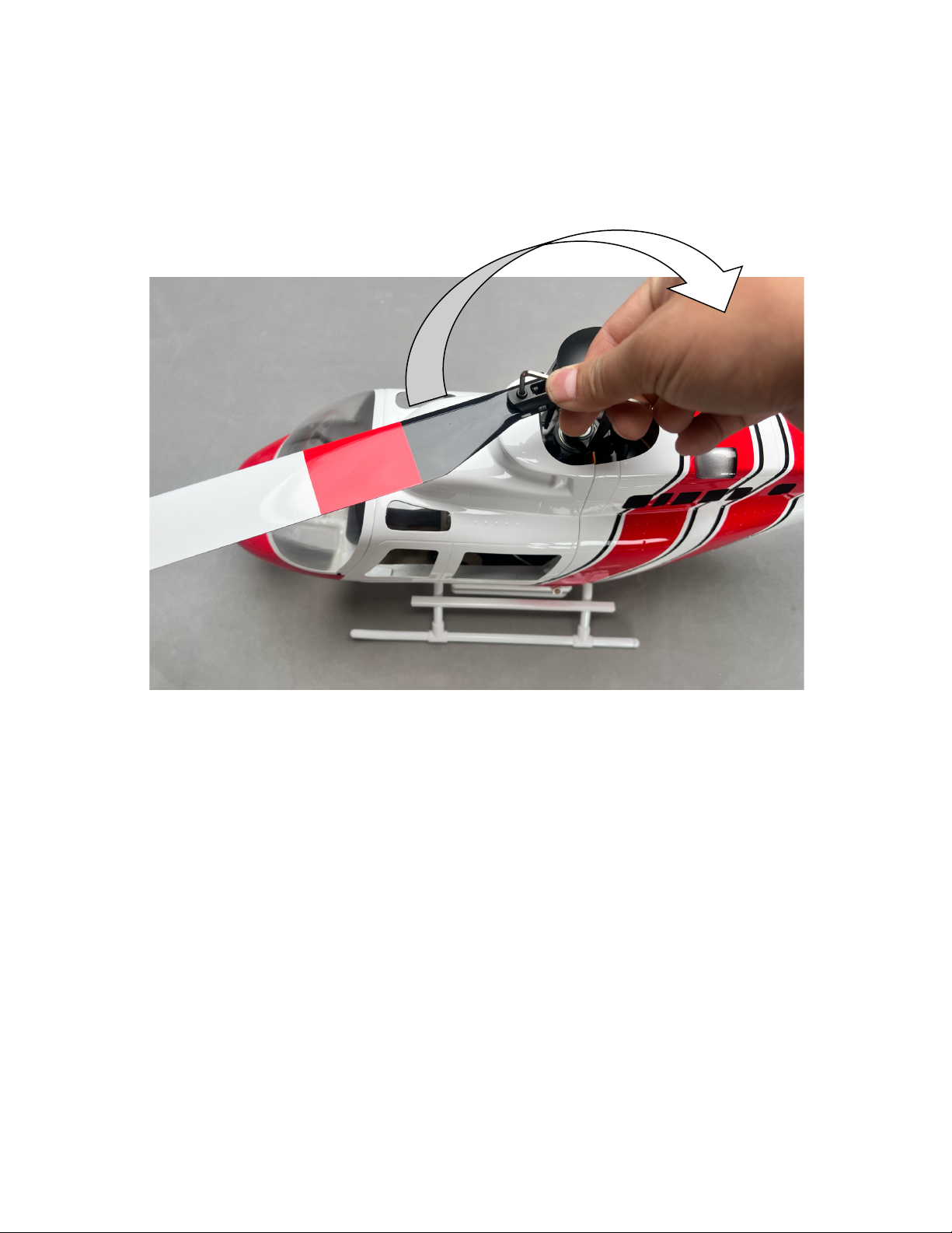
Installation of rotor blades
Properly install the rotor blades using the preinstalled screws and lock nuts, following the illustration for the correct rotational
direction. Remove the screws, insert the blades and install the blades. Avoid overtightening the screws, as the blades should not be
too loose in the grips, but also be easily movable by hand inside the grips.
If the blades are overtightened in the grips, this can cause vibrations when the helicopter spools up.
Page 17
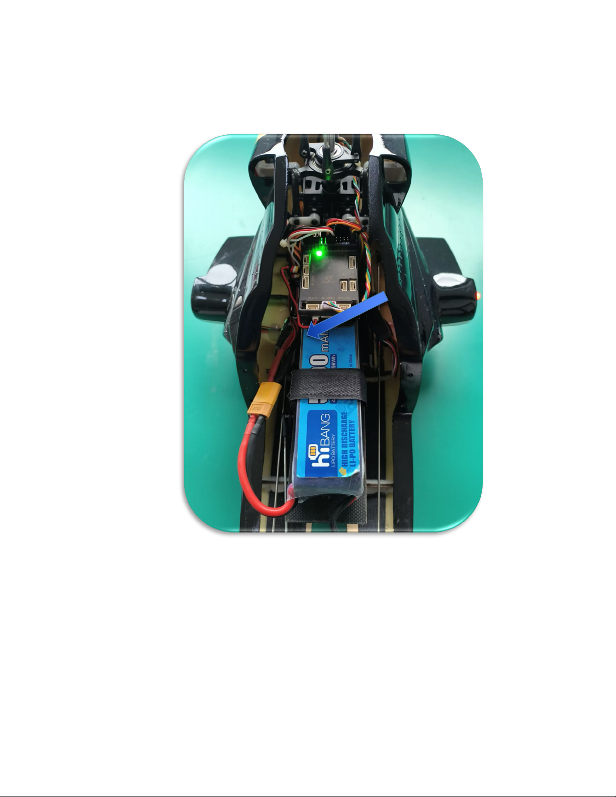
Installation of the battery
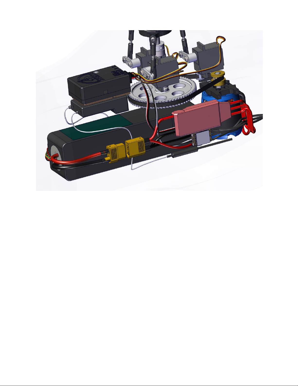
To begin the installation process, start by removing the nose cover to gain access to the product's interior. Install the battery on its
mount plate as shown and secure with the Velcro by tying it down with a bit of tension. The surface of the tray is rough, providing
enough grip to prevent it from moving if tied down properly.
© 2024 Roban All Rights Reserved. 17
Page 18
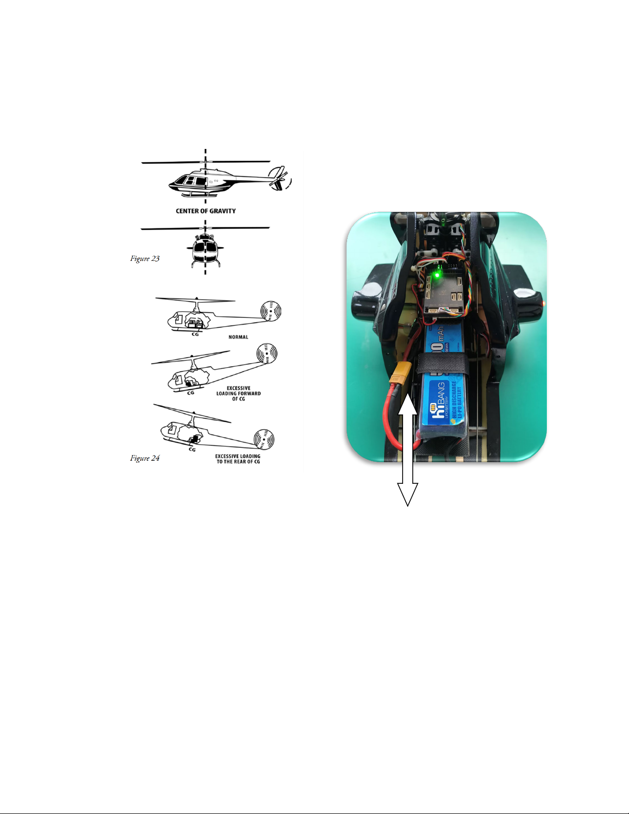
Center of gravity
Install the battery in the center of gravity as shown. Loosen the Velcro strap and move the battery forward of aft until, with the canopy
on, the helicopter is balanced, e.g. the main blades are perpendicular to the horizon. Lift the helicopter on the rotor cap and let it hang
freely and adjust until the main blades are level!
Mark the position with a sharpie for your convenience when you exchange batteries on the battery tray. Always secure the battery
with the Velcro firmly. It mustn’t come loose and move while in flight.
Page 19

Operation/Use
Charging the batteries
Before charging, ensure that you follow the battery operating instructions outlined in Section 3.3 of this manual to prevent damage
to the battery or charger. Proper handling and care during the charging process are crucial for maintaining the longevity and safety of
the battery. Follow the steps below carefully when using the lithium balance charger.
• Connect the charger to a power outlet (100-240VAC). Check the charger’s display for ‘000.’ This indicates the charger is
functioning correctly.
• Choose the correct charging port for your battery. For a 4S 14.8V battery, use the right-hand side port.
• The charger display will show the total voltage once connected.
• When charging is complete, disconnect the battery.
Once the display shows "FUL" and the fully charged voltage alternates on the display “168”, the battery is fully charged. Disconnect
the battery from the charger and unplug the charger from the power outlet.
Charger information
This charger operates with a low charge current. The battery supports charging at a 1C rate (full charge within 1 hour), which translates
to a 5A charge current or approximately 80W of real charging power. However, this charger has a rating of 1A, respectively 15W, so a
full charge may take up to 5 hours, depending on the battery's charge level. Please only use chargers specifically designed for RC
batteries with balance port (white plug) connectors under any circumstance. For safe charging, it is recommended to use a BAT-SAFE
charging enclosure.
© 2024 Roban All Rights Reserved. 19
Page 20
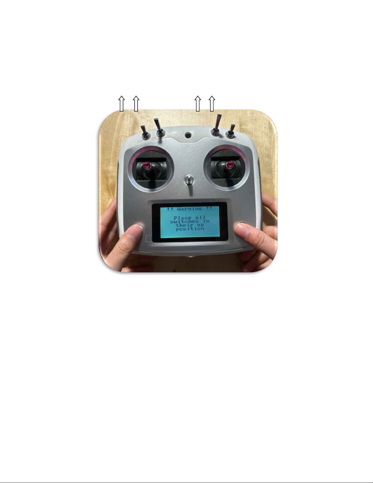
Switching the equipment on and off
Turn on the Transmitter
To power on the transmitter, insert 4 AA batteries (not included) into the battery compartment at the back. Next, press and hold both
power buttons simultaneously for two seconds to switch it on, and then release the buttons. In case you receive a warning message
regarding the switches, make sure to flip all four switches on the radio into the top position before switching on the transmitter to
avoid any startup issues.
Page 21
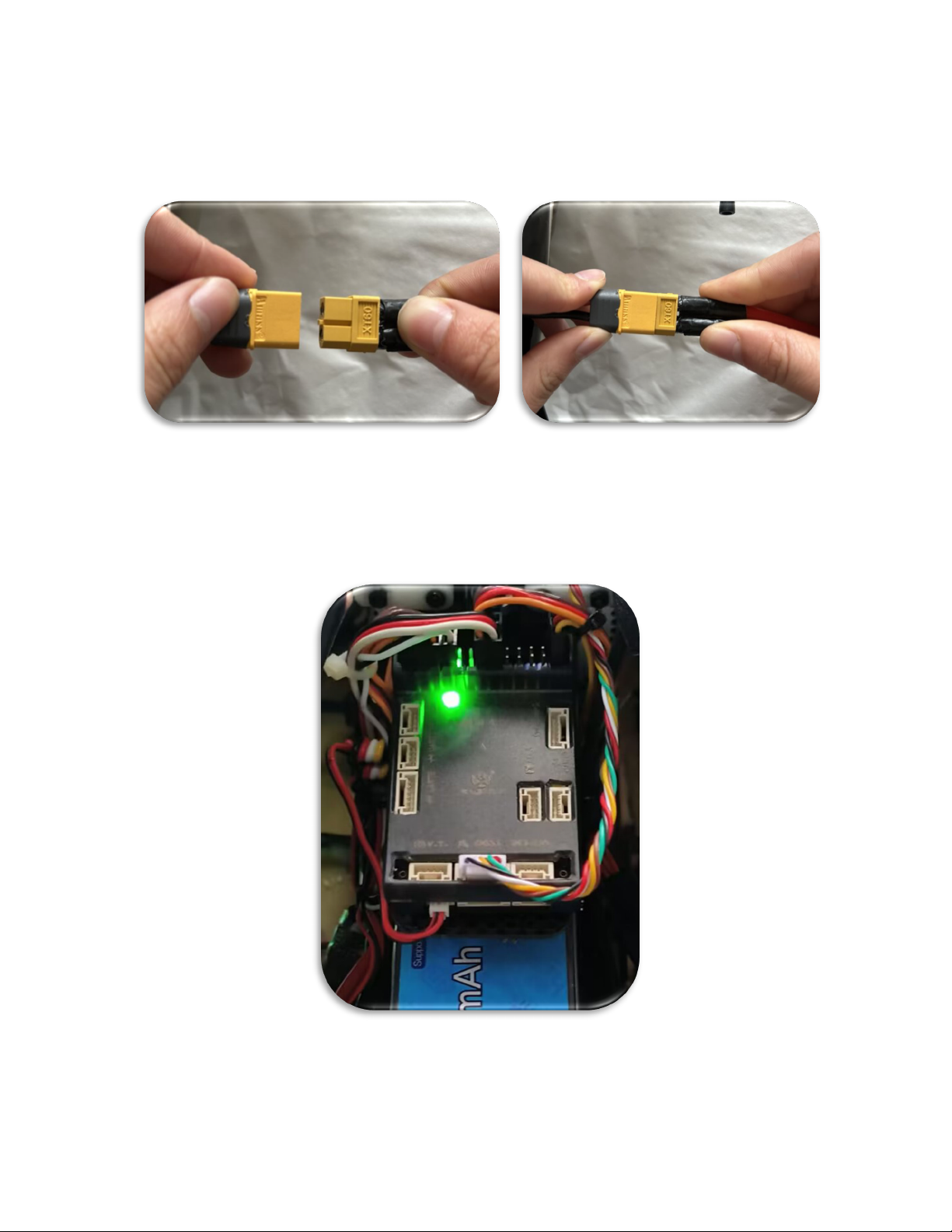
Turn on Helicopter
Install the battery at the appropriate center of gravity location and secure it using velcro straps, ensuring a tight fit. Position the
helicopter on a flat, level surface for takeoff, free of dust and debris. Connect the power plug as shown, ensuring a fully inserted
connection to prevent power loss during flight. Install the canopy.
Wait for the Controller initialization
The controller goes through a boot sequence. It will start flashing green/red, then red and finally flash green. With the mode switch
in the down (3D) position, you can actually start flying the machine, if you are a seasoned pilot. But let’s get started in the GPS mode.
So please make sure the mode switch is in the up (GPS) position. If indoors, you won’t be able to take off in GPS mode.
© 2024 Roban All Rights Reserved. 21
Page 22
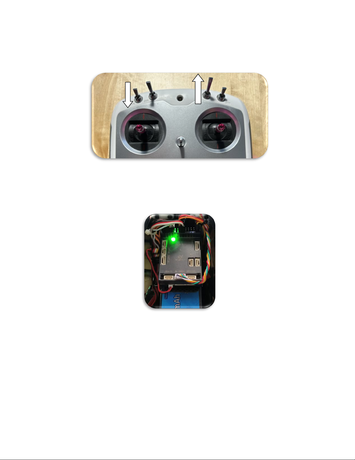
Getting ready to fly in GPS mode
Turn on the radio control with all levers in the up position. Dial the motor switch A in the down (STOP) position and leave the mode
switch in the up (GPS mode) position.
With the controller/helicopter being powered up already from the prior step, and the helicopter being indoors without a GPS signal,
the LED will double flash green or blue. This signals the absence of a sufficiently good GPS signal. Once you are outdoors and the GPS
signal is acquired, it will keep on flashing green in GPS mode, in the same way it flashes in the 3D or STABI mode switch positions with
a single flash.
Once the GPS position is locked, you will get a green single flash instead of a double blue flash in GPS mode. It may take up to 2
minutes to acquire a GPS signal. Leave the canopy off and observe, once you are used tho this startup procedure you basically just
wait for a moment until the GPS signal is acquired.
If the sky is blocked by clouds, use droneweather to check conditions. Without a good, high quality GPS signal the machine won’t let
you take off in GPS mode, but in both other flight modes.
Page 23
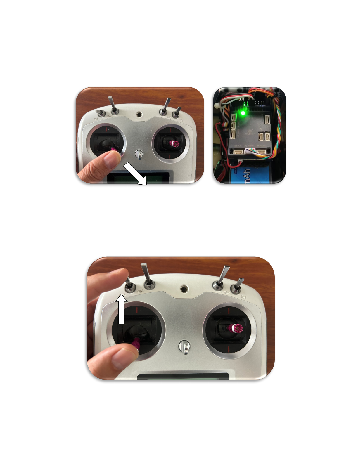
Arm the helicopter
The controller has a double arming feature to prevent accidental operation for your safety. Before you can start the motors, you must
arm the control unit. It’s done by a simple stick motion on your radio (left stick down and to the middle) and hold it there for 3 seconds.
The controller light will go from green single flash to permanent green. It is now armed. If there is no GPS signal and you have a double
flash, it won’t arm itself!
Start the motors
When you now flip the motor switch A UP, both the main and tail rotor (tail might not until the yaw stick or helicopter is moved) will
start to spool up. Otherwise the helicopter will disarm itself after 15 seconds and start to flash green again if the motors aren’t turned
on, so make sure that not too much time passes between arming from the prior step and switching on the motors. Do not switch off
the motors during flight, unless in emergency situations, as the helicopter will fall to the ground.
© 2024 Roban All Rights Reserved. 23
Page 24
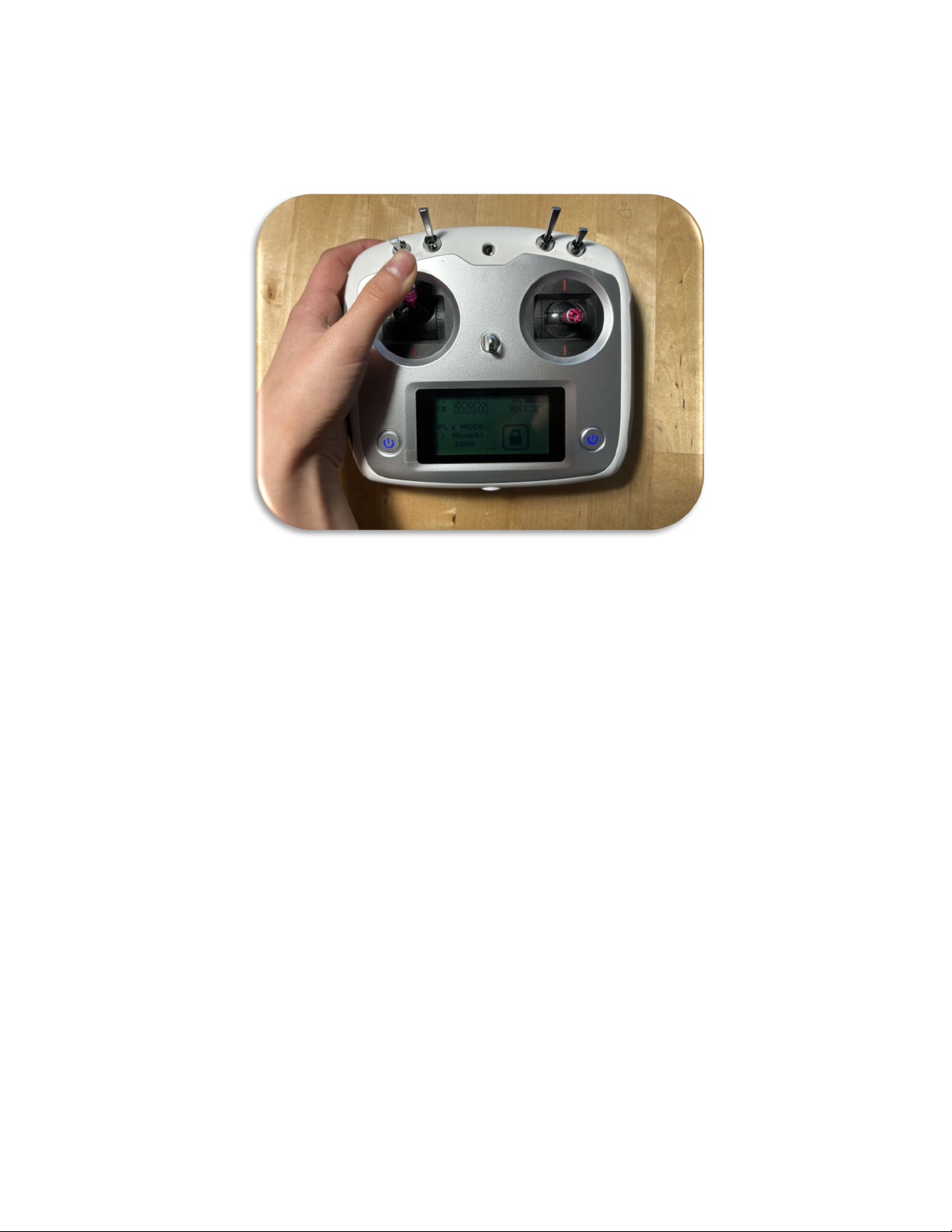
Fly the Helicopter
Once the main rotor is idling at constant speed (the rotor sound pitch doesn’t rise anymore), gently lift the helicopter by pushing the
lever upwards as shown, making sure to lift it to a height of at least 3 feet (1 meter) of clearance for safe hovering and maintaining
position. Its now up to you to fly and land the helicopter.
Page 25
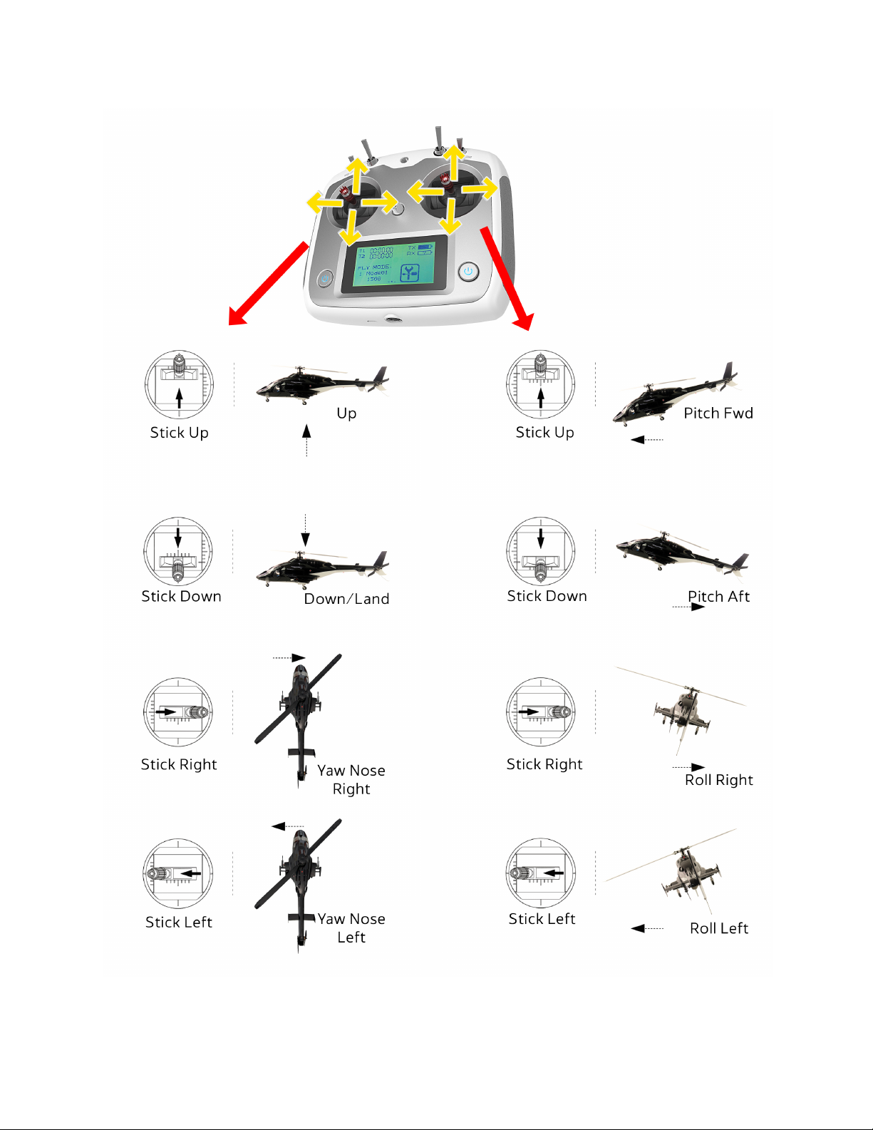
Flight maneuvers (MODE 2)
© 2024 Roban All Rights Reserved. 25
Page 26
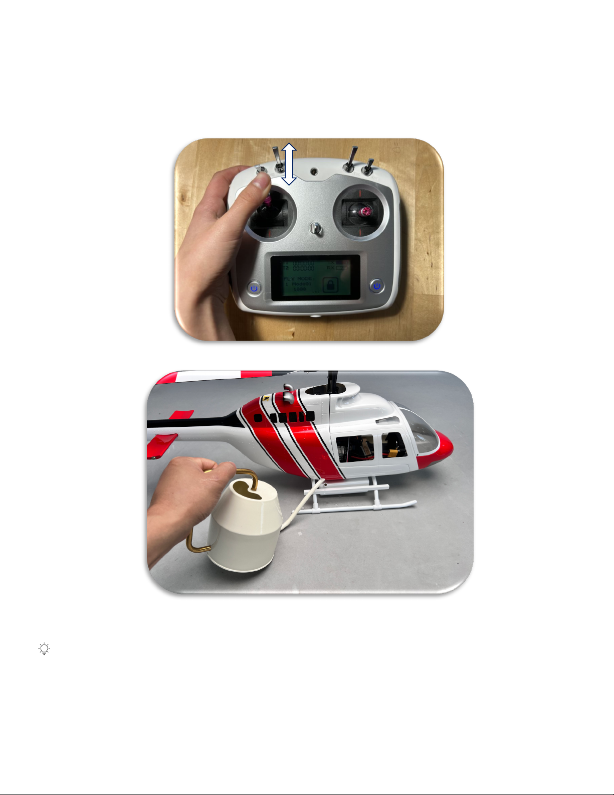
B-206 Water Tank Operation
The B-206 is equipped with fully working water tank that includes a water pump. Before powering on the helicopter, fill the water tank
with tap water until full. Do not seal the filling nozzle, air needs to enter freely when the pump is active, or the tank will get deformed.
Once airborne, you can activate the pump by flipping Switch B to the down (PUMP) position. Once the water has been emptied, turn
the pump off by switching the flip Switch B back into the upper (OFF) position.
The pumps parts are fully insolated from the water, there is not need for you to dry the tank before storage to prevent
rusting/oxidation.
Page 27
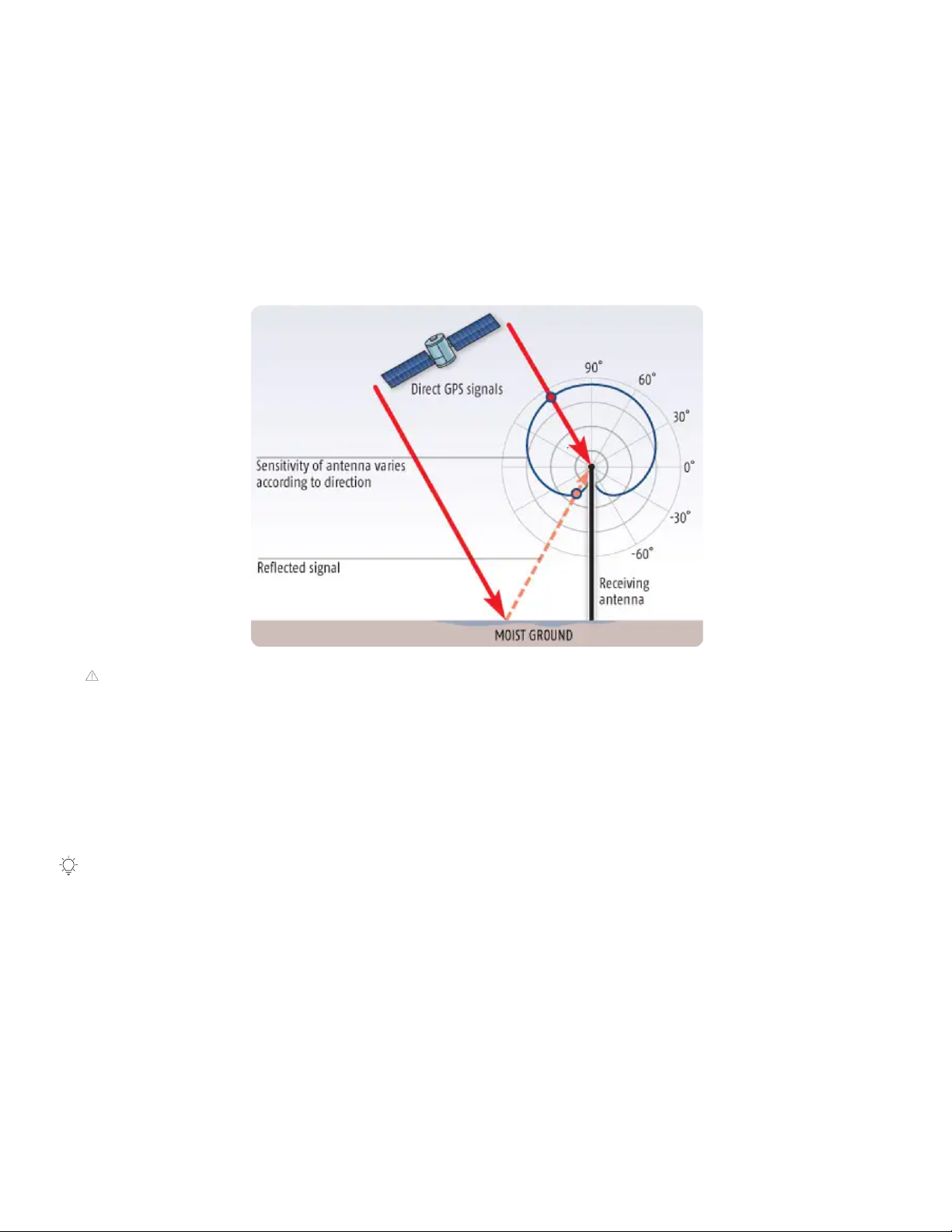
GPS near Ground Interference
We advise against hovering within 3 feet (1 meter) of the ground in GPS mode for extended periods. GPS relies on signals from
multiple satellites, calculating position based on the time it takes for these signals to reach the receiver. However, when flying close
to the ground, these signals can reflect off surfaces—such as moist gravel or concrete—and bounce back to the receiver, causing
inaccurate readings.
This phenomenon, known as multipath error in GNSS systems, becomes more pronounced as the antenna gets closer to reflective
surfaces. In the case of small radio-controlled aircraft, the risk of interference increases, potentially leading to erratic aircraft
movements. For optimal performance and safety, maintain a higher altitude when hovering in GPS mode.
For this reason, we strongly advise against operating in GPS mode near the ground, except during takeoff and landing.
Keep Track of Flight Time
With a fully charged battery, you can fly for up to 15 minutes before needing to land and recharge or replace the battery. Since the
controller maintains altitude using GPS, it may be difficult to notice when the battery is running low based on the helicopter’s flight
behavior alone.
We recommend timing your flight from the moment you turn the motors on. After about 12 minutes, start heading back to your
landing spot and prepare to land. The radio control has an integrated timer function that can be activated to display the flight time.
Instructions for using this timer are provided in the radio control section of this manual.
It is important to monitor the flight time to avoid activating the automatic landing feature triggered by low battery voltage.
© 2024 Roban All Rights Reserved. 27
Page 28
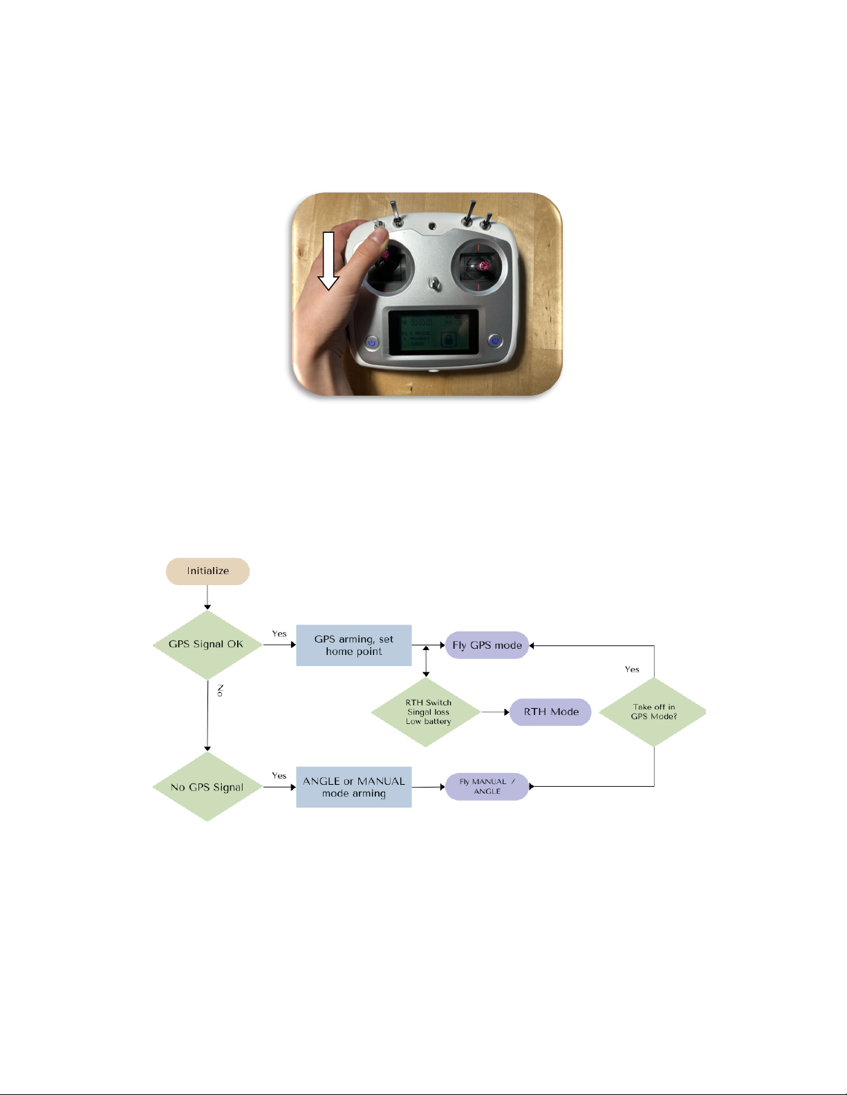
Landing the Helicopter
When you are ready to land, guide the helicopter to a suitable flat area, such as your original take-off spot, using the flight controls.
Gradually lower the helicopter until the landing gear touches the ground. Once the helicopter has landed, immediately shut off the
motors by flipping Switch A to the "Motor Off" position. Avoid leaving the helicopter with the blades spinning on the ground, except
during take-off or landing.
Flight Modes
Flight mode chart
Page 29
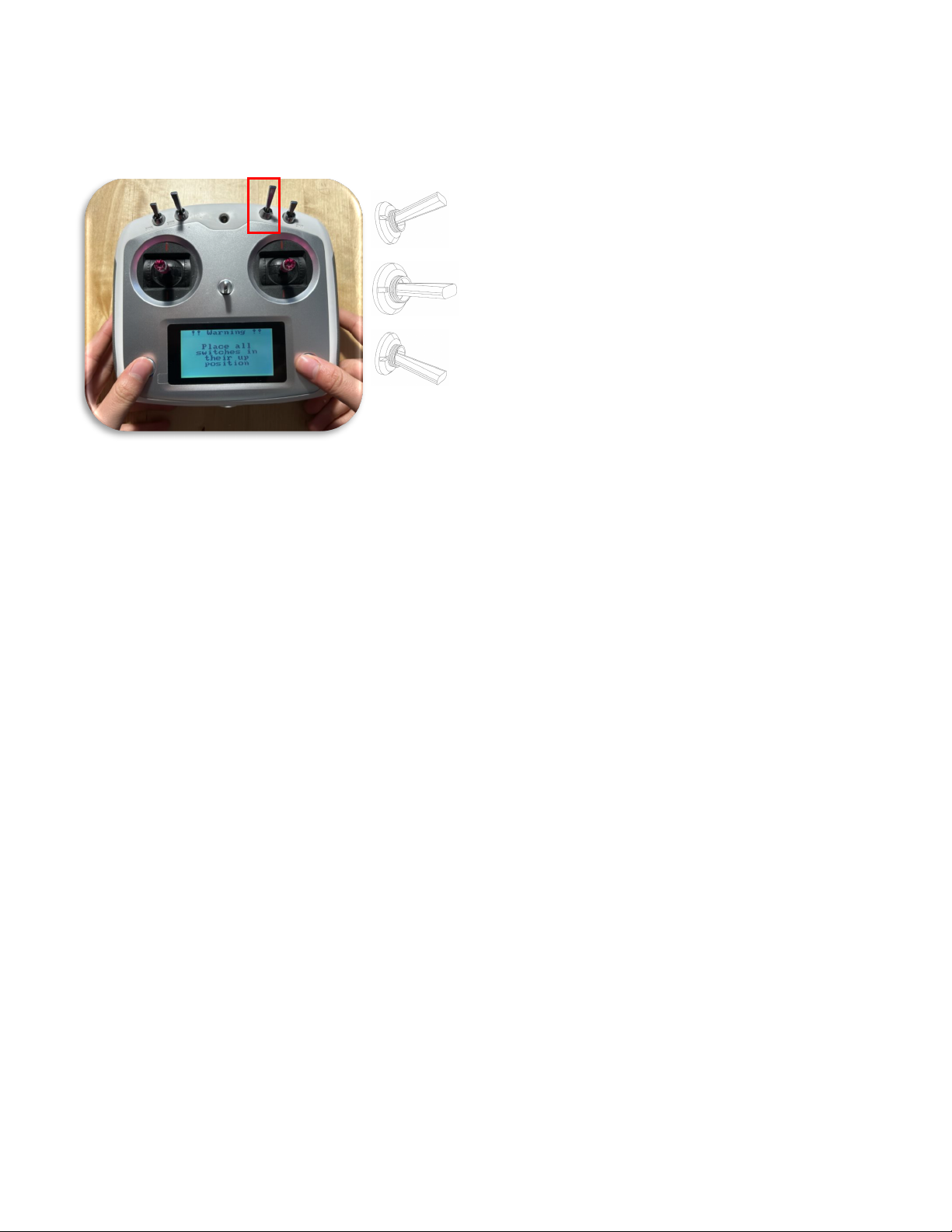
GPS MODE
ANGLE MODE
MANUAL MODE
Controller Flight Mode Description
The helicopter offers a variety of control modes, each of which produces a different flight performance of the aircraft. The flight mode
is controlled by Switch C, which offers three modes that can be switched between:
Additionally, from GPS mode you can enter the RTH MODE. The exact functionality is explained below.
Use cases for each mode
GPS Mode: Stable position and altitude, best for beginners.
ANGLE Mode: Self-leveling but requires manual control of height and position.
MANUAL Mode: Full manual control, no automatic stabilization or leveling.
RETURN TO HOME (RTH) Mode: Full automatic control, return to take off location, auto landing.
GPS Mode
In GPS mode, the helicopter uses the GPS sensor to stay in one place and keep the altitude as long as the control stick is not moving.
By moving the control sticks, you move the point and heading the 3D space, and the helicopter will automatically move to this new
location. All directions are fully controlled by the controller. This mode does not require constant control, you can leave your hands
off the control sticks, and it will stay steady in place, and even resist wind and keep the position. The GPS mode is dependent on the
GPS position signal, so a 3 x 3 x 3 ft tolerance window over time is within the actual specifications of accuracy.
Only if you take of in GPS mode the RTH Mode is accessible.
© 2024 Roban All Rights Reserved. 29
Page 30

ANGLE Mode
In angle mode, the helicopter does not use GPS to stay in one place, but stabilizes the helicopter by returning to a level attitude on
the roll and pitch axis if you let go of the control sticks. But it doesn’t control the position or height like in GPS mode. In Angle Mode,
the helicopter may drif in position and change its altitude, and you will need to control its movement manually. This mode requires
constant manual control.
We advise that you familiarize yourself with these control modes and use them appropriately to suit your flight needs.
If you switch from GPS to Manual or Angle mode while hovering, the helicopter may drop in altitude. Be prepared to compensate
by manually adjusting the throttle.
Note: If you take off in Angle mode, the Return to Home function will not work. You must take off in GPS mode for this feature to
be available.
Manual Mode
In this mode, you have full control. The helicopter does not use GPS to stay in one place, nor self-stabilization via accelerometers. As
a result, you will need to control everything, including altitude and direction as any regular 3D helicopter. The model will keep the
angle on each rotational axis stable as long as the stick of the according axis is in the center postion, as any typical 3D helicopter gyro
for 3 axis offers. If you took off in this mode, the return to home function cannot be activated. This mode also allows for the highest
overall flight speeds in any direction but requires constant manual input.
When you switch from GPS mode to 3D mode during flight, the helicopter will drop in altitude because it loses the automatic height
adjustment. Be ready to control it manually to prevent a crash. Compensate for this by making an upward pitch stick movement if you
see the machine dropping, and a downward movement if the machine climbs. Keep in mind that this maneuver can be dangerous if
you're a novice, especially if you're close to the ground. Only experienced pilots will be able to quickly adjust for the loss of auto
altitude hold function.
In 3D mode, the helicopter does not automatically maintain its position, so it may drift in any direction. You'll need to compensate for
this movement manually. We strongly advise that you have ample flight experience and skills before attempting to use 3D mode.
If you switch from GPS to Manual or Angle mode while hovering, the helicopter may drop in altitude. Be prepared to compensate
by manually adjusting the throttle.
Note: If you take off in Manual mode, the Return to Home function will not work. You must take off in GPS mode for this feature
to be available.
Return to Home (RTH) Mode
This functionality is only available if the machine was armed and taken off in GPS mode only. It is not accessible if you armed the
machine in Manual or Angle mode.
It is an automated flight control that will return the aircraft to the take off point, land it and shut off the motors. There are several
ways to enter this mode, either manually or by a safe-guard automation. Once engaged, the aircraft will rise to 15m above the starting
point flying height, then turn into the home point heading and then fly towards the home point. Once the home point is reached, it
will turn the tail back into the take-off heading, then lower the altitude at a constant sink rate until it has landed and then switch off
the motors.
Page 31
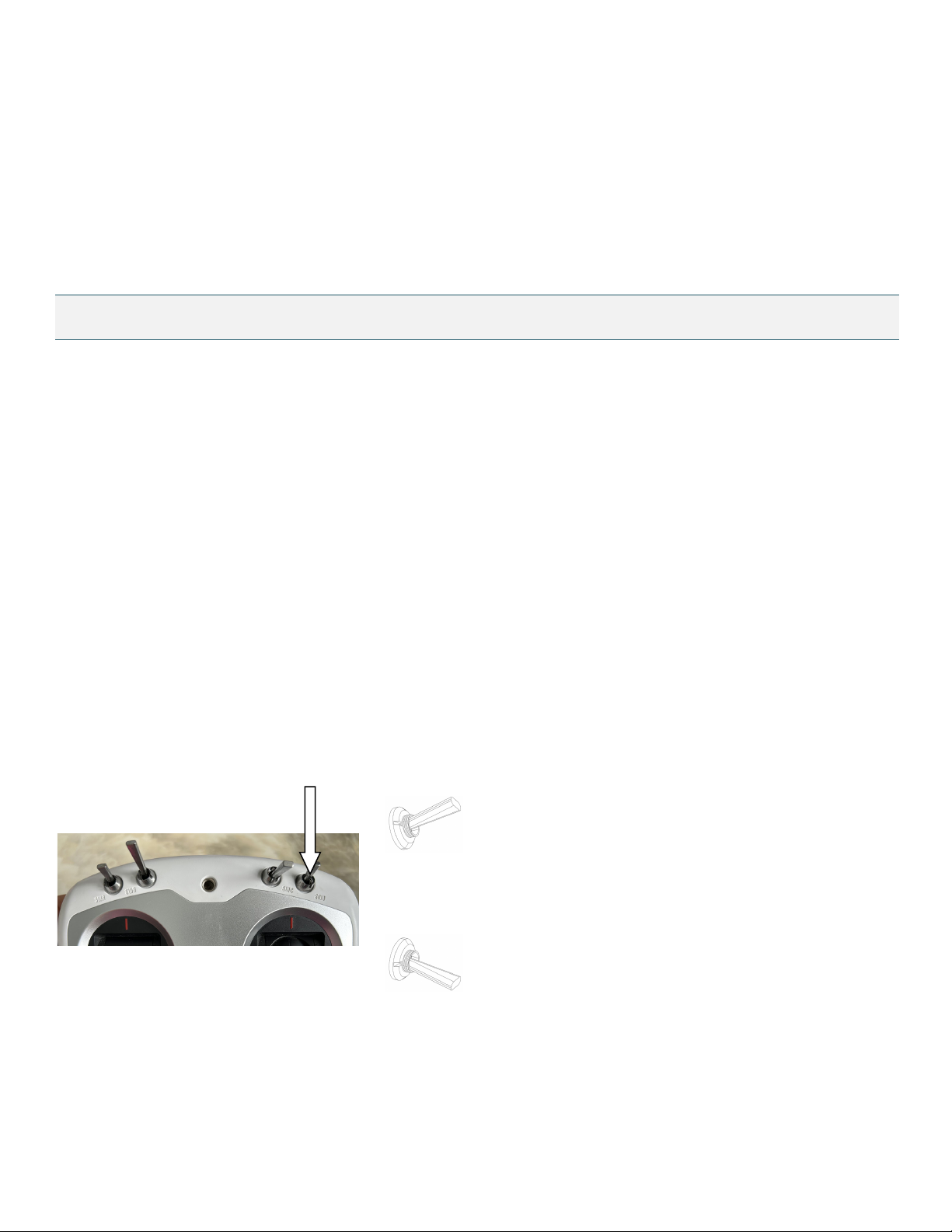
OFF
RETURN TO HOME
While the machine is in its decent phase after reaching the home point, its possible to adjust the position via the pitch and roll control
sticks to get the exact position right.
The RTH mode can be interruped manually. The radio control mode switch has to be in the GPS position and the RTH switch has to
be flipped into the RTH position and then back into the OFF position. This will interrupt the RTH mode.
Please note that while in return to home mode, the helicopter cannot detect or avoid obstacles, so it is necessary to ensure that there
are no obstacles between you and the starting point.
The controller offers three different ways to engage the RTH function:
Loss of Signal:
If the machine was unlocked and taken off in GPS mode, and the transmitter signal is interrupted for more than 3 seconds, the flight
control system will enter the RTH mode. It will take control of the helicopter via the RTH mode and automatically land and shutoff
unless interrupted by the user. This only will be possible if the radio signal returns to normal during the return flight, and the user can
turn on (while being in GPS mode) the RTH mode and off again during the return flight.
Low Voltage Return:
If the machine was unlocked and taken off in GPS mode, and the flight control detects that the flight battery has a too low voltage,
the controller will engage the RTH mode. In low voltage situations, the motor may not be able to output enough power to maintain
altitude and eventually lead to the helicopter falling, crashing, or getting damaged. To prevent this danger caused by insufficient
battery voltage, the flight control system will judge whether the current voltage is sufficient. If the actual voltage falls below the
programmed threshold, the helicopter will automatically enter the RTH. The user can turn on (while being in GPS mode) the RTH mode
and off again during the return flight.
On Command Return:
In the flip is switched into RTH postion (down), the model will also execute the return to home maneuver.
© 2024 Roban All Rights Reserved. 31
Page 32
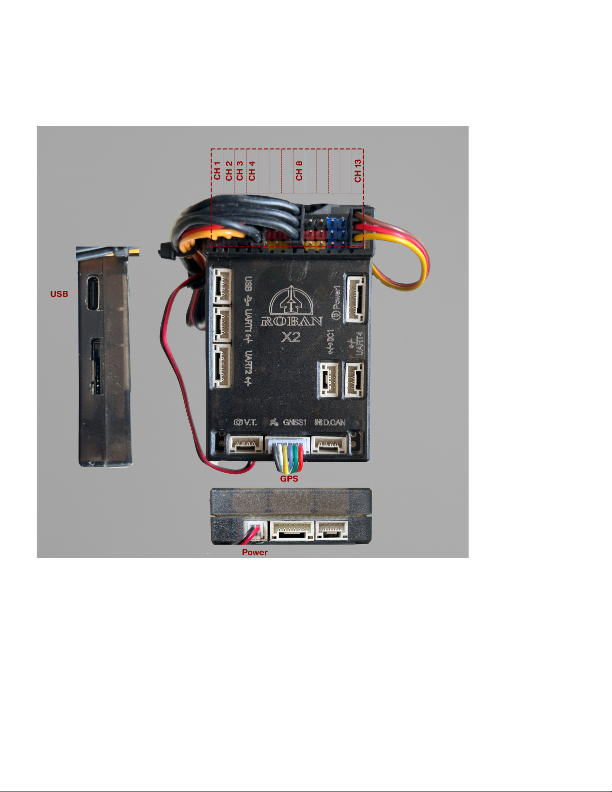
Electronic components and documentation
Controller ports and description
PCB Schematics – APM Roban X2 / F407
Page 33

Port name
Connected to
Ch1
Swash servo 1 (Powered by Main Motor ESC)
Ch2
Swash servo 2 (Powered by Main Motor ESC)
Ch3
Swash servo 3 (Powered by Main Motor ESC)
Ch4
Tail Motor ESC
Ch 5
Water pump contactor
Ch 6
LED light
Ch8
Main Motor ESC (7.4Vdc by ESC)
RC.In
Receiver (5Vdc internal step down)
Batt.In
Battery plug (14.8Vdc Input)
GPS1
GPS sensor
Green, solid
GPS mode, armed
Green, flashing
GPS mode ready, not armed, GPS signal acquired
Blue, double flash
GPS is acquiring position
Red, flashing slow
Compass calibration required/Magnets present
Red, flashing fast
No receiver signal present
Blue, solid
Manual/Angle mode ready, armed
Controller Port Wiring and Specifications
The controller can be powered either through the Batt.In connector or the USB connector.
An internal step-down converter provides 5V DC from the Batt.In connector to power the RC.In receiver port, which is isolated from
the other channels.
The servo and ESC channels share a common power and ground connection, but do not have their own internal power supply. Instead,
the ESC supplies power to the servos through a 7.4V DC BEC in a high-voltage configuration.
Note that the power connector is not polarity-protected.
Channels 1 through 10 are bridged for power and ground and must be supplied with power from an external source, such as the ESC.
Channel 13 (the receiver port) is powered internally by a 5V DC supply.
Controller status light description
© 2024 Roban All Rights Reserved. 33
Page 34
Blue, flashing
GPS signal acquired, Manual/Angle mode ready, not armed
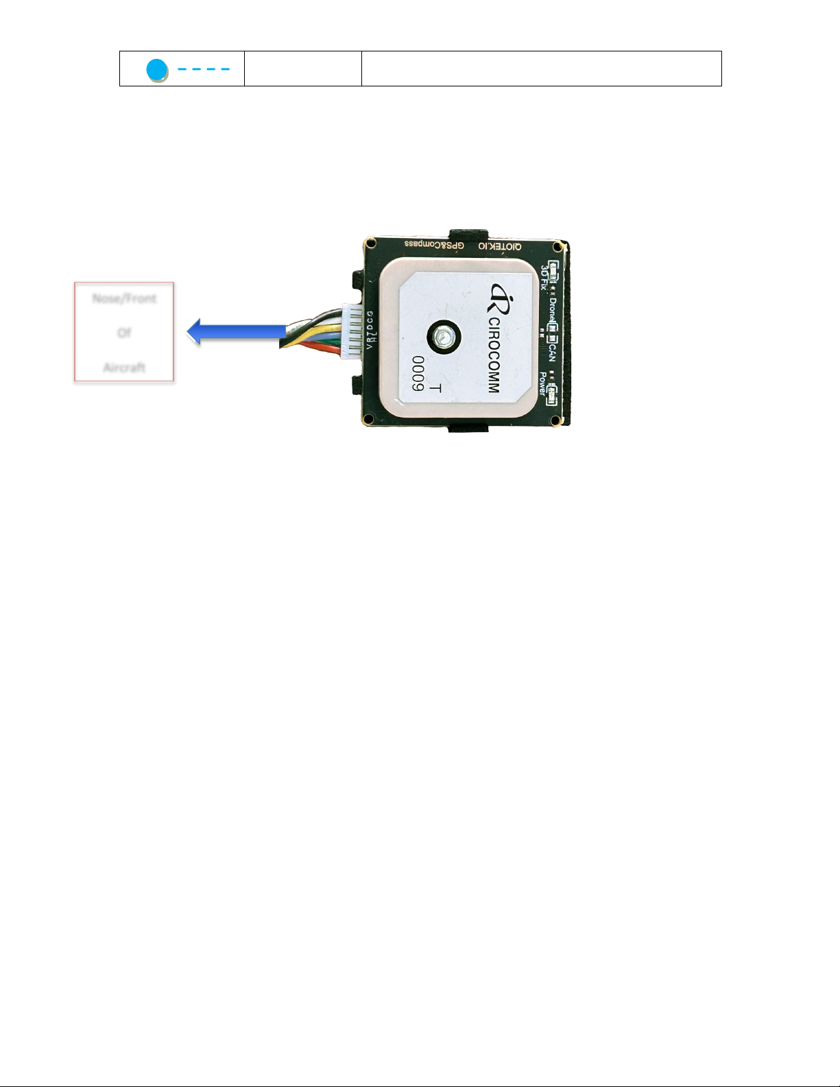
GPS Sensor
Nose/Front
Aircraft
The GPS sensor is a U-blox M10N unit with an onboard magnetometer, which is the only magnetometer used in the system. It is
installed in the tail boom to avoid magnetic interference from the main motor. For optimal performance, ensure the antenna is level
and properly aligned, with the plug facing toward the nose of the aircraft. The unit is preinstalled and doesn’t require any maintenance.
The unit is automatically configured during bootup of the controller.
Of
Page 35
Battery
Connector
Main Motor
Connector
Flight
onnector
Tail ESC
Signal
Tail Motor
Connector
Main ESC
7.4Vdc
Dual channel ESC
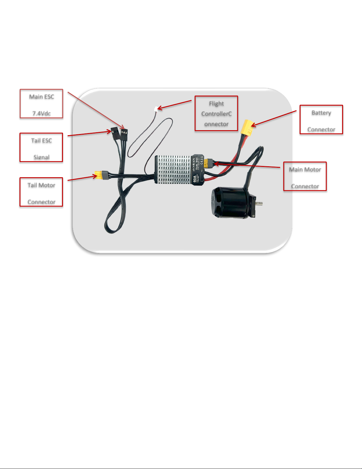
The supplied ESC is a dual-channel unit, consisting of a helicopter-governor-type main ESC and a fast-responding BLHeli-type tail rotor
ESC. Both are physically separated and operate independently, each controlled by its own MCU within the controller. Additionally, the
ESC includes a DC-DC buck step-down voltage converter that supplies 7.4V DC to the servos through the controller’s bridged
connectors, spanning channels 1 through 8. Below is the wiring schematic:
ControllerC
© 2024 Roban All Rights Reserved. 35
Page 36
Swash Servos designation and wiring
Ch3
Ch1
Ch2
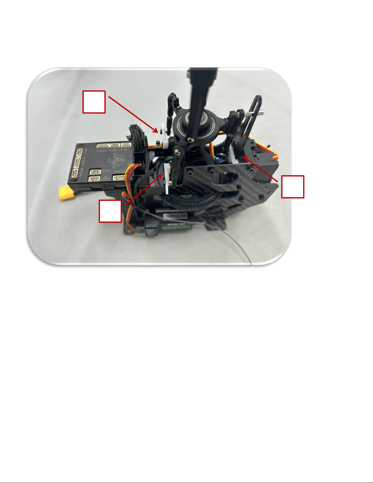
The swashplate servos are connected to the ports 1-3 of the controller. The servos are HV (7.4Vdc) servos, which are powered by the
dual ESC connected on port Ch8.
Page 37
LED Light system
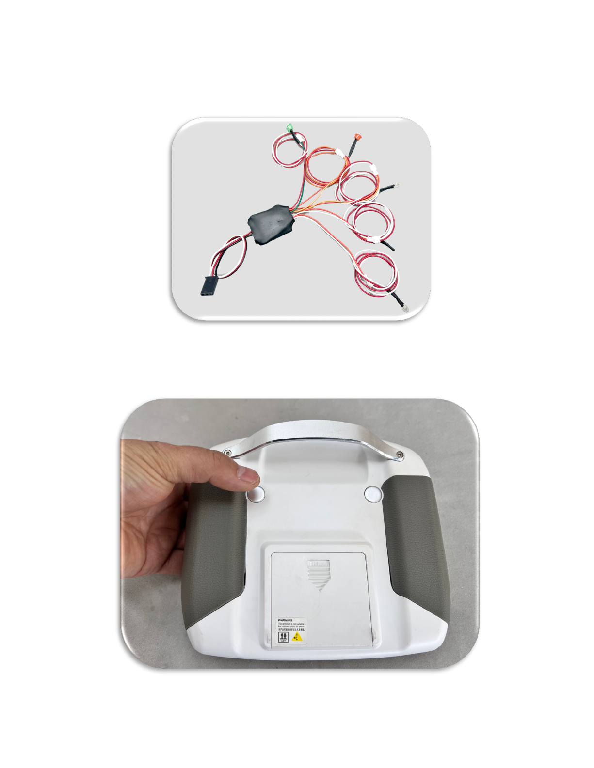
The helicopter comes equipped with a preinstalled LED light system, which has its own dedicated controller. The system is powered
by the 7.4V BEC supply through the bridged rail on the main controller, and is connected to servo port 6.
The LED controller can be controlled by the radio control. The right-hand side switch on the back side of the radio can be used to cycle
through 8 different patterns. The position light pattern always starts on the same pattern mode on power up. The controller is separate
from the main controller and can be controlled immediately.
© 2024 Roban All Rights Reserved. 37
Page 38

Troubleshooting, Support and Warranty
Adjusting the controller
The controller is based on the ArduCopter Heli open-source software. To modify the parameters, you can use the APM Mission Planner,
which is available for iOS, Windows, and Linux. It connects via USB (or optionally through a wireless WiFi connection).
We provide a separate manual and video tutorials covering the usage of the software and the setup process in detail. The ArduCopter
platform offers a wide range of features, and many parameters are accessible for adjustment. However, we recommend making
changes only when necessary, such as after replacing servos that require setpoint adjustments.
For further guidance, please visit our website at www.robanmodel.com . On the product page, you will find links to the control
software manuals and support videos.
Helicopter blade tracking and maintenance
The helicopter comes fully adjusted, so no blade tracking is necessary. If you use our original rotor blades, even replacing a set will not
require blade retracking.
Blade tracking refers to the process of ensuring that both rotor blades follow the same path during rotation. Misaligned blades can
cause vibrations and reduced flight stability. Typically, blade tracking involves adjusting the pitch of one or both blades to make sure
they rotate in the same plane.
However, if a mishap damages the blades, or bends the rotor grips or grip link connectors, it can misalign the control system. In such
cases, we recommend replacing the grips and pitch levers as well.
For this specific helicopter, there is no need to adjust blade tracking as the control system is non-adjustable. After a crash, the only
thing you may need to verify with a pitch gauge is that the swashplate is still level. Adjust any necessary center points through the
controller software interface, rather than making mechanical adjustments to the helicopter itself.
Technical support
For technical support, product queries, or warranty claims, please contact:
Technical Support & General Inquiries:
- Email: [email protected]
When contacting support, please have the following details ready:
- Product model and serial number
- Description of the issue
- Steps you’ve already tried for troubleshooting
Warranty and Replacement Process
If your product is within the warranty period and requires repairs or replacement, follow these steps:
• Contact the support team of you point of purchase via email or phone.
• Follow shipping instructions provided by their team.
Page 39

Product Compliance and Conformity
Product Compliance
FCC Information
FCC ID: Transmitter: N4ZFLYSKYI6S, Receiver: N4ZFLYSKYIA10
Supplier's Declaration of Conformity
Roban MD-500E 470 (HSM-470-R-MD)
This device complies with part 15 of the FCC Rules. Operation is subject to the following two conditions: (1) This device may not cause harmful interference, and (2) this device must accept
any interference received, including interference that may cause undesired operation.
CAUTION: Changes or modifications not expressly approved by the party responsible for compliance could void the user's authority to operate the equipment
NOTE: This equipment has been tested and found to comply with the limits for a Class B digital device, pursuant to part 15 of the FCC Rules. These limits are designed to provide reasonable
protection against harmful interference in a residential installation. This equipment generates, uses, and can radiate radio frequency energy and, if not installed and used in accordance with
the instructions, may cause harmful interference to radio communications. However, there is no guarantee that interference will not occur in a particular installation. If this equipment does
cause harmful interference to radio or television reception, which can be determined by turning the equipment off and on, the user is encouraged to try to correct the interference by one or
more of the following measures:
• Reorient or relocate the receiving antenna.
• Increase the separation between the equipment and receiver.
• Connect the equipment into an outlet on a circuit different from that to which the receiver is connected.
• Consult the dealer or an experienced radio/TV technician for help.
Motion RC, LLC, , Cary, IL 61822
Email: [email protected]
Web: motionrc.com
Compliance Information for the European Union:
Roban 470 MD-500E (HSM-470-R-MD)
Hereby, Roban Model Limited declares that the device is in compliance with the following: EU Low Voltage Directive 2014/35/EU, EU EMC Directive
2014/30/EU , EU Radio Equipment Directive 2014/53/EU, RoHS 2 Directive 2011/65/EU, RoHS 3 Directive -Amending 2011/65/EU Annex II 2015/863
NOTE: This product contains batteries that are covered under the 2006/66/EC European Directive, which cannot be disposed of with normal
household waste. Please follow local regulations. The full text of the EU declaration of conformity is available at the following internet address:
https://www.robanmodel.com/content/rendercompliance
Wireless Frequency Range and Wireless Output Power:
FlySky Transmitter 6157A-KATY1T, 2478 MHz 17.7dBm
FlySky FS-iAB6 Receiver 6157A-WACO1T, 2404 – 2476 MHz 1.43dBm
WEEE NOTICE: This appliance is labeled in accordance with European Directive 2012/19/EU concerning waste of electrical and electronic equipment (WEEE). This
label indicates that this product should not be disposed of with household waste. It should be deposited at an appropriate facility to enable recovery and recycling.
EU Manufacturer of Record: Roban Model Limited, Shiwan, Huizhou, Guangdong, PR China
© 2024 Roban All Rights Reserved. 39
Page 40

Software Licensing and Attribution:
The controller used in this product is based on software licensed under the Creative Commons Attribution-ShareAlike 3.0 (CC BY-SA
3.0) license. As per the license requirements, we provide the following attribution details:
• Creator: ArduPilot Development Team
• Attribution Parties: ArduPilot contributors
• Copyright Notice: © ArduPilot
• License Notice: This software is licensed under the Creative Commons Attribution-ShareAlike 3.0 License.
• Disclaimer Notice: This software is provided "as-is" without any warranty. For details on the terms of use, refer to the full
license.
• Link to Material: You can access the original source of the software and further details about the license at
https://ardupilot.org.
• Title: ArduCopter Heli
For more details on the CC BY-SA 3.0 license, please visit the official Creative Commons website at
https://creativecommons.org/licenses/by-sa/3.0/.
Page 41
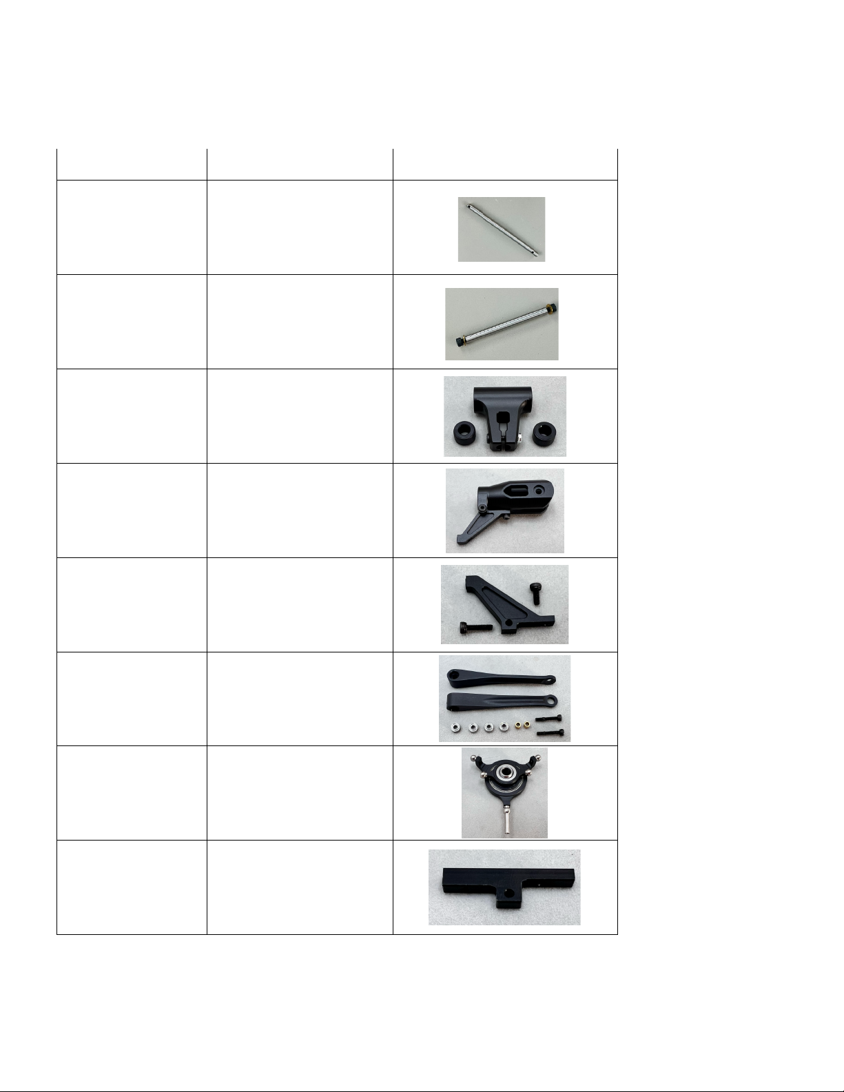
Sparepart No
Description
Picture
HSM-470-SP001
Main shaft
HSM-470-SP002
Feathering shaft
HSM-470-SP003V2
Main rotor hub
HSM-470-SP004V2
Main blade grip
HSM-470-SP005V2
Rotor holder arm
HSM-470-SP006V2
Upper swash idler
HSM-470-SP007V2
Swash plate 2B
HSM-470-SP008
Servo holder 1
Appendix A. Mechanical Spare Parts
Parts may be listed with different prefix (RBN-470 or HSM-470)
© 2024 Roban All Rights Reserved. 41
Page 42
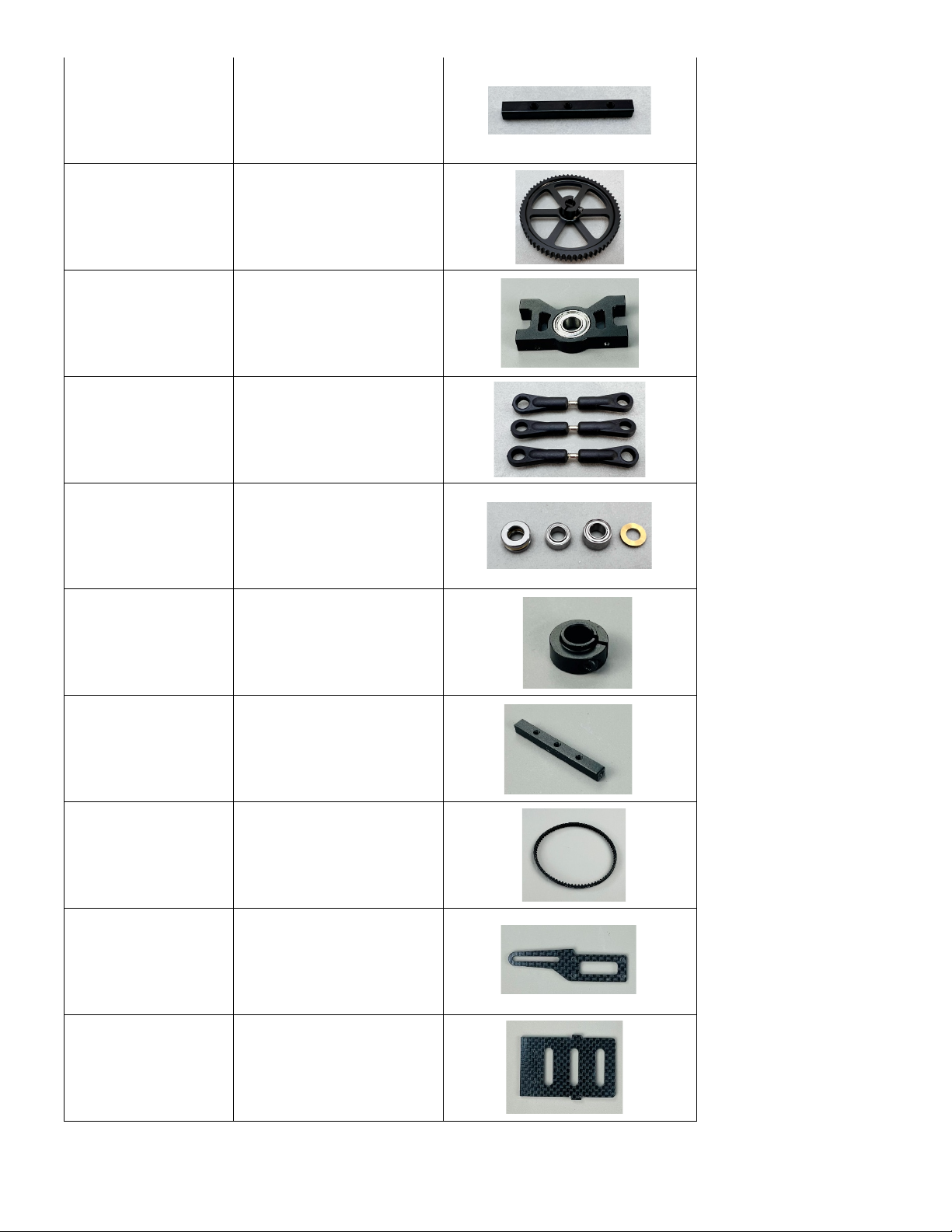
HSM-470-SP009
Servo holder 2
HSM-470-SP010V2
Main gear
HSM-470-SP011
Main shaft bearing block
HSM-470-SP012V2
Lower linkages
SM-470-SP013
Bearing set
HSM-470-SP014
Main shaft lock
HSM-470-SP015
Main frame spacer
HSM-470-SP016
Main Belt
HSM-470-SP017
Lower swash bracket
HSM-470-SP018
Tail motor mount (3D)
Page 43
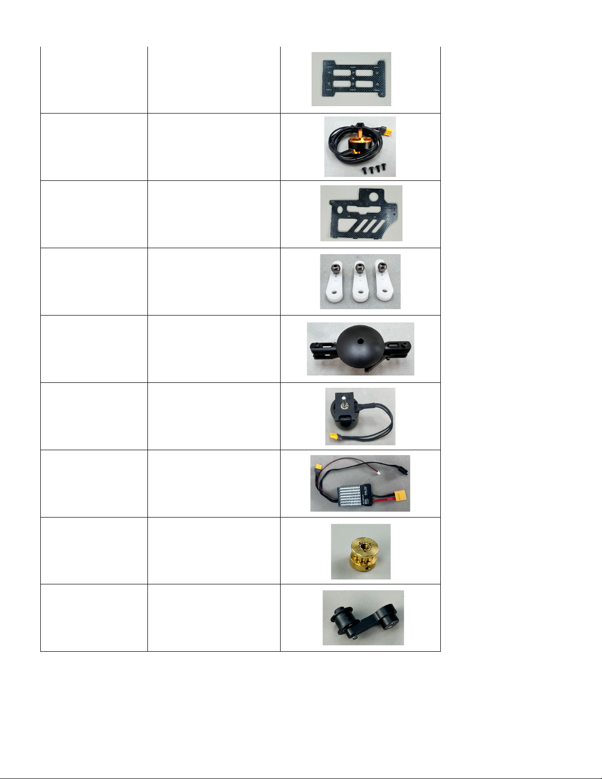
HSM-470-SP019
Main frame bottom
HSM-470-SP020
Tail Motor with wire + plug
HSM-470-SP021
Main frame set
HSM-470-SP023
Servo horn set
HSM-470-SP024
Complete rotorhead
HSM-470-SP028
Main motor incl mount
HSM-470-SP030
ESC combo
HSM-470-SP032
Motor belt pulley
HSM-470-SP033
Belt tensioner
© 2024 Roban All Rights Reserved. 43
Page 44
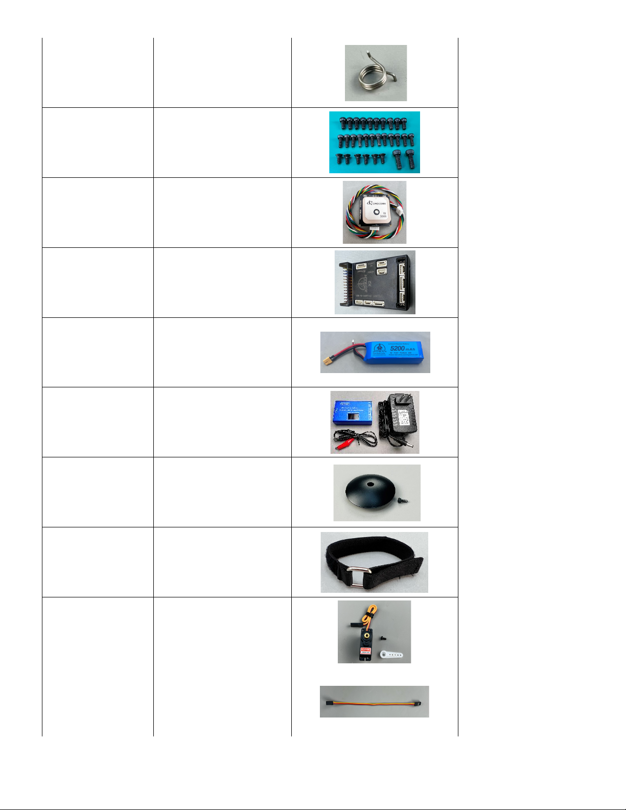
HSM-470-SP034
Tensioner spring
HSM-470-SP035
Fastener set
HSM-470-SP036
GPS Sensor
HSM-470-SP037
Controller
HSM-470-SP038
4S 5200mah battery
HSM-470-SP029
Balance charger
HSM-470-SP040
Rotor cap
HSM-470-SP041
Battery vercro
HSM-470-SP042
Servo CW
HSM-470-SP044
Servo wire RX to Controller
Page 45
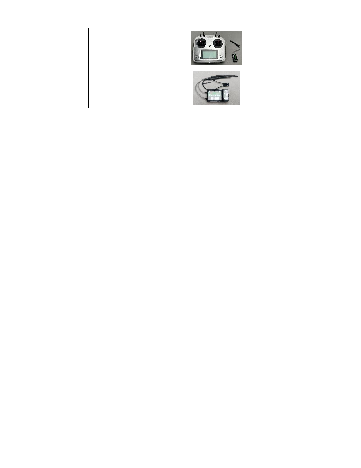
HSM-470-SP047
Transmitter / Receiver Set
HSM-470-SP048
Receiver standalone
© 2024 Roban All Rights Reserved. 45
Page 46
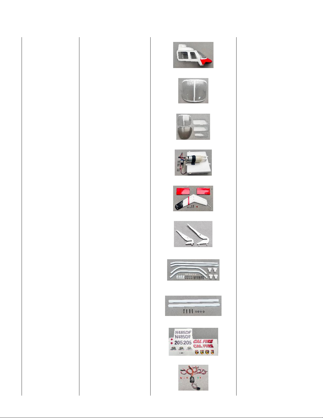
Appendix B. Scale Spare Parts
HSM-BE470LPJ001
470L BELL206 canopy
HSM-BE470LPJ002
470L BELL206 front window
HSM-BE470LPJ003
470L BELL206 all window
HSM-BE470LPJ004
470L BELL206 water tank
HSM-BE470LPJ005
470L BELL206 tail fins
HSM-BE470LPJ006
470L BELL206 scale part set
HSM-BE470LPJ007
470L BELL206 landing gear
HSM-BE470LPJ008
470L BELL206 footrest
HSM-BE470LPJ009
470L BELL206 decals
HSM-BE470LPJ010
470L BELL206 light kit
Page 47
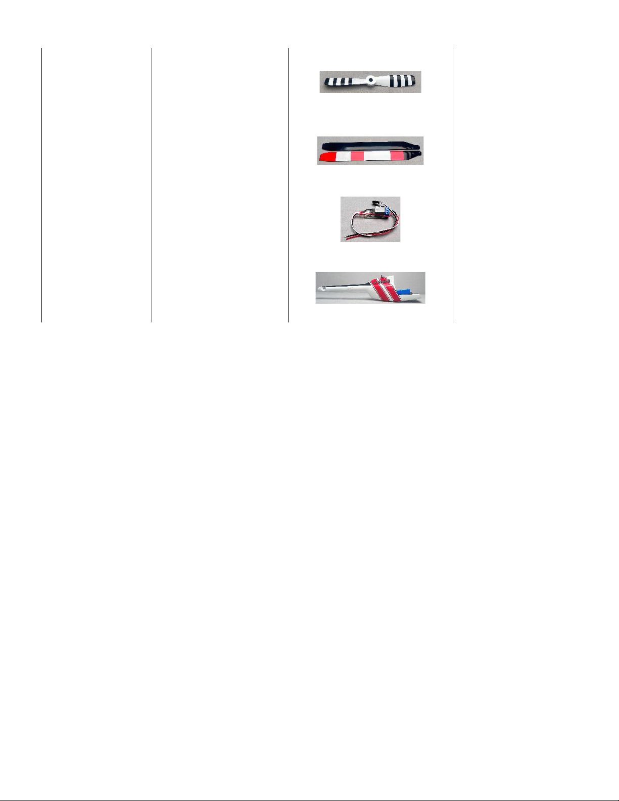
HSM-BE470LPJ011
470L BELL206 tail blades
HSM-BE470LPJ012
470L BELL206 main blades
HSM-BE470LPJ013
470L BELL206 pump
controller
HSM-BE470LPJ014
470L BELL206 aft body
© 2024 Roban All Rights Reserved. 47
Page 48
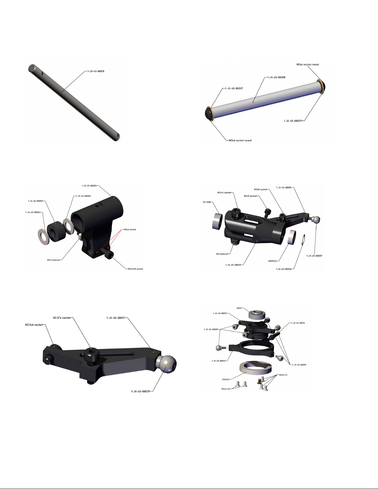
Appendix C. Spare parts explosion drawings
HSM-470-SP001 HSM-470-SP002
HSM-470-SP003 HSM-470-SP004
HSM-470-SP005 HSM-470-SP007
Page 49
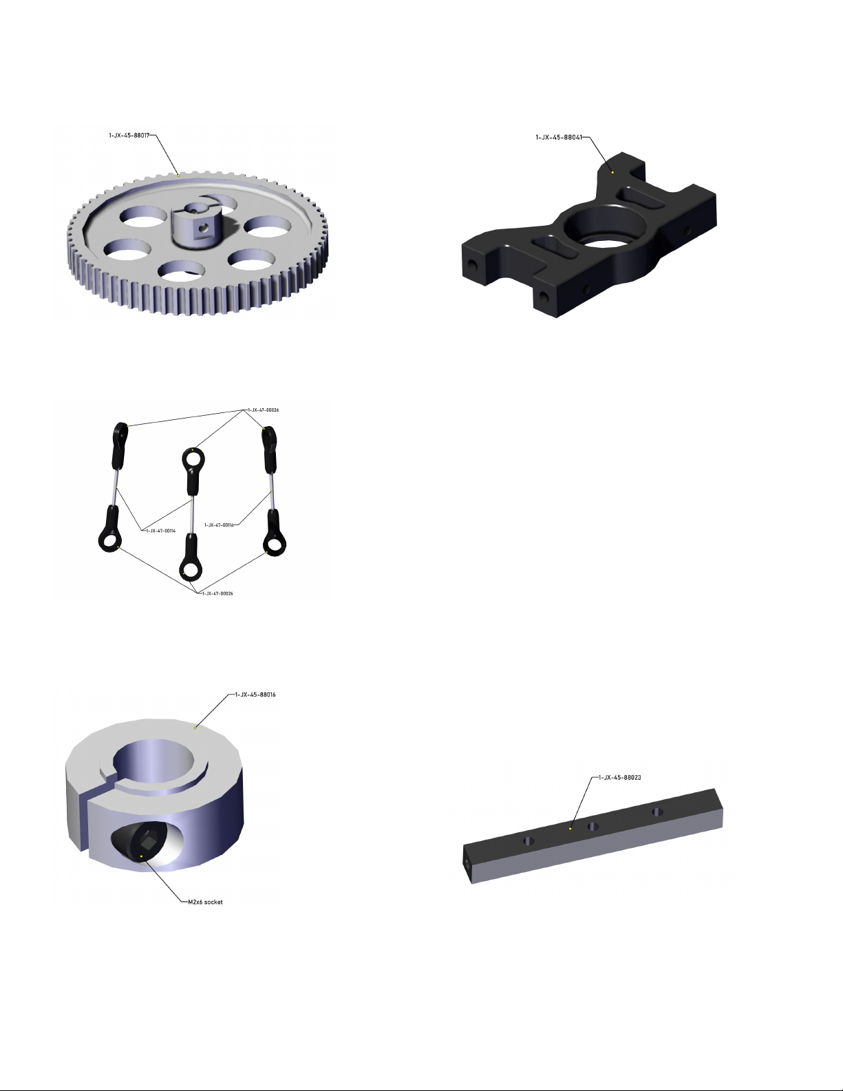
HSM-470-SP010 HSM-470-SP011
HSM-470-SP012
HSM-470-SP014 HSM-470-SP015
© 2024 Roban All Rights Reserved. 49
Page 50
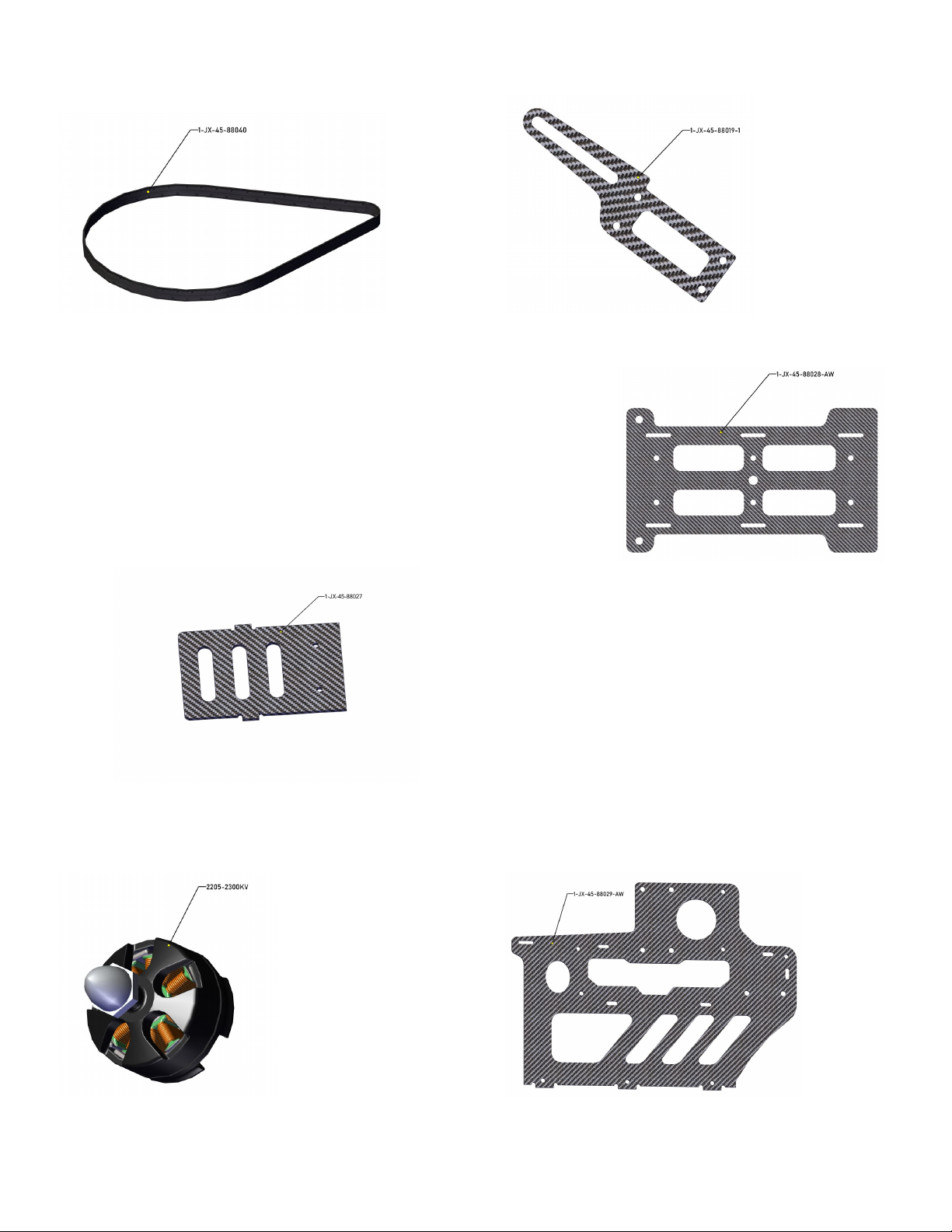
HSM-470-SP016 HSM-470-SP017
HSM-470-SP019 HSM-470-SP020
HSM-470-SP020 HSM-470-SP021
Page 51
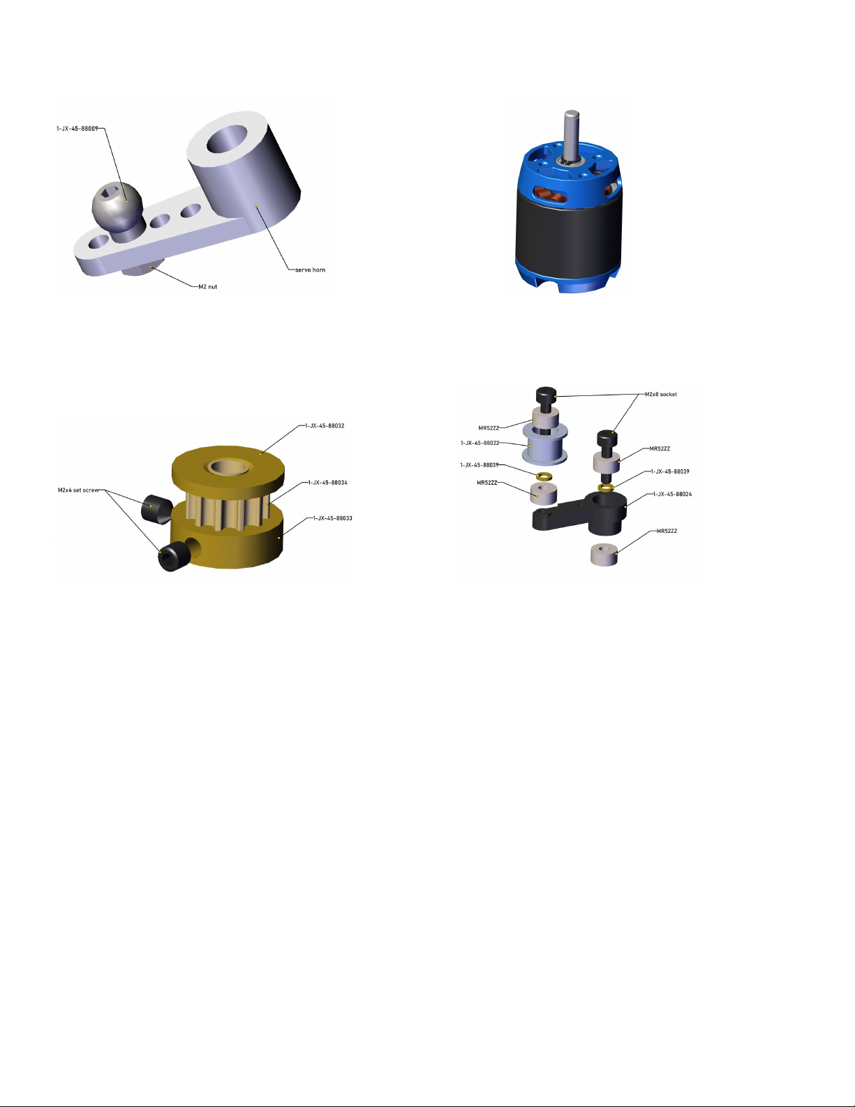
HSM-470-SP023 HSM-470-SP027
HSM-470-SP032 HSM-470-SP033
© 2024 Roban All Rights Reserved. 51
Page 52
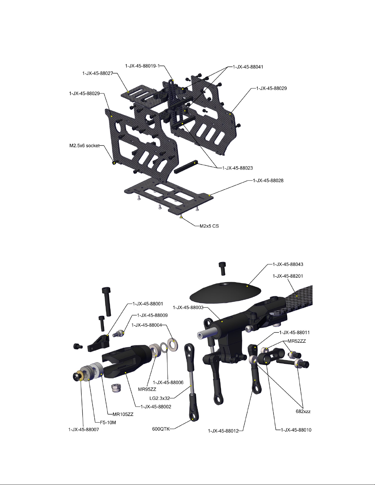
Appendix C. Explosion drawings
Page 53
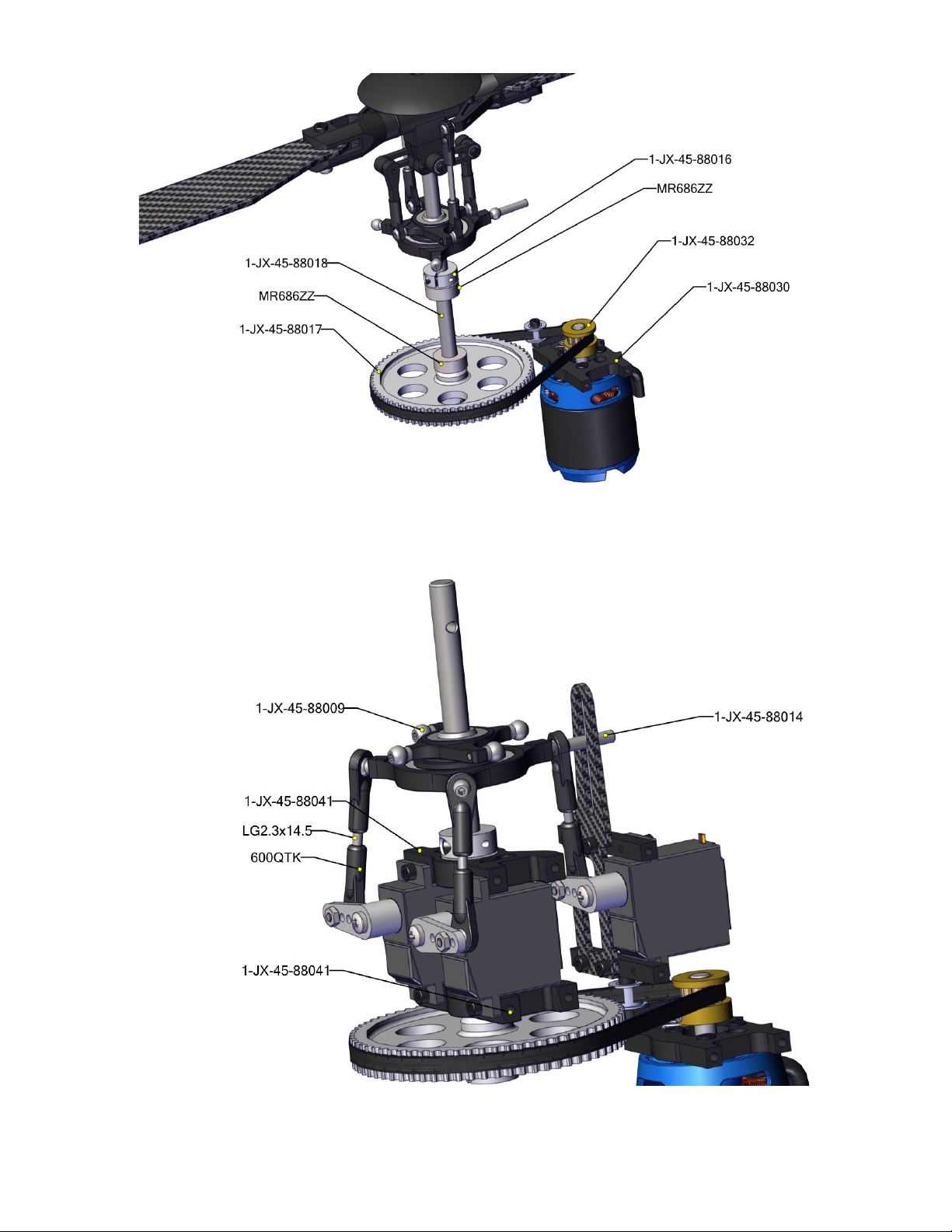
© 2024 Roban All Rights Reserved. 53
Page 54
The end.
 Loading...