

Page 1
User Manual
Before operating this unit, please read the user manual completely and keep it. If the manual is lost,
you can send e-mail to [email protected], request for an electronic manual.
WQP14-W652S
Dishwasher
Page 2

Contents
Introduction . . . . . . . . . . . . . . . . . . . . . . . . . . . . . . . . . . . . . . . . . . . . . . . . . . . . . . . . . . . . . . . . . . . . . . . . . . . . . . . . . . . . . . . . . 3
IMPORTANT SAFETY INSTRUCTIONS . . . . . . . . . . . . . . . . . . . . . . . . . . . . . . . . . . . . . . . . . . . . . . . . . . . . . . . . . . . . . . . . . . 3
BEFORE YOU BEGIN . . . . . . . . . . . . . . . . . . . . . . . . . . . . . . . . . . . . . . . . . . . . . . . . . . . . . . . . . . . . . . . . . . . . . . . . . . . . . . . . . . 3
Preparing to install your dishwasher . . . . . . . . . . . . . . . . . . . . . . . . . . . . . . . . . . . . . . . . . . . . . . . . . . . . . . . . . . . . . . . . . . 4
Enclosure requirements . . . . . . . . . . . . . . . . . . . . . . . . . . . . . . . . . . . . . . . . . . . . . . . . . . . . . . . . . . . . . . . . . . . . . . . . . . . . . . . . . . . . . . . . . . 5
Drain requirements . . . . . . . . . . . . . . . . . . . . . . . . . . . . . . . . . . . . . . . . . . . . . . . . . . . . . . . . . . . . . . . . . . . . . . . . . . . . . . . . . . . . . . . . . . . . . . 6
Drain preparation . . . . . . . . . . . . . . . . . . . . . . . . . . . . . . . . . . . . . . . . . . . . . . . . . . . . . . . . . . . . . . . . . . . . . . . . . . . . . . . . . . . . . . . . . . . . . . . . 6
Electrical requirements . . . . . . . . . . . . . . . . . . . . . . . . . . . . . . . . . . . . . . . . . . . . . . . . . . . . . . . . . . . . . . . . . . . . . . . . . . . . . . . . . . . . . . . . . . . 7
GROUNDING INSTRUCTIONS . . . . . . . . . . . . . . . . . . . . . . . . . . . . . . . . . . . . . . . . . . . . . . . . . . . . . . . . . . . . . . . . . . . . . . . . . . . . . . . . . . . . . . 7
Cabinet preparation and wire routing . . . . . . . . . . . . . . . . . . . . . . . . . . . . . . . . . . . . . . . . . . . . . . . . . . . . . . . . . . . . . . . . . . . . . . . . . . . . . 8
Preparing the hot water line . . . . . . . . . . . . . . . . . . . . . . . . . . . . . . . . . . . . . . . . . . . . . . . . . . . . . . . . . . . . . . . . . . . . . . . . . . . . . . . . . . . . . . 9
Connecting the water line to the water supply . . . . . . . . . . . . . . . . . . . . . . . . . . . . . . . . . . . . . . . . . . . . . . . . . . . . . . . . . . . . . . . . . . . . 9
Installation instructions . . . . . . . . . . . . . . . . . . . . . . . . . . . . . . . . . . . . . . . . . . . . . . . . . . . . . . . . . . . . . . . . . . . . . . . . . . . . . . 10
Step 1: Check the door balance . . . . . . . . . . . . . . . . . . . . . . . . . . . . . . . . . . . . . . . . . . . . . . . . . . . . . . . . . . . . . . . . . . . . . . . . . . . . . . . . . . 10
Step 2: Adjust the leveling legs . . . . . . . . . . . . . . . . . . . . . . . . . . . . . . . . . . . . . . . . . . . . . . . . . . . . . . . . . . . . . . . . . . . . . . . . . . . . . . . . . . 10
Step 3: Remove the toekick . . . . . . . . . . . . . . . . . . . . . . . . . . . . . . . . . . . . . . . . . . . . . . . . . . . . . . . . . . . . . . . . . . . . . . . . . . . . . . . . . . . . . . 11
Step 4: Install to power . . . . . . . . . . . . . . . . . . . . . . . . . . . . . . . . . . . . . . . . . . . . . . . . . . . . . . . . . . . . . . . . . . . . . . . . . . . . . . . . . . . . . . . . . . 11
Step 5: Install the 90° water supply elbow . . . . . . . . . . . . . . . . . . . . . . . . . . . . . . . . . . . . . . . . . . . . . . . . . . . . . . . . . . . . . . . . . . . . . . . . 13
Step 6: Install the drain hose . . . . . . . . . . . . . . . . . . . . . . . . . . . . . . . . . . . . . . . . . . . . . . . . . . . . . . . . . . . . . . . . . . . . . . . . . . . . . . . . . . . . . 14
Step 7: Inserting the drain hose through the cabinet . . . . . . . . . . . . . . . . . . . . . . . . . . . . . . . . . . . . . . . . . . . . . . . . . . . . . . . . . . . . . . 15
Step 8: Slide the dishwasher partially into the cabinet . . . . . . . . . . . . . . . . . . . . . . . . . . . . . . . . . . . . . . . . . . . . . . . . . . . . . . . . . . . . 15
Step 9: Position the dishwasher under the countertop . . . . . . . . . . . . . . . . . . . . . . . . . . . . . . . . . . . . . . . . . . . . . . . . . . . . . . . . . . . . 16
Step 10: Level the dishwasher . . . . . . . . . . . . . . . . . . . . . . . . . . . . . . . . . . . . . . . . . . . . . . . . . . . . . . . . . . . . . . . . . . . . . . . . . . . . . . . . . . . 16
Step 11: Securing the dishwasher to the countertop . . . . . . . . . . . . . . . . . . . . . . . . . . . . . . . . . . . . . . . . . . . . . . . . . . . . . . . . . . . . . . 17
Step 12: Connecting the water supply line . . . . . . . . . . . . . . . . . . . . . . . . . . . . . . . . . . . . . . . . . . . . . . . . . . . . . . . . . . . . . . . . . . . . . . . 19
Step 13: Connecting the drain hose . . . . . . . . . . . . . . . . . . . . . . . . . . . . . . . . . . . . . . . . . . . . . . . . . . . . . . . . . . . . . . . . . . . . . . . . . . . . . . 19
Step 15: Performing a pre-test check . . . . . . . . . . . . . . . . . . . . . . . . . . . . . . . . . . . . . . . . . . . . . . . . . . . . . . . . . . . . . . . . . . . . . . . . . . . . . 21
Step 16: Wet testing the dishwasher . . . . . . . . . . . . . . . . . . . . . . . . . . . . . . . . . . . . . . . . . . . . . . . . . . . . . . . . . . . . . . . . . . . . . . . . . . . . . 22
Step 17: Replacing the toekick . . . . . . . . . . . . . . . . . . . . . . . . . . . . . . . . . . . . . . . . . . . . . . . . . . . . . . . . . . . . . . . . . . . . . . . . . . . . . . . . . . . 22
2
Page 3
Top Control Dishwasher
Introduction
C hase - lit nia pr o
or
relia
This installation w ho o washer
o e e
IMPORTANT SAFETY INSTRUCTIONS
CAUTION
RISK OF ELECTRIC SHOCK
DO NOT OPEN
This at olta o
esent wi ator
WQP14-W652S
Dishwasher
epresents the stat
This ates that there ar tant oper
r erator
tions in the liter
BEFORE YOU BEGIN
these i tions tel e
IMPORTANT
• er
• Note to Installer e to e these instr o s a tor s
• Note to Consumer the tions w User Guide o e r ere e
• Skill Level n ishwasher re es ills Proper installation is the
responsibility of the installer. Product failure due to improper installation is not covered under the appliance
warranty.
• Completion Time
e e ir e
se
IMPORTANT
• T wash e installe o e re is re
• re e washer te
contact your dealer.
FOR YOUR SAFETY
e all W wn tions While per installations
es et wor
Warning
T wa o heat the water To a a ser t
hea en th washe
WARNING: To r e e that the ishwasher is
3
Page 4
Dishwasher
READ CAREFULLY.
KEEP THESE INSTRUCTIONS.
If you have an installation problem, contact your dealer or installer. You are responsible for providing adequate electrical,
exhausting, and other connecting facilities.
Preparing to install your dishwasher
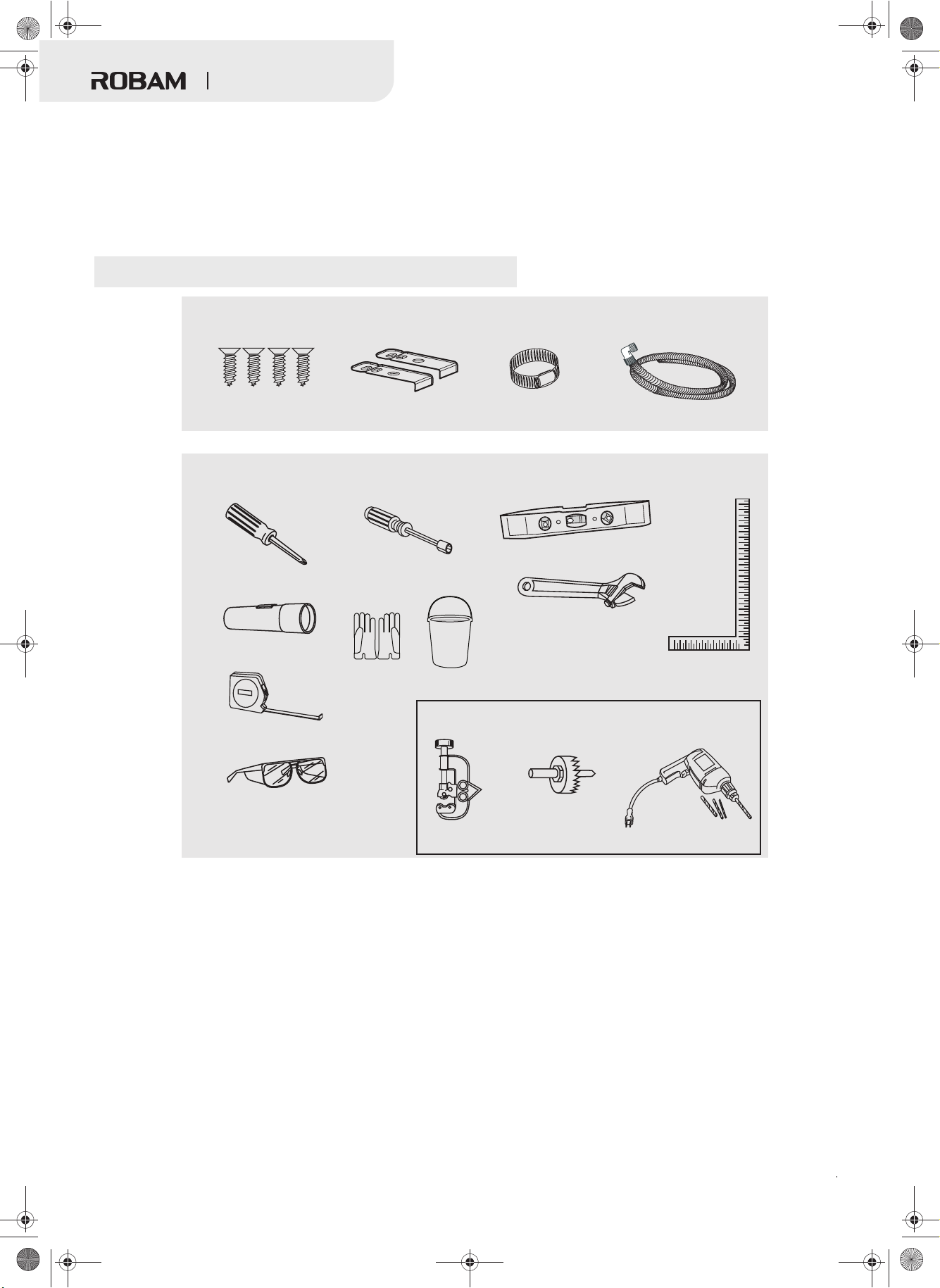
Parts supplied:
Wood screws (4)
Tools needed:
Phillips screwdriver
Flashlight
Measuring tape
Safety glasses
Top mounting clips (2)
1/4 in. and 5/16 in.
Nut driver
Gloves
Bucket
Tubing cutter
Hose clamp
Level
Adjustable wrench
New installations only
Hole saw
set
Drain hose
Carpenters
square
Drill and bits
4
Page 5
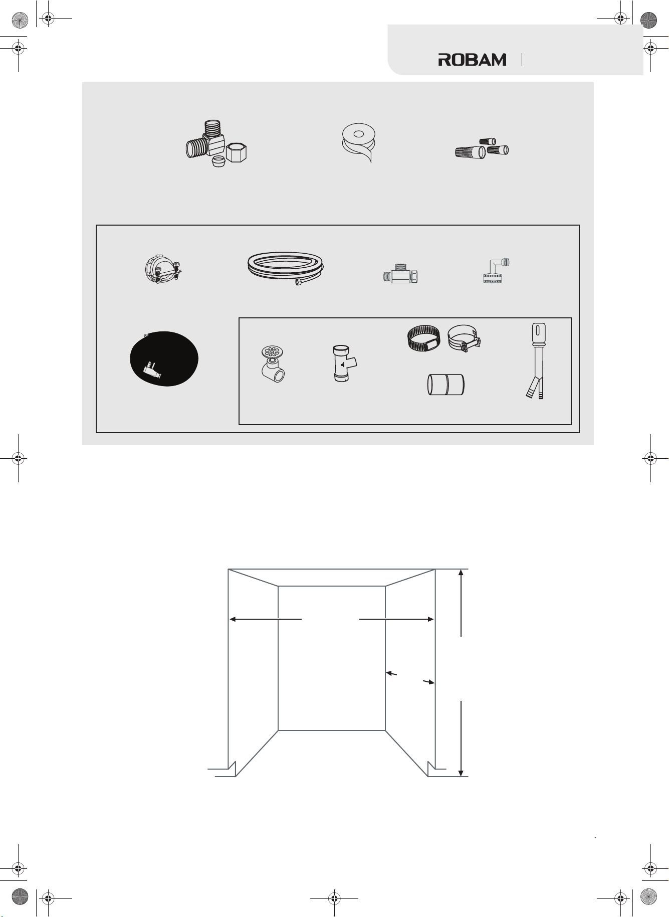
Materials needed (kit purchased separately):
Dishwasher
90° Elbow, ferrule and compression nut. (3/8
NPT external thread on one end. Other end
sized to fit water supply line
New installations only
Strain relief (for
electrical
connections)
Electrical cable or power
cord (See Electrical
Requirements section)
Hot water line (min.
3/8 in. copper) kit
Not included in kit
Hand shut-off
valve
Teflon thread
seal tape
“T” connection
Screw-type hose clamps
Waste tee for
house plumbing
(if applicable)
Three wire nuts (UL listed)
(two included in kit)
Gardenhose
connection
Coupler for extending
drain line (if applicable)
Air gap (if
required)
Enclosure requirements
• The dishwasher must be installed so that the drain hose is no more than 10 feet (3.01 m) in length, for proper drainage.
• This dishwasher is designed to be enclosed on the top and on both sides by a standard residential kitchen cabinet unit.
• The installation enclosure must be clean and free of any obstructions.
• The enclosure must be at least 24 inches (61 cm) wide, 24 inches (61 cm) deep, and 34 inches (86.4 cm) high.
• For the front door of the dishwasher to be flush with the front edge of the counter top, the counter top must be 25
inches (63.5 cm) deep.
24” (61 cm)
min.
24” (61 cm)
min.
min.
34” (86.4cm)
5
Page 6
Dishwasher
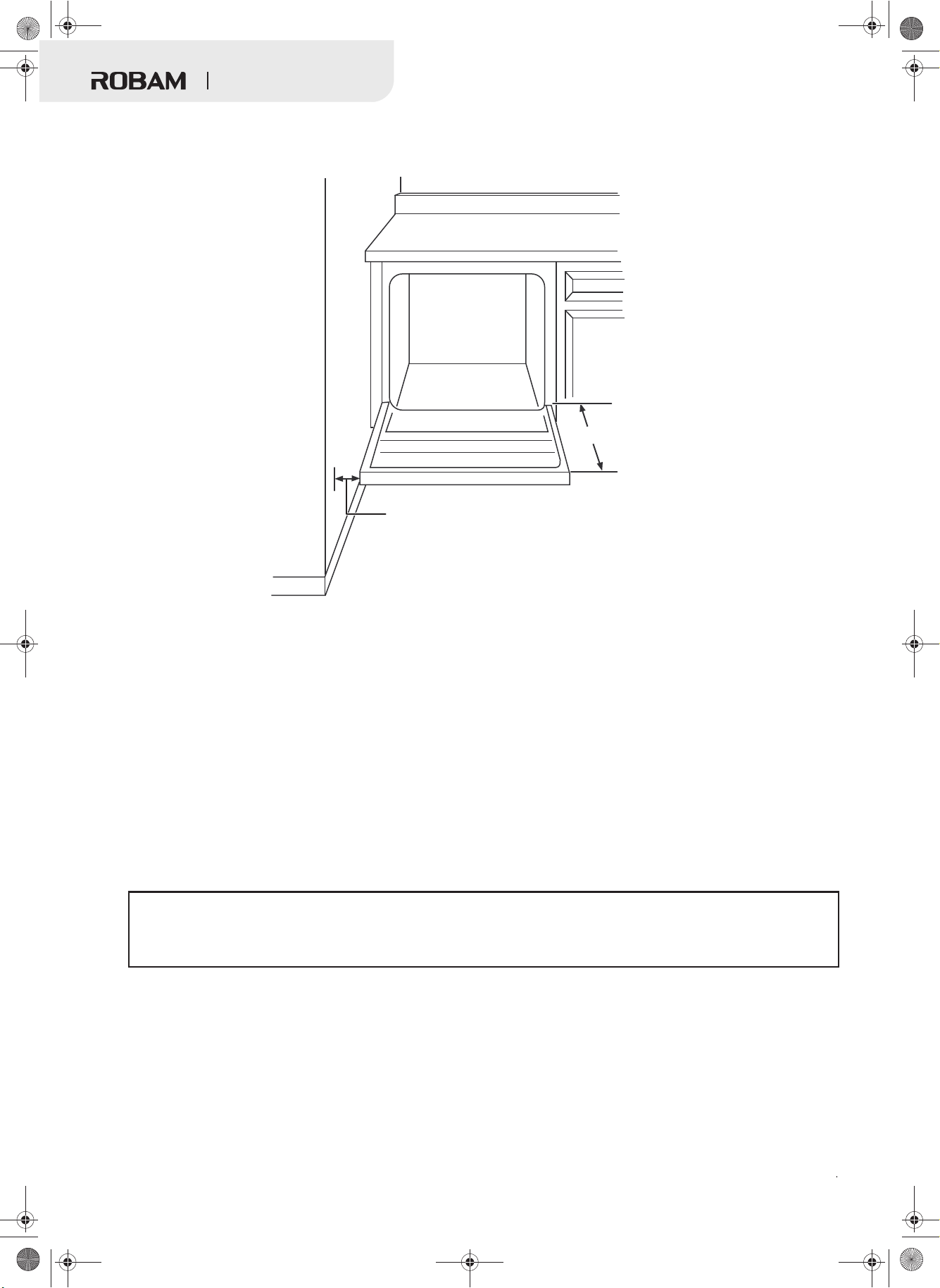
If installing into a corner, allow 2 in. (5.08 cm) min. clearance between dishwasher and adjacent cabinet, wall, or other
appliances. Allow 25.63 in. (65.1 cm) min. clearance from the front of the dishwasher for opening the door.
Countertop
Dishwasher
25.63”(65.1 cm)
Clearance for door opening
2” (5.08 cm) min.
Drain requirements
• Follow all local codes and ordinances.
• Do not exceed 10 ft. (3.01 m) of drain hose.
• Do not connect the drain lines from other devices to the dishwasher drain hose.
• The dishwasher must be connected to a waste line with an air gap (not provided) or a 32 in. (81.28 cm) high (min.) drain
loop, depending on local codes and ordinances, to prevent back flow into the dishwasher.
• An air gap must be used if the waste tee or garbage disposal connection is less than 18 in. (45.72 cm) above the floor, to
prevent siphoning.
Drain preparation
The type of drain installation required depends on the answers to the following questions:
• Do local codes or ordinances require an air gap?
• Will the waste tee or garbage disposal connection be less than 18 in. (45.72 cm) above the floor?
• Will installation have a drain loop less than 32 in. (81.28 cm) above the floor?
If the answer to ANY of these questions is YES, Method 1 MUST be used. Otherwise, either Method 1 or
Method 2 may be used.
Caution:
• An air gap MUST BE USED if the drain hose is connected to a waste tee or garbage disposal lower than 18 in. (45.72 cm) above the
floor.
• Failure to provide the proper drain connection height with an air gap or 32 in. (81.28 cm) (min.) high drain loop will result in
improper draining of the dishwasher.
Install the waste tee or garbage disposal connection and air gap according to manufacturer’s instructions.
6
Page 7
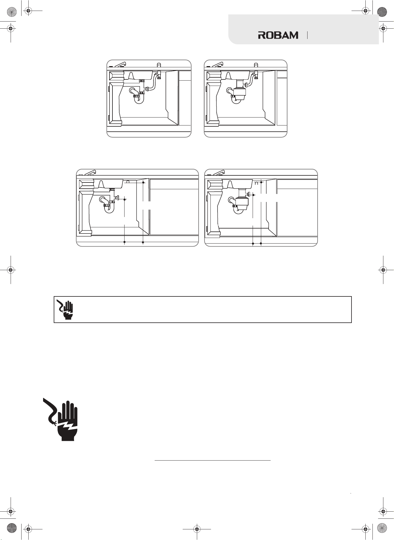
Method 1 - Air gap with a waste tee or garbage disposal connection
Method 2 - High drain with a waste tee or garbage disposal connection
You must provide a method to attach the drain hose to the underside of the countertop.
32 in. (81.28 cm) (min.)
Dishwasher
32 in. (81.28 cm) (min.)
18 in. (45.72 cm)
18 in. (45.72 cm)
Electrical requirements
• This appliance must be supplied with 120V, 60 Hz, and it must be connected to its own, properly grounded branch
circuit that is protected by a 15 or 20 ampere circuit breaker or time delay fuse.
• Wiring must be two wire with ground.
• If the electrical supply does not meet the above requirements, call a licensed electrician before proceeding.
Warning:
cord or adapter plug with this appliance.
Remove the house fuse or open the circuit breaker before beginning the installation. Do not use an extension
GROUNDING INSTRUCTIONS
Grounding Instructions – Cable Direct
This appliance must be connected to a grounded metal, permanent wiring system, or an equipment grounding conductor
must be run with the circuit conductors and be connected to the equipment grounding terminal or lead on the appliance.
Grounding Instructions – Power Cord Models
This appliance must be grounded. In the event of a malfunction or breakdown, grounding will reduce the risk of electrical
shock by providing a path of least resistance for electric current. The plug must be plugged into an appropriate outlet that
is installed and grounded in accordance with local codes and ordinances.
WARNING
The improper connection of the equipment grounding conductor can result in a risk of electric shock. Check
with a qualified electrician or service representative if you are in doubt that the appliance is properly
grounded.
Direct Wire Method
• The cable must be routed as shown in Cabinet preparation and wire routing
(60.96 cm) from the rear wall.
• Use flexible, armored, or nonmetallic sheathed, copper wire with grounding wire that meets the wiring requirements
for your home and local codes and ordinances.
• Use a UL Listed/CSA Approved strain relief.
on page 8, and extend a minimum of 24 in.
7
Page 8
Dishwasher
Power Cord Method
• Install a 3-prong grounding type receptacle. The wall outlet can be installed in a cabinet or on a wall adjacent to the
undercounter space in which the dishwasher is to be installed.
• Use power cord kit (part number 5304504505) under Smart Choice brand marked with Dishwasher Install Kit With
Power Cord, available for purchase from an authorized store. The power cord and connections must comply with local
codes and ordinances.
• The recommended power cord length is 54 in. (1.4 m) min. and 64 in. (1.6 m) max.
Cabinet preparation and wire routing
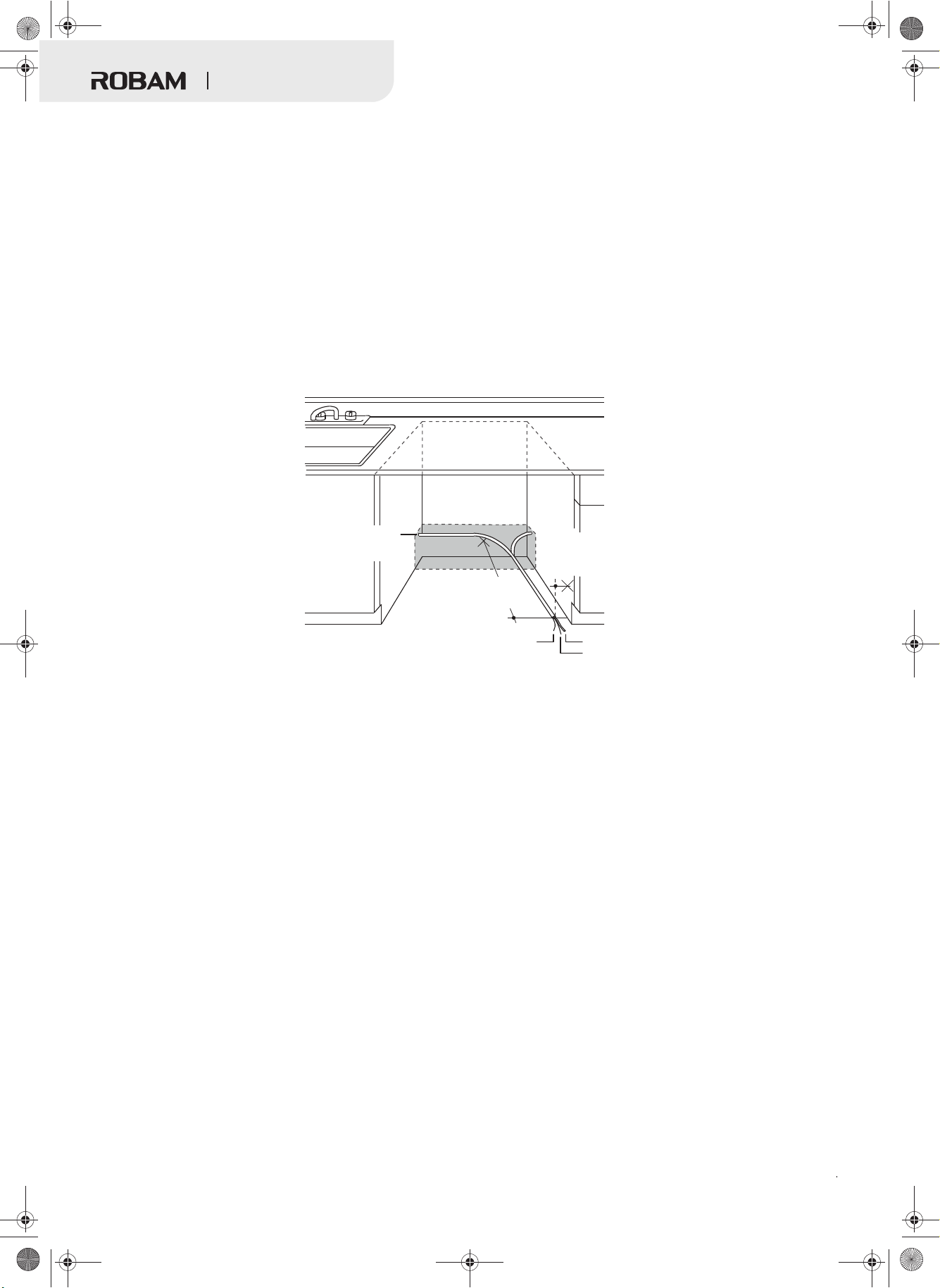
• The wiring may enter the opening from either side, the rear, or the floor within the shaded area.
• The electrical connection is on the front right of the dishwasher.
• Drill a 1.5 in. (3.81 cm) maximum diameter hole to run the electrical cable through the wall of the cabinet.
• The hole must be free of sharp edges. If the cabinet wall is metal, the hole edge must be covered with a bushing or
rubber grommet.
• Cable direct connections may pass through the same hole as the drain hose and hot water line, but power cords with
plugs must pass through a separate hole.
1.5 in. (3.81 cm)
diameter hole (max.)
24 in. (60.96 cm)
from wall
Ground
2.5–3.5 in. (6.5–9.0 cm)
from cabinet
White
Black
8
Page 9
Dishwasher
Preparing the hot water line
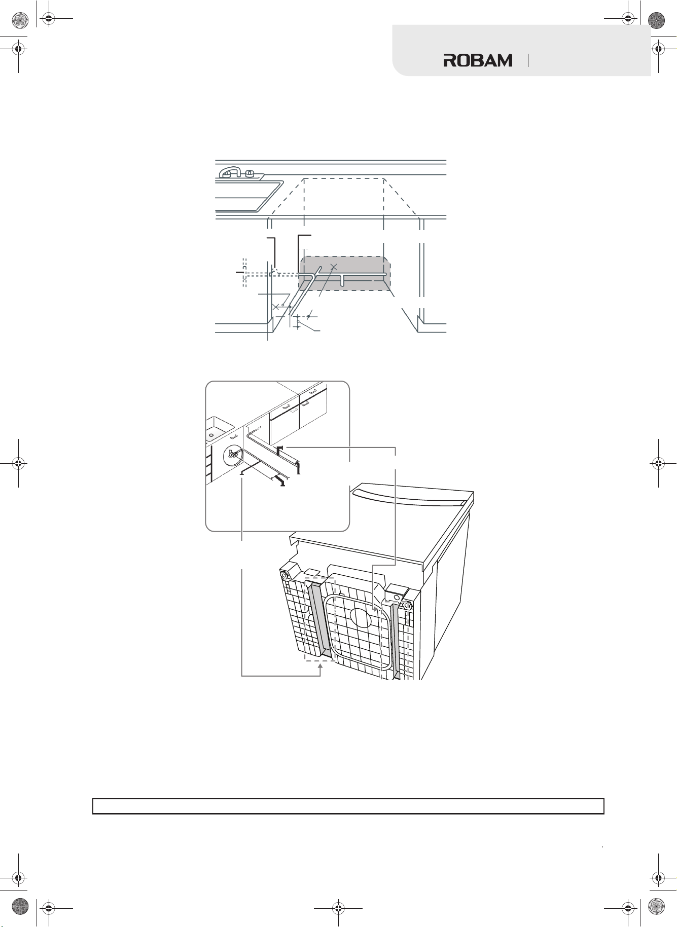
• The water connection is on the left side of dishwasher.
• The hot water line may enter the opening from either side, the rear, or the floor within the shaded area.
• The hot water line may pass through the same hole as the electrical and drain hose. Or, you can drill an additional 1.5 in.
(3.81 cm) maximum diameter hole for the hot water line.
• If a power cord with a plug is used, the hot water line may not pass through the same hole as the power cord.
Shut-off valve
Hot
5.3–7.3 in.
(13.5–18.5 cm)
from cabinet
Cabinet face
2.5–3.5 in.
(6.5–9.0 cm)
5.3–7.3 in.
(13.5–18.5 cm)
from cabinet
1.5 in. (3.81 cm) diameter hole (max.)
18 in. (45.72 cm) from wall
3 in. (7.62 cm)
from floor
Power cable
Water supply
line
Connecting the water line to the water supply
1 Turn off the water supply.
2 Install a hand shut-off valve in an accessible location, such as under the sink. This is optional, but strongly
recommended, and may be required by local codes.
3 Install the hot water inlet line, using at least 3/8 in. O.D. copper tubing. Route the line as shown in the figure above and
extend it forward at least 18 in. (45.72 cm) from the rear wall of the enclosure.
4 Adjust the water heater to a temperature of 120° F to 150° F (49° C to 65° C).
5 Flush the water line to clean out any debris.
Note:
The hot water pressure must be between 20 and 120 psi (138 and 827 kPa).
9
Page 10
Dishwasher
Installation instructions
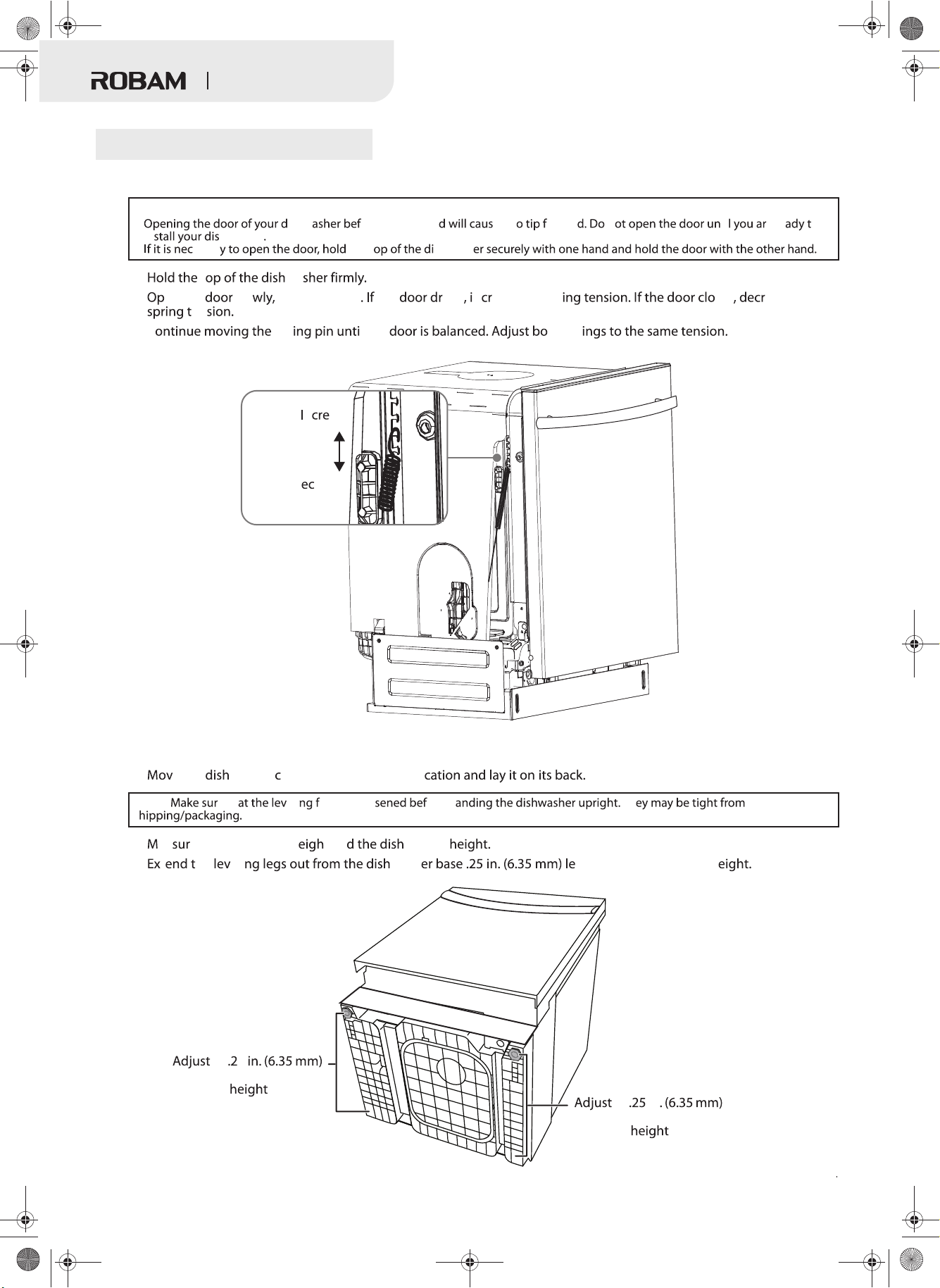
Step 1: Check the door balance
Caution:
• ishw ore it is installe e it t orwar n ti e re o
in hwasher
• essar the t shwash
1 t wa
2 en the slo then release it the ops n ease the spr ses ease the
en
3 C spr l the th spr
n ase
D rease
Step 2: Adjust the leveling legs
1 e the washer lose to the installation lo
Note:
s
2 ea e the installation h t an washer
3 t he eli wash ss than the installation h
e th eli eet are loo ore st Th
to 5
less than the installation
to in
less than the installation
10
Page 11
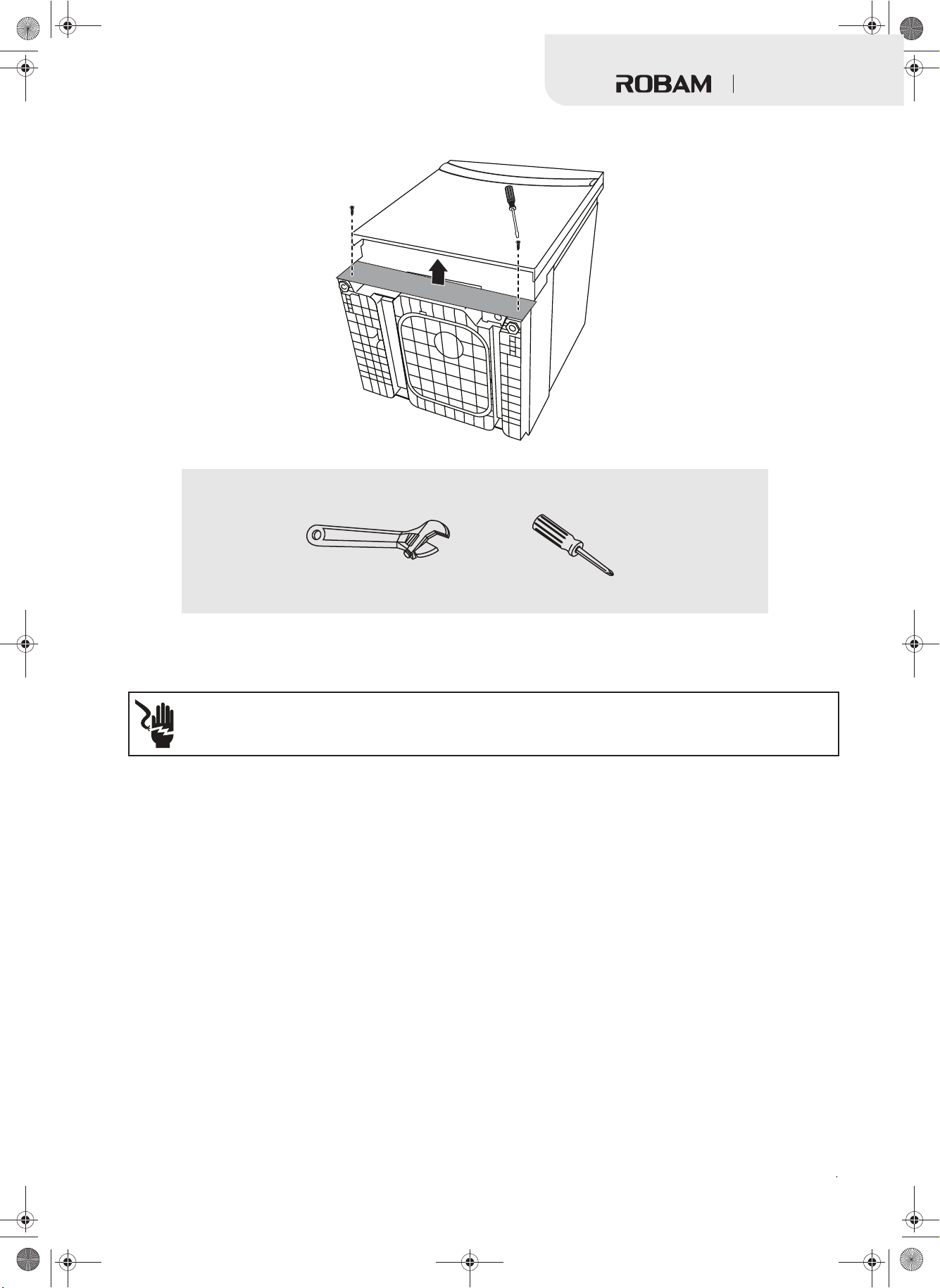
Step 3: Remove the toekick
• Remove the two toekick screws with a Phillips screwdriver, then remove the toekick.
Dishwasher
You’ll need:
Adjustable wrench
Step 4: Install to power
Turn off the electricity to the dishwasher’s electrical circuit.
Make sure that the electrical power is turned off at the source.
Warning:
•If your house wiring is not 2-wire with a ground, a ground must be provided by the installer.
•If your house wiring is aluminum, be sure to use cUL/UL Listed anti-oxidant compound and aluminum-to-copper
connectors.
Power cord
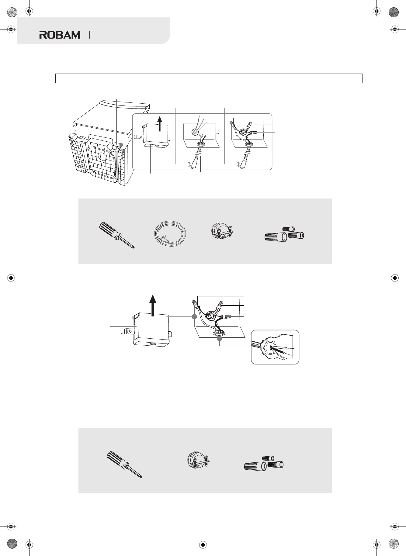
1 Remove the junction box cover on the front right of the dishwasher.
2 Make sure that the junction box’s electrical wires are pulled inside of the junction box.
3 Remove the lock nut from the strain relief, then push the strain relief into the round opening of the junction box.
4 Install the lock nut on the strain relief from inside the junction box.
5 Insert the ends of the power cord’s electrical wires into the junction box through the strain relief.
6 Connect the incoming white (or ribbed) wire to the dishwasher’s white wire, the black (or smooth) wire to the
dishwasher’s black wire, and the ground wire to the dishwasher’s green wire. Use cUL/UL listed wire nuts of the
appropriate size.
7 Tighten the strain relief screws and lock nut to stabilize the power cord’s electrical wires, then make sure that all of the
connections are secure.
Phillips screwdriver
11
Page 12
Dishwasher
8 Replace the junction box cover on the right front of the dishwasher. Be sure that the wires are not pinched under the
cover.
Note: If you have trouble replacing the junction box cover, loosen the screws on the strain relief.
Junction box
Ground to green
White to white
Black to black
Junction
box
Power cord
You’ll need:
Phillips screwdriver
Direct wiring
1 Remove the junction box cover from the power supply junction box on the wall.
Junction box
Power cord
Strain relief (for
electrical connections)
Three wire nuts
(UL listed)
Ground to green
White to white
Black to black
Insert wires through strain relief fitting and tighten
2 Locate the three dishwasher wires, (white, black, and green) with stripped ends, then insert the dishwasher wires
through the small hole in the junction box.
3 Secure the house wiring to the bottom of the junction box with a strain relief fitting.
4 Use wire nuts to connect incoming ground to green, white to white, and black to black.
5 Replace the junction box cover. Make sure that no wires are pinched under the cover.
You’ll need:
Phillips screwdriver
Strain relief (for
electrical connections)
Three wire nuts
(UL listed)
12
Page 13
Dishwasher
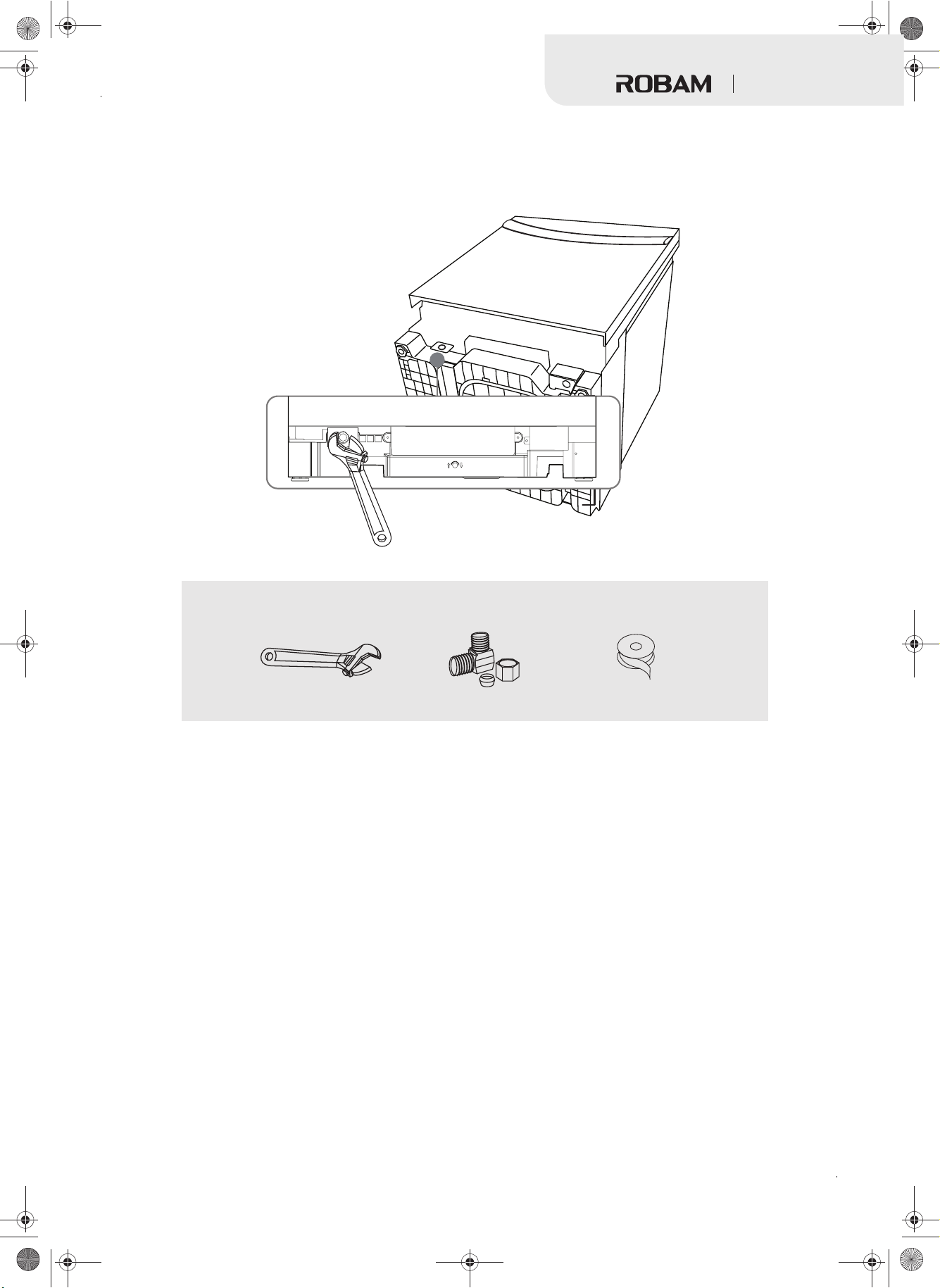
Step 5: Install the 90° water supply elbow
1 Wrap the male thread of the 90° elbow with Teflon thread seal tape twice. Do not use plumber's putty.
2 Install the 90° elbow onto the water valve. Do not overtighten the 90° elbow. The water valve bracket could bend or the
water valve fitting could break.
3 Position the end of the elbow to face the floor when the dishwasher is upright.
You’ll need:
Adjustable wrench
90° elbow
Teflon thread
seal tape
13
Page 14
Dishwasher
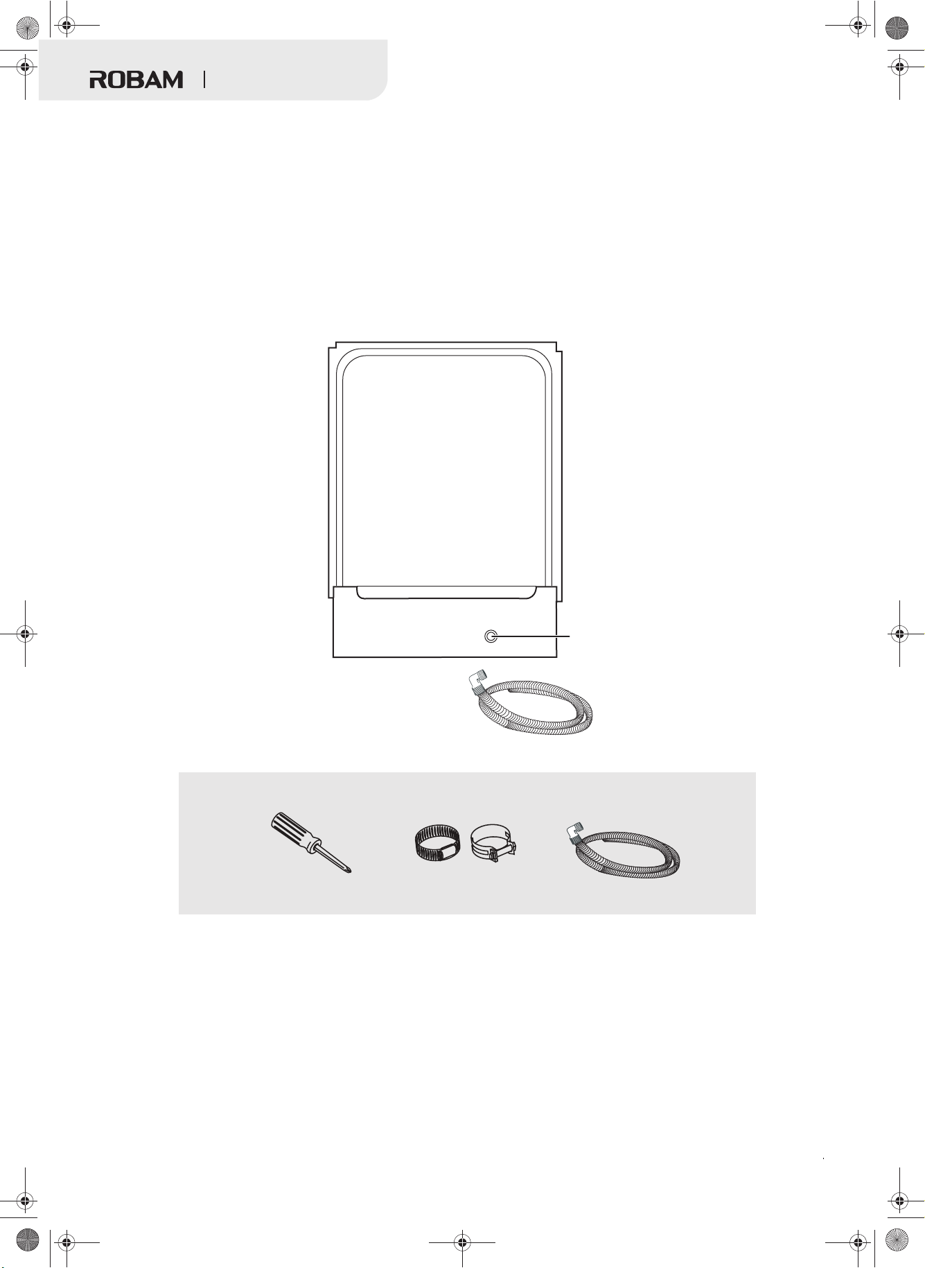
Step 6: Install the drain hose
1 Make sure that the leveling feet are loosened before standing the dishwasher upright. They may be tight from
shipping/packaging.
2 Turn the dishwasher upright.
3 Slide a screw-type hose clamp onto the right-angled end of the drain hose.
4 Install the drain hose to the dishwasher drain outlet on the back of the dishwasher, then tighten the screw-type hose
clamp.
Back of dishwasher
You’ll need:
Phillips screwdriver
Screw-type
hose clamps
Drain hose installation hole
Drain hose
14
Page 15
Dishwasher
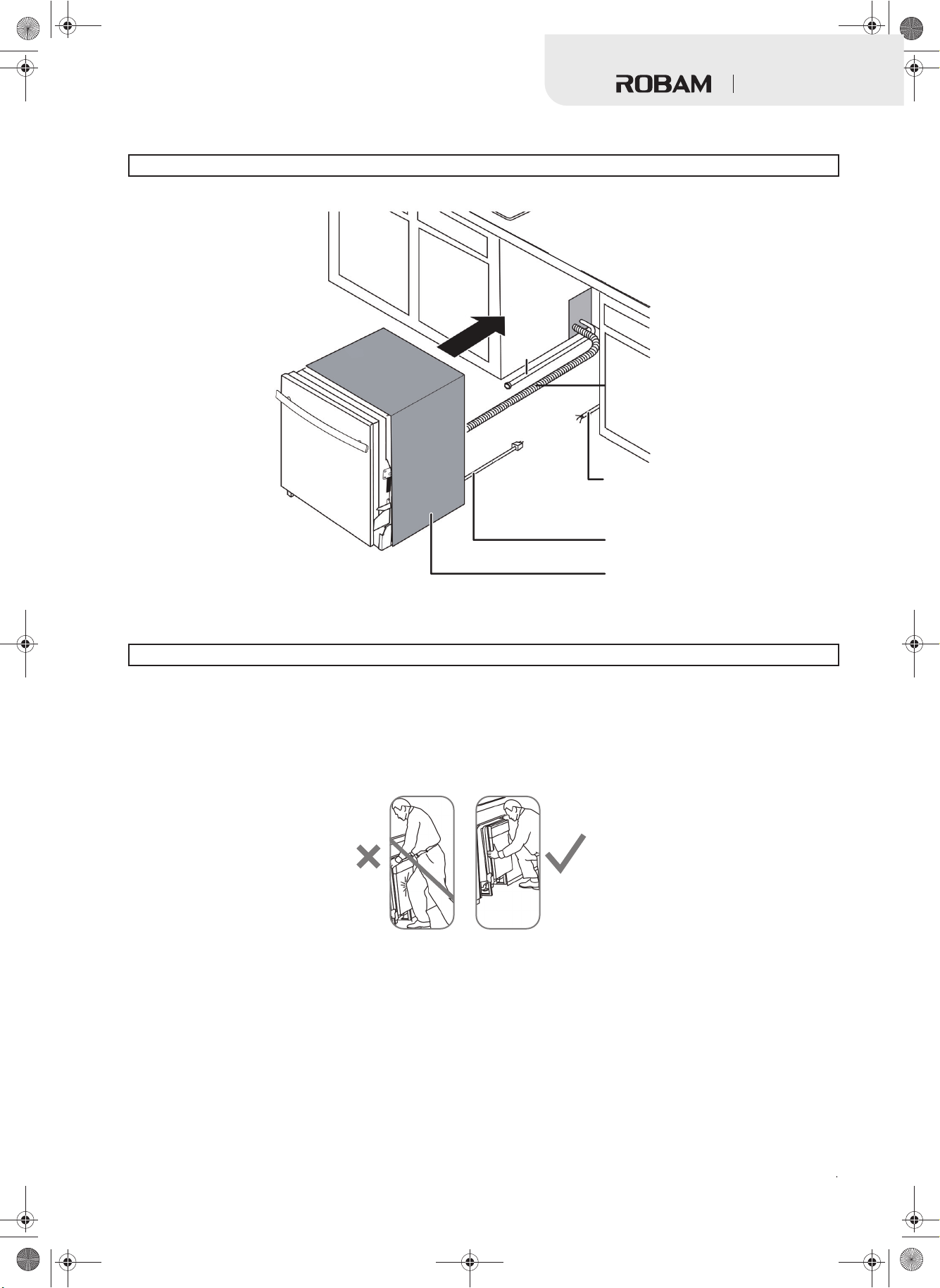
Step 7: Inserting the drain hose through the cabinet
• Insert the drain hose into the hole in the cabinet wall. If a power cord is used, guide the end through a separate hole.
Tip: Position the water line and house wiring on the floor to avoid interfering with the base of the dishwasher.
Maximum drain hose
length 10 ft. (3.01 m)
Water
line
Drain hose
House wiring
OR
Power cord (if used)
Insulation blanket
Step 8: Slide the dishwasher partially into the cabinet
Caution:
1 Position the dishwasher in front of the opening, then slide the dishwasher into the opening a few inches at a time.
2 Pull the drain hose through the opening under the sink as you proceed. Stop when the dishwasher is a few inches in
3 Make sure that the drain hose is not kinked under the dishwasher and that there is no interference with the water line,
Do not push against the front panel with your knees. Damage will occur.
front of the adjacent cabinetry.
wiring, or any other component.
Do not push against the
front door panel with your
knees. You will damage the
front panel.
15
Page 16
Dishwasher
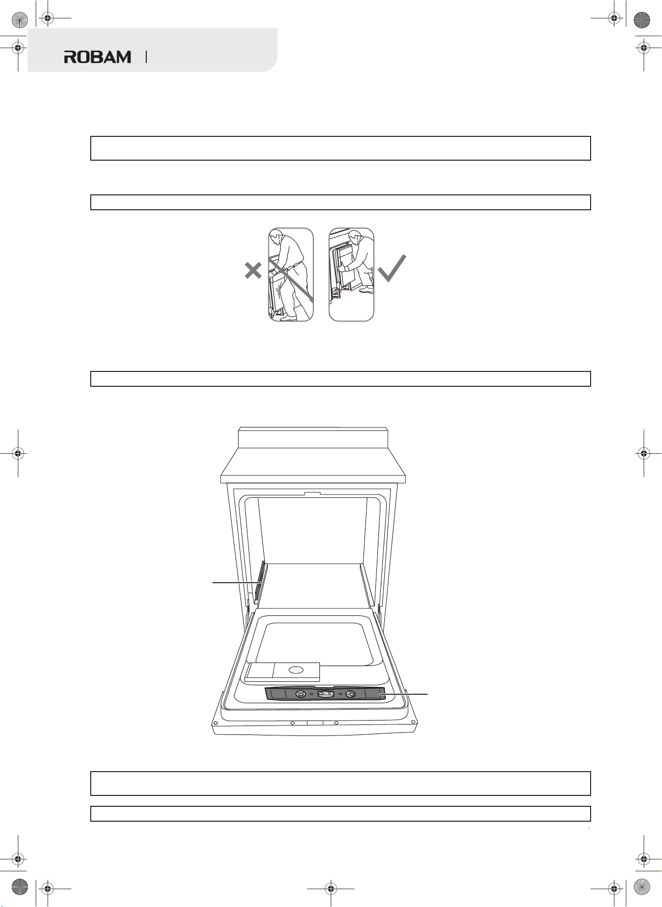
Step 9: Position the dishwasher under the countertop
1 Make sure that the wires are secure under the dishwasher and not pinched or in contact with door springs or other
dishwasher components.
Tip: Check tub insulation blanket, if equipped. It should be positioned so it is not bunched up or interfering with door springs. Check
by opening and closing the door.
2 Push the dishwasher into the cabinet. The front corners of the dishwasher door should be flush with the cabinet doors.
Be careful not to dent the front panel with your knees or damage the countertop or cabinets with dishwasher parts.
Note: You will not have access to the back leveling legs once the dishwasher is put in place.
Do not push against the
front door panel with your
knees. You will damage
the front panel.
Reposition the dishwasher
by grasping both sides with
your hands.
Step 10: Level the dishwasher
IMPORTANT: The dishwasher must be level for proper dish rack operation and wash performance.
1 Open the door, then place a level on the door and on the rack track inside the tub to make sure that the dishwasher is
level.
Check front-to-back level
Check side-to-side level
2 Level the dishwasher by adjusting the four leveling legs individually.
Tip: Pull the lower rack out about halfway. Make sure that the rack does not roll forward or back into the dishwasher. If the rack rolls in
either direction, you must level the dishwasher again.
Note: You may need to pull your dishwasher out of the cabinet if major adjustments to the four leveling legs are required.
16
Page 17
Dishwasher
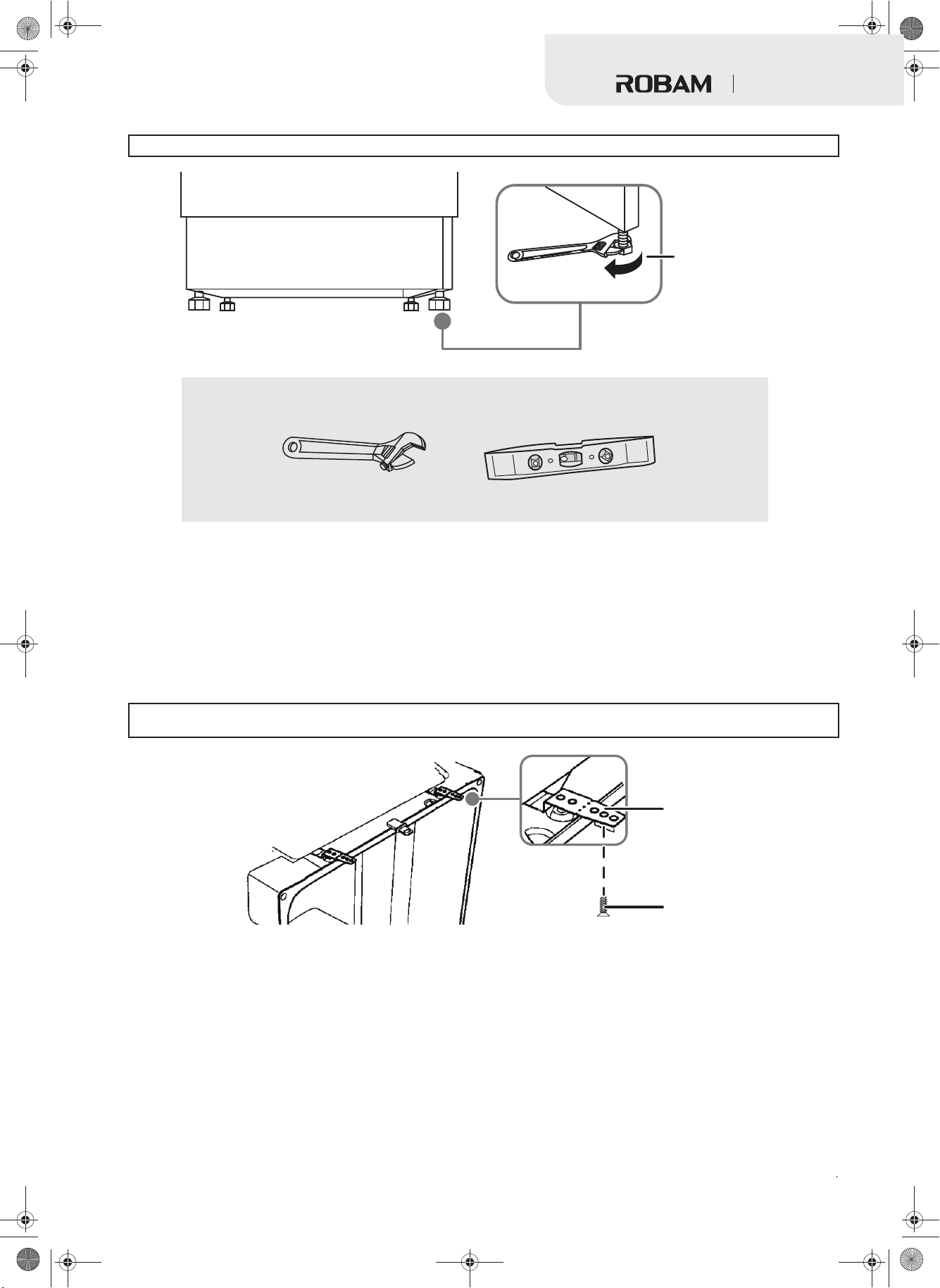
3 If the door hits the tub, the dishwasher is not installed correctly. Adjust the leveling legs to align the door to the tub.
Note:
Keep the dishwasher level.
Turn the legs
to adjust the
level
You’ll need:
Adjustable wrench
Level
Step 11: Securing the dishwasher to the countertop
• For countertops made of wood or materials that won’t be damaged by drilling, use Method 1.
• For countertops made of granite, marble, or other materials that could be damaged by drilling, use Method 2.
• If the gap between the control panel and the cabinet is less than 0.4 in. (10 mm), use Method 2.
Method 1
1 Insert the long top mounting clips into the slot.
2 Bend the brackets to secure them to the dishwasher tub.
3 Secure the dishwasher to the countertop through the holes in the brackets, using the screws provided.
IMPORTANT: Drive the screws straight and flush. Protruding screw heads will scratch the top of the control panel and interfere with
the door closing.
Top mounting
clip
Screw
17
Page 18
Dishwasher
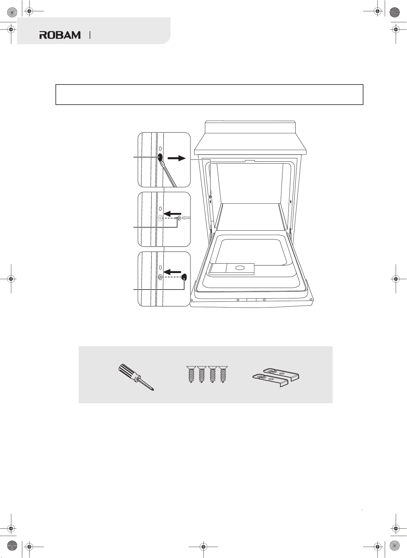
Method 2
1 Remove the plastic tub caps from the inside of the dishwasher tub.
2 Drive a wood screw through the hole in the side of the dishwasher into the cabinet frame.
IMPORTANT: Drive the screws straight and flush. Protruding screw heads will scratch the side if the dishwasher. This method is for
attaching the dishwasher to the side of the cabinet, and it should be done when the countertop is made of granite or other breakable
materials.
3 Reinsert the plastic tub caps.
Plastic
tub cap
Screw
Plastic
tub cap
You’ll need:
Phillips screwdriver
Wood screws (2)
(two for each method)
Top mounting clips (2)
18
Page 19
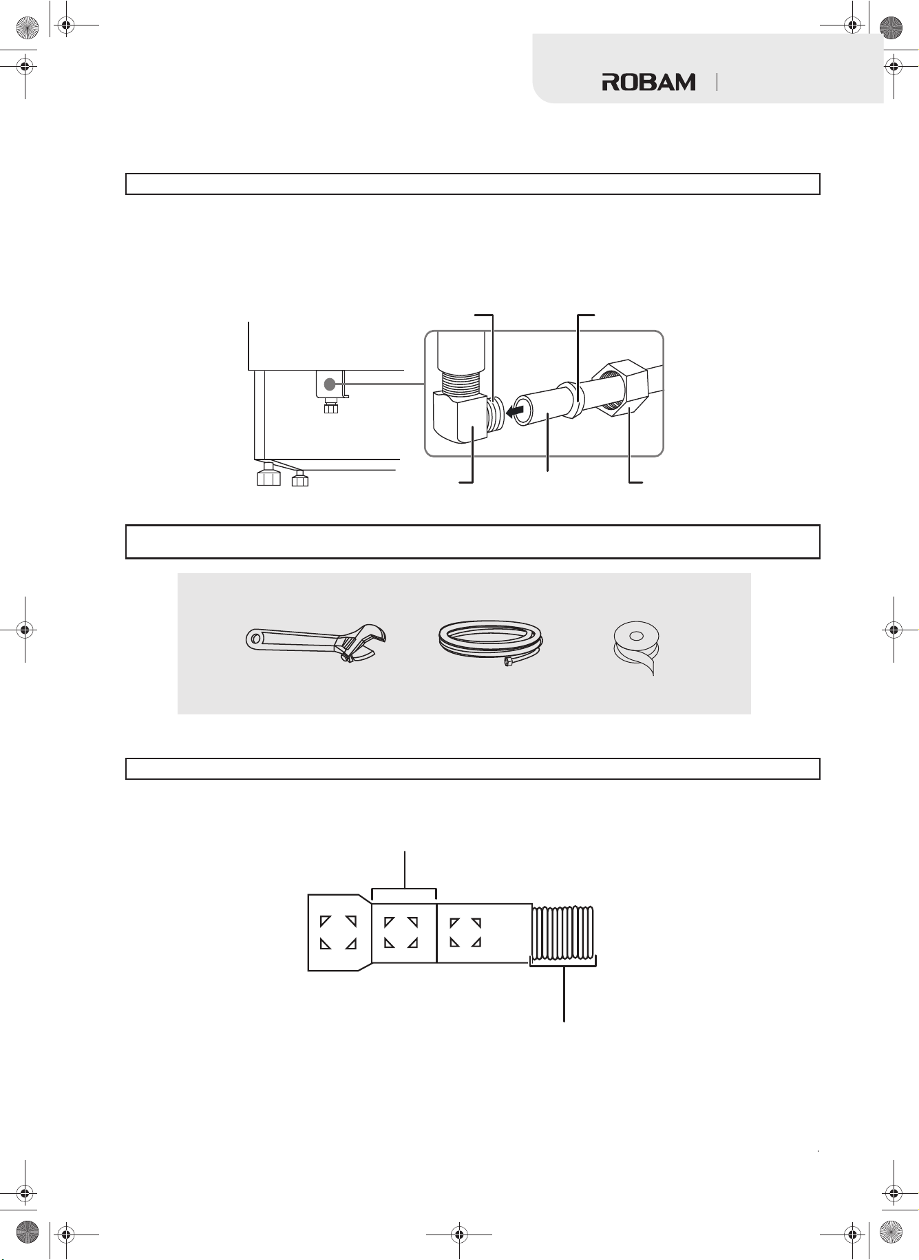
Step 12: Connecting the water supply line
1 Make sure that you wrapped the 90° elbow with Teflon thread seal tape twice.
2 Slide the compression nut, then the ferrule over the end of the water supply line.
Note: If you have a steel-grated line, you do not need a ferrule or compression nut.
3 Insert the water supply line into the 90° elbow.
4 Slide the ferrule against the 90° elbow and secure it with the compression nut.
Back of dishwasher
Dishwasher
Two wraps of Teflon
thread seal tape
90° elbow
IMPORTANT: Make sure that the door spring does not rub or contact the water supply line or drain hose. Test by opening and
closing the door. Reroute the lines if interference occurs.
Water supply line
Ferrule
Compression nut
You’ll need:
Adjustable wrench
Hot water line kit
Teflon thread seal tape
Step 13: Connecting the drain hose
IMPORTANT:
1 Cut on the marked line as required for your installation. The drain hose’s molded end will fit 5/8”, 3/4” or 1" diameter
connections on the air gap, waste tee, or garbage disposal.
Follow all local codes and ordinances.
Cutting lines
IMPORTANT: Do not cut
corrugated portion of hose
19
Page 20
Dishwasher
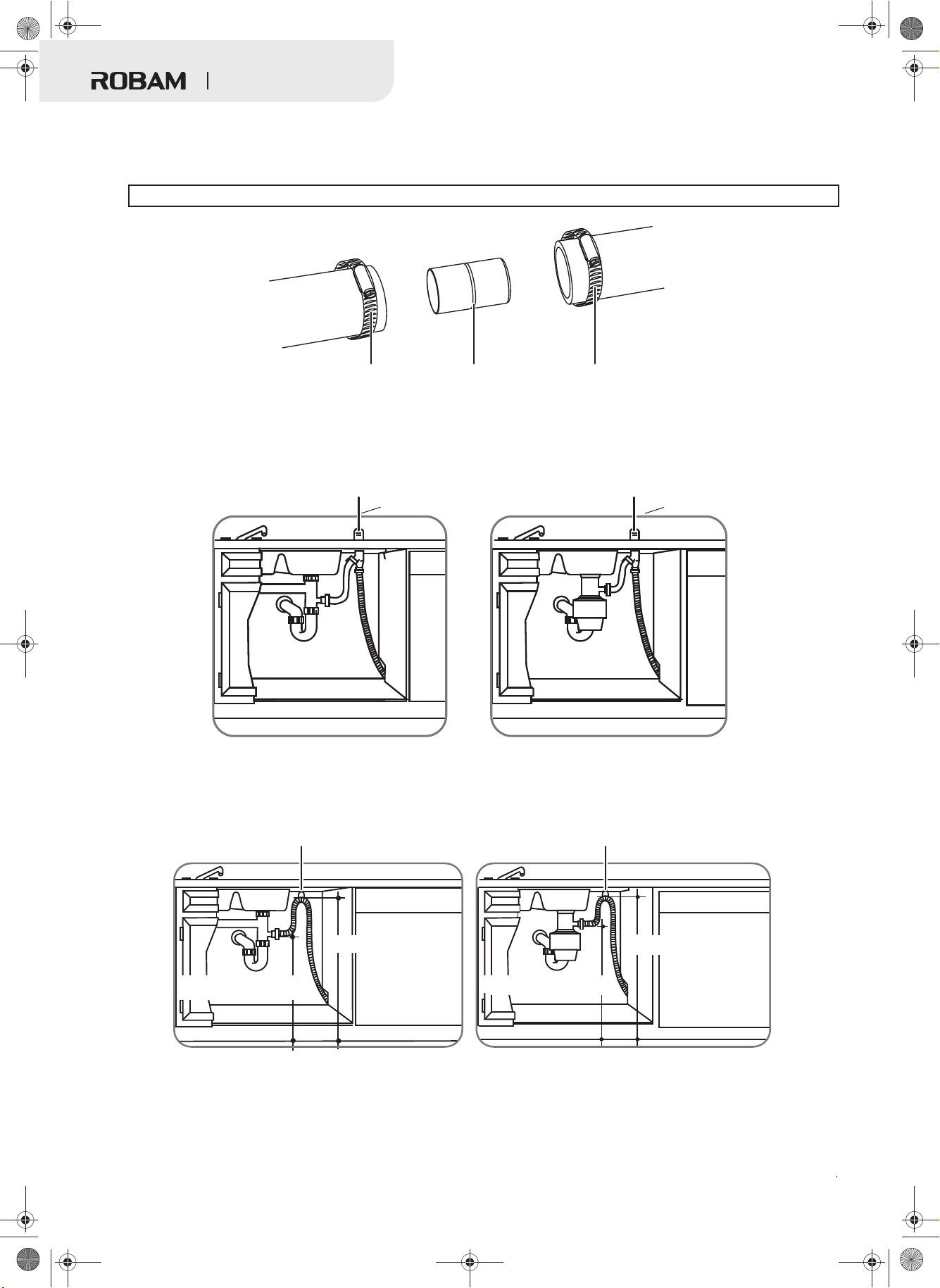
2 If a longer drain hose is required, you can add up to 42" (1.1 m) of length, for a total of 10 ft. (3.01 m) to the factory
installed hose. Use 5/8” or 7/8” inside diameter hose and a coupler to connect the two hose ends. Secure the
connection with screw-type hose clamps.
IMPORTANT: For proper drain operation, the total drain hose length must not exceed 10 ft. (3.01 m).
Screw-type hose clamp
Coupler
Screw-type hose clamp
3 Secure the drain hose to the air gap, waste tee, or garbage disposal with a screw-type clamp, using the appropriate
method below. See “Drain preparation on page 6” on page 6, if you do not know which method to to use.
Method 1 - Air gap to a waste tee or garbage disposal.
AirgapAirgap
Waste tee installation
Garbage disposal installation
Method 2 - High drain loop to a waste tee or garbage disposal
Fasten to the underside of
the countertop
32 in. (81.28 cm) min.
18 in. (45.72 cm) min.
Waste tee installation
20
Fasten to the underside
of the countertop
32 in. (81.28 cm) min.
18 in. (45.72 cm) min.
Garbage disposal installation
Page 21
Dishwasher
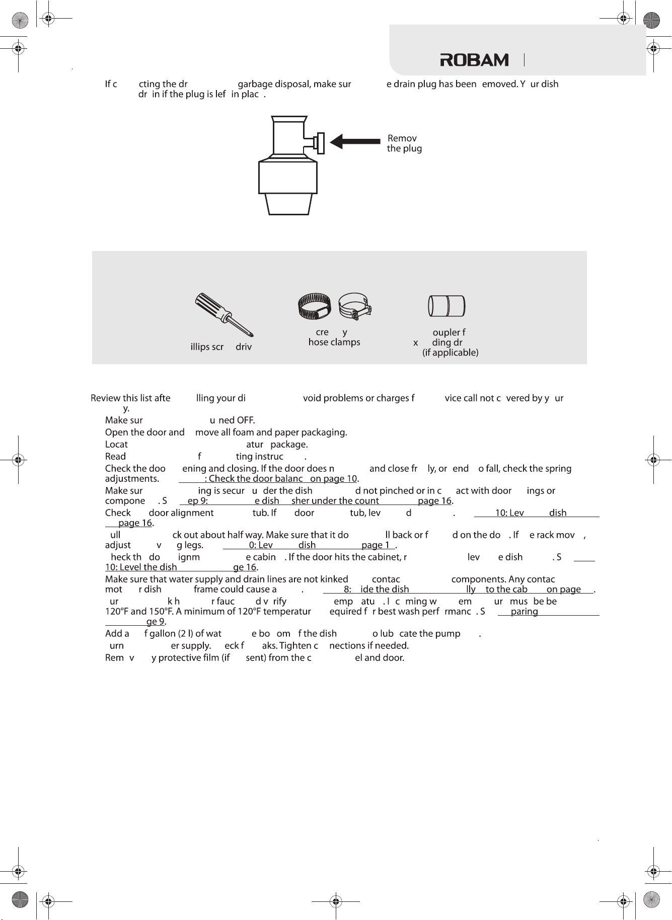
4 onne ain line to a e that th r o washer
will not
a t e
e
You’ll need:
S w-t pe
Ph ew er
C or
e ten ain line
Step 15: Performing a pre-test check
r insta shwasher to a or a ser o o
warrant
• e that power is t r
• re
• e the user manual in the liter e
• the user manual or opera tions
• r op ot open ee t s t
See Step 1 e
• e that the wir e n washer an ont spr other
nts ee St Position th wa ertop
• the with the the hits the el the ishwasher See Step el the washer
on
• P the lower ra es not ro orwar or th es
the le elin See Step 1 el the washer on 6
• C e or al ent with th et eposition or re el th washer ee Step
washer on pa
• or in t with other t with the
or o washer noise See Step Sl washer partia in inet
• T n on the sin ot wate et an e the water t er re n o ater t perat e t tween
e is r o o e ee Pre the hot water
line on pa
• hal er to th tt o washer t ri seal
• T on the wat Ch or le on
• o e an pre ontrol pan
on
15
21
Page 22
Dishwasher
Step 16: Wet testing the dishwasher
1 Turn on the power supply (or plug the power cord into the outlet, if equipped).
2 Turn on your dishwasher (refer to the User Guide for instructions).
3 Close the door, select the Rinse only cycle, and press START/Cancel.
4 Make sure that water enters the dishwasher. If water does not enter the dishwasher, check to be sure that water and
power are turned on.
5 Check for leaks under the dishwasher. If a leak is found, turn the power supply off, then tighten connections. Restore
power after the leak is corrected.
6 Check for leaks around the door. A leak around the door could be caused by door rubbing or hitting against adjacent
cabinetry. Reposition the dishwasher if necessary. See “Step 9: Position the dishwasher under the countertop on page
16” on page 16.
7 When the dishwasher is draining, check the drain lines. If leaks are found, turn power off at the breaker and correct
plumbing as necessary.
8 Restore the power after corrections are made. See “Step 12: Connecting the water supply line on page 19” on page 19.
9 Open the dishwasher door and make sure that most of the water has drained. If not, check that the disposer plug has
been removed and/or the air gap is not plugged. See “Step 13: Connecting the drain hose on page 19” on page 19. Also
check the drain line for kinking.
10 Run the dishwasher through another fill and drain cycle. Check for leaks and correct if required.
Step 17: Replacing the toekick
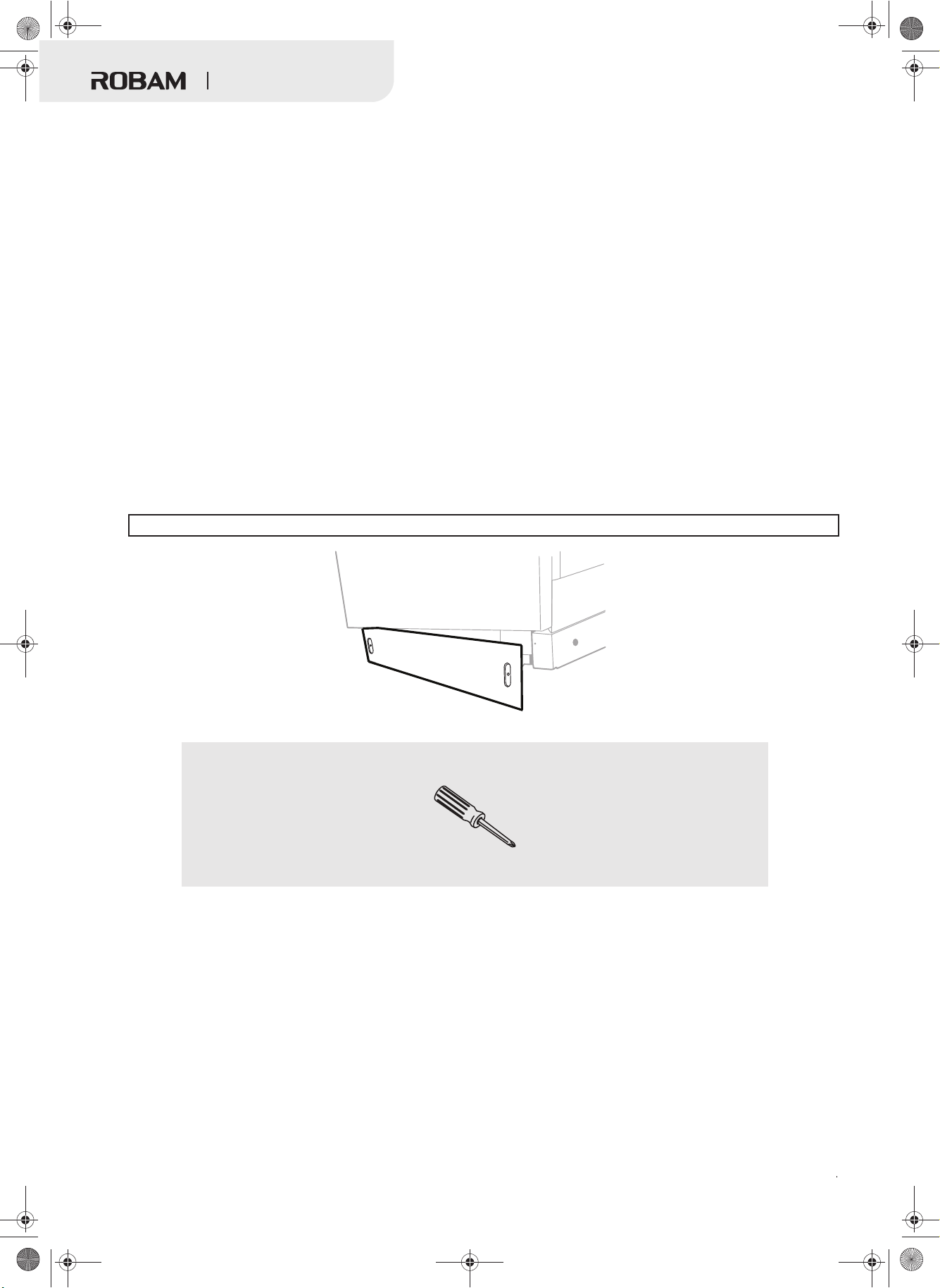
• Place the toekick against the legs of the dishwasher. The slots should align with the toekick bracket screw holes. Allow
the toekick to touch the floor. Install the toekick screws.
Make sure that you install the toekick in the correct direction. The toekick should be aligned correctly with the junction box.
Note:
You’ll need:
Phillips screwdriver
22
 Loading...