

Page 1
All Dodge Models and 200 Chevrolet Owner ’s Manual
Including
Limited Warranty Information
Page 2

WARNINGS & CAUTIONS
DDoocc NNoo::
MNSA0006 Rev: 00
CCooppyyrriigghhtt©© HHaannmmaarr MMoottoorr CCoorrppoorraattiioonn 22000033
WARNINGS AND CAUTIONS
This manual contains WARNINGS against operating
procedures which could result in an accident or bodily injury.
The manual also contains CAUTIONS against procedures
which could result in damage to your vehicle.
If you do not read the entire manual you may miss important
information. Observe all Warnings & Cautions.
WARNINGS & CAUTIONS
DDoocc NNoo::
MNSA0006 Rev: 00
CCooppyyrriigghhtt©© HHaannmmaarr MMoottoorr CCoorrppoorraattiioonn 22000033
WARNINGS AND CAUTIONS
This manual contains WARNINGS against operating
procedures which could result in an accident or bodily injury.
The manual also contains CAUTIONS against procedures
which could result in damage to your vehicle.
If you do not read the entire manual you may miss important
information. Observe all Warnings & Cautions.
Page 3

TABLE OF CONTENTS
DDoocc NNoo::
MNSA0006 Rev: 00
CCooppyyrriigghhtt©© HHaannmmaarr MMoottoorr CCoorrppoorraattiioonn 22000033 BB -- 11
Introduction ________________________________________________________________________________Preface
Elevations __________________________________________________________________________________Preface
Daily Living ____________________________________________________________________________________A-1
Captain’s Seats __________________________________________________________________________________A-1
Seat Belt Usage ________________________________________________________________________________A-1
Dinette Table (190-Versatile with Dinette Only)________________________________________________________A-1
Cloverleaf Dining Table (190 and 200 Models) ________________________________________________________A-2
Extendible Dining Table __________________________________________________________________________A-2
Exterior Access Doors ____________________________________________________________________________A-2
Spare Tire Storage and Removal ____________________________________________________________________A-3
Sleeping Facilities ______________________________________________________________________________B-1
Rear L-Shaped Lounge to Double Bed (170-Popular and 190-Versatile) ____________________________________B-1
Rear L-Shaped Lounge to Double Bed (200-Versatile) __________________________________________________B-1
Rear Dinette to Double Bed (190-Versatile) __________________________________________________________B-2
Rear Twin Beds (190-Popular and 200-Popular) ________________________________________________________B-2
Rear King-Size Bed (190-Popular and 200-Popular) ____________________________________________________B-2
Front Lounge Seats (All Models) ____________________________________________________________________B-3
Appliance Location ____________________________________________________________________________C-1
Washroom and Privacy Area ____________________________________________________________________D-1
Privacy Doors (170-Popular, 190-Popular and 200-Popular) ______________________________________________D-1
Privacy Doors (190-Versatile) ______________________________________________________________________D-1
Privacy Doors (200-Versatile) ______________________________________________________________________D-1
Toilet ________________________________________________________________________________________D-2
Stand-Up Aisle Shower __________________________________________________________________________D-2
Water System __________________________________________________________________________________E-1
Fresh Water Tank ________________________________________________________________________________E-1
City Water Connection ____________________________________________________________________________E-1
Waste Water Storage and Dumping System __________________________________________________________E-2
Waste Tank Preparation __________________________________________________________________________E-2
Waste Tank Dumping ____________________________________________________________________________E-2
Waste Tank Flushing______________________________________________________________________________E-3
Potable Water System Draining ____________________________________________________________________E-3
Potable Water System Sanitizing __________________________________________________________________E-3
Potable Water System Winterizing __________________________________________________________________E-4
Water Heater Bypass ____________________________________________________________________________E-4
Winter Use ____________________________________________________________________________________E-4
Electrical System________________________________________________________________________________F-1
110/12V Converter Charger ________________________________________________________________________F-1
External Electrical Source Connection ______________________________________________________________F-1
Generator (Optional) ____________________________________________________________________________F-1
Built-In 110V Air Conditioner ______________________________________________________________________F-1
Monitor Panel __________________________________________________________________________________F-2
Auxiliary Battery and Isolator ______________________________________________________________________F-2
Automotive Battery ______________________________________________________________________________F-3
Interior Cab Light and Ignition Light ________________________________________________________________F-3
Driving ________________________________________________________________________________________F-3
Stationary Use (Doors Closed) ______________________________________________________________________F-3
TABLE OF CONTENTS
DDoocc NNoo::
MNSA0006 Rev: 00
CCooppyyrriigghhtt©© HHaannmmaarr MMoottoorr CCoorrppoorraattiioonn 22000033 BB -- 11
Introduction ________________________________________________________________________________Preface
Elevations __________________________________________________________________________________Preface
Daily Living ____________________________________________________________________________________A-1
Captain’s Seats __________________________________________________________________________________A-1
Seat Belt Usage ________________________________________________________________________________A-1
Dinette Table (190-Versatile with Dinette Only)________________________________________________________A-1
Cloverleaf Dining Table (190 and 200 Models) ________________________________________________________A-2
Extendible Dining Table __________________________________________________________________________A-2
Exterior Access Doors ____________________________________________________________________________A-2
Spare Tire Storage and Removal ____________________________________________________________________A-3
Sleeping Facilities ______________________________________________________________________________B-1
Rear L-Shaped Lounge to Double Bed (170-Popular and 190-Versatile) ____________________________________B-1
Rear L-Shaped Lounge to Double Bed (200-Versatile) __________________________________________________B-1
Rear Dinette to Double Bed (190-Versatile) __________________________________________________________B-2
Rear Twin Beds (190-Popular and 200-Popular) ________________________________________________________B-2
Rear King-Size Bed (190-Popular and 200-Popular) ____________________________________________________B-2
Front Lounge Seats (All Models) ____________________________________________________________________B-3
Appliance Location ____________________________________________________________________________C-1
Washroom and Privacy Area ____________________________________________________________________D-1
Privacy Doors (170-Popular, 190-Popular and 200-Popular) ______________________________________________D-1
Privacy Doors (190-Versatile) ______________________________________________________________________D-1
Privacy Doors (200-Versatile) ______________________________________________________________________D-1
Toilet ________________________________________________________________________________________D-2
Stand-Up Aisle Shower __________________________________________________________________________D-2
Water System __________________________________________________________________________________E-1
Fresh Water Tank ________________________________________________________________________________E-1
City Water Connection ____________________________________________________________________________E-1
Waste Water Storage and Dumping System __________________________________________________________E-2
Waste Tank Preparation __________________________________________________________________________E-2
Waste Tank Dumping ____________________________________________________________________________E-2
Waste Tank Flushing______________________________________________________________________________E-3
Potable Water System Draining ____________________________________________________________________E-3
Potable Water System Sanitizing __________________________________________________________________E-3
Potable Water System Winterizing __________________________________________________________________E-4
Water Heater Bypass ____________________________________________________________________________E-4
Winter Use ____________________________________________________________________________________E-4
Electrical System________________________________________________________________________________F-1
110/12V Converter Charger ________________________________________________________________________F-1
External Electrical Source Connection ______________________________________________________________F-1
Generator (Optional) ____________________________________________________________________________F-1
Built-In 110V Air Conditioner ______________________________________________________________________F-1
Monitor Panel __________________________________________________________________________________F-2
Auxiliary Battery and Isolator ______________________________________________________________________F-2
Automotive Battery ______________________________________________________________________________F-3
Interior Cab Light and Ignition Light ________________________________________________________________F-3
Driving ________________________________________________________________________________________F-3
Stationary Use (Doors Closed) ______________________________________________________________________F-3
Page 4

TABLE OF CONTENTS
DDoocc NNoo::
MNSA0006 Rev: 00
CCooppyyrriigghhtt©© HHaannmmaarr MMoottoorr CCoorrppoorraattiioonn 22000033 BB -- 11
Stationary Use (Doors Open) ______________________________________________________________________F-3
Range Hood Exhaust Fan__________________________________________________________________________F-3
L.P. Gas and Safety System ______________________________________________________________________G-1
L.P. Gas Tank ____________________________________________________________________________________G-1
Appliances ____________________________________________________________________________________G-1
Refueling Procedures ____________________________________________________________________________G-2
Regulator ______________________________________________________________________________________G-2
L.P. Gas Leak Detector ____________________________________________________________________________G-2
Carbon Monoxide Leak Detector __________________________________________________________________G-2
Smoke Detector ________________________________________________________________________________G-2
Owner Maintenance ____________________________________________________________________________H-1
Fiberglass Maintenance __________________________________________________________________________H-1
Exterior Washing ________________________________________________________________________________H-1
Other Maintenance ______________________________________________________________________________H-1
Winter Storage ________________________________________________________________________________H-1
Inside your Vehicle ______________________________________________________________________________H-1
Outside your Vehicle ____________________________________________________________________________H-1
Spring Start Up ________________________________________________________________________________H-2
Tires ________________________________________________________________________________________H-2
Cargo Carrying Capacity ________________________________________________________________________H-2
Owner Maintenance Checks ______________________________________________________________________H-2
When You Stop for Fuel __________________________________________________________________________H-2
At Least Monthly ________________________________________________________________________________H-2
At Least Once Every Three Months __________________________________________________________________H-2
At Least Twice a Year ____________________________________________________________________________H-3
At Least Once a Year ____________________________________________________________________________H-3
Auxiliary Battery ________________________________________________________________________________H-3
Limited Warranty Information ____________________________________________________________________I-1
Definitions ______________________________________________________________________________________I-1
Home & Park Limited Warranty Registration Card ______________________________________________________I-1
Automotive Warranty- Chrysler (Dodge Chassis) . ______________________________________________________I-1
Automotive Warranty - General Motors (Chevrolet Chassis) ______________________________________________I-2
Automotive Customer Service & Roadside Assistance Numbers __________________________________________I-2
Appliance Warranty ______________________________________________________________________________I-2
Home & Park Motorhomes Limited Warranty ________________________________________________________I-3
Reporting Safety Defects (U.S. only) ______________________________________________________________I-4
Potential Customer Referral Program ______________________________________________________________J-1
Roadtrek Club International ______________________________________________________________________J-1
Address, Phone & Facsimile Numbers, and E-mail____________________________________________________J-2
Website________________________________________________________________________________________J-2
Obtaining Motorhome Service __________________________________________________________________K-1
Roadtrek International Chapter FMCA - Membership Application ____________________________________L-1
Change of Address Form ________________________________________________________________________L-2
Customer Referral Card __________________________________________________________________________L-5
TABLE OF CONTENTS
DDoocc NNoo::
MNSA0006 Rev: 00
CCooppyyrriigghhtt©© HHaannmmaarr MMoottoorr CCoorrppoorraattiioonn 22000033 BB -- 11
Stationary Use (Doors Open) ______________________________________________________________________F-3
Range Hood Exhaust Fan__________________________________________________________________________F-3
L.P. Gas and Safety System ______________________________________________________________________G-1
L.P. Gas Tank ____________________________________________________________________________________G-1
Appliances ____________________________________________________________________________________G-1
Refueling Procedures ____________________________________________________________________________G-2
Regulator ______________________________________________________________________________________G-2
L.P. Gas Leak Detector ____________________________________________________________________________G-2
Carbon Monoxide Leak Detector __________________________________________________________________G-2
Smoke Detector ________________________________________________________________________________G-2
Owner Maintenance ____________________________________________________________________________H-1
Fiberglass Maintenance __________________________________________________________________________H-1
Exterior Washing ________________________________________________________________________________H-1
Other Maintenance ______________________________________________________________________________H-1
Winter Storage ________________________________________________________________________________H-1
Inside your Vehicle ______________________________________________________________________________H-1
Outside your Vehicle ____________________________________________________________________________H-1
Spring Start Up ________________________________________________________________________________H-2
Tires ________________________________________________________________________________________H-2
Cargo Carrying Capacity ________________________________________________________________________H-2
Owner Maintenance Checks ______________________________________________________________________H-2
When You Stop for Fuel __________________________________________________________________________H-2
At Least Monthly ________________________________________________________________________________H-2
At Least Once Every Three Months __________________________________________________________________H-2
At Least Twice a Year ____________________________________________________________________________H-3
At Least Once a Year ____________________________________________________________________________H-3
Auxiliary Battery ________________________________________________________________________________H-3
Limited Warranty Information ____________________________________________________________________I-1
Definitions ______________________________________________________________________________________I-1
Home & Park Limited Warranty Registration Card ______________________________________________________I-1
Automotive Warranty- Chrysler (Dodge Chassis) . ______________________________________________________I-1
Automotive Warranty - General Motors (Chevrolet Chassis) ______________________________________________I-2
Automotive Customer Service & Roadside Assistance Numbers __________________________________________I-2
Appliance Warranty ______________________________________________________________________________I-2
Home & Park Motorhomes Limited Warranty ________________________________________________________I-3
Reporting Safety Defects (U.S. only) ______________________________________________________________I-4
Potential Customer Referral Program ______________________________________________________________J-1
Roadtrek Club International ______________________________________________________________________J-1
Address, Phone & Facsimile Numbers, and E-mail____________________________________________________J-2
Website________________________________________________________________________________________J-2
Obtaining Motorhome Service __________________________________________________________________K-1
Roadtrek International Chapter FMCA - Membership Application ____________________________________L-1
Change of Address Form ________________________________________________________________________L-2
Customer Referral Card __________________________________________________________________________L-5
Page 5
INTRODUCTION
DDoocc NNoo::
MNSA0006 Rev: 00
CCooppyyrriigghhtt©© HHaannmmaarr MMoottoorr CCoorrppoorraattiioonn 22000033 AA..00
A WORD TO ROADTREK OWNERS...
This manual has been prepared to acquaint you with the operation, maintenance and warranties of your new
Roadtrek Motorhome Van. Your vehicle has been designed, engineered and manufactured to provide you with
the utmost in pleasure, dependability and quality. It is important that you read the contents of this manual, that of
the Chevrolet chassis and those of other components, and follow the instructions and recommendations contained
in each to help assure the most enjoyable and trouble free operation of your vehicle.
We would like to take this opportunity to thank you for selecting a Home & Park product and assure you of our
continuing commitment to your recreational vehicle pleasure, safety and satisfaction.
INTRODUCTION
This manual has been written to provide you with the information required to properly operate and maintain your
new Roadtrek. After reading this manual, be sure to keep it in your vehicle as a reference.Your Home & Park dealer
will be glad to answer any further questions about the operation of your vehicle.
IMPORTANT
Every reasonable precaution has been undertaken in the preparation of this manual resulting in the utmost
accuracy possible at the time of publication. However,due to the continuing improvement and refinement of our
products and normal changes in information and procedures, Home & Park shall assume no responsibility
whatsoever for errors or omissions in the manual’s contents.
Further, Home & Park shall not be held liable or assume any obligations or responsibilities whatsoever for any loss,
damage or injury directly or indirectly caused by, arising or resulting from,or as a consequence of the use or
nonuse of the information contained herein or the operation or non-operation of any items mentioned herein.And
finally,Home & Park shall be indemnified and saved harmless from all losses, expenses, claims and demands
whatsoever.
INTRODUCTION
DDoocc NNoo::
MNSA0006 Rev: 00
CCooppyyrriigghhtt©© HHaannmmaarr MMoottoorr CCoorrppoorraattiioonn 22000033 AA..00
A WORD TO ROADTREK OWNERS...
This manual has been prepared to acquaint you with the operation, maintenance and warranties of your new
Roadtrek Motorhome Van. Your vehicle has been designed, engineered and manufactured to provide you with
the utmost in pleasure, dependability and quality. It is important that you read the contents of this manual, that of
the Chevrolet chassis and those of other components, and follow the instructions and recommendations contained
in each to help assure the most enjoyable and trouble free operation of your vehicle.
We would like to take this opportunity to thank you for selecting a Home & Park product and assure you of our
continuing commitment to your recreational vehicle pleasure, safety and satisfaction.
INTRODUCTION
This manual has been written to provide you with the information required to properly operate and maintain your
new Roadtrek. After reading this manual, be sure to keep it in your vehicle as a reference.Your Home & Park dealer
will be glad to answer any further questions about the operation of your vehicle.
IMPORTANT
Every reasonable precaution has been undertaken in the preparation of this manual resulting in the utmost
accuracy possible at the time of publication. However,due to the continuing improvement and refinement of our
products and normal changes in information and procedures, Home & Park shall assume no responsibility
whatsoever for errors or omissions in the manual’s contents.
Further, Home & Park shall not be held liable or assume any obligations or responsibilities whatsoever for any loss,
damage or injury directly or indirectly caused by, arising or resulting from,or as a consequence of the use or
nonuse of the information contained herein or the operation or non-operation of any items mentioned herein.And
finally,Home & Park shall be indemnified and saved harmless from all losses, expenses, claims and demands
whatsoever.
Page 6
INTRODUCTION
DDoocc NNoo::
MNSA0006 Rev: 00
CCooppyyrriigghhtt©© HHaannmmaarr MMoottoorr CCoorrppoorraattiioonn 22000033
Gross Combination Weight Rating (GCWR)
The Chevrolet 3500 extended van has a GCWR of 6350
Kg/14000 lbs for the standard engine (6.0 L) and 7258
Kg/16000 lbs for the optional 4.10 rear axle ratio.
Gross Vehicle Weight Rating (GVWR): is the maximum
permissible weight of this vehicle when fully loaded. It
includes all weight at the vehicle axle(s).
Unloaded Vehicle Weight (UVW): is the weight of this
motorhome as manufactured at the factory. It includes all
weight at the vehicle axle(s). If applicable,it also includes full
generator fluids, including fuel, engine oil and coolants.
Cargo Carrying Capacity (CCC): is equal to GVWR minus
each of the following: UVW, full fresh (potable) water weight
(including water heater), and full LP-Gas weight and SCWR.
Gross Combination Weight Rating (GCWR): (motorhomes
only): means the maximum allowable loaded weight of this
motorhome and any towed trailer or towed vehicle.
Sleeping Capacity Weight Rating (SCWR): (motorhomes
only): is the manufacturer’s designated number of sleeping
positions multiplied by 154 pounds (70 kilograms).
Gross Axle Weight Rating (GAWR): is the value specified as
the load carrying capacity of a single axle system, as
measured at the tire-ground interfaces.
Towing Guidelines: Consult Chevrolet Owners Manual(s) for
specific weighing instructions and towing guidelines
including auxiliary brake requirements for any towed trailer
or towed vehicle.
Weighing Procedure: Prior to weighing each unit, the fuel tank must be full,as well as the fresh water tank. All tires
must be of equal pressure, and any snow must be removed.
Note the weighing must be done on level ground!
Equipment: 2 Portable Scales (including electrical power source), 2 wooden ramps, Lift and pressure guage.
Alternate: D.O.T. approved customer scales
Note: Wooden ramps must be equal to or less than 1/8”of the height of the scales being used.
Procedure:
1) Fill Fuel Tank
2) Fill Fresh Water Tank
3) Measure all tire pressures and equalize if necessary
4) Place wooden ramps below rear wheels (using lift or driving onto ramps for levelling vehicle,; N/A if
commercial scales used)
5) Place scales under front wheels
6) Record scale readings
7) Repeat for rear wheels
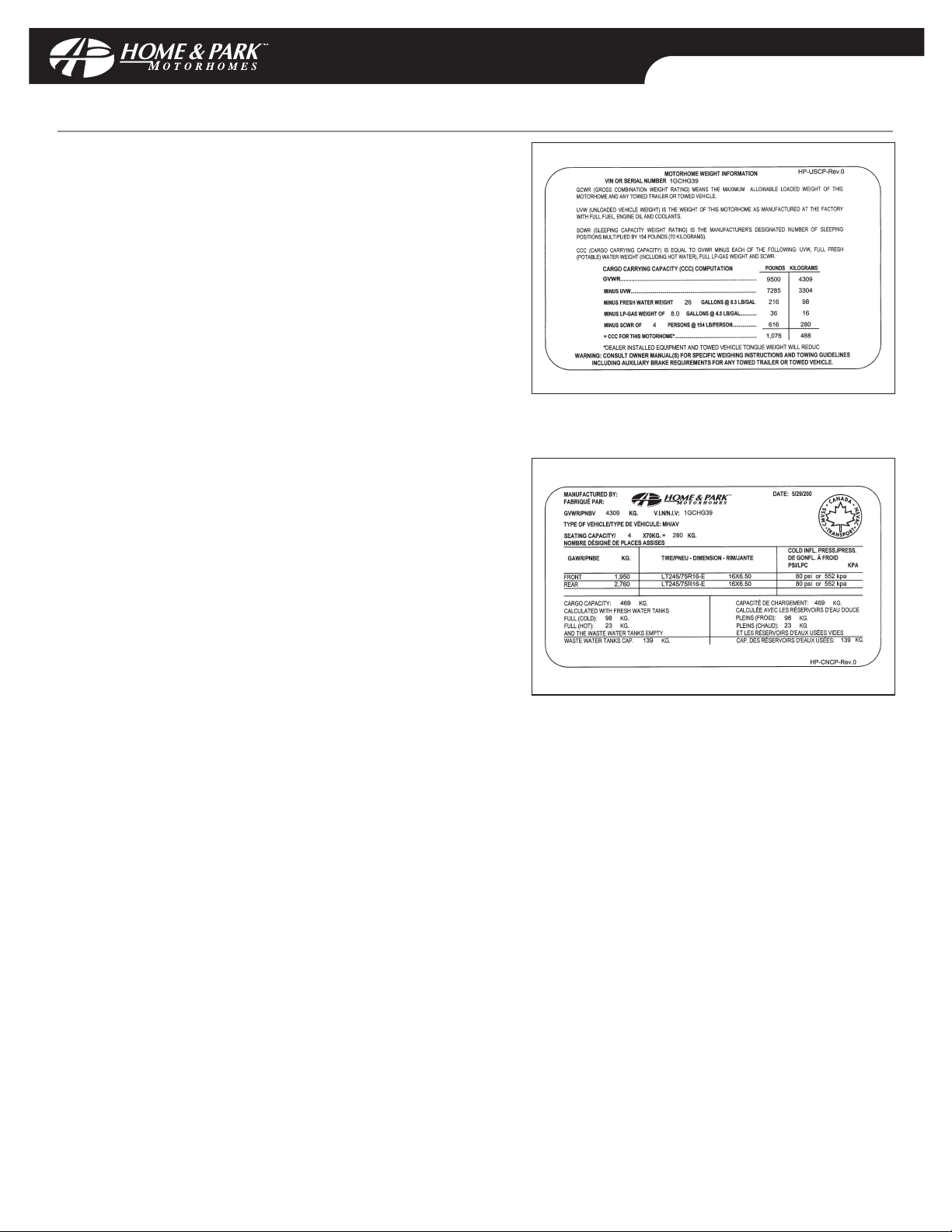
Sample of Canadian Weight label:
Sample of US Weight label:
INTRODUCTION
DDoocc NNoo::
MNSA0006 Rev: 00
CCooppyyrriigghhtt©© HHaannmmaarr MMoottoorr CCoorrppoorraattiioonn 22000033
Gross Combination Weight Rating (GCWR)
The Chevrolet 3500 extended van has a GCWR of 6350
Kg/14000 lbs for the standard engine (6.0 L) and 7258
Kg/16000 lbs for the optional 4.10 rear axle ratio.
Gross Vehicle Weight Rating (GVWR): is the maximum
permissible weight of this vehicle when fully loaded. It
includes all weight at the vehicle axle(s).
Unloaded Vehicle Weight (UVW): is the weight of this
motorhome as manufactured at the factory. It includes all
weight at the vehicle axle(s). If applicable,it also includes full
generator fluids, including fuel, engine oil and coolants.
Cargo Carrying Capacity (CCC): is equal to GVWR minus
each of the following: UVW, full fresh (potable) water weight
(including water heater), and full LP-Gas weight and SCWR.
Gross Combination Weight Rating (GCWR): (motorhomes
only): means the maximum allowable loaded weight of this
motorhome and any towed trailer or towed vehicle.
Sleeping Capacity Weight Rating (SCWR): (motorhomes
only): is the manufacturer’s designated number of sleeping
positions multiplied by 154 pounds (70 kilograms).
Gross Axle Weight Rating (GAWR): is the value specified as
the load carrying capacity of a single axle system, as
measured at the tire-ground interfaces.
Towing Guidelines: Consult Chevrolet Owners Manual(s) for
specific weighing instructions and towing guidelines
including auxiliary brake requirements for any towed trailer
or towed vehicle.
Weighing Procedure: Prior to weighing each unit, the fuel tank must be full,as well as the fresh water tank. All tires
must be of equal pressure, and any snow must be removed.
Note the weighing must be done on level ground!
Equipment: 2 Portable Scales (including electrical power source), 2 wooden ramps, Lift and pressure guage.
Alternate: D.O.T. approved customer scales
Note: Wooden ramps must be equal to or less than 1/8”of the height of the scales being used.
Procedure:
1) Fill Fuel Tank
2) Fill Fresh Water Tank
3) Measure all tire pressures and equalize if necessary
4) Place wooden ramps below rear wheels (using lift or driving onto ramps for levelling vehicle,; N/A if
commercial scales used)
5) Place scales under front wheels
6) Record scale readings
7) Repeat for rear wheels
Sample of Canadian Weight label:
Sample of US Weight label:
Page 7
ELEVATIONS
DDoocc NNoo::
MNSA0006 Rev: 00
CCooppyyrriigghhtt©© HHaannmmaarr MMoottoorr CCoorrppoorraattiioonn 22000033 BB -- 11
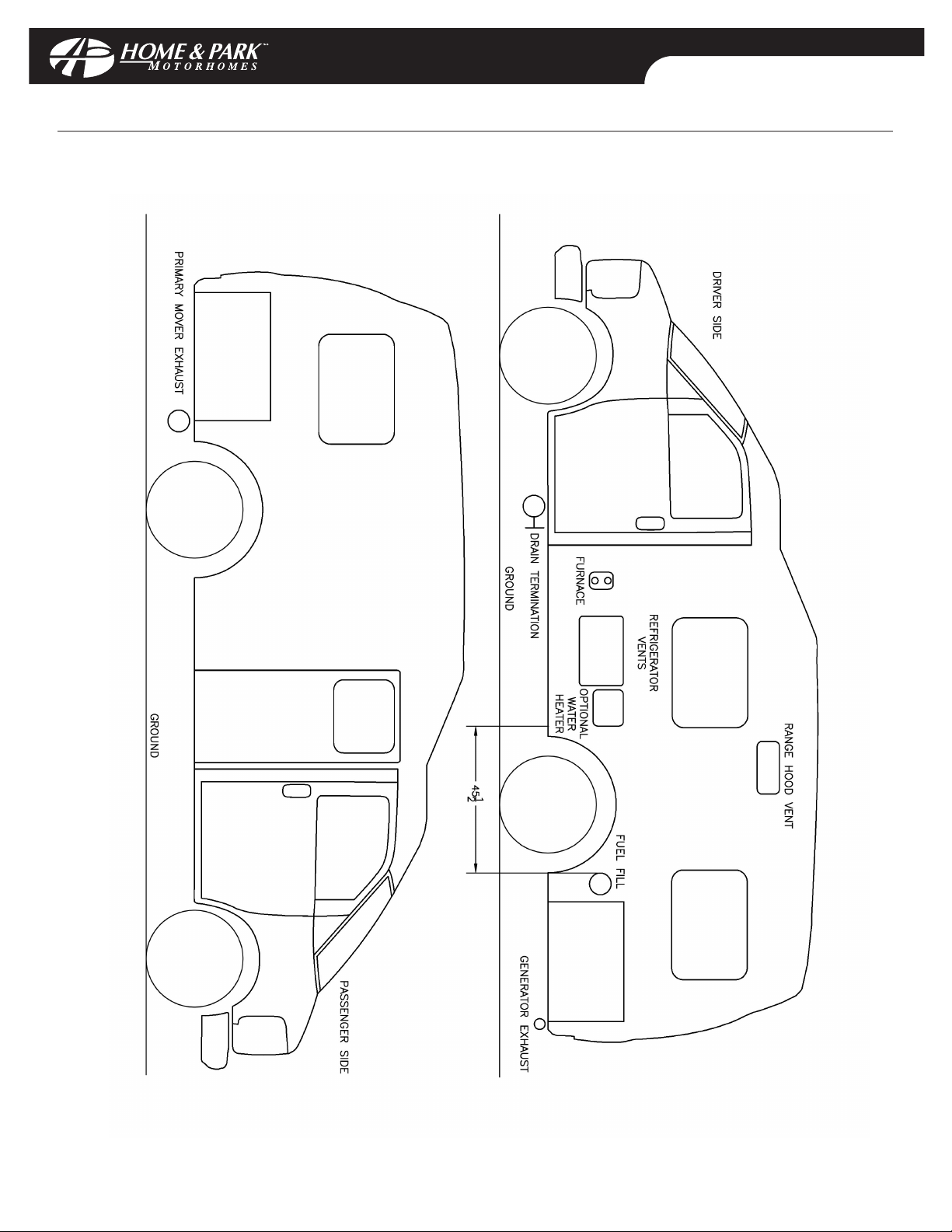
200-POPULAR
ELEVATIONS
DDoocc NNoo::
MNSA0006 Rev: 00
CCooppyyrriigghhtt©© HHaannmmaarr MMoottoorr CCoorrppoorraattiioonn 22000033 BB -- 11
200-POPULAR
Page 8
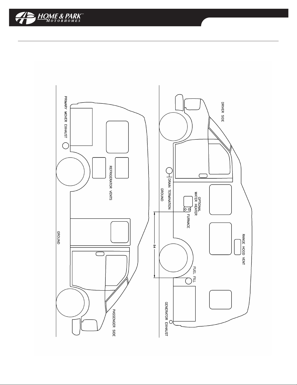
ELEVATIONS
DDoocc NNoo::
MNSA0006 Rev: 00
CCooppyyrriigghhtt©© HHaannmmaarr MMoottoorr CCoorrppoorraattiioonn 22000033 BB -- 11
200-VERSATILE
ELEVATIONS
DDoocc NNoo::
MNSA0006 Rev: 00
CCooppyyrriigghhtt©© HHaannmmaarr MMoottoorr CCoorrppoorraattiioonn 22000033 BB -- 11
200-VERSATILE
Page 9
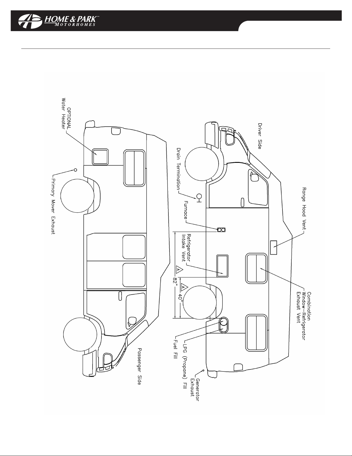
ELEVATIONS
DDoocc NNoo::
MNSA0006 Rev: 00
CCooppyyrriigghhtt©© HHaannmmaarr MMoottoorr CCoorrppoorraattiioonn 22000033 BB -- 11
190-POPULAR
ELEVATIONS
DDoocc NNoo::
MNSA0006 Rev: 00
CCooppyyrriigghhtt©© HHaannmmaarr MMoottoorr CCoorrppoorraattiioonn 22000033 BB -- 11
190-POPULAR
Page 10
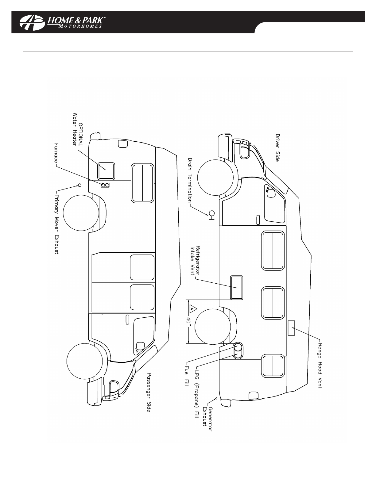
ELEVATIONS
DDoocc NNoo::
MNSA0006 Rev: 00
CCooppyyrriigghhtt©© HHaannmmaarr MMoottoorr CCoorrppoorraattiioonn 22000033 BB -- 11
190-VERSATILE
ELEVATIONS
DDoocc NNoo::
MNSA0006 Rev: 00
CCooppyyrriigghhtt©© HHaannmmaarr MMoottoorr CCoorrppoorraattiioonn 22000033 BB -- 11
190-VERSATILE
Page 11
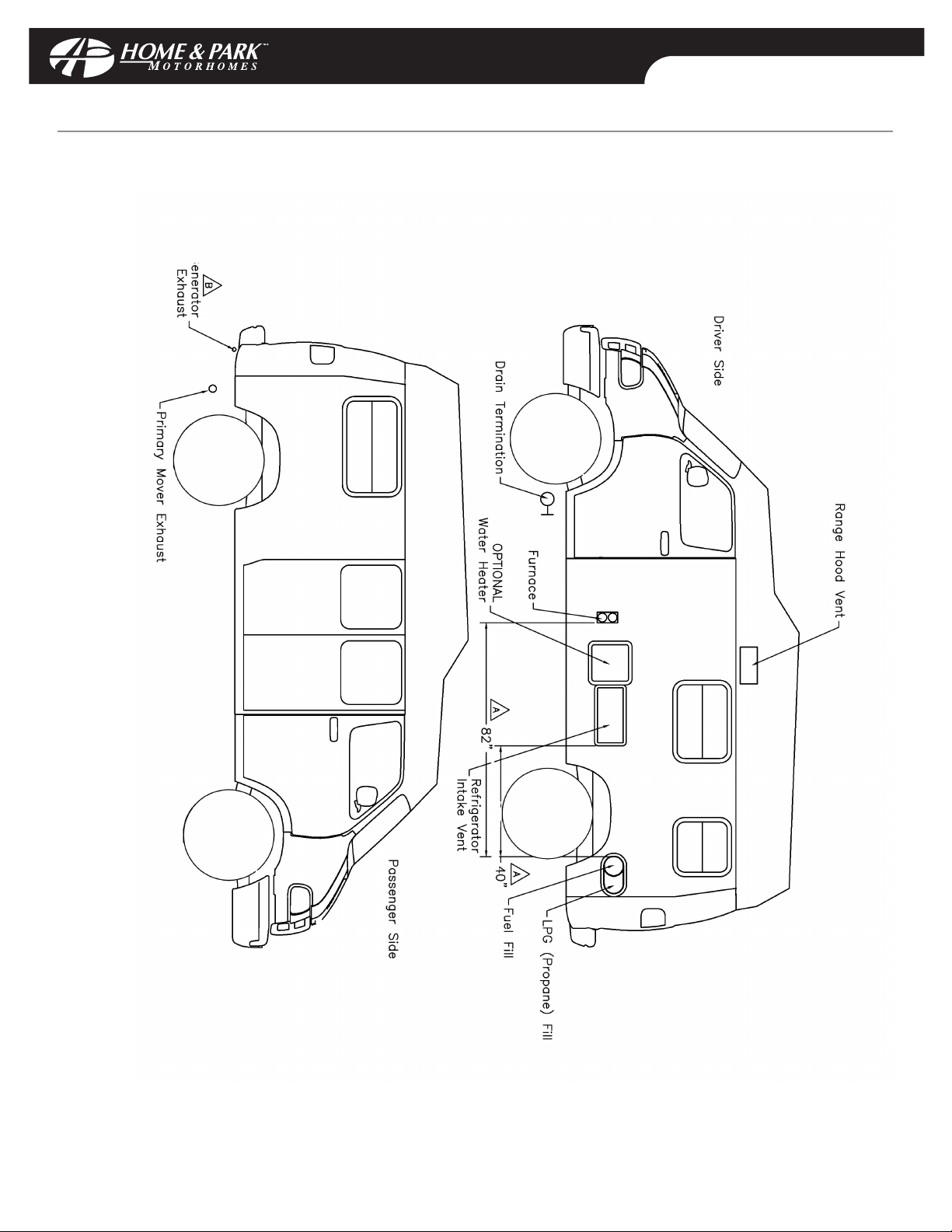
ELVEVATIONS
DDoocc NNoo::
MNSA0006 Rev: 00
CCooppyyrriigghhtt©© HHaannmmaarr MMoottoorr CCoorrppoorraattiioonn 22000033 BB -- 11
170-POPULAR
ELVEVATIONS
DDoocc NNoo::
MNSA0006 Rev: 00
CCooppyyrriigghhtt©© HHaannmmaarr MMoottoorr CCoorrppoorraattiioonn 22000033 BB -- 11
170-POPULAR
Page 12

CAPTAIN'S SEATS
To recline, pull up the recline control located below the inboard arm rest and lean back.
To slide the seat of Dodge models, pull the slide control located on the left underside of the seat outward, and slide
the seat either forward or back. On Chevrolet models, pull the slide control located on the front lower side of the
seat upward, and slide the seat either forward or back.
To swivel the seats from a forward facing position to a rearward facing position, be aware of the following:
i) Ensure that the back of the seat is reclined as far forward as the recline control allows.
ii) Slide the seat forward but not so far as to lose clearance of the engine cover.
iii) Put the tilt steering wheel in the uppermost position.
iv) The swivel control is located on the center front underside of the seat and locks the seat in a forward
facing position. To release, pull up on the swivel control and turn the seat inward (clockwise for the driver
side seat and counterclockwise for the passenger seat).
v) Swivel the seat to the desired position.
vi) Once completed, lower the tilt steering wheel and adjust the recline and slide controls as desired.
SEAT BELT USAGE
For protection, while your vehicle is in motion, everybody inside the vehicle must wear a seat belt. The driver and
passenger captains seats and the lounge seat(s) immediately behind are designed to carry passengers while your
vehicle is in motion and are equipped with seat belts installed for their protection. All passengers must be seated
in these seats only with seat belts fastened while the vehicle is in motion.
Some vans are equipped with lap belts for extra seating while in motion (forward facing seats in an L-shaped
lounge option). The lap belts must be worn across the hips and not across the abdomen. Passengers must sit well
back in the seat and in an upright position.
DINETTE TABLE (190-VERSATILE WITH DINETTE ONLY)
The rear dinette table can be used with the front captain's seats and lounge seats (without removable wardrobe)
instead of the cloverleaf dining table. To use the dinette table at the front:
i) Remove the cloverleaf table from its table leg.
ii) Leave the table leg in the base in the floor at the front.
iii) Swivel the driver captain's seat into a rearward facing position (see Captain’s Seats A-1).
iv) Place the dinette table on this table leg with the other end resting on the drink holders mounted on the
wall below the awning window.
DAILY LIVING
DDoocc NNoo::
MNSA0006 Rev: 00
CCooppyyrriigghhtt©© HHaannmmaarr MMoottoorr CCoorrppoorraattiioonn 22000033 AA--11
CAPTAIN'S SEATS
To recline, pull up the recline control located below the inboard arm rest and lean back.
To slide the seat of Dodge models, pull the slide control located on the left underside of the seat outward, and slide
the seat either forward or back. On Chevrolet models, pull the slide control located on the front lower side of the
seat upward, and slide the seat either forward or back.
To swivel the seats from a forward facing position to a rearward facing position, be aware of the following:
i) Ensure that the back of the seat is reclined as far forward as the recline control allows.
ii) Slide the seat forward but not so far as to lose clearance of the engine cover.
iii) Put the tilt steering wheel in the uppermost position.
iv) The swivel control is located on the center front underside of the seat and locks the seat in a forward
facing position. To release, pull up on the swivel control and turn the seat inward (clockwise for the driver
side seat and counterclockwise for the passenger seat).
v) Swivel the seat to the desired position.
vi) Once completed, lower the tilt steering wheel and adjust the recline and slide controls as desired.
SEAT BELT USAGE
For protection, while your vehicle is in motion, everybody inside the vehicle must wear a seat belt. The driver and
passenger captains seats and the lounge seat(s) immediately behind are designed to carry passengers while your
vehicle is in motion and are equipped with seat belts installed for their protection. All passengers must be seated
in these seats only with seat belts fastened while the vehicle is in motion.
Some vans are equipped with lap belts for extra seating while in motion (forward facing seats in an L-shaped
lounge option). The lap belts must be worn across the hips and not across the abdomen. Passengers must sit well
back in the seat and in an upright position.
DINETTE TABLE (190-VERSATILE WITH DINETTE ONLY)
The rear dinette table can be used with the front captain's seats and lounge seats (without removable wardrobe)
instead of the cloverleaf dining table. To use the dinette table at the front:
i) Remove the cloverleaf table from its table leg.
ii) Leave the table leg in the base in the floor at the front.
iii) Swivel the driver captain's seat into a rearward facing position (see Captain’s Seats A-1).
iv) Place the dinette table on this table leg with the other end resting on the drink holders mounted on the
wall below the awning window.
DAILY LIVING
DDoocc NNoo::
MNSA0006 Rev: 00
CCooppyyrriigghhtt©© HHaannmmaarr MMoottoorr CCoorrppoorraattiioonn 22000033 AA--11
Page 13
DAILY LIVING
DDoocc NNoo::
MNSA0006 Rev: 00
CCooppyyrriigghhtt©© HHaannmmaarr MMoottoorr CCoorrppoorraattiioonn 22000033 AA--22
CLOVERLEAF DINING TABLE (190 AND 200 MODELS)
To use the "leaves":
i) Pivot the table into the desired position.
ii) In a seated position, with one hand under the table,push the support device out toward you.
iii) Let the "leaf" fall and push the support device back in to allow the "leaf" to be swung up parallel to the
table surface.
iv) Pull the support device back toward yourself (to support the extended leaf ).
To return the "leaf" to its original position, follow these steps in reverse order.
EXTENDIBLE DINING TABLE
To extend the table:
i) Remove the table from its table leg.
ii) Leave the table leg in the base in the floor.
iii) Unlock the extendible leaf and extend the table.
iv) Secure the extended leaf by rotating the bracket under the table until it stops.
v) Place the table on the table leg with the extended small leaf resting on the drink holders mounted on
the wall below the awning window.
To return the table to the original size follow these steps in the reverse order.
EXTERIOR ACCESS DOORS
Most utilities are located behind exterior doors integrated into the following locations:
Utility All Chevrolet Models All Dodge Models
LP gas fill valve door integrated into rear fuel filler door behind driver rear wheel
bumper behind the license plate
LP gas tank and regulator door integrated into rear below floor and behind
bumper behind the license plate rear axle
LP gas gauge door integrated into rear monitor panel inside and above
bumper behind the license plate passenger lounge seat
Sewage hose assembly black and small door integrated within small door integrated within
grey water gate valve handles running boards below driver step running boards below driver step
Fresh water tank low point drain at tank under vehicle on tank behind driver rear wheel
Fresh water fill side entry door step well passenger side rear door post
Exterior accessible storage large lockable door integrated within large lockable door integrated within
compartments (maximum capacity running boards behind driver step running boards behind driver step
of 70 Kg or 150 lbs.each)
Power cord lockable door integrated into flare large lockable door integrated within
External TV cable connection behind driver side rear wheel running boards behind driver step
City water connection
External shower
DAILY LIVING
DDoocc NNoo::
MNSA0006 Rev: 00
CCooppyyrriigghhtt©© HHaannmmaarr MMoottoorr CCoorrppoorraattiioonn 22000033 AA--22
CLOVERLEAF DINING TABLE (190 AND 200 MODELS)
To use the "leaves":
i) Pivot the table into the desired position.
ii) In a seated position, with one hand under the table,push the support device out toward you.
iii) Let the "leaf" fall and push the support device back in to allow the "leaf" to be swung up parallel to the
table surface.
iv) Pull the support device back toward yourself (to support the extended leaf ).
To return the "leaf" to its original position, follow these steps in reverse order.
EXTENDIBLE DINING TABLE
To extend the table:
i) Remove the table from its table leg.
ii) Leave the table leg in the base in the floor.
iii) Unlock the extendible leaf and extend the table.
iv) Secure the extended leaf by rotating the bracket under the table until it stops.
v) Place the table on the table leg with the extended small leaf resting on the drink holders mounted on
the wall below the awning window.
To return the table to the original size follow these steps in the reverse order.
EXTERIOR ACCESS DOORS
Most utilities are located behind exterior doors integrated into the following locations:
Utility All Chevrolet Models All Dodge Models
LP gas fill valve door integrated into rear fuel filler door behind driver rear wheel
bumper behind the license plate
LP gas tank and regulator door integrated into rear below floor and behind
bumper behind the license plate rear axle
LP gas gauge door integrated into rear monitor panel inside and above
bumper behind the license plate passenger lounge seat
Sewage hose assembly black and small door integrated within small door integrated within
grey water gate valve handles running boards below driver step running boards below driver step
Fresh water tank low point drain at tank under vehicle on tank behind driver rear wheel
Fresh water fill side entry door step well passenger side rear door post
Exterior accessible storage large lockable door integrated within large lockable door integrated within
compartments (maximum capacity running boards behind driver step running boards behind driver step
of 70 Kg or 150 lbs.each)
Power cord lockable door integrated into flare large lockable door integrated within
External TV cable connection behind driver side rear wheel running boards behind driver step
City water connection
External shower
Page 14

DAILY LIVING
DDoocc NNoo::
MNSA0006 Rev: 00
CCooppyyrriigghhtt©© HHaannmmaarr MMoottoorr CCoorrppoorraattiioonn 22000033 AA--33
SPARE TIRE STORAGE AND REMOVAL
For vehicles not equipped with an optional "Continental" spare tire carrier, the spare tire is stored within the
storage area below the rear bed or on the underside of your vehicle behind the rear axle (only Dodge 190 models
without generators or trailer hitches).
To remove the spare tire from the underside of your vehicle behind the rear axle:
i) Insert tire iron into opening located on bottom center of rear door frame.
ii) Turn counterclockwise to lower tire.
iii) Remove support hook and cable from the tire.
For models equipped with an optional "Continental" spare tire carrier mounted on the rear door, to remove the
spare tire:
i) Release the locking clamp located on the underside of the chrome outer ring (will require a key if so
equipped).
ii) While holding the center fiberglass dish in place,spread the outer ring by pulling outward from the
bottom.
iii) Remove the center dish and outer ring from around the tire.
vi) Using the tire iron, remove the lug nuts that secure the tire to the carrier.
v) Brace yourself for the weight of the tire (40 Kg/80 lbs.), and pull the tire from the carrier and lower it to
the ground.
To store the spare tire, perform these steps in reverse order.
CAUTION: On vehicles equipped with an optional "Continental" spare tire carrier,hold onto the door securely
during windy conditions and do not open the door with excessive force to prevent it from opening beyond its
normal limitation and causing damage to the door or its hinges.
DAILY LIVING
DDoocc NNoo::
MNSA0006 Rev: 00
CCooppyyrriigghhtt©© HHaannmmaarr MMoottoorr CCoorrppoorraattiioonn 22000033 AA--33
SPARE TIRE STORAGE AND REMOVAL
For vehicles not equipped with an optional "Continental" spare tire carrier, the spare tire is stored within the
storage area below the rear bed or on the underside of your vehicle behind the rear axle (only Dodge 190 models
without generators or trailer hitches).
To remove the spare tire from the underside of your vehicle behind the rear axle:
i) Insert tire iron into opening located on bottom center of rear door frame.
ii) Turn counterclockwise to lower tire.
iii) Remove support hook and cable from the tire.
For models equipped with an optional "Continental" spare tire carrier mounted on the rear door, to remove the
spare tire:
i) Release the locking clamp located on the underside of the chrome outer ring (will require a key if so
equipped).
ii) While holding the center fiberglass dish in place,spread the outer ring by pulling outward from the
bottom.
iii) Remove the center dish and outer ring from around the tire.
vi) Using the tire iron, remove the lug nuts that secure the tire to the carrier.
v) Brace yourself for the weight of the tire (40 Kg/80 lbs.), and pull the tire from the carrier and lower it to
the ground.
To store the spare tire, perform these steps in reverse order.
CAUTION: On vehicles equipped with an optional "Continental" spare tire carrier,hold onto the door securely
during windy conditions and do not open the door with excessive force to prevent it from opening beyond its
normal limitation and causing damage to the door or its hinges.
Page 15

DAILY LIVING
DDoocc NNoo::
MNSA0006 Rev: 00
CCooppyyrriigghhtt©© HHaannmmaarr MMoottoorr CCoorrppoorraattiioonn 22000033 BB--11
SLEEPING FACILITIES:
REAR L-SHAPED LOUNGE TO DOUBLE BED (170-POPULAR AND 190-VERSATILE)
To convert the lounge into a double bed:
i) Remove cushion under TV cabinet and store.
ii) Remove small rear back rest cushion on driver side and store.
iii) Remove table top, rotate,place on ledges between seats, and slide to front against rubber stops.
iv) Remove small narrow board stored along wall under TV cabinet and place behind the table top.
v) Lift the rear back rest cushion up from the bottom and open rear door.
vi) Remove this cushion by detaching Velcro found on back flap of backrest board and close rear door.
vii) Rotate rear seat cushion 90 degrees and place in the middle section with cushion running front to back.
viii) With the rear back cushion in hand,separate the Velcro at the bottom edge of the cushion.
ix) Spread this cushion flat and lay it on the driver side next to the seat cushions with Velcro down.
x) Do the same with the passenger side back rest cushion by pulling the Velcro apart at the top edge of the
cushion, and lay it on top of the other back rest cushion with Velcro up.
To convert back to a lounge, perform these steps in reverse order.
REAR L-SHAPED LOUNGE TO DOUBLE BED (200-VERSATILE)
To convert the lounge into a double bed:
i) Remove cushion under TV cabinet and store.
ii) Remove small rear back rest cushion on driver side and store.
iii) Remove table top, rotate,place on ledges between seats, and slide to front against rubber stops.
iv) Remove small narrow board stored along wall under TV cabinet and place behind the table top.
v) Remove the rear back rest cushion and place temporarily on the passenger side seat cushion.
vi) Turn rear seat cushion counterclockwise 90 degrees and place in the middle section with cushion
running front to back.
vii) With the rear back cushion in hand, separate the Velcro at the bottom edge of the cushion.
viii) Spread this cushion flat and lay it on the driver side next to the seat cushions with Velcro down.
ix) Do the same with the passenger side back rest cushion by pulling the Velcro apart at the top edge of the
cushion, and lay it on top of the other back rest cushion with Velcro up.
To convert back to a lounge, perform these steps in reverse order.
DAILY LIVING
DDoocc NNoo::
MNSA0006 Rev: 00
CCooppyyrriigghhtt©© HHaannmmaarr MMoottoorr CCoorrppoorraattiioonn 22000033 BB--11
SLEEPING FACILITIES:
REAR L-SHAPED LOUNGE TO DOUBLE BED (170-POPULAR AND 190-VERSATILE)
To convert the lounge into a double bed:
i) Remove cushion under TV cabinet and store.
ii) Remove small rear back rest cushion on driver side and store.
iii) Remove table top, rotate,place on ledges between seats, and slide to front against rubber stops.
iv) Remove small narrow board stored along wall under TV cabinet and place behind the table top.
v) Lift the rear back rest cushion up from the bottom and open rear door.
vi) Remove this cushion by detaching Velcro found on back flap of backrest board and close rear door.
vii) Rotate rear seat cushion 90 degrees and place in the middle section with cushion running front to back.
viii) With the rear back cushion in hand,separate the Velcro at the bottom edge of the cushion.
ix) Spread this cushion flat and lay it on the driver side next to the seat cushions with Velcro down.
x) Do the same with the passenger side back rest cushion by pulling the Velcro apart at the top edge of the
cushion, and lay it on top of the other back rest cushion with Velcro up.
To convert back to a lounge, perform these steps in reverse order.
REAR L-SHAPED LOUNGE TO DOUBLE BED (200-VERSATILE)
To convert the lounge into a double bed:
i) Remove cushion under TV cabinet and store.
ii) Remove small rear back rest cushion on driver side and store.
iii) Remove table top, rotate,place on ledges between seats, and slide to front against rubber stops.
iv) Remove small narrow board stored along wall under TV cabinet and place behind the table top.
v) Remove the rear back rest cushion and place temporarily on the passenger side seat cushion.
vi) Turn rear seat cushion counterclockwise 90 degrees and place in the middle section with cushion
running front to back.
vii) With the rear back cushion in hand, separate the Velcro at the bottom edge of the cushion.
viii) Spread this cushion flat and lay it on the driver side next to the seat cushions with Velcro down.
ix) Do the same with the passenger side back rest cushion by pulling the Velcro apart at the top edge of the
cushion, and lay it on top of the other back rest cushion with Velcro up.
To convert back to a lounge, perform these steps in reverse order.
Page 16

DAILY LIVING
DDoocc NNoo::
MNSA0006 Rev: 00
CCooppyyrriigghhtt©© HHaannmmaarr MMoottoorr CCoorrppoorraattiioonn 22000033 BB--22
REAR DINETTE TO DOUBLE BED (190-VERSATILE)
To convert the dinette into a double bed:
i) Remove the table and legs from their bases and place the table on the lateral supports located on the
upper edge of the seat base boxes.
ii) Starting on the driver side, move the seat cushion to the passenger side.
iii) Pull the driver side back rest cushion inward and down until it lies flat.
iv) Push this cushion out against the interior wall of your vehicle.
v) Move both seat cushions over to the left side and repeat the fourth step with the passenger back rest
cushion.
vi) Place the inner edges of the two seat cushions together and lay them flat.
To convert back to a dinette, perform these steps in reverse order.
REAR TWIN BEDS (190-POPULAR AND 200-POPULAR)
To convert the dinette into twin beds:
i) Remove the table and leg from its receptacle and place the table under the driver side seat cushion.
ii) Place both back rest cushions on the floor vertically up against the seat base boxes.
iii) Pull each seat cushion 3" (8 cm) from the wall to provide additional elbow room while sleeping.
iv) Night table can be removed and stored if desired.
To convert back to a dinette, perform these steps in reverse order.
REAR KING-SIZE BED (190-POPULAR AND 200-POPULAR)
To convert the dinette into a king-size bed:
i) Remove the privacy curtain from its Velcro support on the lower edge of the suspended cupboard.
ii) Remove the table and leg from its receptacle.
iii) Lift the front of the night table, pull forward, remove, and store.
iv) Raise seat cushions and flip hinged bed support forward.
v) Place the table on the lateral supports of the seat base boxes as far to the front as the supports allow.
vi) Slide the driver side seat cushion in toward the center of your vehicle.
vii) Place the driver side large back rest cushion against the wall and as far to the rear as possible.
viii) Place the small cushion against the wall and as far to the front as possible (below suspended cupboard
or pantry).
ix) Slide the driver side seat cushion out toward the wall of your vehicle against the edges of the back rest
cushions.
x) Repeat the fourth to seventh steps on the passenger side.
xi) Place the inner edges of two seat cushions together and lay them flat.
To convert back to a dinette, perform these steps in reverse order.
DAILY LIVING
DDoocc NNoo::
MNSA0006 Rev: 00
CCooppyyrriigghhtt©© HHaannmmaarr MMoottoorr CCoorrppoorraattiioonn 22000033 BB--22
REAR DINETTE TO DOUBLE BED (190-VERSATILE)
To convert the dinette into a double bed:
i) Remove the table and legs from their bases and place the table on the lateral supports located on the
upper edge of the seat base boxes.
ii) Starting on the driver side, move the seat cushion to the passenger side.
iii) Pull the driver side back rest cushion inward and down until it lies flat.
iv) Push this cushion out against the interior wall of your vehicle.
v) Move both seat cushions over to the left side and repeat the fourth step with the passenger back rest
cushion.
vi) Place the inner edges of the two seat cushions together and lay them flat.
To convert back to a dinette, perform these steps in reverse order.
REAR TWIN BEDS (190-POPULAR AND 200-POPULAR)
To convert the dinette into twin beds:
i) Remove the table and leg from its receptacle and place the table under the driver side seat cushion.
ii) Place both back rest cushions on the floor vertically up against the seat base boxes.
iii) Pull each seat cushion 3" (8 cm) from the wall to provide additional elbow room while sleeping.
iv) Night table can be removed and stored if desired.
To convert back to a dinette, perform these steps in reverse order.
REAR KING-SIZE BED (190-POPULAR AND 200-POPULAR)
To convert the dinette into a king-size bed:
i) Remove the privacy curtain from its Velcro support on the lower edge of the suspended cupboard.
ii) Remove the table and leg from its receptacle.
iii) Lift the front of the night table, pull forward, remove, and store.
iv) Raise seat cushions and flip hinged bed support forward.
v) Place the table on the lateral supports of the seat base boxes as far to the front as the supports allow.
vi) Slide the driver side seat cushion in toward the center of your vehicle.
vii) Place the driver side large back rest cushion against the wall and as far to the rear as possible.
viii) Place the small cushion against the wall and as far to the front as possible (below suspended cupboard
or pantry).
ix) Slide the driver side seat cushion out toward the wall of your vehicle against the edges of the back rest
cushions.
x) Repeat the fourth to seventh steps on the passenger side.
xi) Place the inner edges of two seat cushions together and lay them flat.
To convert back to a dinette, perform these steps in reverse order.
Page 17

DAILY LIVING
DDoocc NNoo::
MNSA0006 Rev: 00
CCooppyyrriigghhtt©© HHaannmmaarr MMoottoorr CCoorrppoorraattiioonn 22000033 BB--33
FRONT LOUNGE SEATS (ALL MODELS)
To convert the lounge seat into a single bed:
i) For the driver side seat of Dodge models, swivel the driver captain's seat 270 degrees clockwise (see
Captain’s Seats A-1) so that it is facing outward towards the door. For the passenger side seat of Dodge
models, swivel the passenger captain's seat 270 degrees counterclockwise (see Captain’s Seats A-1) so
that it is facing inward towards the driver seat. Be sure all arm rests are in an upright position.
ii) For the driver side seat of Chevrolet models, swivel the driver captain's seat 90 degrees counter clockwise
(see A.1.) so that it is facing outward towards the door. For the passenger side seat of Chevrolet models,
swivel the passenger captain's seat 90 degrees clockwise (see Captain’s Seats A-1) so that it is facing
inward towards the driver seat. Be sure all arm rests are in an upright position.
iii) Lift the back rest cushion upward,remove it from its metal support and place it flat on the seat cushion.
iv) Lift up the seat cushion and pull forward until it is up against the swiveled captain's seat.
v) Swing down the hinged support board (located on the galley or closet partition).
vi) Place the back rest cushion with the upper edge against the galley or closet partition. (Take care to
ensure that the back rest cushion's upholstery is not damaged by its metal support located on the galley
or closet partition.)
vii) Push flat so that the round knobs (located on the back of the back rest) are inside the seat base box.
To convert back to a lounge seat, perform these steps in reverse order. When placing the seat cushion back in
place, be sure to slide it in all the way back towards the galley partition and then down securely in place.
DAILY LIVING
DDoocc NNoo::
MNSA0006 Rev: 00
CCooppyyrriigghhtt©© HHaannmmaarr MMoottoorr CCoorrppoorraattiioonn 22000033 BB--33
FRONT LOUNGE SEATS (ALL MODELS)
To convert the lounge seat into a single bed:
i) For the driver side seat of Dodge models, swivel the driver captain's seat 270 degrees clockwise (see
Captain’s Seats A-1) so that it is facing outward towards the door. For the passenger side seat of Dodge
models, swivel the passenger captain's seat 270 degrees counterclockwise (see Captain’s Seats A-1) so
that it is facing inward towards the driver seat. Be sure all arm rests are in an upright position.
ii) For the driver side seat of Chevrolet models, swivel the driver captain's seat 90 degrees counter clockwise
(see A.1.) so that it is facing outward towards the door. For the passenger side seat of Chevrolet models,
swivel the passenger captain's seat 90 degrees clockwise (see Captain’s Seats A-1) so that it is facing
inward towards the driver seat. Be sure all arm rests are in an upright position.
iii) Lift the back rest cushion upward,remove it from its metal support and place it flat on the seat cushion.
iv) Lift up the seat cushion and pull forward until it is up against the swiveled captain's seat.
v) Swing down the hinged support board (located on the galley or closet partition).
vi) Place the back rest cushion with the upper edge against the galley or closet partition. (Take care to
ensure that the back rest cushion's upholstery is not damaged by its metal support located on the galley
or closet partition.)
vii) Push flat so that the round knobs (located on the back of the back rest) are inside the seat base box.
To convert back to a lounge seat, perform these steps in reverse order. When placing the seat cushion back in
place, be sure to slide it in all the way back towards the galley partition and then down securely in place.
Page 18
APPLIANCE LOCATION
DAILY LIVING
DDoocc NNoo::
MNSA0006 Rev: 00
CCooppyyrriigghhtt©© HHaannmmaarr MMoottoorr CCoorrppoorraattiioonn 22000033 CC--11
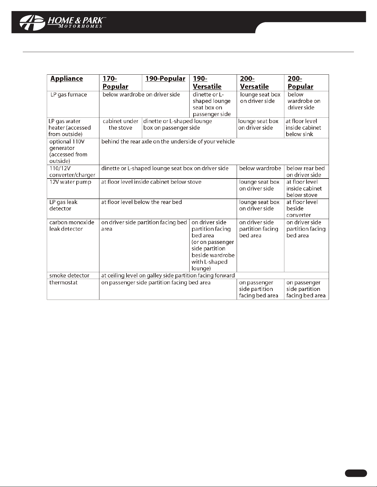
APPLIANCE LOCATION
DAILY LIVING
DDoocc NNoo::
MNSA0006 Rev: 00
CCooppyyrriigghhtt©© HHaannmmaarr MMoottoorr CCoorrppoorraattiioonn 22000033 CC--11
Page 19

DAILY LIVING
DDoocc NNoo::
MNSA0006 Rev: 00
CCooppyyrriigghhtt©© HHaannmmaarr MMoottoorr CCoorrppoorraattiioonn 22000033 DD--11
WASHROOM AND PRIVACY AREA:
PRIVACY DOORS (170-POPULAR, 190-POPULAR AND 200-POPULAR )
When privacy is required:
i) Open the door on the suspended cupboard located in the bed area of your vehicle.
ii) Release the plastic turn tab that secures the inner door, extend this door until privacy is achieved.
iii) Ensure TV cabinet door is lowered and secure privacy door to TV cabinet door with plastic tab.
iv) If desired, hang the curtains from the Velcro located on the lower edges of this door to maintain
complete privacy.
v) For 170 & 190 models, depress the finger catch located on the right edge on the left privacy door and
open the door. For 200 Popular model, lift handle to open water closet door and extend inner privacy
door until privacy is achieved
vi) Secure the door to the galley partition wall using the strap.
PRIVACY DOORS (190-VERSATILE)
When privacy is required:
i) Open both privacy doors until they are parallel with the galley partitions.
ii) Release the plastic turn tabs that secure the inner doors and extend these doors until privacy is achieved.
iii) The doors can be secured in this position by the plastic turn tabs located on the galley partitions.
iv) Complete privacy can now be achieved by closing the curtain at the galley window.
v) If desired, the privacy doors can be extended from the outside and secured using the plastic turn tabs
located on the inner doors.
When the privacy doors are returned to a closed position, ensure they are secured to prevent the doors from
opening while traveling.
PRIVACY DOORS (200-VERSATILE)
When privacy is required:
i) To open the front privacy door, depress the latch located to the left of the towel bar.
ii) Extend the door to the front galley partition while keeping the mirror facing to the rear of the vehicle.
iii) To secure the door in place,rest the doors edge in front of the upper galley cabinet door.
iv) Open the rear privacy door until it is parallel with the rear refrigerator partition.
v) Release the plastic turn tab that secures the inner door and extend the door until privacy is achieved.
vi) To secure the rear privacy door in place,slide the upper door extension so that it rests between the
upper cabinet doors.
vii) Complete privacy can now be achieved by closing the curtain at the galley window.
To close the front privacy door, depress the latch located to the right of the towel bar and fold the doors
together before closing. When the privacy doors are returned to a closed position, ensure they are secured to
prevent the doors from opening while traveling.
DAILY LIVING
DDoocc NNoo::
MNSA0006 Rev: 00
CCooppyyrriigghhtt©© HHaannmmaarr MMoottoorr CCoorrppoorraattiioonn 22000033 DD--11
WASHROOM AND PRIVACY AREA:
PRIVACY DOORS (170-POPULAR, 190-POPULAR AND 200-POPULAR )
When privacy is required:
i) Open the door on the suspended cupboard located in the bed area of your vehicle.
ii) Release the plastic turn tab that secures the inner door, extend this door until privacy is achieved.
iii) Ensure TV cabinet door is lowered and secure privacy door to TV cabinet door with plastic tab.
iv) If desired, hang the curtains from the Velcro located on the lower edges of this door to maintain
complete privacy.
v) For 170 & 190 models, depress the finger catch located on the right edge on the left privacy door and
open the door. For 200 Popular model, lift handle to open water closet door and extend inner privacy
door until privacy is achieved
vi) Secure the door to the galley partition wall using the strap.
PRIVACY DOORS (190-VERSATILE)
When privacy is required:
i) Open both privacy doors until they are parallel with the galley partitions.
ii) Release the plastic turn tabs that secure the inner doors and extend these doors until privacy is achieved.
iii) The doors can be secured in this position by the plastic turn tabs located on the galley partitions.
iv) Complete privacy can now be achieved by closing the curtain at the galley window.
v) If desired, the privacy doors can be extended from the outside and secured using the plastic turn tabs
located on the inner doors.
When the privacy doors are returned to a closed position, ensure they are secured to prevent the doors from
opening while traveling.
PRIVACY DOORS (200-VERSATILE)
When privacy is required:
i) To open the front privacy door, depress the latch located to the left of the towel bar.
ii) Extend the door to the front galley partition while keeping the mirror facing to the rear of the vehicle.
iii) To secure the door in place,rest the doors edge in front of the upper galley cabinet door.
iv) Open the rear privacy door until it is parallel with the rear refrigerator partition.
v) Release the plastic turn tab that secures the inner door and extend the door until privacy is achieved.
vi) To secure the rear privacy door in place,slide the upper door extension so that it rests between the
upper cabinet doors.
vii) Complete privacy can now be achieved by closing the curtain at the galley window.
To close the front privacy door, depress the latch located to the right of the towel bar and fold the doors
together before closing. When the privacy doors are returned to a closed position, ensure they are secured to
prevent the doors from opening while traveling.
Page 20

DAILY LIVING
DDoocc NNoo::
MNSA0006 Rev: 00
CCooppyyrriigghhtt©© HHaannmmaarr MMoottoorr CCoorrppoorraattiioonn 22000033 DD--22
TOILET
See appropriate component Manufacturer's Owners Manual for operating instructions.
STAND-UP AISLE SHOWER
To set up the stand-up aisle shower:
i) If possible, park your vehicle sloping slightly to the rear to prevent water from running to the front of the
lowered floor while showering (otherwise, any excess water can be directed towards the drain with a
towel).
ii) Extend all privacy doors (see Privacy Doors D-1).
iii) Remove drain plug from floor.
iv) Release the Velcro retention straps and place the hand held shower head in the holder on the shelf.
v) Draw the shower curtain until you are completely surrounded.
vi) Using the Velcro connectors,secure the edges of the curtain together allowing the shower hose to hang
within the shower area to retain any dripping water inside the curtains.
vii) When adjusting the water temperature, be sure to allow enough time for the temperature adjusted water
to exit the shower head before making further adjustments.
viii) To conserve water,discontinue the water flow at the shower head between wetting and rinsing.
To put away the stand-up shower:
i) Rinse and dry the shower curtain thoroughly (this function is most easily performed before leaving the
shower area after use).
ii) Allow the curtain to air dry completely this function can be expedited by operation the power roof vent.
iii) Follow the above instructions for stand-up shower set up in reverse order.
iv) Replace drain plug in floor when finished.
To prevent grey water tank contents from spilling onto the floor while driving,keep the drain plug
secured at all times.
DAILY LIVING
DDoocc NNoo::
MNSA0006 Rev: 00
CCooppyyrriigghhtt©© HHaannmmaarr MMoottoorr CCoorrppoorraattiioonn 22000033 DD--22
TOILET
See appropriate component Manufacturer's Owners Manual for operating instructions.
STAND-UP AISLE SHOWER
To set up the stand-up aisle shower:
i) If possible, park your vehicle sloping slightly to the rear to prevent water from running to the front of the
lowered floor while showering (otherwise, any excess water can be directed towards the drain with a
towel).
ii) Extend all privacy doors (see Privacy Doors D-1).
iii) Remove drain plug from floor.
iv) Release the Velcro retention straps and place the hand held shower head in the holder on the shelf.
v) Draw the shower curtain until you are completely surrounded.
vi) Using the Velcro connectors,secure the edges of the curtain together allowing the shower hose to hang
within the shower area to retain any dripping water inside the curtains.
vii) When adjusting the water temperature, be sure to allow enough time for the temperature adjusted water
to exit the shower head before making further adjustments.
viii) To conserve water,discontinue the water flow at the shower head between wetting and rinsing.
To put away the stand-up shower:
i) Rinse and dry the shower curtain thoroughly (this function is most easily performed before leaving the
shower area after use).
ii) Allow the curtain to air dry completely this function can be expedited by operation the power roof vent.
iii) Follow the above instructions for stand-up shower set up in reverse order.
iv) Replace drain plug in floor when finished.
To prevent grey water tank contents from spilling onto the floor while driving,keep the drain plug
secured at all times.
Page 21

WATER SYSTEM
DDoocc NNoo::
MNSA0006 Rev: 00
CCooppyyrriigghhtt©© HHaannmmaarr MMoottoorr CCoorrppoorraattiioonn 22000033 EE--11
WATER SYSTEM
Your vehicle is equipped with a water system for either completely, self contained,or fully dependent use. It is not
equipped with a pressure regulator to compensate for varying water pressure levels. During self contained use,
caution should be taken so as to minimize water consumption. For example, water consumption can be reduced
while showering if you turn off the shower between wetting down and rinsing off.
To avoid damage due to road vibrations, be sure not to store heavy or sharp objects where they may come into contact
with either the water lines or water pump. Also, allow sufficient room around the pump for proper operation.
FRESH WATER TANK
On Dodge models, the fresh water tank can be filled through the gravity fill located in the rear door post for 190
models and in the driver door step well for 170 models. On Chevrolet models, the gravity fill is in the side entry
door step well. To fill the tank:
i) Open the door.
ii) Open the gravity fill cover (on some models).
iii) Remove the plug, insert the hose and fill the tank using moderate pressure (excessive pressure will result
in a back flow of water).
iv) When the tank is full, water will overflow through the air vent at the top of the tank onto the ground for
Dodge 190 models, and into the door step well of Chevrolet and Dodge 170 models.
On Dodge models, the fresh water tank can also be filled through the city water connection located behind the
large lockable access door integrated within the running boards on the driver side. On Chevrolet models, the city
water connection is integrated into the flare behind the driver side rear wheel. To fill the tank:
i) Connect a hose to the city water connection (see City Water Connection E-1).
ii) Open the valve located at the city water connection.
iii) Open the water source moderately.
iv) When the tank is full, water will overflow through the air vent at the top of the tank onto the ground for
Dodge models, and into the door step well of Chevrolet models.
v) Close valve.
CITY WATER CONNECTION
On Dodge models, the city water connection is located behind the large lockable access door integrated within the
running boards on the driver side. On Chevrolet models,it is integrated into the flare behind the driver side rear
wheel. To connect the water system to an outside source:
i) Ensure that the water pump is turned off.
ii) Be sure that all interior water outlets are closed to prevent spillage.
iii) Close the front tap at the city water connection to prevent the fresh water tank from being filled.
iv) Remove the city water connection cap and the white plug from the compartment floor below the city
water connection.
v) Run the hose through this opening and connect it to the city water connection.
vi) Open the city water source moderately to prevent excessive water force inside your vehicle. (To protect
your system from excessive pressure from water supply systems encountered in some areas, a water
pressure regulator should be used. Such a regulator is not supplied with your vehicle).
vii) Note that this connection bypasses the water pump and fresh water tank. Therefore, the use of these
items is not necessary when connected directly to an external water source.
To disconnect the city water connection:
i) Turn off the external water source.
ii) Open the sink faucet to relieve the pressure in the system (failure to do so may result in an unexpected shower).
iii) Remove the hose from the city water connection, replace the cap and replace the plug in the
compartment floor.
WATER SYSTEM
DDoocc NNoo::
MNSA0006 Rev: 00
CCooppyyrriigghhtt©© HHaannmmaarr MMoottoorr CCoorrppoorraattiioonn 22000033 EE--11
WATER SYSTEM
Your vehicle is equipped with a water system for either completely, self contained,or fully dependent use. It is not
equipped with a pressure regulator to compensate for varying water pressure levels. During self contained use,
caution should be taken so as to minimize water consumption. For example, water consumption can be reduced
while showering if you turn off the shower between wetting down and rinsing off.
To avoid damage due to road vibrations, be sure not to store heavy or sharp objects where they may come into contact
with either the water lines or water pump. Also, allow sufficient room around the pump for proper operation.
FRESH WATER TANK
On Dodge models, the fresh water tank can be filled through the gravity fill located in the rear door post for 190
models and in the driver door step well for 170 models. On Chevrolet models, the gravity fill is in the side entry
door step well. To fill the tank:
i) Open the door.
ii) Open the gravity fill cover (on some models).
iii) Remove the plug, insert the hose and fill the tank using moderate pressure (excessive pressure will result
in a back flow of water).
iv) When the tank is full, water will overflow through the air vent at the top of the tank onto the ground for
Dodge 190 models, and into the door step well of Chevrolet and Dodge 170 models.
On Dodge models, the fresh water tank can also be filled through the city water connection located behind the
large lockable access door integrated within the running boards on the driver side. On Chevrolet models, the city
water connection is integrated into the flare behind the driver side rear wheel. To fill the tank:
i) Connect a hose to the city water connection (see City Water Connection E-1).
ii) Open the valve located at the city water connection.
iii) Open the water source moderately.
iv) When the tank is full, water will overflow through the air vent at the top of the tank onto the ground for
Dodge models, and into the door step well of Chevrolet models.
v) Close valve.
CITY WATER CONNECTION
On Dodge models, the city water connection is located behind the large lockable access door integrated within the
running boards on the driver side. On Chevrolet models,it is integrated into the flare behind the driver side rear
wheel. To connect the water system to an outside source:
i) Ensure that the water pump is turned off.
ii) Be sure that all interior water outlets are closed to prevent spillage.
iii) Close the front tap at the city water connection to prevent the fresh water tank from being filled.
iv) Remove the city water connection cap and the white plug from the compartment floor below the city
water connection.
v) Run the hose through this opening and connect it to the city water connection.
vi) Open the city water source moderately to prevent excessive water force inside your vehicle. (To protect
your system from excessive pressure from water supply systems encountered in some areas, a water
pressure regulator should be used. Such a regulator is not supplied with your vehicle).
vii) Note that this connection bypasses the water pump and fresh water tank. Therefore, the use of these
items is not necessary when connected directly to an external water source.
To disconnect the city water connection:
i) Turn off the external water source.
ii) Open the sink faucet to relieve the pressure in the system (failure to do so may result in an unexpected shower).
iii) Remove the hose from the city water connection, replace the cap and replace the plug in the
compartment floor.
Page 22
WATER SYSTEM
DDoocc NNoo::
MNSA0006 Rev: 00
CCooppyyrriigghhtt©© HHaannmmaarr MMoottoorr CCoorrppoorraattiioonn 22000033 EE--22
WASTE WATER STORAGE AND DUMPING SYSTEM
Your vehicle is equipped with a waste water storage and dumping system that will provide adequate and effective
storage and dumping of waste water. Your vehicle should be as level as possible to allow optimal operation of the
system.
CAUTION: Ensure that both the black and grey water gate valves, located behind the small access door below the
driver step well, are closed (inward position) before using the waste water system. This applies especially after
extensive driving.
Waste Tank Preparation
Your vehicle is equipped with two waste water tanks; the grey water tank is for waste water from the sink and aisle
shower and the black water tank is for sewage from the toilet. Both tanks are equipped with separate dump valves
so that each may be dumped independently. Before use of either waste tank, be sure to read instructions provided
by the toilet manufacturer regarding waste water chemicals. We suggest that such chemicals be used every time
to minimize build up of solids on water level sensors inside the tanks.
Waste Tank Dumping
Waste water tank contents must be dumped in authorized facilities only. To completely clear the waste water tanks
of all solid material, tanks should be full to provide the necessary volume required for complete dumping. If you
wish to dump a partially full tank, it is advisable to fill the remaining volume with water first. Also, to completely
clear the tanks of all solid material, tanks should be dumped immediately after road travel while tank contents are
unsettled.
To dump the black water tank:
i) Ensure that the lower "T" shaped black water gate valve handle is closed (inward position).
ii) Remove the small cap located on the front of the sewage hose assembly and swing the support arm so
that the assembly can be pulled out.
iii) Remove the assembly cover.
iv) Connect the dump fitting (stored in the storage compartment behind the large access door) to the end
of the assembly.
v) Securely place the dump fitting and assembly in the local waste receptacle.
vi) Pull the black water gate valve handle to dump the tank contents.
vii) Once the tank is empty,close the gate valve, remove the fitting, return the assembly to its support
structure and ensure that all caps and supports are securely in place.
To dump the grey water tank:
i) Follow the same procedure using the inner grey water gate valve handle located above the black water
gate valve handle.
ii) Be sure to dump the grey water tank last so as to help flush out any solid waste in the sewage hose from
the black water tank.
iii) If desired, flush both waste tanks after dumping.
WATER SYSTEM
DDoocc NNoo::
MNSA0006 Rev: 00
CCooppyyrriigghhtt©© HHaannmmaarr MMoottoorr CCoorrppoorraattiioonn 22000033 EE--22
WASTE WATER STORAGE AND DUMPING SYSTEM
Your vehicle is equipped with a waste water storage and dumping system that will provide adequate and effective
storage and dumping of waste water. Your vehicle should be as level as possible to allow optimal operation of the
system.
CAUTION: Ensure that both the black and grey water gate valves, located behind the small access door below the
driver step well, are closed (inward position) before using the waste water system. This applies especially after
extensive driving.
Waste Tank Preparation
Your vehicle is equipped with two waste water tanks; the grey water tank is for waste water from the sink and aisle
shower and the black water tank is for sewage from the toilet. Both tanks are equipped with separate dump valves
so that each may be dumped independently. Before use of either waste tank, be sure to read instructions provided
by the toilet manufacturer regarding waste water chemicals. We suggest that such chemicals be used every time
to minimize build up of solids on water level sensors inside the tanks.
Waste Tank Dumping
Waste water tank contents must be dumped in authorized facilities only. To completely clear the waste water tanks
of all solid material, tanks should be full to provide the necessary volume required for complete dumping. If you
wish to dump a partially full tank, it is advisable to fill the remaining volume with water first. Also, to completely
clear the tanks of all solid material, tanks should be dumped immediately after road travel while tank contents are
unsettled.
To dump the black water tank:
i) Ensure that the lower "T" shaped black water gate valve handle is closed (inward position).
ii) Remove the small cap located on the front of the sewage hose assembly and swing the support arm so
that the assembly can be pulled out.
iii) Remove the assembly cover.
iv) Connect the dump fitting (stored in the storage compartment behind the large access door) to the end
of the assembly.
v) Securely place the dump fitting and assembly in the local waste receptacle.
vi) Pull the black water gate valve handle to dump the tank contents.
vii) Once the tank is empty,close the gate valve, remove the fitting, return the assembly to its support
structure and ensure that all caps and supports are securely in place.
To dump the grey water tank:
i) Follow the same procedure using the inner grey water gate valve handle located above the black water
gate valve handle.
ii) Be sure to dump the grey water tank last so as to help flush out any solid waste in the sewage hose from
the black water tank.
iii) If desired, flush both waste tanks after dumping.
Page 23
WATER SYSTEM
DDoocc NNoo::
MNSA0006 Rev: 00
CCooppyyrriigghhtt©© HHaannmmaarr MMoottoorr CCoorrppoorraattiioonn 22000033 EE--33
Waste Tank Flushing
To flush the waste water tanks:
i) Ensure that both tanks are empty.
ii) Fill the black water tank by inserting a hose into the toilet and the grey water tank using the sink.
iii) Dump both tanks.
Both waste water tanks can be flushed using a similar procedure, but rather than filling each tank using the
potable water system, they can be filled by inserting a hose directly into the sink or toilet.
POTABLE WATER SYSTEM DRAINING
To completely drain the fresh water system of all water:
i) Ensure that the water pump is off and that your vehicle is level.
ii) Drain the fresh water tank and the hot and cold fresh water system by removing the threaded cap at the
low point drain. This drain is on the fresh water tank behind driver rear wheel of Dodge models. It is
attached to the sewage hose assembly behind the small access door directly below the driver step well
of Chevrolet models.
iii) If your vehicle is equipped with an optional water heater, follow manufacturer's draining instructions.
iv) Open the sink faucet and turn on the water pump until water is no longer pumped.
v) Turn off the water pump.
vi) Open all water outlets including the sink faucet,aisle shower faucet (if equipped), external shower faucet, and
toilet flushing pedal. The latter can be propped open or opened manually several times. This procedure
allows gravity to draw any remaining water out through the tank and city water connection drains.
vii) Disconnect and drain the P-traps of the sink and aisle shower (if equipped). (Shower P-trap is located on
your vehicle underside to the rear of the waste water tanks.)
If this procedure is followed, it is unnecessary to blow out the water system. Once the system is drained, be
sure to close all taps before driving.
POTABLE WATER SYSTEM SANITIZING
Your potable water system should be sanitized if it is new,has not been used for a period of time, or may have
become contaminated.
To sanitize your system:
i) Prepare a chlorine solution using 4 L (1 gallon) of water and 60 ml (1/4 cup) of household bleach (5%
sodium hypo chlorite solution).
ii) With the fresh water tank empty, pour 4 L (1 gallon) of solution into the tank for each 60 L (15 gallon) of
tank capacity. (As an alternative, several commercial solutions are available and should be used as
directed on the package).
iii) Complete filling of the tank with fresh water.
iv) Turn on the water pump and slowly open all faucets to release trapped air.
v) Allow to stand for 3 hours then drain and flush with fresh potable water.
vi) To remove excessive chlorine taste or odor which may remain, prepare a solution of 1 L (1 quart) vinegar
to 20 L (5 gallons) water and pour into tank and allow solution to agitate in tank by vehicle motion
(several days if possible).
vii) Drain tank and flush with fresh potable water.
WATER SYSTEM
DDoocc NNoo::
MNSA0006 Rev: 00
CCooppyyrriigghhtt©© HHaannmmaarr MMoottoorr CCoorrppoorraattiioonn 22000033 EE--33
Waste Tank Flushing
To flush the waste water tanks:
i) Ensure that both tanks are empty.
ii) Fill the black water tank by inserting a hose into the toilet and the grey water tank using the sink.
iii) Dump both tanks.
Both waste water tanks can be flushed using a similar procedure, but rather than filling each tank using the
potable water system, they can be filled by inserting a hose directly into the sink or toilet.
POTABLE WATER SYSTEM DRAINING
To completely drain the fresh water system of all water:
i) Ensure that the water pump is off and that your vehicle is level.
ii) Drain the fresh water tank and the hot and cold fresh water system by removing the threaded cap at the
low point drain. This drain is on the fresh water tank behind driver rear wheel of Dodge models. It is
attached to the sewage hose assembly behind the small access door directly below the driver step well
of Chevrolet models.
iii) If your vehicle is equipped with an optional water heater, follow manufacturer's draining instructions.
iv) Open the sink faucet and turn on the water pump until water is no longer pumped.
v) Turn off the water pump.
vi) Open all water outlets including the sink faucet,aisle shower faucet (if equipped), external shower faucet, and
toilet flushing pedal. The latter can be propped open or opened manually several times. This procedure
allows gravity to draw any remaining water out through the tank and city water connection drains.
vii) Disconnect and drain the P-traps of the sink and aisle shower (if equipped). (Shower P-trap is located on
your vehicle underside to the rear of the waste water tanks.)
If this procedure is followed, it is unnecessary to blow out the water system. Once the system is drained, be
sure to close all taps before driving.
POTABLE WATER SYSTEM SANITIZING
Your potable water system should be sanitized if it is new,has not been used for a period of time, or may have
become contaminated.
To sanitize your system:
i) Prepare a chlorine solution using 4 L (1 gallon) of water and 60 ml (1/4 cup) of household bleach (5%
sodium hypo chlorite solution).
ii) With the fresh water tank empty, pour 4 L (1 gallon) of solution into the tank for each 60 L (15 gallon) of
tank capacity. (As an alternative, several commercial solutions are available and should be used as
directed on the package).
iii) Complete filling of the tank with fresh water.
iv) Turn on the water pump and slowly open all faucets to release trapped air.
v) Allow to stand for 3 hours then drain and flush with fresh potable water.
vi) To remove excessive chlorine taste or odor which may remain, prepare a solution of 1 L (1 quart) vinegar
to 20 L (5 gallons) water and pour into tank and allow solution to agitate in tank by vehicle motion
(several days if possible).
vii) Drain tank and flush with fresh potable water.
Page 24
WATER SYSTEM
DDoocc NNoo::
MNSA0006 Rev: 00
CCooppyyrriigghhtt©© HHaannmmaarr MMoottoorr CCoorrppoorraattiioonn 22000033 EE--44
POTABLE WATER SYSTEM WINTERIZING
To winterize your potable water system:
i) Drain the entire system.
ii) Add 2 L (1/2 gallon) of approved nontoxic recreational vehicle antifreeze to the fresh water tank using
the gravity fill. Close water heater bypass valves to avoid filling the water heater storage tank with
antifreeze. Otherwise, use 25 L (6.5 gallons) of antifreeze.
iii) Turn on the water pump.
iv) Open both faucets until antifreeze is visible.
v) Open the toilet valve until antifreeze is visible.
vi) Turn off pump.
To prepare your potable water system for use:
i) Drain the antifreeze from the system.
ii) Sanitize the system if desired.
iii) Fill the system with water.
iv) Open bypass valves.
WATER HEATER BYPASS
To activate the water heater bypass:
i) Drain the entire system.
ii) Turn the brass valves located on the interior front of the water heater to the closed position.
WINTER USE
We recommend that you do not use the water system during freezing weather and ensure that it is properly
drained or winterized before the temperature falls below freezing.
If use of the water system is necessary under freezing conditions, use portable water containers and antifreeze in
the waste water tanks. Be sure to use an approved nontoxic recreational vehicle antifreeze and follow the
manufacturer's instructions carefully to ensure that damage to the system will not occur.
WATER SYSTEM
DDoocc NNoo::
MNSA0006 Rev: 00
CCooppyyrriigghhtt©© HHaannmmaarr MMoottoorr CCoorrppoorraattiioonn 22000033 EE--44
POTABLE WATER SYSTEM WINTERIZING
To winterize your potable water system:
i) Drain the entire system.
ii) Add 2 L (1/2 gallon) of approved nontoxic recreational vehicle antifreeze to the fresh water tank using
the gravity fill. Close water heater bypass valves to avoid filling the water heater storage tank with
antifreeze. Otherwise, use 25 L (6.5 gallons) of antifreeze.
iii) Turn on the water pump.
iv) Open both faucets until antifreeze is visible.
v) Open the toilet valve until antifreeze is visible.
vi) Turn off pump.
To prepare your potable water system for use:
i) Drain the antifreeze from the system.
ii) Sanitize the system if desired.
iii) Fill the system with water.
iv) Open bypass valves.
WATER HEATER BYPASS
To activate the water heater bypass:
i) Drain the entire system.
ii) Turn the brass valves located on the interior front of the water heater to the closed position.
WINTER USE
We recommend that you do not use the water system during freezing weather and ensure that it is properly
drained or winterized before the temperature falls below freezing.
If use of the water system is necessary under freezing conditions, use portable water containers and antifreeze in
the waste water tanks. Be sure to use an approved nontoxic recreational vehicle antifreeze and follow the
manufacturer's instructions carefully to ensure that damage to the system will not occur.
Page 25

ELECTRICAL SYSTEM
DDoocc NNoo::
MNSA0006 Rev: 00
CCooppyyrriigghhtt©© HHaannmmaarr MMoottoorr CCoorrppoorraattiioonn 22000033 FF--11
Your vehicle's electrical system should not be subjected to changes and/or additions to circuitry, appliances, etc.
without consulting your dealer for proper installation procedures.
110/12V CONVERTER/CHARGER
For your convenience when camping in parks with hookups for 110V power all our models have in the electrical
system a 110/12V converter/charger. The converter reduces the voltage from 110V to 12V and distributes the
power to all 12V house appliances and lights as well as it recharges all batteries present in the system. The
converter/charger is incorporated in the main electrical distribution panel with all 110V and 12V breakers. See
section C.0. for convertor/charger location. To open the access door to the converter, twist the square locking knob
1/4 turn and pull open. All breakers/circuits are identified on the panel. See 110/12V converter/charger
Manufacturer's Owner's Manuals for operating instructions.
NOTICE: In the event that your refrigerator stops cooling while being operated by 120 volt AC (Chevrolet only),and the
corresponding breaker is not tripped,check the GFCI receptacle located in the driver side lounge box, and reset if tripped.
EXTERNAL ELECTRICAL SOURCE CONNECTION
Your vehicle is equipped with a heavy duty 30 amp. power cord so that you can connect your electrical system to
an outside 110V (in Canada) or 120V (in U.S.) power source. On Dodge models, the power cord is stored in the
storage compartment located behind the large lockable access door integrated within the running boards on the
driver side. On Chevrolet models, it is integrated into the flare behind the driver side rear wheel. A 30 to 15 amp.
adapter is not included with your vehicle.
Notice: When connecting your system to an outside source, ensure that a properly equipped (three
pronged) and functioning receptacle is used. If any type of spark or shock is detected, disconnect from the
source immediately and do not reconnect until the problem is corrected.
GENERATOR (OPTIONAL)
All service requirements are listed in the Generator Owners Manual.
The generator is located and accessed on the underside behind the rear axle of your vehicle.
CAUTION: When launching a boat, generators are not to be submerged in water. This will permanently
damage the generator. If you cannot launch without submerging the generator, an alternate method is to use a
boat launching service.
BUILT-IN 110V AIR CONDITIONER
In addition to the operating instructions contained in the Manufacturer's Owner's Manual, the air conditioner
should be started as follows when the optional generator is used:
i) Start the generator and operate for several minutes until warm.
ii) Ensure the thermostat is set at its warmest setting (1).
iii) Turn air conditioner master control to "low cool" position.
iv) Adjust the thermostat cooler (towards "8") until the compressor starts.
v) Once the compressor is running, adjust master control and thermostat to desired settings.
Your vehicle should be parked as close to level as possible to maximize the air conditioner's efficiency. In a
humid environment some water will condense when the air is blown through the cold side of the air
conditioner. The water accumulates in a pan under the air conditioner and drains away at the back of the
van. From time to time water may spill from the front of the air conditioner during abrupt stops or while
parked on a steep forward slope.
ELECTRICAL SYSTEM
DDoocc NNoo::
MNSA0006 Rev: 00
CCooppyyrriigghhtt©© HHaannmmaarr MMoottoorr CCoorrppoorraattiioonn 22000033 FF--11
Your vehicle's electrical system should not be subjected to changes and/or additions to circuitry, appliances, etc.
without consulting your dealer for proper installation procedures.
110/12V CONVERTER/CHARGER
For your convenience when camping in parks with hookups for 110V power all our models have in the electrical
system a 110/12V converter/charger. The converter reduces the voltage from 110V to 12V and distributes the
power to all 12V house appliances and lights as well as it recharges all batteries present in the system. The
converter/charger is incorporated in the main electrical distribution panel with all 110V and 12V breakers. See
section C.0. for convertor/charger location. To open the access door to the converter, twist the square locking knob
1/4 turn and pull open. All breakers/circuits are identified on the panel. See 110/12V converter/charger
Manufacturer's Owner's Manuals for operating instructions.
NOTICE: In the event that your refrigerator stops cooling while being operated by 120 volt AC (Chevrolet only),and the
corresponding breaker is not tripped,check the GFCI receptacle located in the driver side lounge box, and reset if tripped.
EXTERNAL ELECTRICAL SOURCE CONNECTION
Your vehicle is equipped with a heavy duty 30 amp. power cord so that you can connect your electrical system to
an outside 110V (in Canada) or 120V (in U.S.) power source. On Dodge models, the power cord is stored in the
storage compartment located behind the large lockable access door integrated within the running boards on the
driver side. On Chevrolet models, it is integrated into the flare behind the driver side rear wheel. A 30 to 15 amp.
adapter is not included with your vehicle.
Notice: When connecting your system to an outside source, ensure that a properly equipped (three
pronged) and functioning receptacle is used. If any type of spark or shock is detected, disconnect from the
source immediately and do not reconnect until the problem is corrected.
GENERATOR (OPTIONAL)
All service requirements are listed in the Generator Owners Manual.
The generator is located and accessed on the underside behind the rear axle of your vehicle.
CAUTION: When launching a boat, generators are not to be submerged in water. This will permanently
damage the generator. If you cannot launch without submerging the generator, an alternate method is to use a
boat launching service.
BUILT-IN 110V AIR CONDITIONER
In addition to the operating instructions contained in the Manufacturer's Owner's Manual, the air conditioner
should be started as follows when the optional generator is used:
i) Start the generator and operate for several minutes until warm.
ii) Ensure the thermostat is set at its warmest setting (1).
iii) Turn air conditioner master control to "low cool" position.
iv) Adjust the thermostat cooler (towards "8") until the compressor starts.
v) Once the compressor is running, adjust master control and thermostat to desired settings.
Your vehicle should be parked as close to level as possible to maximize the air conditioner's efficiency. In a
humid environment some water will condense when the air is blown through the cold side of the air
conditioner. The water accumulates in a pan under the air conditioner and drains away at the back of the
van. From time to time water may spill from the front of the air conditioner during abrupt stops or while
parked on a steep forward slope.
Page 26

ELECTRICAL SYSTEM
DDoocc NNoo::
MNSA0006 Rev: 00
CCooppyyrriigghhtt©© HHaannmmaarr MMoottoorr CCoorrppoorraattiioonn 22000033 FF--22
MONITOR PANEL
A monitor panel, located on the front closet partition above the passenger lounge seat, is provided to monitor the
approximate fluid levels in the fresh, grey and black water tanks, LP gas tank (Dodge models only), and charge level
in the auxiliary battery.
Regarding the water tank levels, be aware that the panel does not always reflect actual fluid levels. For example,
when the 1/3 level light is on, the tank may be anywhere from 1/3 to just under 2/3 full. Or when the panel reads
empty,the tank may be anywhere from empty to just under 1/3 full.
If you do not regularly use a sanitation fluid in your black and grey water tanks, the tanks must be flushed
periodically with sanitation fluid to prevent the accumulation of solids on the probes so as to maintain accurate
black and grey water level readings. To flush:
i) If necessary, dump the black and grey water tanks (see E.3.).
ii) Add 20 L (5 gallons) of a water and sanitation fluid solution mixed as recommended by the fluid
manufacturer.
iii) Drive your vehicle until numerous stops, starts and turns have been achieved.
iv) Dump and flush the black and grey water tanks (see E.3.).
The auxiliary battery charge level indicator is marked "C", "G","F", and "L". "C" indicates the battery is fully charged. "G"
means the battery charge is "good", "F" indicates "fair", and "L" indicates "low". Note that the battery condition is
indicated by the uppermost light that is on. For example, if the "G","F", and "L" lights are on,the battery charge is "Good".
The panel also provides the switch from the water pump and a disconnect switch for the auxiliary battery.
AUXILIARY BATTERY AND ISOLATOR
The auxiliary battery is a deep-cycle maintenance free gel battery. Do not add water. This battery is located at the
rear driver side below the floor on all models except the 170-Popular where it is on the passenger side. On Dodge
models, it can be accessed from the rear cargo door by lifting the carpet liner and removing the hatch cover. On
Chevrolet models, the auxiliary battery can be accessed from the underside of the vehicle.
On Dodge models, the battery isolator is located near the fire wall under the hood. On Chevrolet models, it is
located on the inboard passenger side of the frame below the engine.
The auxiliary battery is automatically charged through the isolator by the engine's alternator while the engine is
running. This battery is also automatically charged by the converter/charger when:
i) Your vehicle is connected to an outside electrical power source.
ii) The breakers in the converter/charger are in the "ON" position.
iii) The battery disconnect switch on the monitor panel is set to the "ON" position prior to connection to an
outside electrical power source.
iv) Or while the generator is in operation (if so equipped).
A disconnect switch, located on the monitor panel, provides a disconnect for the auxiliary battery from the 12V
system while your vehicle is not in use.
Since the auxiliary battery is deep-cycle, it may be discharged completely and recharged without damage (whereas
the automotive battery is designed to be kept fully charged by the alternator and may undergo damage if fully
discharged). However, a fully discharged battery should never remain in this dead state and should be recharged
immediately to prevent damage. When not in use, the auxiliary battery will slowly discharge on its own. Accordingly,
if the battery is not being used, it should be recharged every month by connecting to an outside electrical power
source, by operating the generator (if equipped) for at least 12 hours, or by running your vehicle's engine.
The isolator is located under the hood in the engine compartment. The isolator allows the alternator to charge
both the automotive and auxiliary batteries when the engine is running. However, it will prevent your vehicle's 12V
motorhome equipment (interior lights, water pump, exhaust fans, furnace blower, etc.) from drawing on the
automotive battery (through the auxiliary battery) while the engine is not running.
For a further explanation of the operation of the auxiliary battery and isolator, see the owner's manual for the
converter/charger.
ELECTRICAL SYSTEM
DDoocc NNoo::
MNSA0006 Rev: 00
CCooppyyrriigghhtt©© HHaannmmaarr MMoottoorr CCoorrppoorraattiioonn 22000033 FF--22
MONITOR PANEL
A monitor panel, located on the front closet partition above the passenger lounge seat, is provided to monitor the
approximate fluid levels in the fresh, grey and black water tanks, LP gas tank (Dodge models only), and charge level
in the auxiliary battery.
Regarding the water tank levels, be aware that the panel does not always reflect actual fluid levels. For example,
when the 1/3 level light is on, the tank may be anywhere from 1/3 to just under 2/3 full. Or when the panel reads
empty,the tank may be anywhere from empty to just under 1/3 full.
If you do not regularly use a sanitation fluid in your black and grey water tanks, the tanks must be flushed
periodically with sanitation fluid to prevent the accumulation of solids on the probes so as to maintain accurate
black and grey water level readings. To flush:
i) If necessary, dump the black and grey water tanks (see E.3.).
ii) Add 20 L (5 gallons) of a water and sanitation fluid solution mixed as recommended by the fluid
manufacturer.
iii) Drive your vehicle until numerous stops, starts and turns have been achieved.
iv) Dump and flush the black and grey water tanks (see E.3.).
The auxiliary battery charge level indicator is marked "C", "G","F", and "L". "C" indicates the battery is fully charged. "G"
means the battery charge is "good", "F" indicates "fair", and "L" indicates "low". Note that the battery condition is
indicated by the uppermost light that is on. For example, if the "G","F", and "L" lights are on,the battery charge is "Good".
The panel also provides the switch from the water pump and a disconnect switch for the auxiliary battery.
AUXILIARY BATTERY AND ISOLATOR
The auxiliary battery is a deep-cycle maintenance free gel battery. Do not add water. This battery is located at the
rear driver side below the floor on all models except the 170-Popular where it is on the passenger side. On Dodge
models, it can be accessed from the rear cargo door by lifting the carpet liner and removing the hatch cover. On
Chevrolet models, the auxiliary battery can be accessed from the underside of the vehicle.
On Dodge models, the battery isolator is located near the fire wall under the hood. On Chevrolet models, it is
located on the inboard passenger side of the frame below the engine.
The auxiliary battery is automatically charged through the isolator by the engine's alternator while the engine is
running. This battery is also automatically charged by the converter/charger when:
i) Your vehicle is connected to an outside electrical power source.
ii) The breakers in the converter/charger are in the "ON" position.
iii) The battery disconnect switch on the monitor panel is set to the "ON" position prior to connection to an
outside electrical power source.
iv) Or while the generator is in operation (if so equipped).
A disconnect switch, located on the monitor panel, provides a disconnect for the auxiliary battery from the 12V
system while your vehicle is not in use.
Since the auxiliary battery is deep-cycle, it may be discharged completely and recharged without damage (whereas
the automotive battery is designed to be kept fully charged by the alternator and may undergo damage if fully
discharged). However, a fully discharged battery should never remain in this dead state and should be recharged
immediately to prevent damage. When not in use, the auxiliary battery will slowly discharge on its own. Accordingly,
if the battery is not being used, it should be recharged every month by connecting to an outside electrical power
source, by operating the generator (if equipped) for at least 12 hours, or by running your vehicle's engine.
The isolator is located under the hood in the engine compartment. The isolator allows the alternator to charge
both the automotive and auxiliary batteries when the engine is running. However, it will prevent your vehicle's 12V
motorhome equipment (interior lights, water pump, exhaust fans, furnace blower, etc.) from drawing on the
automotive battery (through the auxiliary battery) while the engine is not running.
For a further explanation of the operation of the auxiliary battery and isolator, see the owner's manual for the
converter/charger.
Page 27

ELECTRICAL SYSTEM
DDoocc NNoo::
MNSA0006 Rev: 00
CCooppyyrriigghhtt©© HHaannmmaarr MMoottoorr CCoorrppoorraattiioonn 22000033 FF--33
AUTOMOTIVE BATTERY
The electronic radio in your vehicle will exert a small draw on the automotive battery to maintain the time and
preset stations. To prevent the battery from damage caused by being completely drained, the radio should be
disconnected from the automotive battery when your vehicle will not be driven for 2 months or more.
On Dodge models, the radio and courtesy lights can be disconnected by pulling the black 15 amp.fuse at the fuse
and relay compartment located on the driver side of the instrument panel. This compartment is accessible only
when the driver door is open.
For Chevrolet models,the radio can be disconnected by removing the 10 amp. radio fuse from the fuse block
located at the left underside of the dash, or by disconnecting the negative automotive battery cable.
INTERIOR CAB LIGHT AND IGNITION LIGHT
The interior 12V cab light located on the underside of the cabinet over the windshield (and the storage area light
below the optional rear L-shaped lounge of Dodge models) have a multipurpose switching system. This switching
system utilizes the switch on the light itself and the dash mounted headlight switch located to the left of the
steering wheel. These switches can be set for three types of use:
Driving
By turning the headlight switch to the center position and turning the cab light switch on, the cab light will turn on
when a door is open and turn off when all doors are closed. To turn on the cab light with doors closed, turn the
headlight switch all the way to the left (be aware that the ignition light will turn on also). This is similar to the
normal operation of the interior lights in a car.
Stationary Use (Doors Closed)
By turning the headlight switch all the way to the left, the cab light can be turned on and off using its own switch
with the doors closed (be aware that the ignition light will turn on also). This is similar to the normal operation of
the other interior lights in your vehicle except that the cab light and ignition light draw from the automotive
battery and not the auxiliary battery or converter/charger. Accordingly, excessive use may drain your automotive
battery!
Stationary Use (Doors Open)
On Dodge models, the cab light and ignition light will remain off with the doors open by turning the headlight
switch all the way to the right. To achieve the same result,do not leave the headlight switch in the center position
(as in F.8.a.) and turn off the cab light switch or you may drain your automotive battery.
On Chevrolet models, the cab light can be controlled by the light switch located on the dash to the left of the
steering column. The "dome override" can be used to turn off the cab light while the cab doors are open.
RANGE HOOD EXHAUST FAN
The range hood exhaust fan should be on while the L.P. gas stove is in operation. The range hood is equipped with
a damper control to reduce noise created by the damper flapping while driving and to reduce water entry while
washing your vehicle. The damper control is a steel loop, located at the front of the exhaust fan motor, and is
accessed from the underside of the range hood. To close the damper, push the control to the rear of your vehicle.
To open, pull the control to the front.
ELECTRICAL SYSTEM
DDoocc NNoo::
MNSA0006 Rev: 00
CCooppyyrriigghhtt©© HHaannmmaarr MMoottoorr CCoorrppoorraattiioonn 22000033 FF--33
AUTOMOTIVE BATTERY
The electronic radio in your vehicle will exert a small draw on the automotive battery to maintain the time and
preset stations. To prevent the battery from damage caused by being completely drained, the radio should be
disconnected from the automotive battery when your vehicle will not be driven for 2 months or more.
On Dodge models, the radio and courtesy lights can be disconnected by pulling the black 15 amp.fuse at the fuse
and relay compartment located on the driver side of the instrument panel. This compartment is accessible only
when the driver door is open.
For Chevrolet models,the radio can be disconnected by removing the 10 amp. radio fuse from the fuse block
located at the left underside of the dash, or by disconnecting the negative automotive battery cable.
INTERIOR CAB LIGHT AND IGNITION LIGHT
The interior 12V cab light located on the underside of the cabinet over the windshield (and the storage area light
below the optional rear L-shaped lounge of Dodge models) have a multipurpose switching system. This switching
system utilizes the switch on the light itself and the dash mounted headlight switch located to the left of the
steering wheel. These switches can be set for three types of use:
Driving
By turning the headlight switch to the center position and turning the cab light switch on, the cab light will turn on
when a door is open and turn off when all doors are closed. To turn on the cab light with doors closed, turn the
headlight switch all the way to the left (be aware that the ignition light will turn on also). This is similar to the
normal operation of the interior lights in a car.
Stationary Use (Doors Closed)
By turning the headlight switch all the way to the left, the cab light can be turned on and off using its own switch
with the doors closed (be aware that the ignition light will turn on also). This is similar to the normal operation of
the other interior lights in your vehicle except that the cab light and ignition light draw from the automotive
battery and not the auxiliary battery or converter/charger. Accordingly, excessive use may drain your automotive
battery!
Stationary Use (Doors Open)
On Dodge models, the cab light and ignition light will remain off with the doors open by turning the headlight
switch all the way to the right. To achieve the same result,do not leave the headlight switch in the center position
(as in F.8.a.) and turn off the cab light switch or you may drain your automotive battery.
On Chevrolet models, the cab light can be controlled by the light switch located on the dash to the left of the
steering column. The "dome override" can be used to turn off the cab light while the cab doors are open.
RANGE HOOD EXHAUST FAN
The range hood exhaust fan should be on while the L.P. gas stove is in operation. The range hood is equipped with
a damper control to reduce noise created by the damper flapping while driving and to reduce water entry while
washing your vehicle. The damper control is a steel loop, located at the front of the exhaust fan motor, and is
accessed from the underside of the range hood. To close the damper, push the control to the rear of your vehicle.
To open, pull the control to the front.
Page 28
L.P. GAS & SAFETY SYSTEM
DDoocc NNoo::
MNSA0006 Rev: 00
CCooppyyrriigghhtt©© HHaannmmaarr MMoottoorr CCoorrppoorraattiioonn 22000033 GG--11
Your vehicle is equipped with an L.P. gas system which, when properly handled and maintained, will provide
trouble and worry free operation of your L.P. gas fueled appliances.
L.P. fuel is stored in a liquid form under extremely high pressure. The L.P. gas tank is located on the vehicle
underside behind the rear axle. As fuel is used,L.P. gas passes from the top of the tank through the regulator into
the gas lines and eventually to the appliances.
Although the entire system has undergone extensive factory and dealer testing for leaks, the system's connections
and fittings are subjected to road vibrations and therefore should be checked annually for possible leaks.
L.P. gas is extremely flammable, colorless, heavier than air and smells like garlic or rotten eggs.
IF YOU SMELL GAS, extinguish any open flames, pilot lights and smoking materials immediately. Do not touch any
electrical switches. Shut off the gas supply at the tank valve (or at the valve located beside the gas fill on Dodges).
Open doors and windows to provide maximum ventilation. Leave the area until the odor clears. Have the system
checked and the leak corrected before use.
WAR NING : L.P. gas tanks shall not be placed or stored inside your vehicle. L.P. gas tanks are equipped with safety
devices which relieve excessive pressure by discharging gas to the atmosphere.
WAR NING : To reduce the danger of fire or explosion, do not store L.P. gas tanks,gasoline or other flammable
liquids inside your vehicle.
WAR NING : Ensure your purchase propane from a reputable propane facility. Contaminated propane is a common
source of system failure.
WAR NING : Follow all recommended maintenance schedules.
L.P. GAS TANK
To open and close the tank on Dodge and Chevy models, use the manual tank shutoff valve located on the tank.
It is recommended to close the manual tank shutoff valve when the vehicle is not in daily use or during travel.
Your refrigerator should be operated on 12V during travel and when the tank valve is closed.
APPLIANCES
WAR NING : It is not safe to use cooking appliances for space heating purposes.
The L.P. gas stove needs fresh air for its safe operation. Because the amount of oxygen supply is limited due to the
size of your vehicle, before operation of the L.P. gas stove, open the overhead vent or a window or turn on the
range hood exhaust fan (see F.8.). Proper ventilation when using the L.P. gas stove will reduce the dangers of
asphyxiation. It is especially important that the L.P. gas stove not be used for comfort heating purposes as the
danger of asphyxiation is greater when the appliance is used for long periods of time.
WAR NING : Portable fuel burning equipment, including wood and charcoal grills and stoves, shall not be used
inside your vehicle. Use of this equipment inside your vehicle may cause fire or asphyxiation.
See appropriate component Manufacturer's Owner's Manuals for operating instructions.
L.P. GAS & SAFETY SYSTEM
DDoocc NNoo::
MNSA0006 Rev: 00
CCooppyyrriigghhtt©© HHaannmmaarr MMoottoorr CCoorrppoorraattiioonn 22000033 GG--11
Your vehicle is equipped with an L.P. gas system which, when properly handled and maintained, will provide
trouble and worry free operation of your L.P. gas fueled appliances.
L.P. fuel is stored in a liquid form under extremely high pressure. The L.P. gas tank is located on the vehicle
underside behind the rear axle. As fuel is used,L.P. gas passes from the top of the tank through the regulator into
the gas lines and eventually to the appliances.
Although the entire system has undergone extensive factory and dealer testing for leaks, the system's connections
and fittings are subjected to road vibrations and therefore should be checked annually for possible leaks.
L.P. gas is extremely flammable, colorless, heavier than air and smells like garlic or rotten eggs.
IF YOU SMELL GAS, extinguish any open flames, pilot lights and smoking materials immediately. Do not touch any
electrical switches. Shut off the gas supply at the tank valve (or at the valve located beside the gas fill on Dodges).
Open doors and windows to provide maximum ventilation. Leave the area until the odor clears. Have the system
checked and the leak corrected before use.
WAR NING : L.P. gas tanks shall not be placed or stored inside your vehicle. L.P. gas tanks are equipped with safety
devices which relieve excessive pressure by discharging gas to the atmosphere.
WAR NING : To reduce the danger of fire or explosion, do not store L.P. gas tanks,gasoline or other flammable
liquids inside your vehicle.
WAR NING : Ensure your purchase propane from a reputable propane facility. Contaminated propane is a common
source of system failure.
WAR NING : Follow all recommended maintenance schedules.
L.P. GAS TANK
To open and close the tank on Dodge and Chevy models, use the manual tank shutoff valve located on the tank.
It is recommended to close the manual tank shutoff valve when the vehicle is not in daily use or during travel.
Your refrigerator should be operated on 12V during travel and when the tank valve is closed.
APPLIANCES
WAR NING : It is not safe to use cooking appliances for space heating purposes.
The L.P. gas stove needs fresh air for its safe operation. Because the amount of oxygen supply is limited due to the
size of your vehicle, before operation of the L.P. gas stove, open the overhead vent or a window or turn on the
range hood exhaust fan (see F.8.). Proper ventilation when using the L.P. gas stove will reduce the dangers of
asphyxiation. It is especially important that the L.P. gas stove not be used for comfort heating purposes as the
danger of asphyxiation is greater when the appliance is used for long periods of time.
WAR NING : Portable fuel burning equipment, including wood and charcoal grills and stoves, shall not be used
inside your vehicle. Use of this equipment inside your vehicle may cause fire or asphyxiation.
See appropriate component Manufacturer's Owner's Manuals for operating instructions.
Page 29
L.P. GAS & SAFETY SYSTEM
DDoocc NNoo::
MNSA0006 Rev: 00
CCooppyyrriigghhtt©© HHaannmmaarr MMoottoorr CCoorrppoorraattiioonn 22000033 GG--22
REFUELING PROCEDURES
WAR NING : Do not refuel L.P. gas tank to more than 80% of capacity.
A properly refueled L.P. gas tank will contain approximately 80% of its volume as liquid L.P. gas. Over fueling of the
L.P. gas tank can result in uncontrolled gas flow which can cause fire or explosion.
WARNING:The tank valve must be closed and ALL PILOT LIGHTS, APPLIANCES,AND THEIR IGNITERS (see
Operating Instructions) SHALL BE TURNED OFF during refueling of motor fuel tank and/or L.P. gas tank.
Only qualified personnel should refuel your L.P. gas tank.
Note: Appliance igniters may be individually turned off OR use the auxiliary battery disconnect switch located on
the monitor panel.
REGULATOR
On Dodge models, the L.P. gas regulator is located adjacent to the L.P. gas tank towards the front. On Chevrolet
models, it is adjacent to the L.P. gas tank towards the rear. This regulator has been installed in a protective cover to
keep out debris, and with the diaphragm vent facing downward. Ensure that the regulator vent always faces
downward to minimize vent blockage which could result in excessive gas pressure causing fire or explosion.
L.P. GAS LEAK DETECTOR
Your vehicle has been equipped with a L.P. gas leak detection device for your protection. See section C-1 for L.P.
gas leak detector location.
Be sure the detector is operating while using your vehicle. Do not block air circulation in the area where the L.P.
gas leak detector is located.
See Manufacturer's Owner's Manual for operating instructions.
CARBON MONOXIDE LEAK DETECTOR
Your vehicle has been equipped with a carbon monoxide (CO) leak detection device for your protection.
See section C-1 for carbon monoxide gas leak detector location.
Be sure the detector is operating while using your vehicle. Do not block air circulation in the area where the
carbon monoxide gas leak detector is located. See Manufacturer's Owner's Manual for operating instructions.
SMOKE DETECTOR
Your vehicle has been equipped with a smoke detection device for your protection.
See section C-1 for smoke detector location.
This device should be tested after each time your vehicle has been in storage,before each use, and at least once
each week during your vehicle's use. (Upon delivery of your vehicle from the factory,the detector is inoperative
because the battery is reversed to prevent drainage. Before operation, reverse the battery to the proper position
and test the operation of the detector).
Be sure the detector is operating while using your vehicle. Do not block air circulation in the area where the smoke
detector is located. See Manufacturer's Owner's Manual for operating instructions.
L.P. GAS & SAFETY SYSTEM
DDoocc NNoo::
MNSA0006 Rev: 00
CCooppyyrriigghhtt©© HHaannmmaarr MMoottoorr CCoorrppoorraattiioonn 22000033 GG--22
REFUELING PROCEDURES
WAR NING : Do not refuel L.P. gas tank to more than 80% of capacity.
A properly refueled L.P. gas tank will contain approximately 80% of its volume as liquid L.P. gas. Over fueling of the
L.P. gas tank can result in uncontrolled gas flow which can cause fire or explosion.
WARNING:The tank valve must be closed and ALL PILOT LIGHTS, APPLIANCES,AND THEIR IGNITERS (see
Operating Instructions) SHALL BE TURNED OFF during refueling of motor fuel tank and/or L.P. gas tank.
Only qualified personnel should refuel your L.P. gas tank.
Note: Appliance igniters may be individually turned off OR use the auxiliary battery disconnect switch located on
the monitor panel.
REGULATOR
On Dodge models, the L.P. gas regulator is located adjacent to the L.P. gas tank towards the front. On Chevrolet
models, it is adjacent to the L.P. gas tank towards the rear. This regulator has been installed in a protective cover to
keep out debris, and with the diaphragm vent facing downward. Ensure that the regulator vent always faces
downward to minimize vent blockage which could result in excessive gas pressure causing fire or explosion.
L.P. GAS LEAK DETECTOR
Your vehicle has been equipped with a L.P. gas leak detection device for your protection. See section C-1 for L.P.
gas leak detector location.
Be sure the detector is operating while using your vehicle. Do not block air circulation in the area where the L.P.
gas leak detector is located.
See Manufacturer's Owner's Manual for operating instructions.
CARBON MONOXIDE LEAK DETECTOR
Your vehicle has been equipped with a carbon monoxide (CO) leak detection device for your protection.
See section C-1 for carbon monoxide gas leak detector location.
Be sure the detector is operating while using your vehicle. Do not block air circulation in the area where the
carbon monoxide gas leak detector is located. See Manufacturer's Owner's Manual for operating instructions.
SMOKE DETECTOR
Your vehicle has been equipped with a smoke detection device for your protection.
See section C-1 for smoke detector location.
This device should be tested after each time your vehicle has been in storage,before each use, and at least once
each week during your vehicle's use. (Upon delivery of your vehicle from the factory,the detector is inoperative
because the battery is reversed to prevent drainage. Before operation, reverse the battery to the proper position
and test the operation of the detector).
Be sure the detector is operating while using your vehicle. Do not block air circulation in the area where the smoke
detector is located. See Manufacturer's Owner's Manual for operating instructions.
Page 30

OWNER MAINTENANCE
DDoocc NNoo::
MNSA0006 Rev: 00
CCooppyyrriigghhtt©© HHaannmmaarr MMoottoorr CCoorrppoorraattiioonn 22000033 HH--11
FIBERGLASS MAINTENANCE:
To maintain the original appearance and finish, your vehicle's fiberglass running boards, roof and/or body must be
waxed at least annually. If deterioration,such as tarnishing or chalking, should occur, apply a mild rubbing
compound and wax to restore the original appearance.
EXTERIOR WASHING:
To prevent water from entering your vehicle, avoid spraying water directly into exterior vents or grills. Use care and
caution when using a power washer to prevent water leaks.Do not point power washer directly towards any door
openings, body seams,vent or automotive striping.
OTHER MAINTENANCE:
For necessary maintenance of other components and appliances,see their respective manufacturer's owner's
manuals for instructions.
WINTER STORAGE:
INSIDE YOUR VEHICLE:
Before winter storage:
1. Be sure to clean your vehicle thoroughly.Special emphasis should be given to the appliances, such as the
refrigerator.
2. Once cleaned, leave the refrigerator door propped open with the cutting board in the freezer
compartment to prevent the development of odors (insert a box of baking soda if desired).
3. Open a window slightly allowing sufficient air circulation to avoid the development of odors,
condensation and mildew.
4. To prevent sun rays from deteriorating and fading interior fabrics, cover all upholstered seats and
cushions. As a further precaution, close all drapes tightly.
5. Disconnect the auxiliary battery using the disconnect switch located in the monitor panel.
OUTSIDE YOUR VEHICLE:
Before winter storage:
1. Ensure that all waste water tanks have been dumped and flushed and that the entire potable water
system has been properly drained, refer to sections on Potable Water System Draining and Potable Water
System Winterizing.
2. Be sure to cover the external vents to the refrigerator, exhaust fan, furnace and air conditioner (if
equipped) with heavy plastic sheeting to prevent entry by rodents and insects.
3. To improve tire life and maintain performance, put your vehicle up on blocks.Also, cover all tires exposed
to sun light to prevent deterioration from ultraviolet rays.
4. Consult your automotive owner's manual or local automotive dealer regarding steps necessary to
prevent engine and chassis damage during long periods of storage in your particular region.
OWNER MAINTENANCE
DDoocc NNoo::
MNSA0006 Rev: 00
CCooppyyrriigghhtt©© HHaannmmaarr MMoottoorr CCoorrppoorraattiioonn 22000033 HH--11
FIBERGLASS MAINTENANCE:
To maintain the original appearance and finish, your vehicle's fiberglass running boards, roof and/or body must be
waxed at least annually. If deterioration,such as tarnishing or chalking, should occur, apply a mild rubbing
compound and wax to restore the original appearance.
EXTERIOR WASHING:
To prevent water from entering your vehicle, avoid spraying water directly into exterior vents or grills. Use care and
caution when using a power washer to prevent water leaks.Do not point power washer directly towards any door
openings, body seams,vent or automotive striping.
OTHER MAINTENANCE:
For necessary maintenance of other components and appliances,see their respective manufacturer's owner's
manuals for instructions.
WINTER STORAGE:
INSIDE YOUR VEHICLE:
Before winter storage:
1. Be sure to clean your vehicle thoroughly.Special emphasis should be given to the appliances, such as the
refrigerator.
2. Once cleaned, leave the refrigerator door propped open with the cutting board in the freezer
compartment to prevent the development of odors (insert a box of baking soda if desired).
3. Open a window slightly allowing sufficient air circulation to avoid the development of odors,
condensation and mildew.
4. To prevent sun rays from deteriorating and fading interior fabrics, cover all upholstered seats and
cushions. As a further precaution, close all drapes tightly.
5. Disconnect the auxiliary battery using the disconnect switch located in the monitor panel.
OUTSIDE YOUR VEHICLE:
Before winter storage:
1. Ensure that all waste water tanks have been dumped and flushed and that the entire potable water
system has been properly drained, refer to sections on Potable Water System Draining and Potable Water
System Winterizing.
2. Be sure to cover the external vents to the refrigerator, exhaust fan, furnace and air conditioner (if
equipped) with heavy plastic sheeting to prevent entry by rodents and insects.
3. To improve tire life and maintain performance, put your vehicle up on blocks.Also, cover all tires exposed
to sun light to prevent deterioration from ultraviolet rays.
4. Consult your automotive owner's manual or local automotive dealer regarding steps necessary to
prevent engine and chassis damage during long periods of storage in your particular region.
Page 31
OWNER MAINTENANCE
DDoocc NNoo::
MNSA0006 Rev: 00
CCooppyyrriigghhtt©© HHaannmmaarr MMoottoorr CCoorrppoorraattiioonn 22000033 HH--22
SPRING START UP:
After storage, reactivate your vehicle for use by reversing all the procedures that you performed to prepare it for
winter storage. In addition,L.P.G. (liquid propane gas) system's connections and fittings should be checked for
possible leaks and all other systems and appliances should be operated to ensure satisfactory performance.
TIRES:
See the automotive chassis manufacturer's owner's manual and documents for tire warranty and recommended
inflation pressures.
CARGO CARRYING CAPACITY:
See the information labels attached to the driver door post, inside of lower galley cabinet door, and insert at the
back of this manual.
OWNER MAINTENANCE CHECKS:
Listed below are vehicle maintenance checks and inspections that should be performed by the owner or qualified
service technician at the indicated intervals.
Any adverse conditions should be brought to the attention of your dealer or qualified service technician for expert
service advice as soon as possible.
The owner maintenance checks are generally not covered by warranties and you may be charged for labor, parts
and supplies used.
WHEN YOU STOP FOR FUEL:
Extinguish all pilot lights.
Check engine oil level.
Look for low or under inflated tires.
AT LEAST MONTHLY:
Check coolant level in the coolant recovery reservoir.
Check operation of all exterior lamps, including brake lamps, turn signals and hazard warning flashers.
Check tire pressure.
AT LEAST ONCE EVERY THREE MONTHS:
Flush black water holding tank.
Flush grey water holding tank.
Flush and sanitize fresh water tank.
OWNER MAINTENANCE
DDoocc NNoo::
MNSA0006 Rev: 00
CCooppyyrriigghhtt©© HHaannmmaarr MMoottoorr CCoorrppoorraattiioonn 22000033 HH--22
SPRING START UP:
After storage, reactivate your vehicle for use by reversing all the procedures that you performed to prepare it for
winter storage. In addition,L.P.G. (liquid propane gas) system's connections and fittings should be checked for
possible leaks and all other systems and appliances should be operated to ensure satisfactory performance.
TIRES:
See the automotive chassis manufacturer's owner's manual and documents for tire warranty and recommended
inflation pressures.
CARGO CARRYING CAPACITY:
See the information labels attached to the driver door post, inside of lower galley cabinet door, and insert at the
back of this manual.
OWNER MAINTENANCE CHECKS:
Listed below are vehicle maintenance checks and inspections that should be performed by the owner or qualified
service technician at the indicated intervals.
Any adverse conditions should be brought to the attention of your dealer or qualified service technician for expert
service advice as soon as possible.
The owner maintenance checks are generally not covered by warranties and you may be charged for labor, parts
and supplies used.
WHEN YOU STOP FOR FUEL:
Extinguish all pilot lights.
Check engine oil level.
Look for low or under inflated tires.
AT LEAST MONTHLY:
Check coolant level in the coolant recovery reservoir.
Check operation of all exterior lamps, including brake lamps, turn signals and hazard warning flashers.
Check tire pressure.
AT LEAST ONCE EVERY THREE MONTHS:
Flush black water holding tank.
Flush grey water holding tank.
Flush and sanitize fresh water tank.
Page 32

OWNER MAINTENANCE
DDoocc NNoo::
MNSA0006 Rev: 00
CCooppyyrriigghhtt©© HHaannmmaarr MMoottoorr CCoorrppoorraattiioonn 22000033 HH--33
AT LEAST TWICE A YEAR:
Check power steering fluid level.
Check windshield washer level and wiper operation. Clean wiper blades with clean cloth dampened with
washer fluid.
Check radiator, heater and air-conditioning hose for leaks or damage.
Check for worn tires and loose wheel lug nuts.
Check parking brake system.
Check head lamp alignment.
Check lap and shoulder belts for wear and function.
Check air pressure in spare tire.
Inspect appliance vents to ensure they are free from dirt, insects, spider webs and/or nests.
Inspect black and grey water tank vents.
Clean air conditioner filter.
Throughly clean and wax the roof of the van.
AT LEAST ONCE A YEAR:
Lubricate all door hinges, locks and latches.
Clean battery terminals (automotive and coach).
Have L.P.G. test completed by certified gas technician.
Have appliances tested and cleaned.
Wax & polish and protect exterior surfaces.
AUXILIARY BATTERY:
Your vehicle is equipped with a group 24 Gell Cell Battery - Do Not Add Water.
See battery manufacturers maintenance recommendations.
The above maintenance schedule is a recommendation only. Please refer to your Chassis Manual for details on the
Chevrolet or Dodge required maintenance schedule.
Efficient economical vehicle performance will be enhanced by utilizing this recommended maintenance.It is
strongly recommended that no repairs be made with out appropriate training,tools and safety equipment. This
could cause bodily injury, damage to the vehicle or cause the vehicle to operate improperly.
Home & Park shall not be held liable or assume any obligations or responsibilities whatsoever for any loss, damage
or injury directly or indirectly caused by, arising or resulting from,or as a consequence of the use or nonuse of the
information contained herein or the operation or non-operation of any items mentioned herein.And, finally, Home
& Park shall be indemnified and saved from all losses, expenses, claims and demands whatsoever.
OWNER MAINTENANCE
DDoocc NNoo::
MNSA0006 Rev: 00
CCooppyyrriigghhtt©© HHaannmmaarr MMoottoorr CCoorrppoorraattiioonn 22000033 HH--33
AT LEAST TWICE A YEAR:
Check power steering fluid level.
Check windshield washer level and wiper operation. Clean wiper blades with clean cloth dampened with
washer fluid.
Check radiator, heater and air-conditioning hose for leaks or damage.
Check for worn tires and loose wheel lug nuts.
Check parking brake system.
Check head lamp alignment.
Check lap and shoulder belts for wear and function.
Check air pressure in spare tire.
Inspect appliance vents to ensure they are free from dirt, insects, spider webs and/or nests.
Inspect black and grey water tank vents.
Clean air conditioner filter.
Throughly clean and wax the roof of the van.
AT LEAST ONCE A YEAR:
Lubricate all door hinges, locks and latches.
Clean battery terminals (automotive and coach).
Have L.P.G. test completed by certified gas technician.
Have appliances tested and cleaned.
Wax & polish and protect exterior surfaces.
AUXILIARY BATTERY:
Your vehicle is equipped with a group 24 Gell Cell Battery - Do Not Add Water.
See battery manufacturers maintenance recommendations.
The above maintenance schedule is a recommendation only. Please refer to your Chassis Manual for details on the
Chevrolet or Dodge required maintenance schedule.
Efficient economical vehicle performance will be enhanced by utilizing this recommended maintenance.It is
strongly recommended that no repairs be made with out appropriate training,tools and safety equipment. This
could cause bodily injury, damage to the vehicle or cause the vehicle to operate improperly.
Home & Park shall not be held liable or assume any obligations or responsibilities whatsoever for any loss, damage
or injury directly or indirectly caused by, arising or resulting from,or as a consequence of the use or nonuse of the
information contained herein or the operation or non-operation of any items mentioned herein.And, finally, Home
& Park shall be indemnified and saved from all losses, expenses, claims and demands whatsoever.
Page 33

LIMITED WARRANTY INFORMATION
DDoocc NNoo::
MNSA0006 Rev: 00
CCooppyyrriigghhtt©© HHaannmmaarr MMoottoorr CCoorrppoorraattiioonn 22000033 II--11
DEFINITIONS
Home & Park Home & Park Motorhomes (A Division of HANMAR MOTOR CORPORATION)
Dealer Dealer or any wholesale buyer of recreational vehicles,authorized by Home & Park.
Veh icle Any recreational vehicle manufactured by Home & Park Motorhomes.
Purchaser Registered owner of the Vehicle and/or purchaser of the Vehicle.
Warranty Card Home & Park Limited Warranty Registration Card specifying Purchaser of Vehicle.
All vehicles are covered by a three part limited warranty: Automotive Warranty,Appliance Warranty,and Home &
Park Motorhome Limited Warranty.
HOME & PARK LIMITED WARRANTY REGISTRATION CARD
It is very important that the Dealer complete the Home & Park Limited Warranty Registration Card on each
Vehicle and fax it to Home & Park within 48 hours from the date of retail delivery. Home & Park uses the
information on the limited Warranty Card to notify Chrysler or General Motors to start the automotive (chassis)
warranty in the Purchaser's name as of the date of retail delivery. If Home & Park doesn't receive this information,
when the Purchaser tries to have automotive warranty work done, the Purchaser, the Dealer and Home & Park will
be severely inconvenienced until this information is received and processed by Chrysler or General Motors.
Home & Park also uses the Limited Warranty Card information to maintain records for the Home & Park
Motorhome Limited Warranty and Recall Notifications. If Home & Park doesn't receive this information, when
the Purchaser tries to have Home & Park warranty work done, the Purchaser, the Dealer and Home & Park will be
inconvenienced until Home & Park receives this information. In the event of a product defect recall, the Dealer
must research its sales records to provide this information.
AUTOMOTIVE WARRANTY - CHRYSLER (DODGE CHASSIS)
The warranty currently offered by Chrysler covers the manufacture of the Dodge chassis. Although the Purchaser
will receive the full time period of the warranty, such warranty does not make an allowance for the miles on the
odometer at the date of retail delivery. In other words, the warranty ends when the odometer reading reaches the
limit as specified by the selected warranty regardless of the odometer reading at the date of retail delivery. See the
Chrysler Warranty Information booklet for details.
For Dodge chassis sold through RV dealers, Home & Park uses the information on the completed Warranty Card to
notify Chrysler to restart the automotive warranty in the Purchaser's name as of the date of retail delivery. Upon
receipt of the Warranty Card, Home & Park completes and mails the appropriate forms to Chrysler who in turn
enters this information into its computer system (please allow 8 to 12 weeks for this information to be processed
and appear on its computer system). If warranty work is required before this process is completed and the
Vehicle's V.I.N.appears on the computer, the Purchaser should ask the Dodge dealer to enter the Purchaser's name
and address and date of retail delivery into the computer. To prove the vehicle is still under warranty, the Purchaser
should show a copy of the bill of sale to the Dodge dealer.
If Home & Park doesn't receive the completed Warranty Card, when the Purchaser tries to have automotive
warranty work done, the Purchaser, the Dealer and Home & Park will be inconvenienced until this information is
received and processed by Chrysler.
For Dodge chassis sold through Dodge dealers, the Dealer will enter the appropriate information directly into
Chrysler's computer system to restart the automotive (chassis) warranty in the Purchaser's name as of the date
of retail delivery.
All automotive service, maintenance and repairs are to be performed by any Chrysler, Dodge or Plymouth dealer.
See the Chrysler Warranty Information booklet for details. Such items are not warranted by Home & Park. Home &
Park will not pay under any circumstances for the removal and reinstallation of motorhome components
necessary to perform automotive recalls, warranty, service or maintenance. Such costs are considered to be
inherent in the ownership of such a vehicle.
LIMITED WARRANTY INFORMATION
DDoocc NNoo::
MNSA0006 Rev: 00
CCooppyyrriigghhtt©© HHaannmmaarr MMoottoorr CCoorrppoorraattiioonn 22000033 II--11
DEFINITIONS
Home & Park Home & Park Motorhomes (A Division of HANMAR MOTOR CORPORATION)
Dealer Dealer or any wholesale buyer of recreational vehicles,authorized by Home & Park.
Veh icle Any recreational vehicle manufactured by Home & Park Motorhomes.
Purchaser Registered owner of the Vehicle and/or purchaser of the Vehicle.
Warranty Card Home & Park Limited Warranty Registration Card specifying Purchaser of Vehicle.
All vehicles are covered by a three part limited warranty: Automotive Warranty,Appliance Warranty,and Home &
Park Motorhome Limited Warranty.
HOME & PARK LIMITED WARRANTY REGISTRATION CARD
It is very important that the Dealer complete the Home & Park Limited Warranty Registration Card on each
Vehicle and fax it to Home & Park within 48 hours from the date of retail delivery. Home & Park uses the
information on the limited Warranty Card to notify Chrysler or General Motors to start the automotive (chassis)
warranty in the Purchaser's name as of the date of retail delivery. If Home & Park doesn't receive this information,
when the Purchaser tries to have automotive warranty work done, the Purchaser, the Dealer and Home & Park will
be severely inconvenienced until this information is received and processed by Chrysler or General Motors.
Home & Park also uses the Limited Warranty Card information to maintain records for the Home & Park
Motorhome Limited Warranty and Recall Notifications. If Home & Park doesn't receive this information, when
the Purchaser tries to have Home & Park warranty work done, the Purchaser, the Dealer and Home & Park will be
inconvenienced until Home & Park receives this information. In the event of a product defect recall, the Dealer
must research its sales records to provide this information.
AUTOMOTIVE WARRANTY - CHRYSLER (DODGE CHASSIS)
The warranty currently offered by Chrysler covers the manufacture of the Dodge chassis. Although the Purchaser
will receive the full time period of the warranty, such warranty does not make an allowance for the miles on the
odometer at the date of retail delivery. In other words, the warranty ends when the odometer reading reaches the
limit as specified by the selected warranty regardless of the odometer reading at the date of retail delivery. See the
Chrysler Warranty Information booklet for details.
For Dodge chassis sold through RV dealers, Home & Park uses the information on the completed Warranty Card to
notify Chrysler to restart the automotive warranty in the Purchaser's name as of the date of retail delivery. Upon
receipt of the Warranty Card, Home & Park completes and mails the appropriate forms to Chrysler who in turn
enters this information into its computer system (please allow 8 to 12 weeks for this information to be processed
and appear on its computer system). If warranty work is required before this process is completed and the
Vehicle's V.I.N.appears on the computer, the Purchaser should ask the Dodge dealer to enter the Purchaser's name
and address and date of retail delivery into the computer. To prove the vehicle is still under warranty, the Purchaser
should show a copy of the bill of sale to the Dodge dealer.
If Home & Park doesn't receive the completed Warranty Card, when the Purchaser tries to have automotive
warranty work done, the Purchaser, the Dealer and Home & Park will be inconvenienced until this information is
received and processed by Chrysler.
For Dodge chassis sold through Dodge dealers, the Dealer will enter the appropriate information directly into
Chrysler's computer system to restart the automotive (chassis) warranty in the Purchaser's name as of the date
of retail delivery.
All automotive service, maintenance and repairs are to be performed by any Chrysler, Dodge or Plymouth dealer.
See the Chrysler Warranty Information booklet for details. Such items are not warranted by Home & Park. Home &
Park will not pay under any circumstances for the removal and reinstallation of motorhome components
necessary to perform automotive recalls, warranty, service or maintenance. Such costs are considered to be
inherent in the ownership of such a vehicle.
Page 34
LIMITED WARRANTY INFORMATION
DDoocc NNoo::
MNSA0006 Rev: 00
CCooppyyrriigghhtt©© HHaannmmaarr MMoottoorr CCoorrppoorraattiioonn 22000033 II--22
AUTOMOTIVE WARRANTY - GENERAL MOTORS (CHEVROLET CHASSIS)
The warranty currently offered by General Motors covers the manufacture of the Chevrolet chassis. The Purchaser
will receive the full time period and distance of the warranty. In other words, the warranty is started as of the date
of retail delivery and extended by an amount equal to the miles on the odometer at the date of retail delivery up
to a maximum of 6000 miles. See the General Motors Warranty Information booklet for details.
For Chevrolet chassis sold through RV dealers, Home & Park uses the information on the completed Warranty Card
to notify General Motors to restart the automotive (chassis) warranty in the Purchaser's name as of the date of
retail delivery. Upon receipt of the Warranty Card, Home & Park completes and mails the appropriate forms to
General Motors who in turn enters this information into their computer systems. This process can take up to 6
weeks from when the Dealer mails the Warranty Card. If warranty work is required before this process is completed
and the Vehicle's V.I.N. appears on the computer, the Purchaser should ask the Chevrolet dealer to enter the
Purchaser's name and address and date of retail delivery into the computer. To prove the vehicle is still under
warranty,the Purchaser should show a copy of the bill of sale to the Chevrolet dealer.
If Home & Park doesn't receive the completed Warranty Card, when the Purchaser tries to have automotive
warranty work done, the Purchaser, the Dealer and Home & Park will be inconvenienced until this information is
received and processed by General Motors.
For Chevrolet chassis sold through Chevrolet dealers,the Dealer will enter the appropriate information directly into
General Motors' computer system to restart the automotive (chassis) warranty in the Purchaser's name as of the
date of retail delivery.
All automotive service, maintenance and repairs are to be performed by any Chevrolet dealer. See the General
Motors Warranty Information booklet for details. Such items are not warranted by Home & Park. Home & Park will
not pay under any circumstances for the removal and reinstallation of motorhome components necessary to
perform automotive recalls, warranty, service or maintenance. Such costs are considered to be inherent in the
ownership of such a vehicle.
AUTOMOTIVE CUSTOMER SERVICE & ROADSIDE ASSISTANCE NUMBERS
Chrysler (US) customer service 800-992-1997
Chrysler (US) roadside assistance 800-521-2779
Chrysler Canada customer service 800-465-2001
Chrysler Canada roadside assistance 800-363-4869
Chevrolet (US) customer service 800-222-1020
Chevrolet (US) roadside assistance 800-CHEV-USA (243-8872)
GM Canada customer service 800-263-3777
GM Canada roadside assistance 800-CHEV-USA (248-8872)
APPLIANCE WARRANTY
The following are not warranted by Home & Park, but are covered by individual warranties offered by their
respective manufacturers to which terms both Purchaser and Dealer must comply: air conditioner, electrical
converter/charger, furnace, generator, microwave oven, range hood exhaust fan, refrigerator, stove, toilet, water
pump, and water heater. Home & Park makes no warranty whatsoever, regarding these items and/or such like
components manufactured by others. However, Home & Park will pay for the removal and reinstallation of such
components that it determines at its sole discretion are installed by Home & Park in a manner unusual to the
industry. Purchaser and/or Dealer are required to deal directly with the nearest service center for such
manufactured components and abide by the warranty policy as allowed by such component manufacturers. The
name, location and phone number of some such component manufacturer's are found on the insert.
LIMITED WARRANTY INFORMATION
DDoocc NNoo::
MNSA0006 Rev: 00
CCooppyyrriigghhtt©© HHaannmmaarr MMoottoorr CCoorrppoorraattiioonn 22000033 II--22
AUTOMOTIVE WARRANTY - GENERAL MOTORS (CHEVROLET CHASSIS)
The warranty currently offered by General Motors covers the manufacture of the Chevrolet chassis. The Purchaser
will receive the full time period and distance of the warranty. In other words, the warranty is started as of the date
of retail delivery and extended by an amount equal to the miles on the odometer at the date of retail delivery up
to a maximum of 6000 miles. See the General Motors Warranty Information booklet for details.
For Chevrolet chassis sold through RV dealers, Home & Park uses the information on the completed Warranty Card
to notify General Motors to restart the automotive (chassis) warranty in the Purchaser's name as of the date of
retail delivery. Upon receipt of the Warranty Card, Home & Park completes and mails the appropriate forms to
General Motors who in turn enters this information into their computer systems. This process can take up to 6
weeks from when the Dealer mails the Warranty Card. If warranty work is required before this process is completed
and the Vehicle's V.I.N. appears on the computer, the Purchaser should ask the Chevrolet dealer to enter the
Purchaser's name and address and date of retail delivery into the computer. To prove the vehicle is still under
warranty,the Purchaser should show a copy of the bill of sale to the Chevrolet dealer.
If Home & Park doesn't receive the completed Warranty Card, when the Purchaser tries to have automotive
warranty work done, the Purchaser, the Dealer and Home & Park will be inconvenienced until this information is
received and processed by General Motors.
For Chevrolet chassis sold through Chevrolet dealers,the Dealer will enter the appropriate information directly into
General Motors' computer system to restart the automotive (chassis) warranty in the Purchaser's name as of the
date of retail delivery.
All automotive service, maintenance and repairs are to be performed by any Chevrolet dealer. See the General
Motors Warranty Information booklet for details. Such items are not warranted by Home & Park. Home & Park will
not pay under any circumstances for the removal and reinstallation of motorhome components necessary to
perform automotive recalls, warranty, service or maintenance. Such costs are considered to be inherent in the
ownership of such a vehicle.
AUTOMOTIVE CUSTOMER SERVICE & ROADSIDE ASSISTANCE NUMBERS
Chrysler (US) customer service 800-992-1997
Chrysler (US) roadside assistance 800-521-2779
Chrysler Canada customer service 800-465-2001
Chrysler Canada roadside assistance 800-363-4869
Chevrolet (US) customer service 800-222-1020
Chevrolet (US) roadside assistance 800-CHEV-USA (243-8872)
GM Canada customer service 800-263-3777
GM Canada roadside assistance 800-CHEV-USA (248-8872)
APPLIANCE WARRANTY
The following are not warranted by Home & Park, but are covered by individual warranties offered by their
respective manufacturers to which terms both Purchaser and Dealer must comply: air conditioner, electrical
converter/charger, furnace, generator, microwave oven, range hood exhaust fan, refrigerator, stove, toilet, water
pump, and water heater. Home & Park makes no warranty whatsoever, regarding these items and/or such like
components manufactured by others. However, Home & Park will pay for the removal and reinstallation of such
components that it determines at its sole discretion are installed by Home & Park in a manner unusual to the
industry. Purchaser and/or Dealer are required to deal directly with the nearest service center for such
manufactured components and abide by the warranty policy as allowed by such component manufacturers. The
name, location and phone number of some such component manufacturer's are found on the insert.
Page 35

LIMITED WARRANTY INFORMATION
DDoocc NNoo::
MNSA0006 Rev: 00
CCooppyyrriigghhtt©© HHaannmmaarr MMoottoorr CCoorrppoorraattiioonn 22000033 II--33
HOME & PARK MOTORHOMES LIMITED WARRANTY
Home & Park warrants to the Purchaser that the vehicle is free from defects in material and workmanship on the
portion manufactured by Home & Park, under normal use and service, for three (3) years, or 36,000 miles or 60,000
Km (in Canada) whichever occurs first, from date of purchase by the first Purchaser or the date the Vehicle was first
put into service (for example, as a demo or rental), whichever is earlier.
This warranty shall be fulfilled at a Home & Park Dealer or authorized Roadtrek repair facility. For in transit
emergency repairs you may choose to deal with a non-authorized RV service facility. However all RV service
facilities and warranty repairs must be preauthorized by Home & Park. Home & Park will, at its option,replace or
repair free of charge (including related labor) any defective part, about which the Purchaser shall notify their
Roadtrek Dealer within the warranty period.The obligation of Home & Park under this warranty,is expressly limited
to such replacement or repair.
The provisions of this limited warranty shall not apply to the following:
1. Accident.
2. Unauthorized repairs or alterations.
3. Normal maintenance.
4. Changes made to other units manufactured after this Vehicle was manufactured.
5. Incidental damages connected with the failure of the Vehicle such as lost time, inconvenience, loss of use
of the Vehicle, cost of rental cars,gasoline, telephone, travel or lodging.
6. Damages caused by environmental factors including, but not limited to, hailstorms, tornadoes,
sandstorms, lightning, floods, earthquakes, airborne fallout, chemicals, tree sap, ocean spray, road hazards.
7. Vehicle that has been declared a total loss by an insurance company (demolished) or a Vehicle whose
title indicates that it is designated as "salvage", "junk",or "rebuilt" or words of similar impact.
8. Exterior side storage compartments may not be moisture free.It is advised that you store items accordingly.
Home & Park is not responsible for damaged goods stored in exterior storage compartments.
9. There will be no allowance for emergency road repair, towing, labor, meals accommodations, etc. Such
will not be accepted if claimed under warranty.
10. After pre-delivery check by the dealer, appliance adjustments,door latch adjustments, light bulbs, fuses, battery
in the smoke detector and window screens are not covered by "Home & Park Motorhome Limited Warranty".
The provisions of this Limited Warranty shall not apply to deterioration due to wear and exposure beyond the
following limitations:
1. For two (2) years or 24,000 or 40,000 km which ever comes first, from date of purchase by the first
Purchaser for leather seat coverings.
2. For one (1) year or 12,000 miles (in US) or 20,000 Km (in Canada) which ever comes first, from date of
purchase by the first Purchaser for curtain fabric and tracks, seating fabric, carpet, wall liner fabric, door
panel fabric, cup holders,exterior stripes and decals, exterior painted surfaces, exterior fiberglass surfaces,
running board trim, black and grey water tank valves and LPG regulator.
3. For one hundred eighty (180) days or 6,000 miles (in US) or 10,000 Km (in Canada), which ever comes
first, from date of purchase by the first Purchaser for sewer hose.
LIMITED WARRANTY INFORMATION
DDoocc NNoo::
MNSA0006 Rev: 00
CCooppyyrriigghhtt©© HHaannmmaarr MMoottoorr CCoorrppoorraattiioonn 22000033 II--33
HOME & PARK MOTORHOMES LIMITED WARRANTY
Home & Park warrants to the Purchaser that the vehicle is free from defects in material and workmanship on the
portion manufactured by Home & Park, under normal use and service, for three (3) years, or 36,000 miles or 60,000
Km (in Canada) whichever occurs first, from date of purchase by the first Purchaser or the date the Vehicle was first
put into service (for example, as a demo or rental), whichever is earlier.
This warranty shall be fulfilled at a Home & Park Dealer or authorized Roadtrek repair facility. For in transit
emergency repairs you may choose to deal with a non-authorized RV service facility. However all RV service
facilities and warranty repairs must be preauthorized by Home & Park. Home & Park will, at its option,replace or
repair free of charge (including related labor) any defective part, about which the Purchaser shall notify their
Roadtrek Dealer within the warranty period.The obligation of Home & Park under this warranty,is expressly limited
to such replacement or repair.
The provisions of this limited warranty shall not apply to the following:
1. Accident.
2. Unauthorized repairs or alterations.
3. Normal maintenance.
4. Changes made to other units manufactured after this Vehicle was manufactured.
5. Incidental damages connected with the failure of the Vehicle such as lost time, inconvenience, loss of use
of the Vehicle, cost of rental cars,gasoline, telephone, travel or lodging.
6. Damages caused by environmental factors including, but not limited to, hailstorms, tornadoes,
sandstorms, lightning, floods, earthquakes, airborne fallout, chemicals, tree sap, ocean spray, road hazards.
7. Vehicle that has been declared a total loss by an insurance company (demolished) or a Vehicle whose
title indicates that it is designated as "salvage", "junk",or "rebuilt" or words of similar impact.
8. Exterior side storage compartments may not be moisture free.It is advised that you store items accordingly.
Home & Park is not responsible for damaged goods stored in exterior storage compartments.
9. There will be no allowance for emergency road repair, towing, labor, meals accommodations, etc. Such
will not be accepted if claimed under warranty.
10. After pre-delivery check by the dealer, appliance adjustments,door latch adjustments, light bulbs, fuses, battery
in the smoke detector and window screens are not covered by "Home & Park Motorhome Limited Warranty".
The provisions of this Limited Warranty shall not apply to deterioration due to wear and exposure beyond the
following limitations:
1. For two (2) years or 24,000 or 40,000 km which ever comes first, from date of purchase by the first
Purchaser for leather seat coverings.
2. For one (1) year or 12,000 miles (in US) or 20,000 Km (in Canada) which ever comes first, from date of
purchase by the first Purchaser for curtain fabric and tracks, seating fabric, carpet, wall liner fabric, door
panel fabric, cup holders,exterior stripes and decals, exterior painted surfaces, exterior fiberglass surfaces,
running board trim, black and grey water tank valves and LPG regulator.
3. For one hundred eighty (180) days or 6,000 miles (in US) or 10,000 Km (in Canada), which ever comes
first, from date of purchase by the first Purchaser for sewer hose.
Page 36

LIMITED WARRANTY INFORMATION
DDoocc NNoo::
MNSA0006 Rev: 00
CCooppyyrriigghhtt©© HHaannmmaarr MMoottoorr CCoorrppoorraattiioonn 22000033 II--44
Home & Park Motorhomes Limited Warranty is void unless the following conditions are adhered to:
1. Warranty Card on vehicle must be completed by the Dealer and returned to Home & Park immediately
after date of retail delivery.When warranty applications are made and the Warranty Card is not on file at
Home & Park, reimbursement of claim will be delayed until proof of original purchase is submitted to
Home & Park.
2. Home & Park reserves the right to inspect defective parts that have been replaced under warranty.
3. Only parts and accessories and other material, available through Home & Park are to be used in the
performance of warranty service.
4. All claims must be submitted within 30 days of the date of repair.
5. Purchasers are responsible for presenting their vehicle to a Roadtrek Dealer as soon as a problem exists.
The warranty repairs should be completed in a reasonable amount of time from date of authorization.
This Limited Warranty is expressly in lieu of any other expressed or implied warranty,including any implied
warranty of merchantability or fitness for a particular purpose and of any other obligations or liabilities on Home &
Park which neither assumes nor authorizes any other person to assume for it any other liability in connection with
the vehicle manufactured by it.
LIMITED WARRANTY INFORMATION
The following information must be provided when contacting the factory for warranty:
Selling Home & Park Dealer:___________________________________________________________________
Address:____________________________________________________ Phone: (_____)________________
City,State/Prov.:______________________________________________ Zip/Postal Code: _______________
V.I.N. (last 8 digits): ____________________
Sales Order # (located on driver door post label): ________________
Date of Delivery To Owner (Retail Purchaser): _______________________
REPORTING SAFETY DEFECTS (U.S. ONLY)
If you believe that your vehicle has a defect which could cause a crash or could cause injury or death, you should
immediately inform the National Highway Traffic Safety Administration (NHTSA) in addition to notifying Home &
Park.
If NHTSA receives similar complaints, it may open an investigation, and if it finds that a safety defect exists in a
group of vehicles, it may order a recall and remedy campaign. However, NHTSA cannot become involved in
individual problems between you, your dealer, or Home & Park.
To contact NHTSA, you may call the Auto Safety Hot line toll-free at 1-800-424-9393 (or 366-0123 in Washington, DC
area) or write to:
NHTSA
U.S. Department of Transportation
Washington, DC 20590
You can also obtain other information about motor vehicle safety from the Hot line.
LIMITED WARRANTY INFORMATION
DDoocc NNoo::
MNSA0006 Rev: 00
CCooppyyrriigghhtt©© HHaannmmaarr MMoottoorr CCoorrppoorraattiioonn 22000033 II--44
Home & Park Motorhomes Limited Warranty is void unless the following conditions are adhered to:
1. Warranty Card on vehicle must be completed by the Dealer and returned to Home & Park immediately
after date of retail delivery.When warranty applications are made and the Warranty Card is not on file at
Home & Park, reimbursement of claim will be delayed until proof of original purchase is submitted to
Home & Park.
2. Home & Park reserves the right to inspect defective parts that have been replaced under warranty.
3. Only parts and accessories and other material, available through Home & Park are to be used in the
performance of warranty service.
4. All claims must be submitted within 30 days of the date of repair.
5. Purchasers are responsible for presenting their vehicle to a Roadtrek Dealer as soon as a problem exists.
The warranty repairs should be completed in a reasonable amount of time from date of authorization.
This Limited Warranty is expressly in lieu of any other expressed or implied warranty,including any implied
warranty of merchantability or fitness for a particular purpose and of any other obligations or liabilities on Home &
Park which neither assumes nor authorizes any other person to assume for it any other liability in connection with
the vehicle manufactured by it.
LIMITED WARRANTY INFORMATION
The following information must be provided when contacting the factory for warranty:
Selling Home & Park Dealer:___________________________________________________________________
Address:____________________________________________________ Phone: (_____)________________
City,State/Prov.:______________________________________________ Zip/Postal Code: _______________
V.I.N. (last 8 digits): ____________________
Sales Order # (located on driver door post label): ________________
Date of Delivery To Owner (Retail Purchaser): _______________________
REPORTING SAFETY DEFECTS (U.S. ONLY)
If you believe that your vehicle has a defect which could cause a crash or could cause injury or death, you should
immediately inform the National Highway Traffic Safety Administration (NHTSA) in addition to notifying Home &
Park.
If NHTSA receives similar complaints, it may open an investigation, and if it finds that a safety defect exists in a
group of vehicles, it may order a recall and remedy campaign. However, NHTSA cannot become involved in
individual problems between you, your dealer, or Home & Park.
To contact NHTSA, you may call the Auto Safety Hot line toll-free at 1-800-424-9393 (or 366-0123 in Washington, DC
area) or write to:
NHTSA
U.S. Department of Transportation
Washington, DC 20590
You can also obtain other information about motor vehicle safety from the Hot line.
Page 37

CUSTOMER ASSISTANCE
DDoocc NNoo::
MNSA0006 Rev: 00
CCooppyyrriigghhtt©© HHaannmmaarr MMoottoorr CCoorrppoorraattiioonn 22000033 JJ--11
POTENTIAL CUSTOMER REFERRAL PROGRAM
If you're like most Roadtrek owners, you will spend a lot of your valuable time giving tours of your Roadtrek to
numerous inquisitive people. We know that many of these potential customers become Roadtrek owners since
31% of our buyers first found out about us from an owner or saw an owner's Roadtrek.
Although many of you are only too glad to show off your Roadtrek,we think it's only fair that you be rewarded for
these efforts that are so valuable to us.
Until further notice, we will pay $100.00 to any Roadtrek owner who refers a potential customer to us that
eventually purchases a new Roadtrek, subject to these simple conditions:
i) Home & Park receives a "Potential Customer Referral Card" (sample enclosed) completed and mailed by
the potential customer or Roadtrek owner.
ii) The potential customer purchases a new Roadtrek within 3 years from the date the "Potential Customer
Referral Card" is received by Home & Park.
iii) The potential customer purchases a new Roadtrek and has the dealer complete the "Home & Park
Warranty Registration Card" in the same name and address that was inserted on the "Potential Customer
Referral Card" so that the referral and the purchase can be matched.
iv) If more than one Roadtrek owner refers the same potential customer, the $100.00 commission will be
split equally among all of the referring Roadtrek owners.
To participate in this program, just complete the bottom of the enclosed "Potential Customer Referral Card" and
check "Send me more referral cards" and,if desired, check "Send me more Roadtrek brochures". Please allow 4
weeks for delivery.
ROADTREK CLUB INTERNATIONAL
As a new Roadtrek owner, you are cordially invited to join our family of Roadtrek owners as members of the
"Roadtrek Club International". An owners' club offers its members an opportunity to meet other people with
common interests, attend enjoyable gatherings (such as group outings, sight seeing, camping, suppers, factory
tours, and more!),share travel experiences, keep current on the latest information and products from the factory,
and exchange ideas for improvements or solutions to problems. Annual membership dues are only $10 in US
funds. Their common bond is the that they are all Roadtrek owners. As a group, they promote fellowship and
enrich their way of life.
Roadtrek Club International is an active Chapter of the Family Motor Coach Association. FMCA, the foremost
organization in the world composed exclusively for motorhome owners, was founded in 1963 for the express
purpose of promoting fellowship and the use of motor coaching for pleasure. Many of its 100,000 members meet
and form fast friendships with fellow motorhomers and join together in Association sponsored activities that are
interesting and fun.
FMCA offers benefits and services specially designed to meet the needs of motorhome owners that you can't get
anywhere else. Although space does not permit listing everything available, member benefits include: a monthly
subscription to the full color Family Motor Coaching magazine, minimum cost motorhome insurance, accidental
death coverage, emergency road service, trip routing service,toll free 800 number message service, mail
forwarding, identification emblems for your motorhome, free membership directory,anti-theft program, discount
programs, national and regional conventions, caravans and tours, and year-round activities in nearly 300 chapters
of FMCA for fun, fellowship and entertainment... plus much more. FMCA dues are $25 per year plus a one time $10
initiation fee in the first year.
Just complete the applications on the next page and mail them with your checks to the addresses shown. You'll be
glad you did!
CUSTOMER ASSISTANCE
DDoocc NNoo::
MNSA0006 Rev: 00
CCooppyyrriigghhtt©© HHaannmmaarr MMoottoorr CCoorrppoorraattiioonn 22000033 JJ--11
POTENTIAL CUSTOMER REFERRAL PROGRAM
If you're like most Roadtrek owners, you will spend a lot of your valuable time giving tours of your Roadtrek to
numerous inquisitive people. We know that many of these potential customers become Roadtrek owners since
31% of our buyers first found out about us from an owner or saw an owner's Roadtrek.
Although many of you are only too glad to show off your Roadtrek,we think it's only fair that you be rewarded for
these efforts that are so valuable to us.
Until further notice, we will pay $100.00 to any Roadtrek owner who refers a potential customer to us that
eventually purchases a new Roadtrek, subject to these simple conditions:
i) Home & Park receives a "Potential Customer Referral Card" (sample enclosed) completed and mailed by
the potential customer or Roadtrek owner.
ii) The potential customer purchases a new Roadtrek within 3 years from the date the "Potential Customer
Referral Card" is received by Home & Park.
iii) The potential customer purchases a new Roadtrek and has the dealer complete the "Home & Park
Warranty Registration Card" in the same name and address that was inserted on the "Potential Customer
Referral Card" so that the referral and the purchase can be matched.
iv) If more than one Roadtrek owner refers the same potential customer, the $100.00 commission will be
split equally among all of the referring Roadtrek owners.
To participate in this program, just complete the bottom of the enclosed "Potential Customer Referral Card" and
check "Send me more referral cards" and,if desired, check "Send me more Roadtrek brochures". Please allow 4
weeks for delivery.
ROADTREK CLUB INTERNATIONAL
As a new Roadtrek owner, you are cordially invited to join our family of Roadtrek owners as members of the
"Roadtrek Club International". An owners' club offers its members an opportunity to meet other people with
common interests, attend enjoyable gatherings (such as group outings, sight seeing, camping, suppers, factory
tours, and more!),share travel experiences, keep current on the latest information and products from the factory,
and exchange ideas for improvements or solutions to problems. Annual membership dues are only $10 in US
funds. Their common bond is the that they are all Roadtrek owners. As a group, they promote fellowship and
enrich their way of life.
Roadtrek Club International is an active Chapter of the Family Motor Coach Association. FMCA, the foremost
organization in the world composed exclusively for motorhome owners, was founded in 1963 for the express
purpose of promoting fellowship and the use of motor coaching for pleasure. Many of its 100,000 members meet
and form fast friendships with fellow motorhomers and join together in Association sponsored activities that are
interesting and fun.
FMCA offers benefits and services specially designed to meet the needs of motorhome owners that you can't get
anywhere else. Although space does not permit listing everything available, member benefits include: a monthly
subscription to the full color Family Motor Coaching magazine, minimum cost motorhome insurance, accidental
death coverage, emergency road service, trip routing service,toll free 800 number message service, mail
forwarding, identification emblems for your motorhome, free membership directory,anti-theft program, discount
programs, national and regional conventions, caravans and tours, and year-round activities in nearly 300 chapters
of FMCA for fun, fellowship and entertainment... plus much more. FMCA dues are $25 per year plus a one time $10
initiation fee in the first year.
Just complete the applications on the next page and mail them with your checks to the addresses shown. You'll be
glad you did!
Page 38
CUSTOMER ASSISTANCE
DDoocc NNoo::
MNSA0006 Rev: 00
CCooppyyrriigghhtt©© HHaannmmaarr MMoottoorr CCoorrppoorraattiioonn 22000033 JJ--22
ADDRESS, PHONE & FACSIMILE NUMBERS, AND E-MAIL
Address all inquiries to: Home & Park Motorhomes
Warranty & Service Department
100 Shirley Avenue
Kitchener,Ontario, Canada, N2B 2E1
Telephone: toll free 888-ROADTREK (762-3873) or 519-745-1169
Facsimile: 519-745-1160
e-mail: [email protected]
All inquiries must include: Owner's name, address,home and work phone numbers
Selling Home & Park dealer's name and contact
Servicing Dodge or Chevrolet dealer's name, contact and phone number
(if applicable)
Last 8 digits of Vehicle Identification Number (V.I.N.)
Vehicle mileage
Date of Retail Delivery
WEB SITE
Check out the Roadtrek web site at www.roadtrek.com.
CUSTOMER ASSISTANCE
DDoocc NNoo::
MNSA0006 Rev: 00
CCooppyyrriigghhtt©© HHaannmmaarr MMoottoorr CCoorrppoorraattiioonn 22000033 JJ--22
ADDRESS, PHONE & FACSIMILE NUMBERS, AND E-MAIL
Address all inquiries to: Home & Park Motorhomes
Warranty & Service Department
100 Shirley Avenue
Kitchener,Ontario, Canada, N2B 2E1
Telephone: toll free 888-ROADTREK (762-3873) or 519-745-1169
Facsimile: 519-745-1160
e-mail: service@roadtrek.com
All inquiries must include: Owner's name, address,home and work phone numbers
Selling Home & Park dealer's name and contact
Servicing Dodge or Chevrolet dealer's name, contact and phone number
(if applicable)
Last 8 digits of Vehicle Identification Number (V.I.N.)
Vehicle mileage
Date of Retail Delivery
WEB SITE
Check out the Roadtrek web site at www.roadtrek.com.
Page 39
CUSTOMER SERVICE PROCEDURES
DDoocc NNoo::
MNSA0006 Rev: 00
CCooppyyrriigghhtt©© HHaannmmaarr MMoottoorr CCoorrppoorraattiioonn 22000033 KK--11
OBTAINING MOTORHOME SERVICE
The solution to all your Roadtrek concerns starts with your Roadtrek Dealer
Roadtrek Dealer
The dealership should always be given the
opportunity to resolve your concerns prior to
contacting Home & Park Motorhomes
R
oadtrek Dealer Dodge or GM Dealer
Contact Service Writer
at Roadtrek Dealership
If situation is
not resolved
If situation is
not resolved
If situation is
not resolved
If situation is
not resolved
If situation is
not resolved
If situation is
not resolved
If situation is
not resolved
If situation is
not resolved
Contact Service Manager
at Roadtrek Dealership
Contact Dealer Principal
at Roadtrek Dealership
Contact
Home & Park Motorhomes
Contact
Home & Park Motorhomes
Advise the Service Department
that you have a 1 ton van
(Dodge B350 or Chevy G-30 extended van)
that requires service.
Note: Using the word “Motorhome”may cause the dealer
to shy away from service. Most automotive dealers have
the service capabilities to handle the 1 ton van.
Contact Service Writer
Contact Service Manager
Contact Chassis
Customer Service Department
for assistance.
Customer Service will issue a file for your records.
Contact Dealer Principal
CUSTOMER SERVICE PROCEDURES
DDoocc NNoo::
MNSA0006 Rev: 00
CCooppyyrriigghhtt©© HHaannmmaarr MMoottoorr CCoorrppoorraattiioonn 22000033 KK--11
OBTAINING MOTORHOME SERVICE
The solution to all your Roadtrek concerns starts with your Roadtrek Dealer
Roadtrek Dealer
The dealership should always be given the
opportunity to resolve your concerns prior to
contacting Home & Park Motorhomes
R
oadtrek Dealer Dodge or GM Dealer
Contact Service Writer
at Roadtrek Dealership
If situation is
not resolved
If situation is
not resolved
If situation is
not resolved
If situation is
not resolved
If situation is
not resolved
If situation is
not resolved
If situation is
not resolved
If situation is
not resolved
Contact Service Manager
at Roadtrek Dealership
Contact Dealer Principal
at Roadtrek Dealership
Contact
Home & Park Motorhomes
Contact
Home & Park Motorhomes
Advise the Service Department
that you have a 1 ton van
(Dodge B350 or Chevy G-30 extended van)
that requires service.
Note: Using the word “Motorhome”may cause the dealer
to shy away from service. Most automotive dealers have
the service capabilities to handle the 1 ton van.
Contact Service Writer
Contact Service Manager
Contact Chassis
Customer Service Department
for assistance.
Customer Service will issue a file for your records.
Contact Dealer Principal
Page 40

DDoocc NNoo::
FMSA0035 Rev: 00
CCooppyyrriigghhtt©© HHaannmmaarr MMoottoorr CCoorrppoorraattiioonn 22000033 LL--11
ROADTREK INTERNATIONAL CHAPTER FMCA
A ROADTREK OWNERS’ CLUB
PLEASE PRINT MEMBERSHIP APPLICATION DATE ______________
Last Name __________________ First Name ________________ Spouse ____________________
Address ____________________ City ______________________ Prov/State __________________
Country ____________________ Postal/ZIP Code ____________ Phone: ( ) __________________
FMCA# ________________ If you are not currently a member of the Family Motor Coach Association,
please complete the FMCA Membership Application Form below. W
E CANNOT PROCESS YOUR
ROADTREK
INTERNATIONAL
CHAPTER APPLICATION UNTIL YOU ARE AN
FMCA MEMBER
. Mail both forms and checks in
separate envelopes today. FMCA members send only the Roadtrek application form and check.
I/We would be interested in helping run the Chapter. ______ Yes ______ No
I/We would be interested in serving as an elected officer. ______ Yes ______ No
Please enclose $10.00 in U.S. funds,
Make check or money order payable to “Roadtrek International.”
Note: The Chapter cannot accept credit cards.
Mail application and fee to: Phyllis Hanson, Chapter Treasurer, 1029 Pleasant Street,
Watertown, WI 53098-3020 (920) 261-5827
[ Cut and mail in separate envelopes ]
FAMILY MOTOR COACH ASSOCIATION
PLEASE PRINT MEMBERSHIP APPLICATION DATE
________________
Last Name __________________ First Name ________________ Spouse ____________________
Address ____________________ City ______________________ Prov/State __________________
Country ____________________ Postal/ZIP Code ____________ Phone: ( ) __________________
Coach Manufacturer: Home & Park Motorhomes Model: Roadtrek Year: ______ Coach Length: ______
I have applied for membership in the Roadtrek International Chapter of the Family Motor Coach Association.
( ) If you are a former member, check here.
____________________________________
Occupation or former occupation, if retired.
How did you here about FMCA?
____________________________________
Name Member #
Return application and fees to: FMCA Membership Chairman, 8291 Clough Pike, Cincinnati, OH 45244-2796.
Phone (513) 474-3622
I enclose $35 (payable in U.S. funds) for a Family membership.
The $35 is composed of $10 initiation fee, $20 for one year’s
membership dues, and $5 for one-year subscription to Family
Motor Coaching Magazine. (Includes coach identification
emblems.) I understand that upon acceptance of my application,
I will be sent a copy of the FMCA Code of Ethics. I agree to read
and abide by this code, which represents all our endeavors to
be good neighbors, careful and responsible coach owners and
operators, and good citizens of our communities.
Signed:____________________________________________
Make check or money order payable to: FMCA, Inc.
Please charge my Mastercard VISA Discover
Card # ______________________ Exp. Date ____________
Signature. If charged, must sign here.
__________________________________________________
DDoocc NNoo::
FMSA0035 Rev: 00
CCooppyyrriigghhtt©© HHaannmmaarr MMoottoorr CCoorrppoorraattiioonn 22000033 LL--11
ROADTREK INTERNATIONAL CHAPTER FMCA
A ROADTREK OWNERS’ CLUB
PLEASE PRINT MEMBERSHIP APPLICATION DATE ______________
Last Name __________________ First Name ________________ Spouse ____________________
Address ____________________ City ______________________ Prov/State __________________
Country ____________________ Postal/ZIP Code ____________ Phone: ( ) __________________
FMCA# ________________ If you are not currently a member of the Family Motor Coach Association,
please complete the FMCA Membership Application Form below. W
E CANNOT PROCESS YOUR
ROADTREK
INTERNATIONAL
CHAPTER APPLICATION UNTIL YOU ARE AN
FMCA MEMBER
. Mail both forms and checks in
separate envelopes today. FMCA members send only the Roadtrek application form and check.
I/We would be interested in helping run the Chapter. ______ Yes ______ No
I/We would be interested in serving as an elected officer. ______ Yes ______ No
Please enclose $10.00 in U.S. funds,
Make check or money order payable to “Roadtrek International.”
Note: The Chapter cannot accept credit cards.
Mail application and fee to: Phyllis Hanson, Chapter Treasurer, 1029 Pleasant Street,
Watertown, WI 53098-3020 (920) 261-5827
[ Cut and mail in separate envelopes ]
FAMILY MOTOR COACH ASSOCIATION
PLEASE PRINT MEMBERSHIP APPLICATION DATE
________________
Last Name __________________ First Name ________________ Spouse ____________________
Address ____________________ City ______________________ Prov/State __________________
Country ____________________ Postal/ZIP Code ____________ Phone: ( ) __________________
Coach Manufacturer: Home & Park Motorhomes Model: Roadtrek Year: ______ Coach Length: ______
I have applied for membership in the Roadtrek International Chapter of the Family Motor Coach Association.
( ) If you are a former member, check here.
____________________________________
Occupation or former occupation, if retired.
How did you here about FMCA?
____________________________________
Name Member #
Return application and fees to: FMCA Membership Chairman, 8291 Clough Pike, Cincinnati, OH 45244-2796.
Phone (513) 474-3622
I enclose $35 (payable in U.S. funds) for a Family membership.
The $35 is composed of $10 initiation fee, $20 for one year’s
membership dues, and $5 for one-year subscription to Family
Motor Coaching Magazine. (Includes coach identification
emblems.) I understand that upon acceptance of my application,
I will be sent a copy of the FMCA Code of Ethics. I agree to read
and abide by this code, which represents all our endeavors to
be good neighbors, careful and responsible coach owners and
operators, and good citizens of our communities.
Signed:____________________________________________
Make check or money order payable to: FMCA, Inc.
Please charge my Mastercard VISA Discover
Card # ______________________ Exp. Date ____________
Signature. If charged, must sign here.
__________________________________________________
Page 41
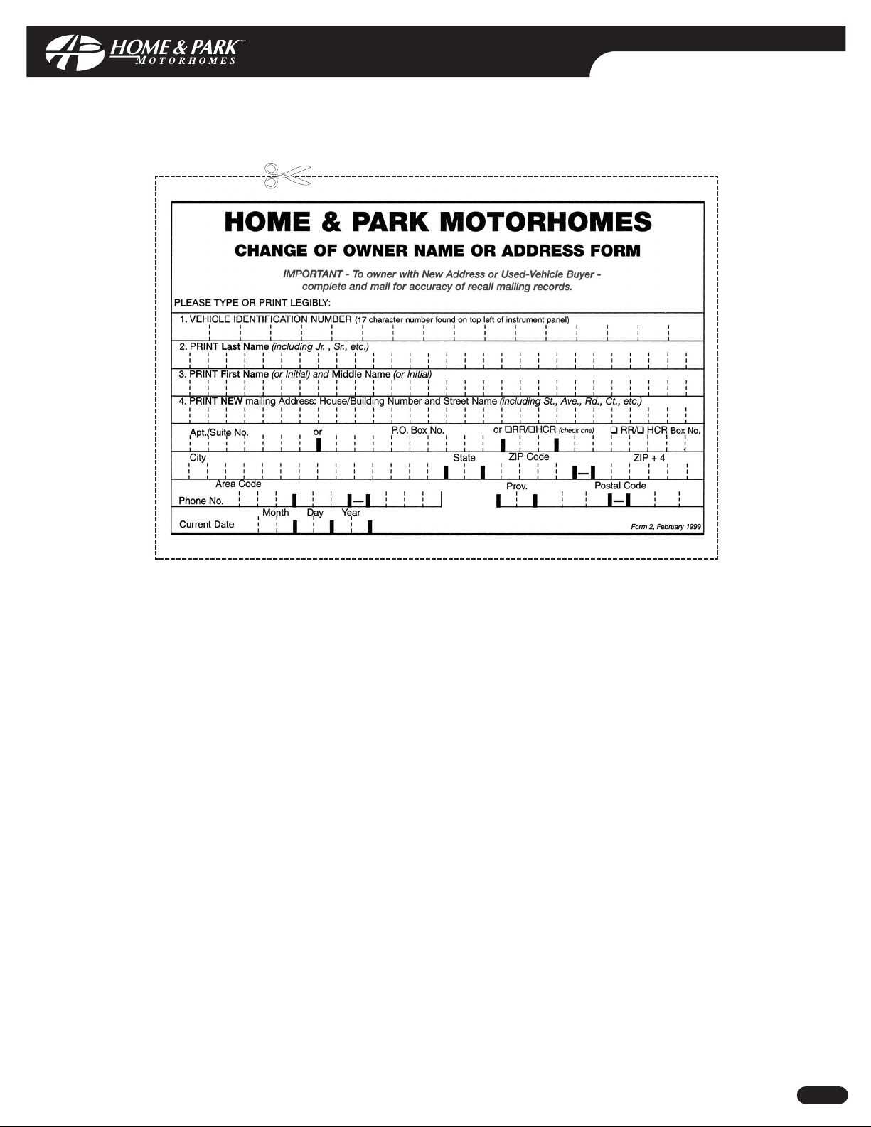
CHANGE OF ADDRESS FORM
DDoocc NNoo::
MNSA0006 Rev: 00
CCooppyyrriigghhtt©© HHaannmmaarr MMoottoorr CCoorrppoorraattiioonn 22000033 LL--22
Page 42
CHANGE OF ADDRESS FORM
DDoocc NNoo::
MNSA0006 Rev: 00
CCooppyyrriigghhtt©© HHaannmmaarr MMoottoorr CCoorrppoorraattiioonn 22000033 LL--33
Page 43
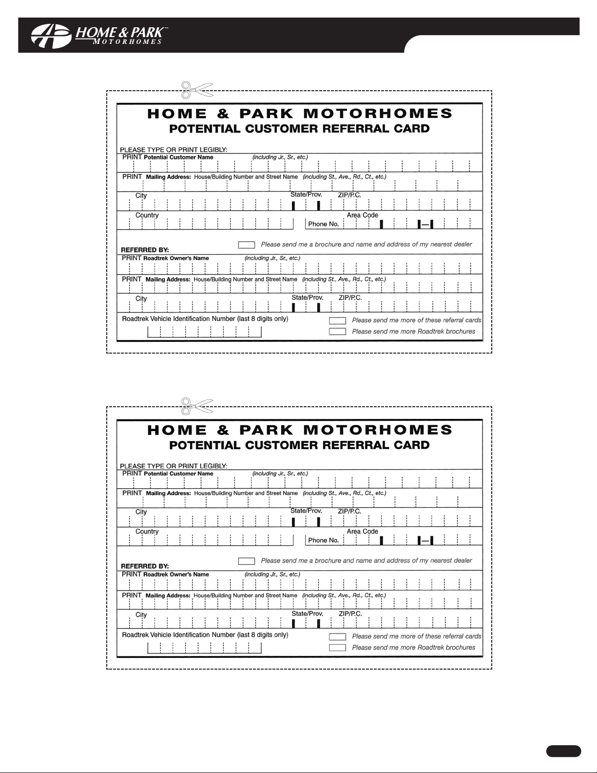
CUSTOMER REFERRAL CARD
DDoocc NNoo::
MNSA0006 Rev: 00
CCooppyyrriigghhtt©© HHaannmmaarr MMoottoorr CCoorrppoorraattiioonn 22000033 LL--44
Page 44
CUSTOMER REFERRAL CARD
DDoocc NNoo::
MNSA0006 Rev: 00
CCooppyyrriigghhtt©© HHaannmmaarr MMoottoorr CCoorrppoorraattiioonn 22000033 LL--55
Please contact Home & Park Motorhomes should you require additional customer referrral cards.
Page 45

Doc No: MNSA0006 Issue Date: March 2003 Copyright© Hanmar Motor Corporation 2003 Printed In Canada
TM
® "Home & Park" and "Roadtrek" are registered trademarks of J.J. Hanemaayer of which Hanmar Motor Corporation is a licensee and/or registered user
Division of HANMAR MOTOR CORPORATION
100 Shirley Avenue,Kitchener,Ontario,
Canada, N2B 2E1
Tel eph on e: 519-745-1169
or Toll Free 1-888-ROADTREK (1-888-762-3873)
Telefacsimile: 519-745-1160
Email: [email protected]
WebSi te: http://www.roadtrek.com/LIT
Doc No: MNSA0006 Issue Date: March 2003 Copyright© Hanmar Motor Corporation 2003 Printed In Canada
TM
® "Home & Park" and "Roadtrek" are registered trademarks of J.J. Hanemaayer of which Hanmar Motor Corporation is a licensee and/or registered user
Division of HANMAR MOTOR CORPORATION
100 Shirley Avenue,Kitchener,Ontario,
Canada, N2B 2E1
Tel eph on e: 519-745-1169
or Toll Free 1-888-ROADTREK (1-888-762-3873)
Telefacsimile: 519-745-1160
Email: service@roadtrek.com
WebSi te: http://www.roadtrek.com/LIT
 Loading...